

Page 1

99 Washington Street
Melrose, MA 02176
Phone 781-665-1400
Toll Free 1-800-517-8431
Visit us at www.TestEquipmentDepot.com
Instruction Manual
SM-8213
SM-8215
SM-8220
SUPER MEGOHMMETER
March 2013 Revised edition 5 SM8213A981-05 13-03H
Page 2

Page 3

The super megohmmeter is a unique resistance meter designed to measure highresistance in a wide range.
The meter outputs a high test voltage – 1000 V maximum for the SM-8220/8215, and 100 V
maximum for the SM-8213 – to apply across the sample circuit.
Operators are requested to read this operation manual thoroughly before trying to operate the
instrument for safety and to prevent electrical shock and damage to the measured circuit.
Keep this manual where all staff can access it any time.
i
Page 4
1. Safety Precautions
Operators of the SM-8200 Series super megohmmeter are requested to read this operation
manual thoroughly before operation for safety and to obtain best performance.
Operators are also requested to strictly observe all the DANGER, WARNING, and CAUTION
notices in this manual and on the instrument to prevent injury and damage.
1-1 Safety Warnings
This operation manual includes some DANGER!, WARNING!, and CAUTION! notice with a
symbol. These must be observed for safety of the operator and other persons, as well as for
protection of your super megohmmeter and samples from possible damage and destruction.
A “DANGER” CALLS ATTENTION TO A CONDITION OR POSSIBLE
SITUATION THAT CAN CAUSE DEATH OR INJURY TO THE
OPERATOR OR NEAR PESONS.
A “WARNING” CALLS ATTENTION TO A CONDITION OR POSSIBLE
SITUATION THAT COULD CAUSE DEATH OR INJURY TO THE
OPERATOR OR NEAR PESONS.
could cause injury to the operator or persons nearby and damage and
destroy the super megohmmeter and samples.
DANGER
WARNIN G
CAUTION
A “CAUTION” calls attention to a condition or possible situation that
ii
Page 5

This symbol is s how n a t p ats w h ose us age needs
This symbol is shown at the Rx
Measuring term inals which carry a high voltage
This symbol is shown at the GND
cannot be grounded, this terminal must be
connected to the ground.
2) DANGER and WARNING Labels on the Rear Panel
1.2 Symbols on the Super Megohmmeter
Symbol Meaning Description
WARNING
DANGER –
referen ce to t he op erati on ma nual.
HIGH VOLTAGE
HAZARD
to be applied across the circuit to be measured.
terminal on the rear of the unit. If the
ground prong of the power cord plug
Safety Warning Labels on the Super Megohmmeter
警告、危険シール
1) DANGER and WARNING Labels on the Housing and Front Panel
““/”+”
正面パネル
背面パネル
危険
DANGER
高電圧危険
端子より高電圧発生の為、
感電の恐れあり。
HIGHVOLTAGE
Terminals carry high voltage.
Elec tric shock hazard!
iii
Page 6
2. Op
s
t
8220/8215) or 100 V
(SM-8213) for measurement.
d
on the r ear of the in stru men t to a
ground. When the power cord plug is connected to the AC line socket via an
prong adapter, the green ground tab of the ad apter to the
t
may be present for several minutes after the
contact
s
n
Use the right size and amperage power fuse. If a fuse of incorrect amperage is inserted
is not level or
erating Environmental Precautions
D
DANGER
■Do not operate the super megohmmeters in the presence of flammable gas. There is
possibility of an explosion and/or fire.
■Do not touch the Rx “–”/“+” measuring terminals on the front panel of the instrumen
during measurement. They output a maximum of 1000 V (SM-
WARNING
■ Ground the ground prong of the power cord plug to avoid electrical shock. If the groun
prong cannot be grounded, connect the GND terminal
accessory 3-prong to 2ground.
■ Do not remove the housing cover of the instrument. Even after turning off the instrumen
powe
r switch, a dangerous residual voltage
power is turned off. If repair or internal readjustment is needed, contact your
your dealer or Hioki representative.
CAUTION
■Before turning on the power switch for the instrument, check that the VOLTAGE
SELECTOR switches are set for your local AC line voltage. If the wrong AC line voltage i
applied to the unit, it will be damaged (higher voltage supply) or will not functio
properly (lower voltage supply).
See 1.3 Setting VOLTAGE SELECTOR Switches for setting.
into the fuse holder, the unit will be damaged.
See 1.4 Checking the Fuse Amperage for a correct fuse amperage.
Do not insta ll or operate the supe r meg hommeter on a su rface w hich
■
not stable.
iv
Page 7
3. Inst
Do not install or place the super megohmmeter in a location which is not level, not
h
absorbing
r
f
5 to
allation Precaution
CAUTION
stable or not sturdy enough to hold the instrument and other related items.
4. Instrument Handling Precautions
WARNING
■ If the instrument generates smoke or smell, unplug the power cord.
If such an instrument is kept powered on, it may cause a fire.
contact y our d ealer or Hi oki rep res entati ve fo r repa ir.
■Do not o pera te th e ins trum ent wi th a w et han d. Thi s ma y caus e elec tri cal sho ck.
CAUTION
■When moving or transporting the super megohmmeter, avoid shock and vibration as muc
as possible. For long-distance transportation, put the instrume nt in a shock-
carton or use the original shipping carton.
■When not using the super megohmmeter for an extended period of time, unplug the powe
from the AC line socket. Put a dust cover on the instrument. Store it in a place free o
cord
corrosive gas and vibration, with a surrounding temperature within the range from –
45℃, and humidity 80% RH or less(non-condensating).
■Do not pl ace an ythi ng on th e inst rum ent.
v
Page 8

BRIEF DESCRIPTION
About the SM-8200 Series Super Megohmmeters
The SM-8200 Series super megohmmeters are insulation resistance meters consisting of a constant voltage
power supply and a high sensitive current measuring section. The super megohmmeters are designed to
measur e the el ect rical resi stan ce of i nsul atin g mat erial s with high insul atio n pro perti es.
The resistance measuring ranges of the SM-8200 S eries are as follows:
SM-8213: 2.5×10⁴ to 2×10¹²Ω
SM-8215: 2.5×10⁵ to 2×10¹³Ω
SM-8220: 5.0×10⁴ to 2×10
16
Ω
Each model of the super megohmmeters is provided with an LCD 320×240 dot display for easy
observation of necessary information, including measuring voltage, measured resistance in both
digital and analog, timer, and resultant GO/NO judgment.
The following shows the main specifications for the super megohmmeters.
For detailed specifications, see 2. SPECIFICATIONS.
For optional accessories, see 9. OPTIONAL ACCESSORIES.
Main Specific ations –
For optional accessories, see 9. OPTIONAL ACCESSORIES.
For detailed spec ifications , see 2. SPEC IFICATIONS.
Measuring Voltage Ranges:
SM-8213 – 5, 10, 15, 25, 50 and 100 V
SM-8215 – 50, 100, 250, 500 and 10 00 V
SM-8220 – 10, 25, 50, 100, 250, 500 an d 1000 V
Measuring Resistance Range:
SM-8213: 2.5×10⁴ to 2×10¹²Ω
SM-8215: 2.5×10⁵ to 2×10¹³Ω
SM-8220: 5.0×10⁴ to 2×10
16
Ω
Timer Function: Provided
Comparison and Judgme nt Function: Pro vided
HV-EN (High Voltage Enable) Interlocking Function: Provided
Voltage Charging Function: Provided
Voltage Discharging Function: Provided
RS-232C Interface Conn ector: Provided
Remote Measurement Function: Provided
vi
Page 9

Organization of This Operation Manual
This operation manual contains the following 10 sections.
1. PREPARATION BEFORE
This section describes precautions for unpacking and AC line voltage setting.
2. SPECIFICATIONS
This section describes the specifications for the SM-8200 Series super megohmmeters and
optional accessories.
3. OPERATING PRINCIPLE
This section describes the operating pri nciple with a block diagram of the SM-8200 Series.
4. FAMILIARIZATION WITH CONTROLS AND PARTS
This section describes the functions of the controls and parts on the front and rear panels.
5. PREPARATION FOR MEASUREMENT
This section describes the LCD display in detail for the measuring mode, setting mode and
operations. A variety of measured value display methods are also given.
OPERATION
6. MEASUREMENT
This section provides details for function setting, connection to the work to be measured, and
usage of a vari ety of opti onal measur ing jigs a nd el ectro des.
7. RS-232C INTERFACE
This section describes the application of the serial port interface.
8. REMOTELY CONTROLLED MEASUREMENT
This section describes the remote measuring function.
9. INTRODUCTION OF O PTIONALS
This section describes the optional accessories, including guard chips, DC signal outputs, and
others.
10. MAINTENANCE AND MISCELANEOUS
This section describes maintenance and calibration.
EXTERNAL APPEARANCE
11.
This sec tio n incl ude s fro nt, r ear an d sid e view illu strat ion s of th e inst rum ent w ith di men sion s.
vii
Page 10

Page 11

CONTENTS
1. PRE PA RAT IO N BE FO RE O PER AT ION . . . . . . . . . . . . . . . . . . . . . . . 1
1. 1 Unpacking and Checking of the Contents . . . . . . . . . . . . . . . . . . . 1
1. 2 Operating AC Line V oltage . . . . . . . . . . . . . . . . . . . . . . . . . . . . . . 2
1. 3 Setting the VOLTAGE SELECTOR Switches . . . . . . . . . . . . . . . . . . 2
1. 4 Checking the Fuse Amperage. . . . . . . . . . . . . . . . . . . . . . . . . . . . . 3
1. 5 Grounding the Chas sis . . . . . . . . . . . . . . . . . . . . . . . . . . . . . . . . . . 4
1. 6 Wa rm-up Period . . . . . . . . . . . . . . . . . . . . . . . . . . . . . . . . . . . . . . . 5
2. SPECIFICATIONS . . . . . . . . . . . . . . . . . . . . . . . . . . . . . . . . . . . 6
2.1 Measuring Performance . . . . . . . . . . . . . . . . . . . . . . . . . . . . . 6
2.2 Function Specifications . . . . . . . . . . . . . . . . . . . . . . . . . . . . 7
2.3 Other Electrical and Physical Data . . . . . . . . . . . . . . . . . . . . 8
2.4 Optional Functions and Accessories . . . . . . . . . . . . . . . . . . . 8
2.5 List of Measurement Ranges and Guaranteed Accuracy
Ranges by Model. . . . . . . . . . . . . . . . . . . . . . . . . . . . . . . . . . . 9
3. OPERATING PRINCIPLE . . . . . . . . . . . . . . . . . . . . . . . . . . . . . . . 12
4. FAM IL IAR IZA TIO N W ITH CON TR OLS AN D PA RTS . . . . . . . . . . . . . 13
4.1 Front Panel . . . . . . . . . . . . . . . . . . . . . . . . . . . . . . . . . . . . 13
4.2 Rear Panel . . . . . . . . . . . . . . . . . . . . . . . . . . . . . . . . . . . . . 15
4.3 Measuring Display . . . . . . . . . . . . . . . . . . . . . . . . . . . . . . . 17
4.4 Measuring Condition Setting Display . . . . . . . . . . . . . . . . . . 18
4.5 Meanings of the Status and Mode Notices. . . . . . . . . . . . . . . . 19
5. PREPARATION FOR A MEASUREMENT . . . . . . . . . . . . . . . . . . . . . 20
5.1 Preparation. . . . . . . . . . . . . . . . . . . . . . . . . . . . . . . . . . . . . 20
5.2 Self-calibration 1. . . . . . . . . . . . . . . . . . . . . . . . . . . . . . . . . 21
5.3 Self-calibration 2. . . . . . . . . . . . . . . . . . . . . . . . . . . . . . . . . 21
5.4 Check the Measuri ng Rods
. . . . . . . . . . . . . . . . . . . . . . . . . . 22
5.5 Basic Procedures for a Measurement. . . . . . . . . . . . . . . . . . . 23
6. MEASUREMENT. . . . . . . . . . . . . . . . . . . . . . . . . . . . . . . . . . . . 24
6.1 Measuring Method. . . . . . . . . . . . . . . . . . . . . . . . . . . . . . . . 24
6.2 Discharging Function . . . . . . . . . . . . . . . . . . . . . . . . . . . . . 25
6.3 Charging Function . . . . . . . . . . . . . . . . . . . . . . . . . . . . . . 25
6. 4 In ter loc kin g F unc ti on – Usi ng the HV -EN Con ne cto r . . . . . . . . 26
6.5 Comparison and Judgment Function . . . . . . . . . . . . . . . . . . . 27
a
Page 12

6.6 Setting a Variety of Functions . . . . . . . . . . . . . . . . . . . . . . . 28
6.6.1 Setting the Timer . . . . . . . . . . . . . . . . . . . . . . . . . . . . . . . 28
6.6.2 Setting the Comparison GO/NO Judgment Level . . . . . . . . . 28
6.6.3 Setting Buzzer Sound ON/OFF . . . . . . . . . . . . . . . . . . . . . . 29
6.6.4 Setting the Charging Time, Measu ring Time, Comparison
GO/NO Judging Level and Buzzer Sound ON/OFF. . . . . . . . . 29
6.7 Changes in the Current Flowin g through Insulators. . . . . . . . . 31
6.8 Connectivity Precautions. . . . . . . . . . . . . . . . . . . . . . . 32
6.8.1 When the Screen Shows LOCK and Measurement Cannot Be Started . . .32
6.8.2 When Using an Optional Electrode for Plate Samples or Shield Box . .33
7. RS-232C INTERFACE . . . . . . . . . . . . . . . . . . . . . . . . . . . . . . . . 34
7.1 RS-232C Communication Commands . . . . . . . . . . . . . . . . . . . 34
7.2 Applications of Commands . . . . . . . . . . . . . . . . . . . . . . . . . . 35
7.3 Connector Specifications. . . . . . . . . . . . . . . . . . . . . . . . . . . 35
7.4 Printer Output . . . . . . . . . . . . . . . . . . . . . . . . . . . . . . . . . . 36
8. REMOTELY CONTROLLED MEASUREMENT . . . . . . . . . . . . . . . . . 37
9. INTRODUCTION OF OPTI ONS . . . . . . . . . . . . . . . . . . . . . . . . . . . 40
9.1 DC Signal Outputs. . . . . . . . . . . . . . . . . . . . . . . . . . . . . . . . 40
9.1.1 DC Output, RP-8000
– Directly proportional or linear to resistance . . . . . . . . . . 40
9.1.2 DC Output, RI-8000
– Inversely proportional or 1/R to resistance . . . . . . . . . . 42
10. MAINTENANCE AND MISCELANEOUS . . . . . . . . . . . . . . . . . . . . 45
10.1 Periodical Checking . . . . . . . . . . . . . . . . . . . . . . . . . . . . . 45
10.2 Storage, Transportation and Abando n . . . . . . . . . . . . . . . . . 45
11. EXTERNAL APPEARANCE . . . . . . . . . . . . . . . . . . . . . . . . . . . . . 46
b
Page 13
1. PREPARATION BEFORE OPERATION
When plugging the shorting plug, make sure that the power is turned off, otherwise,
1.1 Unpacking and Chec king of the Conten ts
When you have received the carton of the SM-8200 Series super megohmm eter, carefully unpack
it, and take out every thing from the carton.
Although the instrument and its accessories are severely inspected before shipment from factory,
visual ly ch eck t he it ems a nd th eir q uanti ties .
Keep t he shi ppi ng ca rton for r euse a t a lat er st age.
1) Visually check the external view of the instrument and its accessories.
2) Check the qu anti ties o f the l ist in acco rdan ce wit h the f ollow ing l ist:
Table 1.1 List of Standard Accessories
Item Model No. Q’ty Remarks
Operation manual
Power cord
Measuring rod
(Red)
Measuring rod
(Black)
Shorting plug 0GZ00003 1
-
-
0GE00002 1
0GE00001 1
This item means this booklet.
1
Power cord with 3-prong plug with third
1
for grounding
A measuring rod with a 1meter cord to be connected to the Rx ‘’
socket.
A measuring rod with a 1meter cord to be connected to the Rx ‘+’
socket.
A plug to be plugged to the
HV-EN so cket of th e rear of
the inst rumen t. It i s plu gged
to the HV-EN socket when
shipping from factory.
Important!
When the accessory shorting plug is not plugged to the HV-EN socket on the rear of the
instrument, the measuring high voltage is not output.
Note: The shorting plug is plugged to the HV-EN socket when shipping from factory.
CAUTION
there i s an el ectr ic sh ock h azar d.
Upon checking the instrument and accessories, if any damage is found, immediately contact
your dealer or Hioki representative.
1
Page 14
1.2 Operating AC Line Voltage
confirm that the VOLTAGE
SELECTOR switches on the rear panel are set to the positions, accordingly (See 1.3
The sup er megohmemet er c a n b e o p e ra ted fro m o ne of the f o llowin g A C power so u r c e w hen the
VOLTAGE SELECTOR switches are set accordingly.
AC Line Voltage
100 V ±10% 50/60 Hz
120 V ±10% 50/60 Hz
220 V ±10% 50/60 Hz
240 V +10V, 10% 50/60 Hz
CAUTION
1.3 Setting VOLTAGE SELECTOR Switches
The super megohmmeter can be operated from one of the AC line voltages of 100 V, 120 V, 220 V
Before connecting the power cord to the AC outlet socket,
Setting the VOLTAGE SELECTOR Switches.).
If the switches are set to wrong positions, a fire or burn may occur.
and 240 V by setting the VOLTAGE S ELECTOR switch es to the specific positio ns, respectively.
Frequency
Confirm the switch setting to the specific positions in accordance with Fig. 1.1.
If they are not set properly, correct their positions, accordingly.
To change the position of the switch, insert the tip of a flat blade screwdriver into the slot of the
switch lever, and slide the lever upward or downward.
CAUTION
To chan ge the V OLTA SGE SELE CTOR swit ch posi tio ns, be s ure t o
Unplug the po wer co rd pl ug fr om the A C li ne soc ket to preven t a
possible damage.
When th e swit ch po siti on is chan ged whi le t he vol tag e is on, the
Switch contacts will be damaged.
2
Page 15

up and down. Slide the
Do not leave the lever at a neutral position. If the lever is set at a neutral position, a
When the VOLTAGE SELECTOR switch position is changed, fuse amperage must be
Time Lag Fuse
CAUTION
The VOLTAGE SELECTOR switches have two positions –
switch lever to either position until it stops.
normal function cannot be obtained, and it will cause a failure.
G
A
T
L
O
V
100V
120V
220V
240V
E
R
O
T
C
E
L
E
S
Fig. 1.1 VOLTAGE SELECTOR Switch Setting
CAUTION
changed to m eet th e requ irem ents of th e new AC lin e volt age.
Incorr ect fu se am pera ge wi ll ca use a f ailu re of t he in strum ent .
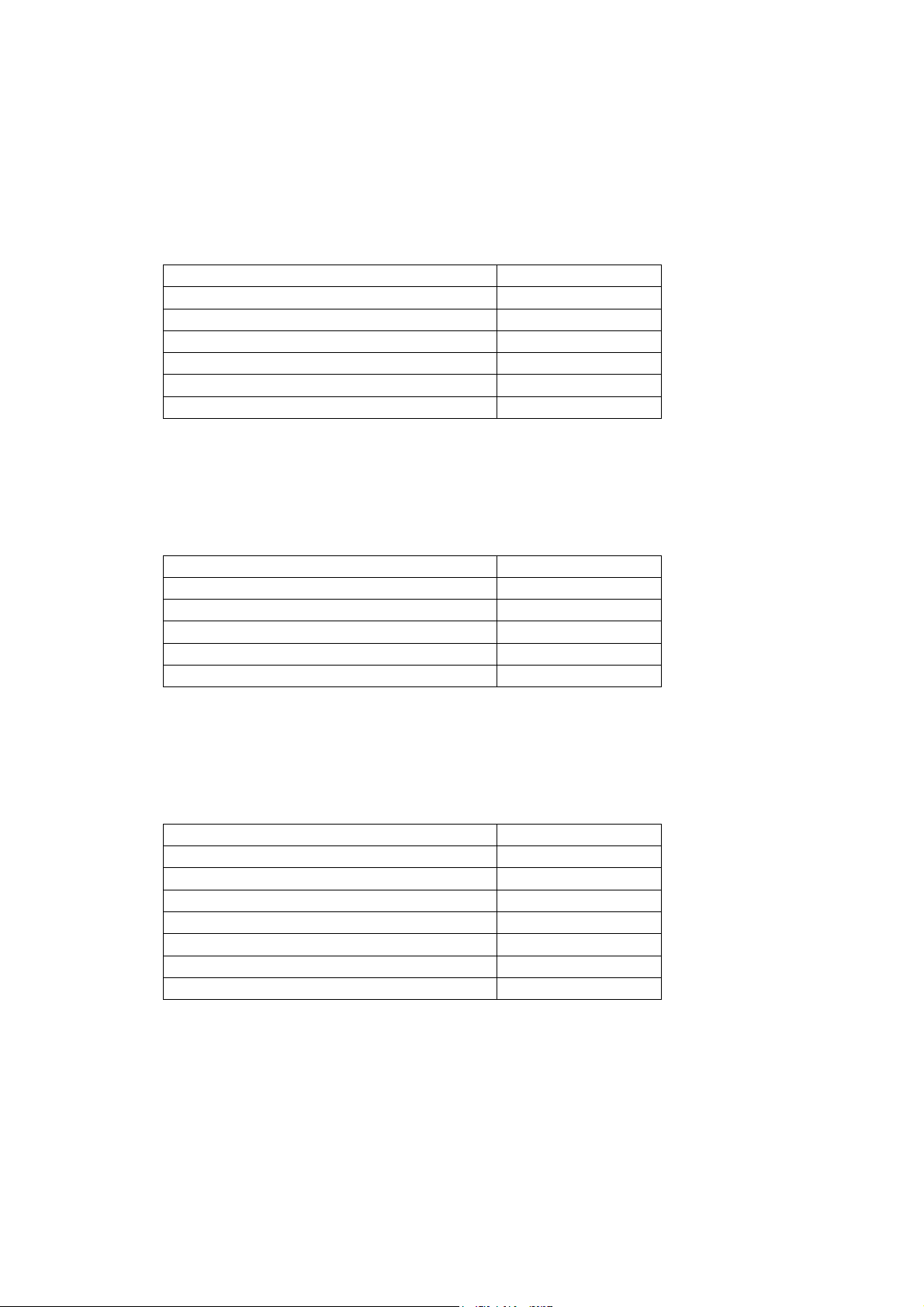
1.4 Checking the Fuse Amperage
The fuse holder of the instrument contains a time lag fuse of the following amperage:
AC Line Voltage
100 V/120 V 0.4 A
220 V/240 V 0.2 A
Fuse Amperage
3
Page 16
To replace or check the fuse, make sure to disconnect the power cord from the AC line
To prevent an accident, connect the ground prong of the power cord
sure to connect
p
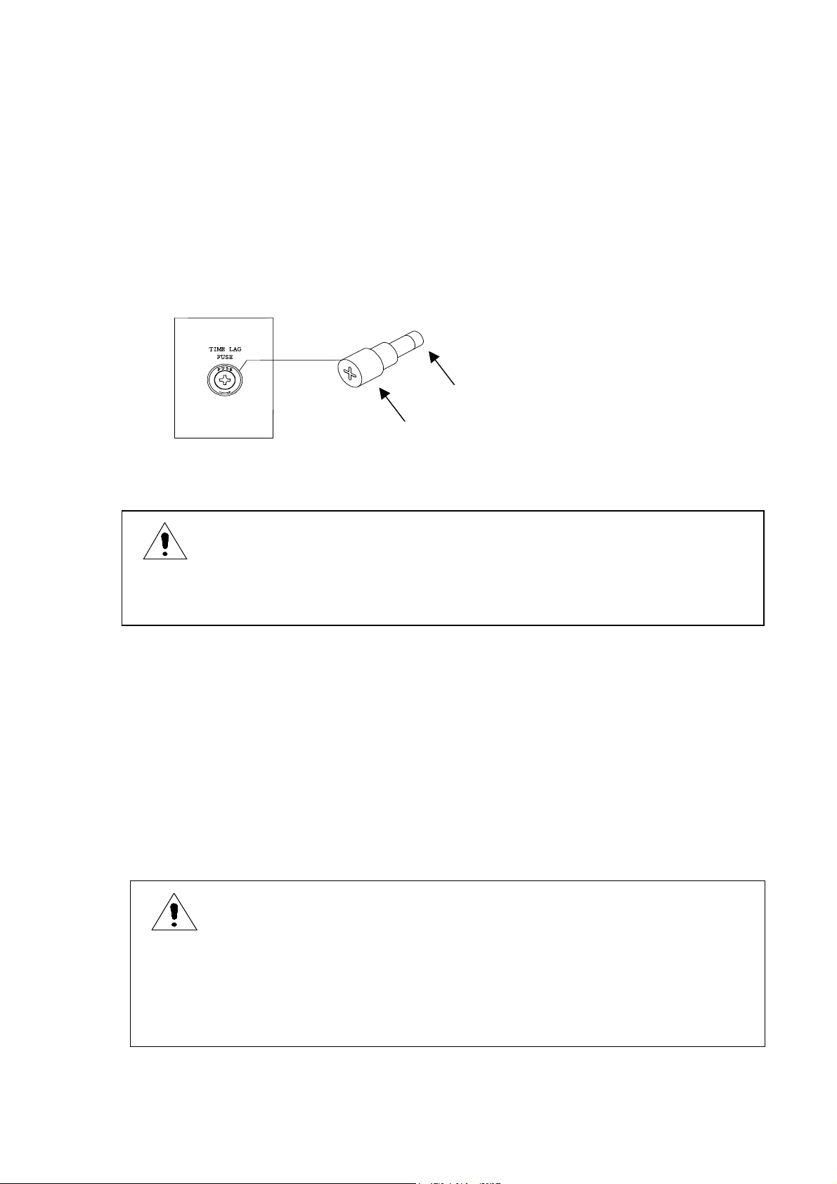
Fuse Replacement
The fuse is inserted in the FUSE holder (Fig. 1.2) on the rear of the unit.
Remove the cap, and replace the fuse with a new one with a correct amperage.
To remove the cap of the fuse holder, use a 4 mm Phillips screwdriver, and turn the cap
counterclockwise.
To set the cap in position, insert the cap, holding the fuse into the holder, and turn it with the
screwdriver.
Fuse
Fig. 1.2 Fuse Holder and Fuse Replacement
WARNING
socket. If not , ther e is a f ear of el ect rical shoc k.
Ca
1.5 Grounding the Chassis
To avoid an electr ical shock accid ent, connect the GND terminal on the rear of the unit to the
ground prong of the power cord to the ground post of the AC line system.
The round prong of the 3-prong plug o f the power cord is the grou nd prong.
It is recommended to use an AC line socket with its third contact grounded for connection of the
accessory 3-prong power cord.
To use the accessory 3-prong to 2-prong adapt er to connect the power cord to a 2-cont act AC line
socket, make sure to ground the green tab of the adapter.
WARNING
Plug to the ground post of the AC line system. If it is impossible to
ground the ground prong of the power cord plug, be
the GND terminal on the rear of the unit.
4
Page 17

1.6 Warm-up Period
To obtain the performance of published specifications, allow the SM-8200 Series super
megohmmeter to warm for a minimum of 30 minutes.
5
Page 18
2. SPECIFICATIONS
2.1 Measuring Performance
1) Electrical Resistance Measurement
SM-8213(RANGE : ×1 , ×10 , ×10
Measur em ent Ra nge (MΩ) [RANGE=×10
0.5 × 10R to 20 × 10R
0.25 × 10R to 10 × 10R
0.125 × 10R to 5 × 10R
0.075 × 10R to 3 × 10R
0.05 × 10R to 2 × 10R
0.025 × 10R to 1 × 10R
Accuracy of target voltage: ±3% of set value
Measuring output current: 50 mA maximum (Note: 1)
Accuracy of measurement: ±10% (A range of 10 times of the minimum
value of each range) (Note: 2)
SM-8215(RANGE : ×1 , ×10 , ×10
Measur em ent Ra nge (MΩ) [RANGE=×10
5 × 10R to 200 × 10R
2.5 × 10R to 100 × 10R
1.25 × 10R to 50 × 10R
0.5 × 10R to 20 × 10R
0.25 × 10R to 10 × 10R
Accuracy of target voltage: ±3% of set value
2
, ×103 , ×104 , or ×105)
R
]
Target Voltage
100 V
50 V
25 V
15 V
10 V
5 V
2
, ×103 , ×104 , or ×105)
R
]
Target Voltage
1000 V
500 V
250 V
100 V
50 V
Measuring output current: 2 mA maximum (Note: 1)
Accuracy of measurement: ±10% (A range of 10 times of the minimum
value of each range) (Note: 2)
2
SM-8220(RANGE : ×1 , ×10 , ×10
Measur em ent Ra nge (MΩ) [RANGE=×10
5 × 10R to 200 × 10R
2.5 × 10R to 100 × 10R
1.25 × 10R to 50 × 10R
0.5 × 10R to 20 × 10R
0.25 × 10R to 10 × 10R
0.125 × 10R to 5 × 10R
0.05 × 10R to 2 × 10R
, ×103 , ×104 , ×105 , ×106 , ×107 , or ×108)
R
]
Target Voltage
1000 V
500 V
250 V
100 V
50 V
25 V
10 V
Accuracy of target voltage: ±3% of set value
Measuring output current: 2 mA maximum (Note: 1)
Accuracy of measurement: ±10% (A range of 10 times of the minimum
8
value of each range) except for×10
±20% for×10
8
range
range. (N ote: 2)
6
Page 19

Note 1: The measurement output current may reach as high as approximately 1.4 times th e
maximum value. When a current in excess of the measurement output current’s
maximu m val ue is output , the s et m easur ement volt age m ay dro p.
Note 2: The measurement accuracy is defined as ±10% of the indicated measured value
displayed on the screen.
2) Measuring Time (Sampling Cycle)
Approx. 200 ms
2.2 Function Specifications
1) CHARGE Function
This function charges the sample to be measured by applying the Selected measuring
voltage when the CHARGE switch is pushed.
Internal Resistance
SM-8213: Approx. 0Ω
SM-8215: Approx. 30kΩ
SM-8220: Approx. 30kΩ
2) DISCHARGE Function
This function discharges a residual voltage on the sample after measurement when the
DISCHARGE switch is pushed.
Internal Resistance
All models: Approx. 100kΩ
3) HV-EN (High Voltage Enable) – Interlocking Function
This function externally controls to make the o utput of mea suri ng vo ltag e on or off.
This function is used in combination with an interlock switch on the measuring jig so as to
preven t an el ectr ical shoc k dur ing m easur em ent.
4) TIMER Function
This function determines the voltage charging time and the measuring time, respectively,
within a range from 1 to 999 s econds. Aft er the set ti me is up, the measur ed value is sho wn
held.
5) COMPARISON and JUDGMENT F unction
This function makes a comparison of the measured value with the preset judgment value,
and if the measured value is less than the judgment level, it makes the alert buzzer sound,
closing the incorporated relay contacts.
6) RS-232C Interface Functi on
This function allows a control of an optional print er via RS-232C interfac e.
The optional printer prints measured da ta.
7) REMOTE MEASUREMENT Function
This function allows a remotely controlled measurement by means of a remote switch.
7
Page 20

2.3 Other Electrical and Physical Data
1) Envi ronm ent al te mpera tur e and Hum idit y
Operation: 0 to 40℃ (SM-8213/8215),80% RH or l ess (non-condensat ing)
Storage: 5 to 45℃,80% RH or l ess(non-condensating)
5 to 35℃ (SM-8220),80% RH or less (non-condensating)
2) Power Requirements
AC 100 V, 120 V, 220 V, ±10%, 240 V +10 V, 10% 50/60 Hz
3) Power Consumption
Approx. 25 VA
4) Dimensions
Approx. 284 (W) × 139 (H) × 215 (D) mm
Also, see 11. EXTERNAL VIEW for external appearance.
5) Weight
Approx. 4.3 kg
2.4 Optional Functions and Accessories
In addition to the standard accessories shown in 1.1 Unpacki ng and Chec king of th e Content s
and Table 1.1 List of Standard Accessories, the following two groups of optiona l acce ssories are
available to expand the applic ations of the SM-820 0 Series super megohmm eters.
1) Options – designed exclusive for the SM-8200 Series
Name Model
Printer 9442
2) Options – designed for common to SM- 8200 Series, SM-8216, and
SM-8000 Series super megohmmeters.
Name Model Description
With surface/volumetric
selector, interlock function
Selector. Needs shield box.
resistance measurement
resistance measurement
Electrode constant: Appro x. 500 cm
measurement of antistatic flooring,
etc.
Electrode for plate sampl es SME-8310
Electrode for plate sampl es SME-8311
Weight electrode SME-8320 With surface/volumetric
Shield box SME-8350 Electromagnetic shieldin g
Electro de fo r surf ace
resistance measurement
Electro de fo r surf ace
resistance measurement
Electrodes for liquid sample
measur em ent
Surface/Volume
Resistance Measurement
Electr od e
Electro des fo r chi p
capacitors
SME-8301 Simplified electrode for surfa ce
SME-8302 Simplified electrode for curved surface
SME-8330 Capacity, approx. 25 mL
SM9001 Surface/volume resistance
SME-8360 Chip capacitor measurement
8
Page 21

2.5 List of Measurement Ranges and Guaranteed Accuracy Ranges by Model
SM-8213
Voltage
5V
10V
15V
25V
50V
100V
*All resistance values are expressed in MΩ.
Range/measurement range (with guaranteed accuracy range in parentheses)[MΩ]
×1 ×10 ×10
:
:
:
:
:
:
1
1
)
1
1
)
1
1
)
1
1
)
1
1
)
1
1
)
0.025×100
:
1.00×100
(0.250×10
0.050×100
:
2.00×100
(0.500×10
0.075×100
:
3.00×100
(0.750×10
0.125×100
:
5.00×100
(1.25×10
0.250×100
:
10.0×100
(2.50×10
0.500×100
:
20.0×100
(5.00×10
0.025×10
1.00×101
0
)
(0.250×10
0.050×10
2.00×101
0
)
(0.500×10
0.075×10
3.00×101
0
)
(0.750×10
0.125×10
5.00×101
0
)
(1.25×10
0.250×10
10.0×101
0
)
(2.50×10
0.500×10
20.0×101
0
)
(5.00×10
(0.250×10
(0.500×10
(0.750×10
2
0.025×10
:
1.00×10²
0.050×10
:
2.00×10²
0.075×10
:
3.00×10²
0.125×10
:
5.00×10²
(1.25×10
0.250×10
:
10.0×10²
(2.50×10
0.500×10
:
20.0×10²
(5.00×10
×103 ×104 ×105
2
0.025×10
1.00×10³
2
)
(0.250×10
0.050×10
2
2.00×10³
2
)
(0.500×10
0.075×10
2
3.00×10³
2
)
(0.750×10
0.125×10
2
5.00×10³
2
)
2
(1.25×10
0.250×10
10.0×10³
2
)
2
(2.50×10
0.500×10
20.0×10³
2
)
(5.00×10
:
:
:
:
:
:
3
0.025×10
:
1.00×10⁴
3
)
(0.250×10
0.050×10
3
:
2.00×10⁴
3
)
(0.500×10
0.075×10
3
:
3.00×10⁴
3
)
(0.750×10
0.125×10
3
:
5.00×10⁴
3
)
3
(1.25×10
0.250×10
:
10.0×10⁴
3
)
3
(2.50×10
0.500×10
:
20.0×10⁴
3
)
(5.00×10
4
0.025×10
5
:
1.00×10⁵
4
)
(0.250×10
0.050×10
4
5
)
5
:
2.00×10⁵
4
)
(0.500×10
0.075×10
4
5
)
5
:
3.00×10⁵
4
)
(0.750×10
0.125×10
4
5
)
5
:
5.00×10⁵
4
)
4
(1.25×10
0.250×10
5
)
5
:
10.0×10⁵
4
)
4
(2.50×10
0.500×10
5
)
5
:
20.0×10⁵
4
)
(5.00×10
5
)
9
Page 22

SM-8215
Voltage
50V
100V
250V
500V
1000V
*All resistance values are expressed in MΩ.
Range/measurement range (with guaranteed accuracy range in parentheses) [MΩ]
×1 ×10 ×10
1
:
:
:
:
:
1
1
)
1
1
1
)
1
1
1
)
1
1
)
1
1
)
0.250×100
:
10.0×100
(2.50×10
0
0.500×10
:
20.0×10
(5.00×10
1.25×10
0
0
0
:
50.0×10
(12.5×10
0
0
2.50×100
:
100×100
(25.0×10
0
5.00×100
:
200×100
(50.0×10
0
0.250×10
10.0×10
)
0
)
)
(2.50×10
0.500×10
20.0×10
(5.00×10
1.25×10
50.0×10
(12.5×10
2.50×10
100×101
)
(25.0×10
5.00×10
200×101
)
(50.0×10
2
0.250×10
:
10.0×10
(2.50×10
0.500×10
:
20.0×10
(5.00×10
1.25×10
:
50.0×10
(12.5×10
2.50×10
:
100×102
(25.0×10
5.00×10
:
200×102
(50.0×10
×103 ×104 ×105
2
2
2
)
2
2
2
)
2
2
2
)
2
0.250×10
10.0×10
(2.50×10
0.500×10
20.0×10³
(5.00×10
1.25×10
50.0×10
(12.5×10
2.50×10
100×103
2
)
2
(25.0×10
5.00×10
200×103
2
)
(50.0×10
:
:
:
:
:
3
3
3
)
3
0.250×10
10.0×10⁴
(2.50×10
0.500×10
20.0×10
3
)
3
3
3
)
3
(5.00×10
1.25×10
50.0×10
(12.5×10
2.50×10
100×104
3
)
3
(25.0×10
5.00×10
200×104
3
)
(50.0×10
:
:
:
:
:
4
0.250×10
:
10.0×10
4
)
4
(2.50×10
0.500×10
:
4
4
)
4
20.0×10
(5.00×10
1.25×10
:
4
4
)
4
50.0×10
(12.5×10
2.50×10
:
100×105
4
)
4
(25.0×10
5.00×10
:
200×105
4
)
(50.0×10
5
5
5
)
5
5
5
)
5
5
5
)
5
5
)
5
5
)
10
Page 23

SM-8220
Voltage
10V
25V
50V
100V
250V
500V
1000V
*All resistance values are expressed in MΩ.
Range/measurement range (with guaranteed accuracy range in parentheses) Voltage [MΩ]
2
×1 ×10 ×10
0.050×10
:
2.00×10
(0.500×10
0.125×10
:
5.00×10
(1.25×10
0.250×10
:
10.0×100
(2.50×10
0.500×10
:
20.0×100
(5.00×10
1.25×10
:
50.0×100
(12.5×10
2.50×10
:
100×100
(25.0×10
5.00×10
:
200×100
(50.0×10
0
0
0
)
0
0
0
)
0
0
)
0
0
)
0
0
)
0
0
)
0
0
)
0.050×10
:
2.00×10
(0.500×10
0.125×10
:
5.00×10
(1.25×10
0.250×10
:
10.0×10
(2.50×10
0.500×10
:
20.0×10
(5.00×10
1.25×10
:
50.0×101
(12.5×10
2.50×10
:
100×101
(25.0×10
5.00×10
:
200×101
(50.0×10
1
1
1
)
1
1
1
)
1
1
1
)
1
1
1
)
1
1
)
1
1
)
1
1
)
0.050×10
:
2.00×10
(0.500×10
0.125×10
:
(1.25×10
0.250×10
:
(2.50×10
0.500×10
:
(5.00×10
1.25×10
:
(12.5×10
2.50×10
:
100×102
(25.0×10
5.00×10
:
200×102
(50.0×10
×103 ×104 ×105 ×106 ×107 ×108
2
2
2
)
2
2
5.00×10
2
)
2
10.0×10²
2
)
2
20.0×10²
2
)
2
50.0×10²
2
)
2
2
)
2
2
)
0.050×10
:
2.00×10
(0.500×10³)
0.125×10
:
5.00×10³
3
(1.25×10
0.250×10
:
10.0×10³
3
(2.50×10
0.500×10
:
20.0×10³
3
(5.00×10
3
1.25×10
:
50.0×10³
3
(12.5×10
3
2.50×10
:
100×103
3
(25.0×10
3
5.00×10
:
200×103
3
(50.0×10
3
3
3
)
3
)
3
)
)
)
)
0.050×10
:
2.00×10⁴
(0.500×10
0.125×10
:
5.00×10
(1.25×10
0.250×10
:
10.0×10⁴
(2.50×10
0.500×10
:
20.0×10⁴
(5.00×10
1.25×10
:
50.0×10⁴
(12.5×10
2.50×10
:
100×104
(25.0×10
5.00×10
:
200×104
(50.0×10
4
4
)
4
4
4
)
4
4
)
4
4
)
4
4
)
4
4
)
4
4
)
0.050×10
:
2.00×10
(0.500×10
0.125×10
:
5.00×10
(1.25×10
0.250×10
:
10.0×10⁵
(2.50×10
0.500×10
:
20.0×10⁵
(5.00×10
1.25×10
:
50.0×10⁵
(12.5×10
2.50×10
:
100×105
(25.0×10
5.00×10
:
200×105
(50.0×10
5
5
5
)
5
5
5
)
5
5
)
5
5
)
5
5
)
5
5
)
5
5
)
0.050×10
:
2.00×10⁶
(0.500×10
0.125×10
:
5.00×10
(1.25×10
0.250×10
:
10.0×10⁶
(2.50×10
0.500×10
:
20.0×10⁶
(5.00×10
1.25×10
:
50.0×10⁶
(12.5×10
2.50×10
:
100×106
(25.0×10
5.00×10
:
200×106
(50.0×10
6
6
)
6
6
6
)
6
6
)
6
6
)
6
6
)
6
6
)
6
6
)
0.050×10
:
2.00×10
(0.500×10
0.125×10
:
5.00×10⁷
(1.25×10
0.250×10
:
10.0×10⁷
(2.50×10
0.500×10
:
20.0×10⁷
(5.00×10
1.25×10
:
50.0×10⁷
(12.5×10
2.50×10
:
100×107
(25.0×10
5.00×10
:
200×107
(50.0×10
7
7
7
)
7
7
)
7
7
)
7
7
)
7
7
)
7
7
)
7
7
)
0.050×10
:
2.00×10⁸
(0.500×10
0.125×10
:
5.00×10
(1.25×10
0.250×10
:
10.0×10
(2.50×10
0.500×10
:
20.0×10⁸
(5.00×10
1.25×10
:
50.0×10⁸
(12.5×10
2.50×10
:
100×108
(25.0×10
5.00×10
:
200×108
(50.0×10
8
8
)
8
8
8
)
8
8
8
)
8
8
)
8
8
)
8
8
)
8
8
)
11
Page 24

3. OPEARATING PRINCIPLE
The SM-8200 Series super megohmmeters consist of a constant voltage power supply and a high
sensitive current measuring section to be combined to compose a resistance measuring circuit.
The current measuring section is composed of a current detective resistor, low drift voltage
amplifier and an integrator-type A/D converter.
A measured resistance value is computation-processed by a CPU to display the result on a liquid
crystal display (LCD).
Fig. 3.1 shows a circuit composition of the SM-8200 Series.
(Option)
DC
(-)
Rx
RANGESele ctor
Currentto Voltager
MEAS
CHARGE
DISCHARGE
e
g
r
a
h
c
s
i
D
t
i
u
c
r
i
C
Converte
DC
Amplifier
Discharge
Controller
Signal Output
Control Keys
A/D
Converte r
CPU
RS-232C
LCD
VOLTAGE SELECTOR
Switches
(+)
MEAS
CHARGE
DISCHARGE
-
High Volta ge
Power Supply
+
Fig. 3.1 Circuit Composition
AC Li ne Source
Power
Supply
12
Page 25

4. FAMILIARIZATION WITH CONTROLS AND PARTS
4.1 Front Panel
The figure below shows the front panel of the SM-8200 Series. However, note that the values for
the two knobs on the right are represent ed by those of the SM- 8213.
②
①
Fig. 4.1 Front Panel
③
④
⑥⑤
⑨⑧⑦
① LCD Display: This is a 320×240 dot liqu id crystal display modul e.
This shows measured results, measuring conditions and a variety of
data settings.
② POWER Switch: T his i s a po wer s witch to t urn o n or o ff th e ins trument s.
A press of this switch in the released position turns ON the unit.
A press of this switch in the pushed position turns OFF the unit.
⑪
⑩
③ V. OUT Indicator: This indicato r lights when the Rx /+ measuring
terminals carry a measuring voltage across them.
④
voltage across them to measure the insulation resistance of a sample
via a pair of measuring rods or electrodes.
Note: Each of the terminals is incorporated with a plug insertion
detector switch. Unless otherwise this switch is turned on by a
full insertion of the plug of the measuring rod or electrode, the
output voltage circuit cannot be completed – no output.
Pease be careful when inserting or removing the plug so as not
to cause any impact on the detection switch inside the terminal.
Rx /+ Measuring Terminals: These terminals carry a selected measuring
13
Page 26

⑤ SELECT Switch: This switch moves the curso r in th e LCD d ispl ay to the
desired item set it.
This switch also acts as a STOP switch; this switch makes the voltage
on the Rx /+
the measuring voltage is being applied.
⑥
pressed.
⑦
⑧
measuring terminals to charge the sample to be measured when it is
pressed. During the chargi ng period, th e V. OUT indicator light s.
the next press of this switch discharges the sample, turning off the
V. OUT indicator.
Note: When the timer function is used to determine the charging
period, the measurement automatically starts when the set
time is up.
⑨
sample in connection, when it is pressed, turning on the
incorporated indicator and the V. OUT indicator.
The next press of this switch discharges the sample, turning off the
DOWN Switch: This switch decreases the value to set each time it is
UP Switch: This switch increases the value to set each time it is pressed.
CHARGE Switch: This switch applies the measuring voltage across the Rx
MEASUR E/D ISCH ARGE Swit ch: Th is swit ch st arts a measu rem ent of the
measuring terminals OFF when it is pressed while
two indicators.
⑩
across the Rx +/
a voltage to output.
VOLTAGE Selector Switch: This switch selects the voltage to be applied
measuring terminals. The arrow on the knob shows
⑪ RANGE Selector Switch: This switch selects a factor for the measur ed
value.
The selected factor is also shown at the ×10 multiplier area.
14
Page 27

4.2 Rear Panel
The figure below shows the rear pan el of the SM-8200 Series. However, not e
that the VOLTAGE SELECTO R switches are set for the op eration from 100 V
AC line.
⑱⑰ ⑯ ⑮
Fig. 4.2 Rear Panel
⑭⑬⑫
⑫
accordance with the local AC line voltage (50 or 60 Hz) fo r the
instrument.
For a proper setting, see 1.3 Setting VOLTAGE SELECTOR Switches.
For line voltage change betw een 100 V/120 V and 220 V/24 0 V, the
power fuse amperage must be also changed accordingly.
⑬
⑭
tube. T he am perag e of t he fus e must agr ee wit h the l ocal AC lin e
voltage from which the unit is powered.
AC Line Voltage
100 V/120 V (50/60 Hz) 0.4 A
220 V/240 V (50/60 Hz) 0.2 A
Note: When the AC line voltage for the unit is changed after receipt of
your super megohmmeter, check the fuse amperage.
VOLTAG E SEL ECTO R Swi tch es: Th ese tw o swi tches are t o be s et in
AC LINE Receptacle: This connects the accessory power cord.
TIME LAG FUSE Holder: This holder contains a time lag fuse in a glass
Fuse Amperage
⑮ GND Terminal: This is a ground terminal connected to the chassis of the
unit.
15
Page 28

⑯
signals measured result judgment outputs, optional DC output, and
remote signal input.
For details, see the following sections;
6.5 Comparison and Judgment Function
8. MEMORY CONTROLLED MEASUREMENT
9.2 DC Signal Output
⑰
provided for connection of an external interlocking switch on the
measuring jig designed to block the applicatio n of a high voltage
across the Rx +/
when the switch is in the off position.
If such a switch is not provided, keep this connector plugged with
the accessory shorting plug, instead.
⑱
interfacing. For details, see 7. RS-232C INTERFACE CONNECTIONS.
External Input/Output Termin al Block: This terminal bloc k carries
HV-EN (High Voltage Enable) Interlocking Connector: This connector is
measuring terminals ④ for safety of the operator
RS-232C Interface Co nnector: This conn ector is provided fo r RS-232C
16
Page 29

4.3 Measuring Display
In the measuring mode, the LCD display shows the resultant measured
resistance value and its NO/GO judgment, as well as the measuring voltage
and time.
⑦⑥
⑧
⑨
000
s
2010521.5
⑤
100V
10
3
MΩ
④
③②①
Fig. 4.3
① Test Voltage Indication: This shows the test voltage set with the VOLTAGE
selector switch.
②
Measured Resistance Indication: This shows the measured resistance in
real time. When the measuring time is up, the final value is held
until the next measurement will start.
③
RANGE selector switch.
④
Measuring Range Indication: This shows the measuring range set with the
Analog Indicator: This shows the measured resistance value in analog
referred to the analog resistance scale.
⑤
Analog Resistance Scale: This shows the scale for the analog indicator
reading. When the measuring voltage is changed, the scale and
values are changed, accordingly.
⑥ NO/GO Comparison Judgment Indication: When the NO/GO comparison
judgment function is set on, a judgment of resultant resistance can
be done r efer red to preset hi gh/lo w limi ts. W hen th e com pari son
judgment value is set to 000, the function becomes off.
⑦ Timer Count Indication: This is a count-down timer shown in seconds.
When the timer is set to 000 sec., th e function becomes invali d.
⑧
Comparison Judgment Value Mark: When the comparison judgment
function is set on, a heart mark appears at a position showing the
set value on the measured resistance bar graph.
⑨
Measured Resistance Bar Graph: This shows the measured resistance as
a length of the bar.
17
Page 30

4.4 Measuring Condition Setting Display
The LCD display showing the measuring condition setting.
⑬
000
s
2010521.5
⑫
100V
LOCK
M.S ET
10
3
MΩ
⑭
⑪⑩
Fig. 4.4
⑩ Status and Mode Notice: When the MEASURE/DISCHARGE selector
switch is set to the DISCHARGE position, press the SELECT switch to
enter the setting mode, and the selected mode is shown in this box.
Each time the SELECT switch is pressed, the mode is changed in
the order; C. SET (voltage charging time setting mode) → M. SET
(measuring time setting mode) → COMP (measured value comparison
level setting mode) → BUZZ (buzzer sound level setting mode) →
(blank – measuring display).
When the RANGE selector is set to the CAL position, CAL1 is shown.
With the CAL1 status shown, the press of the SELECT switch changes
the status to CAL2 .
⑪ Highlighted Comparison and Judgment Val ue: When the COMP (co mparison
and judging level setting mode) is selected, the value is shown high lighted, and the it can be changed with the UP and DOWN switches.
⑫ Comparison and Judgment Value Mark: This heart mark is shown when the
comparison and judgment function is set to on, showing the position
of the comparison and judgment level.
⑬ Highlighted Judgment value: This shows the judgment level which can be
changed with the UP/DOWN switches.
⑭ LOCK (Interlocking) Notice: This shows that preparation for the measure ment is not ready, yet. This notice is shown when the interlocking
function is used to show that the HV-EN connector is free, and/or the
Rx /+ measuring terminals are free.
When the LOCK notice is shown, the MEASURE and CHARGE switches
become inoperative.
18
Page 31

4.5 Meanings of the Status and Mode Notices
This describes the meanings of the status and mode notice in the lower left
corner o f th e LCD disp lay.
1) LOCK (Interlocking): The test voltage applyi ng circuit is interlo cked, an
measurement is not ready, yet. This notice is shown when the
interlocking function is in use, but the HV-EN plug or measuring rod
plug is not plugged into the connector.
When the LOCK is shown, the MEASURE and CHARGE switches become
inoperative.
2) CAL1 (Calibration-1): This is shown when the RANGE selector switch is set
to the CAL position.
3) CAL2 (Calibration-2): This is shown when the SELECT switch is pushed
while the CAL1 notice is shown.
4) C. SET (Measuring voltage charging time setting mode): The time can be
adjusted within a range from 0 to 999 seconds.
5) M. SET (Measuring time setting mode): The time can be adjusted within a
range from 0 to 999 seconds.
6) COMP (Comparison judgment value setting mode): The value can be set
within a range from the minimum value for the range to 10 times the
value.
7) BUZZ (Buzzer ON/OFF setting mode): The buzzer can be set ON or OFF when
the resultant comparison judgment is NO.
19
Page 32

5. PREPARA TION FOR A MEASUR EMENT
WARNING
Make sure, before turning the instrument on, that the VOLTAGE
SELECTOR switches on the rear of the unit are properly set to the
positions in agreement with the local AC line voltage. If the agree ment is failed, the unit may bre ak a fire or burning.
WARNING
Be sure to connect the ground prong of the power cord plug to
prevent danger. If grounding of the ground prong is impossible,
connect GND terminal to the ground post of the power line system.
Note: For safety, the measuring voltage cannot be output unless otherwise
the accessory shorting plug is plugged into the HV-EN connector on
the rear of the unit. During measurement, the shorting plug must
be kept plugged in
WARNING
Before trying to plug the shorting plug into the HV-EN connector,
be sure to turn the POWER switch OFF.
.
5.1 Preparation
Confirm the setting of the instrument in the order shown below.
1) Confirm that the VOLTAGE SELECTOR switches on the rear of the unit
are set to the positions in accordance with the local AC line voltage from
which the unit is p owered (Se e 1.3 Set ting the V OLTAGE SELECT OR
Switches.).
2) Confirm that the POWER switch of the unit is positioned at the OFF
(released) position. Note that if the switch is in the ON position, it is
depressed.
3) Plug the accessory power cord into the AC LINE receptacle on the rear of
the unit. Also, plug the plug on the other end of the cord into the
commercial AC line socket.
20
Page 33

4) Confirm that the accessory shorting plug is inserted into HV-EN
connector on the rear the unit.
5) Leave the Rx /+ measuring terminals free at this stage – do not connect
the measuring rods and the sample to be measured to the terminals.
6) Set the RANGE selector switch to the ×1 position – the minimum
Multiplier.
7) Set the VOLTAGE SELECTOR switches to the lowest voltage available.
8) Turn the POWER switch ON.
Allow the unit to warm for a minimum of 30 seconds to obtain the
specified performance. However, a measurement can be done after a
warm-up of several seconds.
5.2 Self-calibration 1
1) Set the RANGE switch to the CAL position. (The display will show CAL1 .)
The calibration will be verified by the internal calibration circuit. Verify
that the measured data display indicates a value within the range of .970
to 1.03.
2) If the value f alls within the no rmal range, the self-calibratio n is complete.
Set the RANGE switch to a position other than
CAL. (If self-calibration 1
yields a result within the normal range, there is no need to perform
self-calibration 2.)
5.3 Self-calibration 2
1) Press the SELECT switch while CAL1 is being displayed. (The display will
show CAL2 ; see “4-4 Measurement Condition Setting Display” for more
information.)
2) Increase the RANGE switch to the
×10
range.
2
3) Verify that the screen is displaying values with 5 digits and press the
SELECT switch.
4) This completes self-calibration 2. Repeat self-calibration 1 and verify
that the v alue falls within the pro per range.
21
Page 34

5.4 Check the Measuring Rods
1) Confirm that V.OUT indicator turns off and that the Rx /+ measu ring
terminals don’t carry a measuring voltage across them.
2) Plug the accessory measuring rods to the Rx +/ measuring terminals
until they are stopped. (Red measuring rod to the Rx measuring
terminal / Bla ck measuring rod to the Rx + measuring terminal)
3) Set the RANGE selector switch to the ×1 position – the minimum Multiplier.
4) Set the VOLTAGE SELECTOR switches to the lowest voltage available.
5) Connect the measuring rods each other. Do not place the measuring rods
4) anywh ere.
6) Push MEASURE / DISCHARGE Switch.
7) Confirm that the analog indicating needle is shown leftward and that the
6 ) indicated value is shown blinking.
8) Push MEASURE / DISCHARGE Switch. Con firm that the Rx /+ measuring
7) terminals don’t carry a measuring voltage across them.
9) Separa te the mea suring rod s
.
22
Page 35

HV-EN shorting plug inserti
on
HV-EN shorting plug insertion
Timer Setting
5.5 Basic Procedures for a Measurement
End
<Preparation>
<Measurement>
VOLTAGE SELCT OR Switch Se tting
VOLTAGE SELCTOR switch setting
Power ON
30-minute warm-up
Calibrat ion
Measuring Rods che cks
Sample Connection
VOLTAGE SELCTOR switch setting
Control Set ting
Measuring Vo ltage Setting
Range Sett ing
-- (See 6.6.1)
Comparison and Judgment V alue Setting
-- (See 6.6.2)
Preparatory Voltage Charging
-- See 6.3.
Measurement -- See 6.1.
Residual Voltage Discharge
-- See 6.2.
<End>
23
Page 36

6. MEASUR EMENT
Red
Black
Measuring
Red Measur
ing
Bar (
“–“)
Black Measuring
6.1 Measuring Method
1) Plug the accessory measuring rods to the Rx +/ measuring terminals
until they are stopped.
■ Red measuring rod to the Rx measuring termina l
■ Black measur ing rod to the Rx + measur ing terminal
N ote that eac h terminal ha s an incomple te plugging detection sw itch.
If the rod is incompletely plugged, the switch is left open, and the
measuring voltage cannot be output.
2) Connect the measuring rods to the sample to measure.
Note 1: When one end of the sample is grounded, connect the black
measuring rod to the grounded end. (See Fig. 6.1.1.)
Note 2: When one end of the sample has a larger surface area which is
exposed to atmosphere than the other end, connect the black
measuring rod to such an end. (See Fig. 6.1.2.)
Sample
試料
赤色測定棒
Measuring
Bar (“– “)
黒色測定棒
Bar (“+”)
試料
Sample
赤色測定棒
黒色測定棒
Bar (“+ “)
Fig. 6.1.1 Fig. 6.1.2
3) Set the VOLTAGE selector switch to the voltage to be used for the
measurement.
4) Set the RANGE selector switch to the range to be expected. If there is no
idea about the approximate insulation value of the sample, set the
selector to the × 1 range. Press the MEASURE switch to start a
measurement. Change the position of the RANGE selector switch to find
the most appropriate position to read the measured value. If the selector
is set to a position out of the measured value, the indicated value is
shown blinking.
Note 1: When the analog indicating needle is shown leftward, select a
smaller range, while if the needle is shown rightward, select a
larger range.
Note 2: To measure a capac itive sample w ithin a poss ible shorte st time,
press the CHARGE switch to change the sample as much as
possible. Then, press the MEASURE switch to start a measurement.
During the measurement, the measured value will be changed with
time. In such a state, the elapsed time after voltage charging
24
Page 37

becomes a significant parameter for the measuring conditions. In
Note 3: When a measuring jig is used, it is recommended to provide an
most cases, the value of 1 minute after voltage charging is read as
a 1 minute rate value. The integrated timer can determine the
value at 1 minute after voltage charging. For details, see 6.6.
interlocking switch with it for safety. For the interlocking, utilize
the HV-EN (high voltage enable) socket on the rear of the unit.
This makes it possible to disarm the jig when the cover of the jig is
opened. For details, see 6.4.
6.2 Discharge Function
This function is intended to discharge the change on the sample connected
to the Rx /+ measuring terminals. Discharg ing is automatically performed
each time the super megohmmeter is turned on, and the measurement
is ended. The sample after measurement must be disconnected from the
terminals after the discharging fun ction is performed.
Status of the MEASURE/DISCHARGE switch can be known by the
indicator.
Indicator
OFF ------ DISCHARGE
In the DISCHARGE status, a resistor of approx. 100 kΩ is internally
inserted to discharge the charge of the sample.
A time required to discharge the charge of the sample depends on the
capacitance of the sample. When the capacitance of the sample is 1μ F, it
takes approx. 1 seconds to reduce the residual voltage down to 5% of the
charged value.
Note: The discharge function does not work if the POWER switch is kept
OFF.
ON ------ MEASURE
6.3 Charge Function
To measure a capacitive sample, charge it with the measuring voltage by
pressing the CHARGE switch. Then, the charge of the sample is completed
within several seconds.
There is no rule to determine the charging time, it is nece ssary to set it to
a fixed time to make the measuring conditions unchanged among samples.
WARNING
When the super megohmmeter is in the charge status do not touch
the Rx /+ me asuring terminals and the s ample being charged.
The measuring voltage selected with the VOLTAGE switch is directly
applied to these parts because there is a fear of electrical shock.
25
Page 38

6.4 Interlocking Function – Using the HV-EN Connector
proper cord to the plug.)
The super megohmmeter generates a high voltage to be used as a testing
power source. It is dangerous if this measuring voltage is output to the
sample not ready for measurement, yet. To protect the operator from a
hazard of ele ctrical sh ock, the HV-EN (h igh voltage enable) conne ctor is
provided on the rear of the unit to provide an interlock ing function in
combination with a measuring jig.
If a measurement does not use a jig with an interlocking mechanism, keep
the HV-EN connector plugged with the accessory shorting plug.
Usage of the HV-EN Connector for Interlocking
Connect the HV-EN connector to a switch to be actuated by the
interlocking mechanism of a measuring jig via an optionally available
HV-EN plug connected with a cord. Fig. 6.4.1 shows an example
interlocking circuit.
The optional accessories shown below have a safety interlocking switch.
SME-8310 – Electrode for plate samples
SME-8311 – Electrode for plate samples
SME-8350 – Shield box
Connect the plug at the end of the measuring cord of the optional
accessory to the HV-EN connector on the rear of the unit.
For connection of a customer designed measuring jig to the HV-EN
connector, use an optional HV-EN plug.
Optional HV-EN Plug
(User should solder a
Interlocking
Fig. 6.4.1
26
Page 39

6.5 Comparison and Judgment Function
This function is provided to sound a built-in buzzer, and turn on the
COMP OUT G/+ terminals when the measured insulation resistance is
lower than the preset judgment value and make the COMP OUT G/+
terminals are of open collector as shown as an equivalent circuit in Fig.
6.5.3. Use this circuit within the conditions shown below:
Voltage: 50 V or less
Current: 50 mA or less
Fig. 6.5.1 shows a circuit diagram for connection with the COMP OUT
terminals.
Fig. 6.5.2 shows the exte rnal input /output term inal block , including the
COMP OUT G/+ terminals.
Fig. 6.5.2 Fig. 6.5.3
Fig. 6.5.1
27
COMPOUT
+
G
Page 40

6.6 Setting a Variety of Functions
A variety of useful functions can be set when the RANGE selector switch is
set to any position other than the CAL , and by us ing the SELECT, UP and
DOWN switches.
Each time the SELECT switch is pushed, the LCD display is changed in the
order of the Measuring Display → C. SET → M. SET → COMP. → BUZZ
→ Measuring Display .
C. SET : Charging timer setting
M. SET : Measuring time setting
COMP. : GO/NO judg ment leve l setting
BUZZ : Buzzer sound ON/OFF setting
6.6.1 Setting the Timer
Example: Setting a measuring time to 50 seconds
Fig. 6.6.1
100V
M.SET
050
DOWN UP
s
10
CHARGE MEASURE/DISCHARGESELECT
RANGE
2
×10
2010521.5
VOLTAGE
100
2
MΩ
1) Press the SELECT switch twice to show the M. SET indication in the
lower left area of the LCD for the measuring timer setting mode.
2) Using the UP and DOWN switches, set the time indication in the upper
ce nter area of the display to 050 seconds.
3) Press the SELECT switch 3 times to return to the measuring display.
To accelerate the change of a value, keep the corresponding UP or DOWN
switch pushed.
6.6.2 Setting the Comparison GO/NO Judging Level
Example: Setting a judgment of NO<100MΩ≦GO for 100 V test voltage
Fig. 6.6.2
100V
COMP
000
DOWN UP
RANGE
2
×10
s
2010521.5
VOLTAGE
100
2
10
MΩ
CHARGE MEASURE/DISCHARGESELECT
28
Page 41

1) Set the VOLTAGE selector switch to 100 V .
2) Set the RANGE selector switch to×102.
3) Press the SELECT switch 3 times to show the COMP indication in the
lower lef t area of the LCD for the compar ison GO/NO jud gment leve l.
4) Using the UP and DOWN switches, set the GO/NO judgment level to
1.00×10² MΩ.
5) Press the SELECT switch twice to return to the measuring display.
To accelerate the change of a value, keep the corresponding UP or DOWN
switch pushed.
Note: The comp arison GO/N O judgment lev el setting c an be effectiv e for
the currently set RANGE and VOLTAGE values, only. If setting is
required for other RANGE and VOLTAGE values , set desired RANGE
and VOLTAGE, first.
6.6.3 Setting Buzzer Sound ON/OFF
000
s
100V
ONBUZZ
10
RANGE
2
×10
2010521.5
VOLTAGE
100
2
MΩ
Fig. 6.6.3
DOWN UP
CHARGE MEASURE/DISCHARGESELECT
1) Press the SELECT switch 4 times to show the BUZZ indication in the
lower left area of the LCD for the buzzer sound ON/OFF setting.
2) Using the UP and DOWN switches, set ON or OFF .
3) Press the SELECT switch once to return to the measuring display.
6.6.4 Setting Charging Time, Measuring Time, Comparison GO/NO
Judging Level and Buzzer Sound ON/OFF
Examp le: Setting for measuri ng conditions below:
Charging Time: 10 seconds
Measuring Time: 50 seconds
Comparison Level: NO<100MΩ≦GO judg ment
Buzzer Sound: Buzzer sounds when NO judgment is resulted.
2
RANGE Position: ×10
VOLTAGE Position: 100 V
29
Page 42

e 1: The set measuring conditions are stored in the memory, and
the contents are kept backed up even if the power is turned
off.
er ranges and
2010521.5
RANGE
×10
VOLTAGE
100
2
s
010
Fig. 6.6.4
100V
C. SET
DOWN UP
10
CHARGE MEASURE/DISCHARGESELECT
2
MΩ
1) Set the VOLTAGE selector switch to 100 V .
2) Set the RANGE selector switch to ×102 .
3) Press the SELECT switch to show the C. SET indication for charging
time setting mode.
4) Using the UP or DOWN switch, set the charging time to 010 seconds.
(Fig. 6.6.4)
5) Press the SELECT switch to enter the value of 010. This action provides
the measuring time setting mode, showing the M. SET indication.
6) Using the UP and/or DOWN switches, set the measuring time to 050
seconds.
7) When this value is OK, press the SELECT switch to enter it. This action
provides the judgment level setting mode, showing the COMP indication.
8) Using the UP and/or DOWN switches, set the judgment level to
1.00×10² MΩ. (Fig. 6.6.2)
9) When this level is OK, press the SELECT switch to enter it. This action
provides the buzzer sound on/off setting mode, showing the BUZZ
indication.
10) Using the UP and/or DOWN switches, set ON or OFF for the buzzer.
(Fig. 6.6.3)
11) Press the SELECT switch to end the measuring condition setting mode,
and go back to the measurement screen.
After setting the measuring conditions as shown in the example, press
the CHARGE switch. Then, the measurement starts after a charging
period of 10 seconds.
Not
Note 2: The comparison jud gment leve l settings ar e valid only for the
range and test voltage used for setting. For oth
test voltages, change the settings, accordingly.
30
Page 43

6.7 Changes in the C urrent F lowing th rough an Insulato r
In insulation resistance measurements, a large amount of current flows
upon the application of the test voltage to the insulator. The current
gradually reduces its value with time, but it takes a time until the value
becomes stable and fixed. This phenomena is due to the combination of the
charging current, absorption current, and leakage current, and it is
generally called dielectric absorption phenomena. The equivalent circuit of
an insulator is considered as shown in Fig. 6.7.1.
R0
C0
R3R2R1
C3C2C1
Rn
Cn
Fig. 6.7.1
When a voltage is applied to the circuit, a charging current flows through a
bank of capacitors, C
other capacitors follow. As the charging progresses the current through R
, C1, C2,….Cn. Firstly, C0 is charged, and
0
0
constantly flows as shown in Fig. 6.7.2.
Curr ent
Charge curr ent
Absorpti on current
0
Volt age
appl ic at io n
(Charge)
Fig. 6.7.2
R
is an insulation resistance to be measured, but, C0, C1, C2,….C
0
Leakage current
Curr ent
short
(Dis charge)
31
Time
n
Page 44

Have series resistors R
, R1, R2,…Rn. Therefore, a measurement of R0 only
0
is very difficult. It is said that, with some insulation resistance
measurements, it takes several hours to a few days for the leakage current
to stabilize. This is not practical.
To avoid this problem, a method is customarily used in the insulation
resistance measurement for convenience to read the resistance value one
minute after charging the test voltage to the sample. This value is called
minute rate value for the resistance value of an insulator, and is widely
employed among a variety of electrical standards.
In the 1-minute rate insulation resistance measurement, the measured
values may vary when a measurement is repeated once or twice with the
same sample. To minimize such a deviation, it is important to completely
discharge the sample before the start of each measurement. The required
discharge time mainly depends upon the charging voltage and the size of
C
in Fig. 6.7.1, but, generally it can be said to be 5 to 6 times longer than
0
the time of test voltage charging.
6.8 Connectivity Precautions
6.8.1 When the Screen Shows LOCK and Measurement Cannot Be Started
The super megohmmeter can output measurement voltages of up to 1,000 V.
Consequently, failure to wire the instrument correctly may pose hazards such
as electric shock. The instrument provides an interlock function in order to
prevent these risks. An HV-EN (high-voltage enable) connector is provided for
interlock function use on the rear of the instrument.
When using the measuring rods (red/black) that come with the instrument,
insert the shorting plug into the HV-EN connector on the rear of the
instrument. If LOCK is displayed at the bottom left of the instrument’s screen,
check the following:
(1) Has the measuring rod (black) been properly inserted into the Rx+
terminal?
(2) Has the shorting plug been properly inserted into the HV-EN connector
on the rear o f the instrume nt?
Display of the LOCK indicator at the bottom left of the screen indicates that
the instrument has detected an issue with the measuring rod or shorting plug
wiring.
32
Page 45

6.8.2 When Using an Optional Electrode for Plate Samples or Shield Box
When using an electrode for plate samples (for e xample the SME-8310; or the
SME-8350 shield box, etc.), which is an option designed specifically for use
with the megohmmeter, the following guidelines should be observed when
wiring the instrument and performi ng measurements:
1) To prevent the hazard of electric shock, be sure to ground either the
ground pin of the 3-pin power cable or the ground terminal on the rear
of the instrument before use. When using a power plug conversion
adapter (3-pin to 2-pin conversion adapter), be sure to ground the
ground lead from the adapter.
2) Connect the option’s red cable to the instrument’s Rx- terminal and the
option’s black cable to the instrument’s Rx+ terminal.
3) Remove the shorting plug from the HV-EN connector on the rear of the
instrument.
4) Connect the interlock (HV-EN) plug from the electrode for plate samples
or the shield box to the HV-EN connector on the rear of the instrument.
5) When using the SME-8350 shield box, directly ground the shield box’s
ground terminal or connect it to the ground terminal on the
megohmmeter.
*When using a shield box, failure to ground the ground terminal may
cause measured values to oscillate.
6) Completely close the electrode for plate samples and shield box lid.
(Starting measurement without first closing the lid completely will
trigger the hazard prevention interlock.)
33
Page 46

7. RS-232C INTERFAC E
7.1 RS-232C Communication Commands
Mnemonic
R Measuring Data Output Format: R
Contents Format
C
L
R
F
Response: ****E*,
Judgment [GO] 0 or [NO] 1
Example: 10.0E4, 0
C
M Starting a Measurement Format: M
L
R
F
Response: 0 (valid) or 1 (invalid)
C
C Starting a Charg ing Format: C
Response:
S Stopping Forcedly Format: S
Response:
L
R
F
0 (valid) or 1 (invalid)
C
L
R
F
0 (valid) or 1 (invalid)
T Measuring Time Setting Format: T *** (000 to 999)
Example: T 60
Response:
C
0 (valid) or 1 (in valid)
G Charging Time Setting Format: G *** (000 to 999)
Example: G 120
Response:
0 (valid) or 1 (in valid)
P Judgment Level Setting Format: P *** (000 to 999)
Example: P . 100
Response:
B
U Measuring Condition
Judgment Buzzer
Setting
Format: B [OFF] 0 or [ON) 1
Example: B 1
Response:
Format: U
Output
Response: Range, Voltage, inter -
0 (valid) or 1 (in valid)
0 (valid ) or status
C
L
R
F
locking, Status
Example: 4, 1000, 0, 2
Range: 0 to 8
Voltage: 5 to 1000
Interlocking: 0[OFF]/1[ON]
Status:
Stand-by – 2
Under measurement – 3
Charging – 4
On setting – 5
Under calibration – 6
Timer in operation – 7
C
I Instrument ID Format: I
L
R
F
Response: Model, Version
Example:SM-8215V1.00
C
L
R
F
C
L
R
L
R
F
C
L
R
F
C
L
R
F
C
R
C
F
C
L
R
F
C
L
R
F
C
L
R
F
L
F
L
R
F
Baud Rate 9600 bps
Data Bit 8 b it
Parity Bi t None
Stop Bit 1 bit
Flow Contr ol RTS/CTS possib le
34
Page 47

7.2 Applications of Commands
1) After each command transmission, make sure to receive the re sponse.
2) For R command, a state only response will be received, depending upon
the conditions at such a time.
Even during measurement, a state 7 only response will be received when
the timer is functioning.
During stand-by, measured data are transmitted once. A command invalid
will be transmitted except for after re-measurement.
3) If a charging time is set upon receipt of a C command, a me asurement is
started as soon as the charging is completed.
4) For a P command, if a value out of the specified measuring range is
received without an actual setting.
7.3 Connector Specifications
Type of Connector: HDBE-9PF (05) [Hirose]
Type of Lock Fitting – HD-LNA (4-40), inch type
Pin Arrangement:
Pin
No.
1 NC
2 TD
3 RD
4 NC
5 SG
6 ER
7 CS
8 RS
9 NC
Example of Connections
1) For connection with a DOS/V personal computer, use a straight 9-pin to
9-pin cable.
《 9-pin》 《9-pin》
5 5
Signal
Line
2 2
3 3
Direction of Signal Flow
Megohmmeter External Unit
Application
No connectio n
Transmission dat a
Receiving data
No connectio n
Signal ground
Data pe ripheral re ady
Send ready signal
Send request signal
No connectio n
6 6
7 7
8 8
35
Page 48

2) For connection with an NEC PC-9801 Series personal computer, use a
straight 9-pin to 25-pin cable.
《 9-pin》 《25-pin》
2 2
3 3
4
5 5
6 6
7 7
8 8
7.4 Printer Output
Via the RS -232C inter face, measure d data can be outp ut to an option al
printer, 9442.
[Printer Output Procedures]
1) Connect the RS-232C interface connector on the rear of the unit, to the
optional p rinter v ia the ded icated co nnection cord .
2) Set the measuring intervals as needed. (See Fig. 6.6.1.)
3) Press the MEASURE switch.
4) When the measurement is completed, the measured data are output to
the prin ter.
Example:
Measured Data – 10.0×10
4
MΩ , GO judgment
Printing – 10.0E4, 0
36
Page 49

8. REMOT ELY CONTROL LED MEAS UREMENT
A measurement can be remotely controlled by shorting the “G” and “+”
terminals of the REMOTE IN of the External Input/Outpu t terminal bl ock on
the rear of the unit. When the terminals are shorted by a remote switch, a
measurement will start, and when opened the measure ment is ended.
Fig. 8.1.1 shows an example wiring and the signal timing.
Fig. 8.1.2 shows the external input/output terminal block.
■ Signal Timing
REMOTE IN OFF OFF
ON
Start of
Measurement
End of
Measurement
Fig. 8.1.1
Fig. 8.1.2
37
Page 50

38 39
Page 51

terminals are closed, a
are set with
terminals are closed, a
When the set charging time is up, a measurement
terminals are opened before the set measuring time is up, the
When the set measuring time is up, a measurement
terminals are opened before the set measuring time is up, the
Note 1: When the measuring time is set with the incorporated timer,
the timer has a priority over a remotely controlled switch
actuation.
When the REMOTE IN “G” and “+”
measurement will start. The measurement will automatically end
when the time set with the timer is up.
Note that when the closed “G” and “+” terminals are opened
before the time-up of the timer, the opening of the “G” and “+”
terminals has a priority over the time set with the timer.
Note 2: When the charging time is set with the incorporated timer, the
timer has a priority over a remotely controlled switch
actuation.
When the REMOTE IN “G” and “+” terminals are closed, a
charging will start. The measurement will automatically start
when the charging time set with the timer is up.
Note that when the closed “G” and “+” terminals are opened
before the time-up of the timer, the opening of the “G” and “+”
terminals has a priority over the time set with the timer.
Note 3: When both the charging time and measuring time
the incorporated timer, the timer has a priority ove r a remote
control.
When the REMOTE IN “G” and “+”
charging wil l start.
automatically starts. However, note that when the “G” and “+”
remote control has a priority over the time set with the timer.
automatically ends. However, note that when the “G” and “+”
remote control has a priority over the time set with the timer.
Page 52

9. INTRODUNTION OF OPTIONS
With the SM-8200 Series super megohmmeters, any of the following options
can be provided as needed. However, note that some of them can be installed
at factory.
9. 1 DC Signal Out puts
Either one of two different types of DC signal outputs can be optionally
installed with the unit at factory. The output can be used to make a
permanent record of measure d data by connecting a chart recorder.
One of the outputs provides a linear DC signal directly proportional to the
measured resistance (RP-8000), and the other outputs a 1/R DC signal wh ich
is inversely proportional to the measured resistance (RI-8000).
9 .1.1 DC Output, RP-8000 – Directly prop ortional or l inear to resis tance
An insulation resistance can be obtained when the measuring voltage is
divided by the current flowing through the circuit. When the measuring
voltage is constant, if the insulation resistance is doubled, the current
flowing through the circuit is halved. The RP-8000 DC output is designed
to convert the measured insulation resistance into a DC signal directly
proportional to the resistance.
1) Specifications
Output Range: From minimum value of each range of super
megohmmeter to 10 times min imum value(see 2.1)
Output Vo ltage: 1V/m inimum va lue , 10 V /10 time s minimum value
Output Accuracy: Within 10% of displayed value in the range from
minimum value to 10 times minimum value
2) Usage
Measure the insulation resistance of a sample with the method
designed in 6.1 Measuring Method. There is no limitation in the
applications in relation with the provision of the RP-8000 DC output.
40
Page 53

Fig. 9.1.1
Displayed value
Fig. 9.1.1 shows the DC OUT (OPTION) “G”/”+” terminals on the
external input/ou tput term inal block on the re ar of the unit.
A DC measuring instrument like a HIOKI chart recorder can be
connected to these terminals. For permanent data recording, a HIOKI
chart recorder is recommended for better technical follow-up, including
a supply of a variety of recording charts and technical service.
3) Output voltage
These tables show the relations between displayed value of super
megohmmeter and output voltage of RP-8000.
Target voltage 5V
Displayed value
Output v oltage
0.025 0.125 0.25
1V 5V 10V
Ta
rget voltage 10V
Output v oltage
Ta
rget voltage 15V
Displayed value
Output v oltage
Ta
rget voltage 25V
Displayed value
Output v oltage
Ta
rget voltage 50V
Displayed value
Output v oltage
Targe
t voltage 100V
Displayed value
Output v oltage
0.05 0.25 0.5
1V 5V 10V
0.075 0.375 0.75
1V 5V 10V
0.125 0.625 1.25
1V 5V 10V
0.25 1.25 2.5
1V 5V 10V
0.5 2.5 5
1V 5V 10V
41
Page 54

Target voltage 250V
Displayed value
Output v oltage
1.25 6.25 12.5
1V 5V 10V
Target voltage 500V
Displayed value
Output v oltage
2.5 12.5 25
1V 5V 10V
Target voltage 1000V
Displayed value
Output v oltage
5 25 50
1V 5V 10V
Example
・ SM-8220
Target voltage : 500V
RANGE : ×10
5
Measurement range : 2.5×10
・ Output voltage of RP-8000
Output range : 2.5×10
5
MΩ to 25×105 MΩ
Output voltage : 1V/2.5×10
5
MΩ to 100×105 MΩ
5
MΩ , 10V/25×105 MΩ
9.1. 2 DC Output, RI-8000 – 1/R or inversely proportional to resistance
In insulation resistance, as described in 9.1.1 DC Output, RP-8000, if the
measuring voltage is constant, the current flowing through the sample is
halved, and the output voltage is also halved when the insulation
resistance -- R -- is doubled. This re lation can be expresse d as “1/R.”
The RI-8000 provides this type of DC signal output.
1) Specifications
Output Range: Full range of the measuring range of the SM-8200
Series super megohmmeter
Output Vo ltage: 10V/m inimum value , 1 V /10 time s minimum value
Output Accuracy: Within 10% of displayed value in the range from
minimum value to 10 times minimum value
2) Usage
Measure the insulation resistance of a sample with the method
designed in 6.1 Measuring Method. There is no limitation in the
applications in relation with the provision of the RI-8000 DC output.
Fig. 9.1.1 on the previous page shows the DC OUT (OPTION) “G”/”+”
terminals o n the externa l input/outpu t terminal b lock on the rear of
the unit.
42
Page 55

A DC measuring instrument like a HIOKI chart recorder whose input
impedance is greater than 10 MΩ can be connected to these terminals.
For permanent data recording, a HIOKI chart recorder is recommended
for better technical follow-up, including a supply of a variety of
recording charts and technical serv ice.
3) output voltage
These tables show the relations between displayed value of super
megohmmeter and output voltage of RI-8000.
Target voltage 5V
Displayed value
Output v oltage
Ta
rget voltage 10V
Displayed value
Output v oltage
0.025 0.05 0.25
10V 5V 1V
0.05 0.1 0.5
10V 5V 1V
rget voltage 15V
Ta
Displayed value
Output v oltage
Ta
rget voltage 25V
Displayed value
Output v oltage
rget voltage 50V
Ta
Displayed value
Output v oltage
Targe
Targe
t voltage 100V
Displayed value
Output v oltage
t voltage 250V
Displayed value
Output v oltage
0.075 0.15 0.75
10V 5V 1V
0.125 0.25 1.25
10V 5V 1V
0.25 0.5 2.5
10V 5V 1V
0.5 1 5
10V 5V 1V
1.25 2.5 12.5
10V 5V 1V
Targe
t voltage 500V
Displayed value
Output v oltage
2.5 5 25
10V 5V 1V
43
Page 56

Target voltage 1000V
Displayed value
Output v oltage
Example
・ SM-8220
5 10 50
10V 5V 1V
RANGE : ×10
Target voltage : 100V
3
Measurement range : 0.5×10
・ Output voltage of RI-8000
Output range : 0.5×10
3
MΩ to 5×10³ MΩ
Output voltage : 10V/0.5×10
3
MΩ to 20×103 MΩ
3
MΩ , 1V/5×103 MΩ
44
Page 57

10. MAINTENANCE AND MISCELANEOUS
Periodical maintenance, including checking and calibration is required for
the MS-8200 super megohmmeter to pe rform reliable measurements and
prevent a trouble and accident.
If necessary, ask your dealer or Hioki representative to do such a service as
periodical checking, calibration and routine maintenance.
10.1 Periodical Checking
To keep your instrument its at best condition, the following checking is
required at monthly periods.
1) Check the Rx me asuring terminals and input/output terminal block for
integrity.
As the Rx measuring terminals carry a high voltage (100 V to 1000 V,
maximum, depending upon the model and set-up, visually check the
terminals for any crack, loose connection, etc.
Crack and loose connection will lead a trouble and accident.
2) Clea n the panels, Rx measuring te rminals, and input/outpu t terminal
board with soft cloth.
3) Visually check the LCD display for brightness and clearness.
4) Check the action of the switches and pushbutton switches for smooth
and trouble-free operation.
5) Measure the measuring voltage across the Rx /+ me asuring terminals
With a voltmeter. The voltage should be within ±3% of the selected
value.
10.2 Sto rage, Transport ation and Abando n
1) Storage
When the SM-8200 Series unit is shutdown for a long period of time,
unplug the power cord from the AC line outlet, put a dust cover over it,
and store the unit in a place meeting the following conditions.
(1) Free of corrosive gas, dust and vibration
(2) Environment temperature of -5 to 45℃,
80% RH or les s(non-conde nsating)
2) Transportation
When the un it is transpo rted, avoid shock and vib ration.
For long distance transportation, place the unit in a shock absorbing
carton box w ith a HANDLE WITH CARE label to p revent rou gh handling .
3)
Aban
To abandon an old unit, observe the rules of your local government.
don
45
Page 58

11. EXTERNAL APPEARANCE
Approx.139 (H)
Approx.
Approx.
Unit: mm
46
Test Equipment Depot - 800.517.8431 - 99 Washington Street Melrose, MA 02176
TestEquipmentDepot.com
 Loading...