

Page 1

99 Washington Street
Melrose, MA 02176
Phone 781-665-1400
Toll Free 1-800-517-8431
Visit us at www.TestEquipmentDepot.com
Instruction Manual
SM7810
SM7810-20
SUPER MΩ HiTESTER
March 2012 Revised edition 1 SM7810A981-01 12-03H
Page 2

Contents
Introduction.................................................................................1
i
Contents
1
Confirming Package Contents....................................................1
Safety Information ......................................................................2
Operating Precautions................................................................4
Chapter 1
Overview ___________________________________ 7
1.1 Product Overview and Features ......................................... 7
Operating Principles and Block Diagram ............................................8
1.2 Names and Functions of Parts ............................................ 9
1.3 Screen Layout ................................................................... 10
Chapter 2
Measurement Preparations___________________ 11
2.1 Installation & Connection Procedures ...............................11
2.2 Connecting the Power Cord ..............................................12
2.3 Connecting the Measurement Cables ............................... 13
2
3
4
5
6
7
2.4 Connecting the Measurement Power Source ...................14
2.5 Turning the Power On and Off ..........................................15
Chapter 3
Setting Measurement Conditions ______________ 17
3.1 Pre-Operation Inspection .................................................. 17
3.2 Setting Measurement Conditions ......................................18
Chapter 4
Communication (GP-IB/RS-232C Interface)______ 19
4.1 Overview and Features ..................................................... 19
4.2 Specifications ....................................................................20
4.3 Connect a cable to the GP-IB connector
or RS-232C connector ...................................................... 21
4.4 Configuring the Communications Protocol ........................ 23
4.5 Communication Methods .................................................. 24
Status Byte Register .........................................................................27
Event Registers ................................................................................29
Error Registers ..................................................................................32
8
9
10
11
12
付
録
索
引
Page 3

ii
Contents
4.6 Message List ..................................................................... 33
4.7 Listener Specification Precautions .................................... 40
Input buffer size ................................................................................ 40
Reading from the output buffer ........................................................ 40
Chapter 5
External Control ____________________________41
5.1 External Input/Output Connector and Signals .................. 41
Connector Type and Signal Pinouts ................................................. 42
Signal Descriptions .......................................................................... 43
5.2 Timing Chart ..................................................................... 44
5.3 Internal Circuitry ................................................................ 47
Chapter 6
Specifications ______________________________ 49
6.1 General Specifications ...................................................... 49
6.2 Basic Specifications .......................................................... 50
6.3 Functions .......................................................................... 51
6.4 Measurement Specifications ............................................. 54
6.5 Input / Output Functions (Interface for External Control) .. 57
Chapter 7
Maintenance and Service ____________________ 59
7.1 Troubleshooting ................................................................ 59
Inspection and Repair ...................................................................... 59
7.2 Replacing the Power Fuse ................................................ 60
7.3 Error Displays ................................................................... 61
7.4 Cleaning ............................................................................ 61
Appendix _________________________________ A1
Appendix 1 Attaching Rubber Feet .............................................A1
Appendix 2 Rack Mounting .........................................................A2
Appendix 3 External Dimensions ................................................A4
Page 4

Introduction
Confirm that these contents are provided.
□ Model SM7810, SM7810-20 Super MΩ HiTester (1)
(Model SM7810 Rated supply voltage: 100 VAC, 110 VAC)
(Model SM7810-20 Rated supply voltage: 220 VAC)
□ Power cord (1)
□ Instruction manual (1)
□ Voltage input connector (1)
□ Spare fuse (1)
(built into inlet)
□ Rubber feet (4)
Thank you for purchasing the HIOKI Model SM7810, SM7810-20 Super MΩ HiTester. To obtain maximum performance from the instrument, please read this
manual first, and keep it handy for future reference.
Confirming Package Contents
When you receive the instrument, inspect it carefully to ensure that no damage
occurred during shipping. In particular, check the accessories, panel switches,
and connectors. If damage is evident, or if it fails to operate according to the
specifications, contact your dealer or Hioki representative.
1
Introduction
Options
□ Model 9637 RS-232C Cable (9pin-9pin/Cross/1.8m)
□ Model 9638 RS-232C Cable (9pin-25pin/Cross/1.8m)
□ Model 9151-02 GP-IB Connector Cable (2 m)
Page 5
2
Safety Information
Safety Information
This instrument is designed to comply with IEC 61010 Safety Standards,
and has been thoroughly tested for safety prior to shipment. However, mishandling during use could result in injury or death, as well as damage to
the instrument. Using the instrument in a way not described in this manual
may negate the provided safety features.
Be certain that you understand the instructions and precautions in the
manual before use. We disclaim any responsibility for accidents or injuries
not resulting directly from instrument defects.
This manual contains information and warnings essential for safe operation of
the instrument and for maintaining it in safe operating condition. Before using it,
be sure to carefully read the following safety precautions.
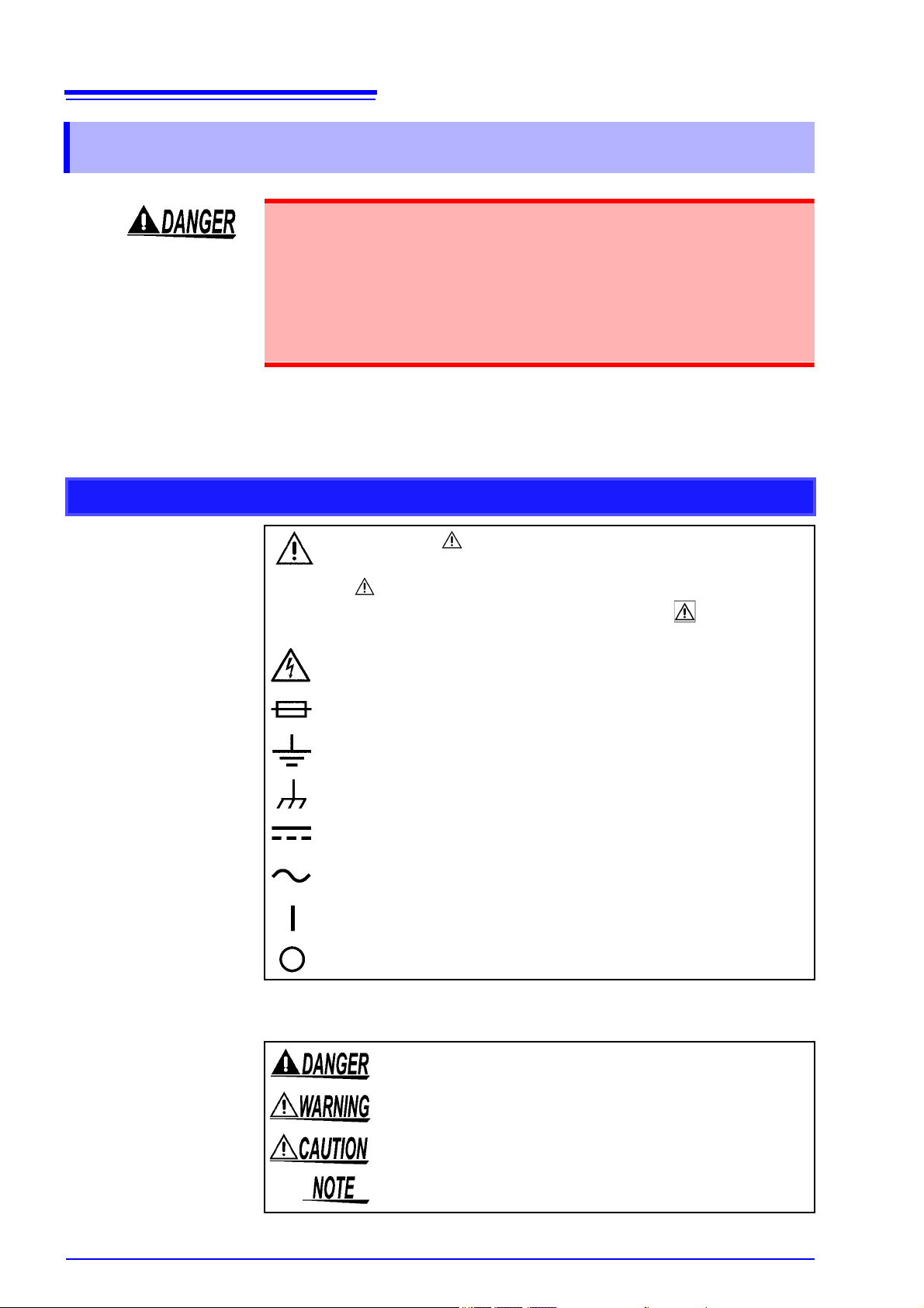
Safety Symbols
In the manual, the symbol indicates particularly important information that
the user should read before using the instrument.
The symbol printed on the instrument indicates that the user should refer
to a corresponding topic in the manual (marked with the symbol) before
using the relevant function.
Indicates that dangerous voltage may be present at this terminal.
Indicates a fuse.
Indicates a grounding terminal.
Indicates a ground terminal connected to the chassis of the system.
Indicates DC (Direct Current).
Indicates AC (Alternating Current).
Indicates the ON side of the power switch.
Indicates the OFF side of the power switch.
The following symbols in this manual indicate the relative importance of cautions
and warnings.
Indicates that incorrect operation presents an extreme hazard that
could result in serious injury or death to the user.
Indicates that incorrect operation presents a significant hazard that
could result in serious injury or death to the user.
Indicates that incorrect operation presents a possibility of injury to the
user or damage to the instrument.
Indicates advisory items related to performance or correct operation
of the instrument.
Page 6
Other symbols
3
Safety Information
Indicates a prohibited action.
*
PAG E
UP
(Bold characters)
(p. #)
Indicates that descriptive information is provided below.
Bold characters within the text indicate operating key labels.
Indicates the location of reference information.
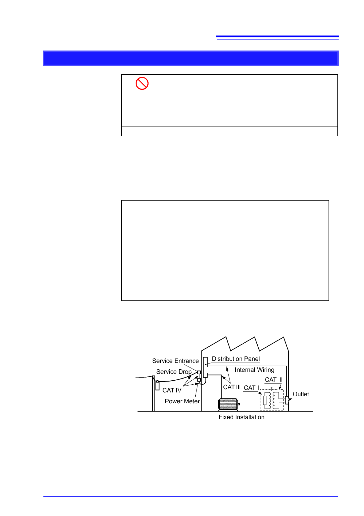
Measurement categories (Overvoltage categories)
To ensure safe operation of measurement instruments, IEC 61010 establishes
safety standards for various electrical environments, categorized as CAT I to
CAT IV, and called measurement categories.
CAT I
CAT II
CAT III
CAT IV
Secondary electrical circuits connected to an AC electrical
outlet through a transformer or similar device.
Primary electrical circuits in equipment connected to an AC
electrical outlet by a power cord (portable tools, household
appliances, etc.)
CAT II covers directly measuring electrical outlet receptacles.
Primary electrical circuits of heavy equipment (fixed
installations) connected directly to the distribution panel, and
feeders from the distribution panel to outlets.
The circuit from the service drop to the service entrance, and
to the power meter and primary overcurrent protection device
(distribution panel).
Using a measurement instrument in an environment designated with a highernumbered category than that for which the instrument is rated could result in a
severe accident, and must be carefully avoided.
Page 7
4
Operating Precautions
Operating Precautions
Follow these precautions to ensure safe operation and to obtain the full benefits
of the various functions.
Preliminary Checks
Before using the instrument for the first time, verify that it operates normally to
ensure that no damage occurred during storage or shipping. If you find any damage, contact your dealer or Hioki representative.
Instrument Installation
Operating temperature and humidity:
0 to 40°C at 80%RH or less (non-condensing)
Temperature and humidity range for guaranteed accuracy:
23±5°C, 80%RH or less (non-condensing)
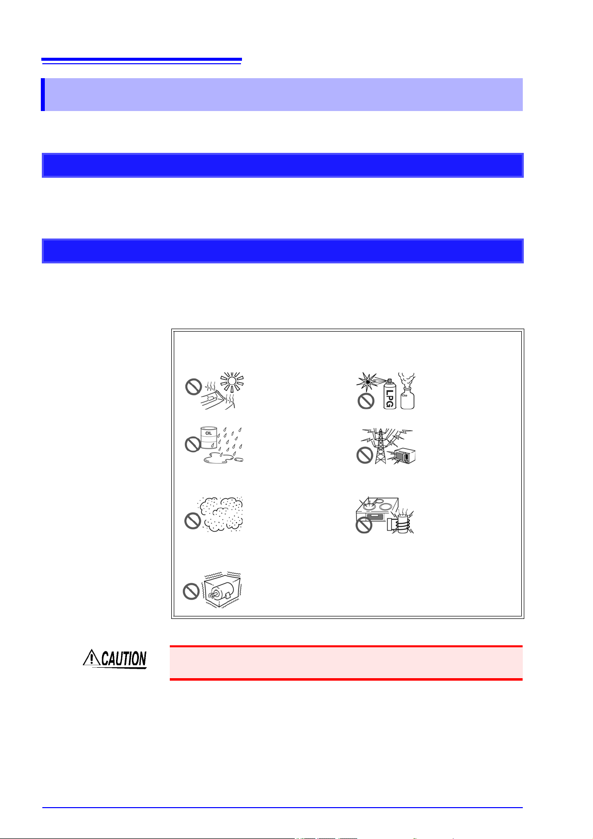
Avoid the following locations that could cause an accident or damage
to the instrument.
Exposed to direct sunlight
Exposed to high temperature
Exposed to water, oil,
other chemicals, or
solvents
Exposed to high humidity or condensation(
Exposed to high levels of particulate dust
Subject to vibration
In the presence of
corrosive or explosive
gases
Exposed to strong
electromagnetic fields
Near electromagnetic
radiators
Near electromagnetic radiators (e.g.,
high-frequency induction heating systems
and IH cooking utensils)
Do not slant the instrument or place it on top of an uneven surface. Dropping or
knocking down the instrument can cause injury or damage to the instrument.
Page 8
Handling the Instrument
• Do not allow the instrument to get wet, and do not take measurements
with wet hands. This may cause an electric shock.
• Touching any of the high-voltage points inside the instrument is very
dangerous. Do not attempt to modify, disassemble or repair the instrument; as fire, electric shock and injury could result.
To avoid damage to the instrument, protect it from physical shock when transporting and handling. Be especially careful to avoid physical shock from dropping.
Handling the Cords
5
Operating Precautions
Before Connecting
Before using the instrument, make sure that the insulation on the Connection Cable is undamaged and that no bare conductors are improperly
exposed. Using the instrument in such conditions could cause an electric
shock, so contact your dealer or Hioki representative for replacements.
• Avoid stepping on or pinching cables, which could damage the cable insulation.
• To avoid breaking the cables, do not bend or pull them.
• To avoid damaging the power cord, grasp the plug, not the cord, when unplugging it from the power outlet.
• Keep the cables well away from heat sources, as bare conductors could be
exposed if the insulation melts.
Use only the specified connection cables. Using a non-specified cable may
result in incorrect measurements due to poor connection or other reasons.
• Before turning the instrument on, make sure the supply voltage matches
that indicated on its power connector. Connection to an improper supply
voltage may damage the instrument and present an electrical hazard.
• To avoid electrical accidents and to maintain the safety specifications of
this instrument, connect the power cord only to a 3-contact (two-conductor + ground) outlet.
Page 9

6
Operating Precautions
Input and Measurement Precautions
• The maximum input voltage and maximum rated voltage to earth are 1000
VDC. If their voltages are exceeded, this instrument will be damaged and
personal injury will result. Therefore, do not input signals in excess of
these values.
• To avoid electrical hazards and damage to the instrument, do not apply
voltage exceeding the rated maximum to the voltage input terminal.
To ensure measurements are accurate,
• Warm up the instrument 60 minutes or more before use.
• The instrument should be calibrated once a year.
Page 10
1.1 Product Overview and Features
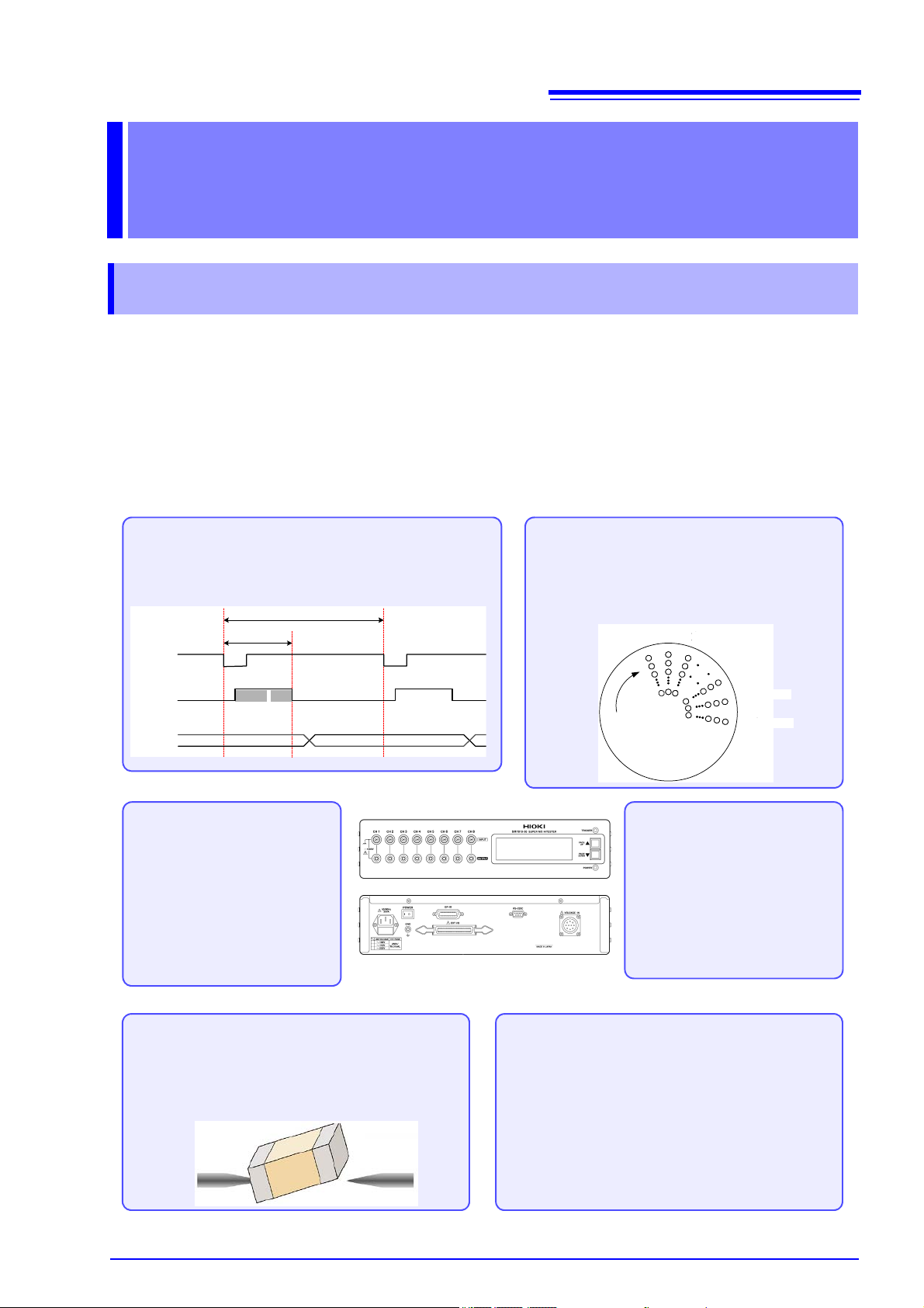
Easy integration into automated testing systems
The instrument features a standard external I/O interface, allowing contact check results and comparison
judgment results to be downloaded to other devices.
Additionally, external I/O can be used to easily change
target objects, making it easy to integrate the instrument into an automated testing system.
High-speed insulation resistance measurement
The instrument is a high-sensitivity ammeter for use in insulation resistance measurement applications. The time
from trigger activation to index output is as little as 7 ms.
TRIG
INDEX
Judgment
7 ms (min)
C.C.
Measu
rement
Machine cycl e
8-channel simultaneous measurement
The instrument can measure 8 channels simultaneously, boosting production volume. This capability improves on previous HIOKI instruments,
which offered 4 channels.
充電3
充電1
充電2
充電n
測定1
測定2
1列
8列
Charge 2
Charge 1
Charge 3
Charge n
Measure 1
Measure 2
Row 1
Row 8
Compatibility with highcapacity capacitors
Range: 100 pA to 1 mA
The instrument features an expanded current measurement
range to accommodate increasingly high-capacity MLCCs, making possible more accurate pass/
fail judgments.
Interface communications
The instrument can be connected to a control device and controlled via either its GP-IB or RS232C interface. Measurement
data can also be downloaded.
Contact check for improved reliability
The instrument can check for poor contact with the object under measurement using the capacitance detection method, and the results of this check can be
output from the instrument.
Overview Chapter 1
1.1 Product Overview and Features
The instrument is an 8-channel, high-sensitivity ammeter for use in measuring
insulation resistance. It can perform insulation measurement of target objects
such as electrical insulators with high resistance values, measuring all 8 channels simultaneously at high speed. The instrument is designed for use in applications such as automatic insulation testing, particularly of capacitors.
This insulation measuring instrument requires an external measurement power
source to be provided by the operator. HIOKI offers a recommended power
source (Model SM7860 series Power Source Unit).
7
Page 11
8
Current-
voltage
converter
A/D
converter
Measuring
interface
Control
unit
EXT I/O
(isolation)
GP-IB
interface
LCD
module
Current-
voltage
converter
A/D
converter
Current-
voltage
converter
A/D
converter
Current-
voltage
converter
A/D
converter
Current-
voltage
converter
A/D
converter
Current-
voltage
converter
A/D
converter
Current-
voltage
converter
A/D
converter
Current-
voltage
converter
A/D
converter
Measuring
interface
INPUT
CH1
CH2
CH3
CH4
INPUT
CH5
CH6
CH7
CH8
OUTPUT
CH1
CH2
CH3
CH4
GUARD
VOLTAGE
INPUT
CH1
CH2
CH3
CH4
CH5
CH6
CH7
CH8
COM
CH5
CH6
CH7
CH8
OUTPUT
Measurement block
Measurement block
A
BC
D
RS-232C
interface
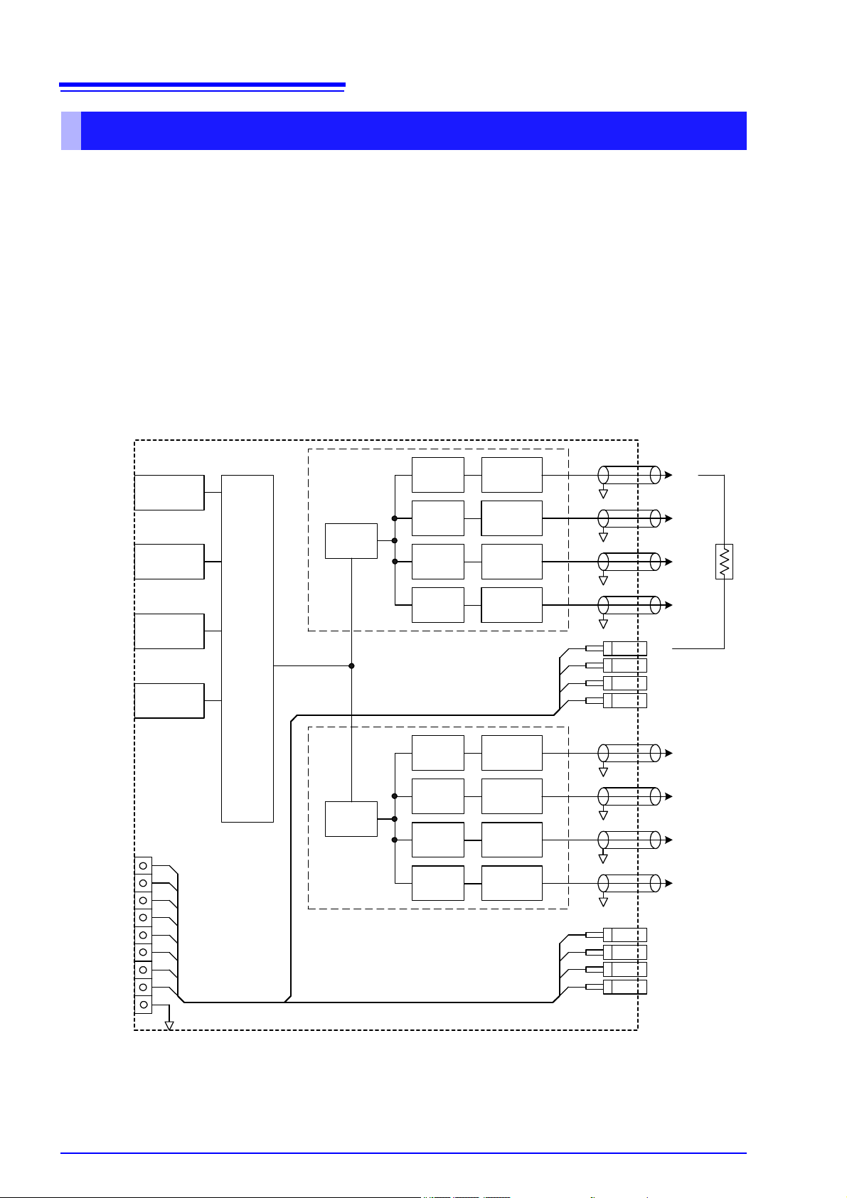
1.1 Product Overview and Features
Operating Principles and Block Diagram
The instrument is an 8-channel, high-sensitivity ammeter for use in measuring insulation resistance. After
connecting the dedicated external power source to the voltage input terminal (A) and applying voltage to the
object under measurement from the voltage output terminals (OUTPUT), current is measured at the current
input terminals (INPUT). The resistance value is then calculated from the measured current values and the
set measurement voltage values.
The measurement block performs current/voltage conversion using charge measurement type current-voltage
converters (B) that integrate input current values and A/D converters (C). This method allows precise measurement of minute currents by using long integration times.
Having been converted into digital data, measurement block output is sent to the control block (D) memory.
The control block (D) performs arithmetic processing on measurement data that has been input to its memory
and sends output to the instrument’s LCD screen and interfaces.
Page 12
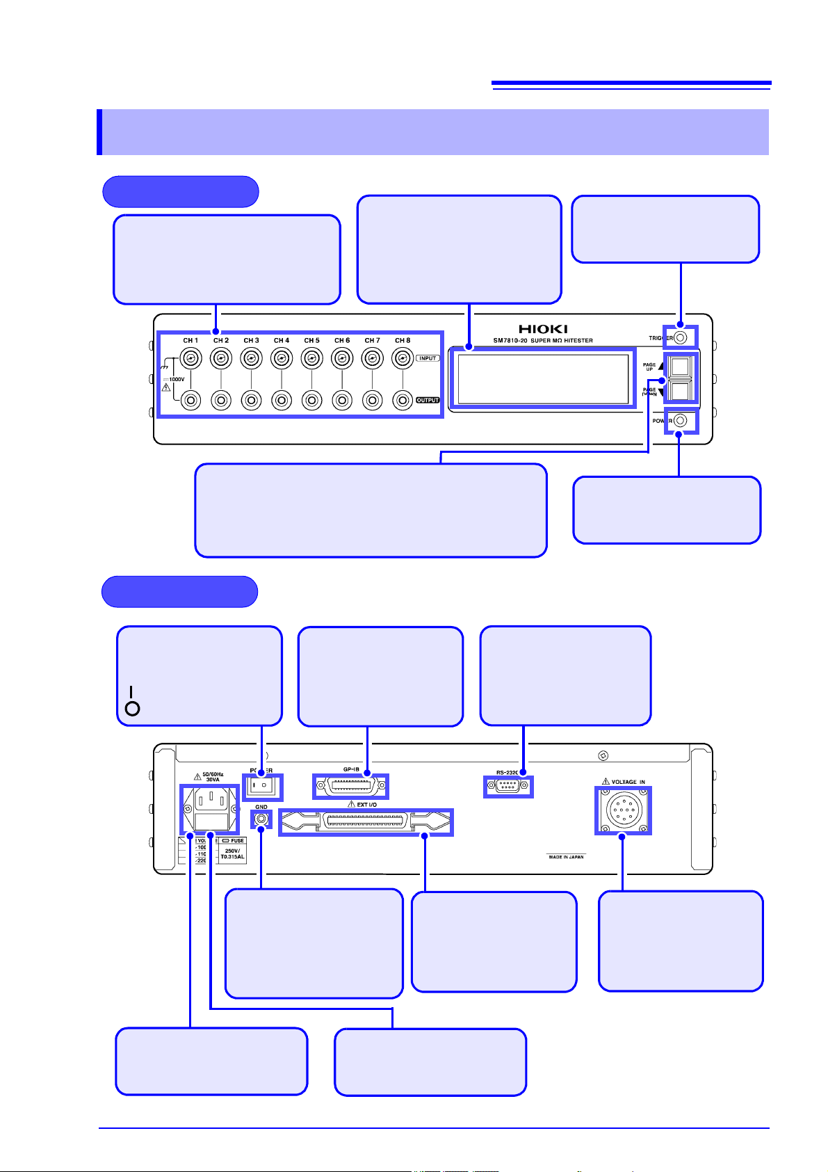
1.2 Names and Functions of Parts
Power indicator
Lights up when the instrument is
on.
Trigger indicator
Lights up when the trigger signal is on.
LCD screen
The instrument’s interface consists
of three display pages, including
measured values, contact check
results, and operating conditions.
"1.3 Screen Layout" (p.10).
Front Panel
Measurement terminals
•
INPUT: Current input terminals
• OUTPUT: Voltage output terminals
The instrument’s 8 channels can be
measured simultaneously.
Scroll keys (PAGE U P ▲/ PA GE DOWN▼)
Used to scroll through the display pages.
"1.3 Screen Layout" (p.10)
The scroll keys are also used to set the GP-IB address.
(p.23)
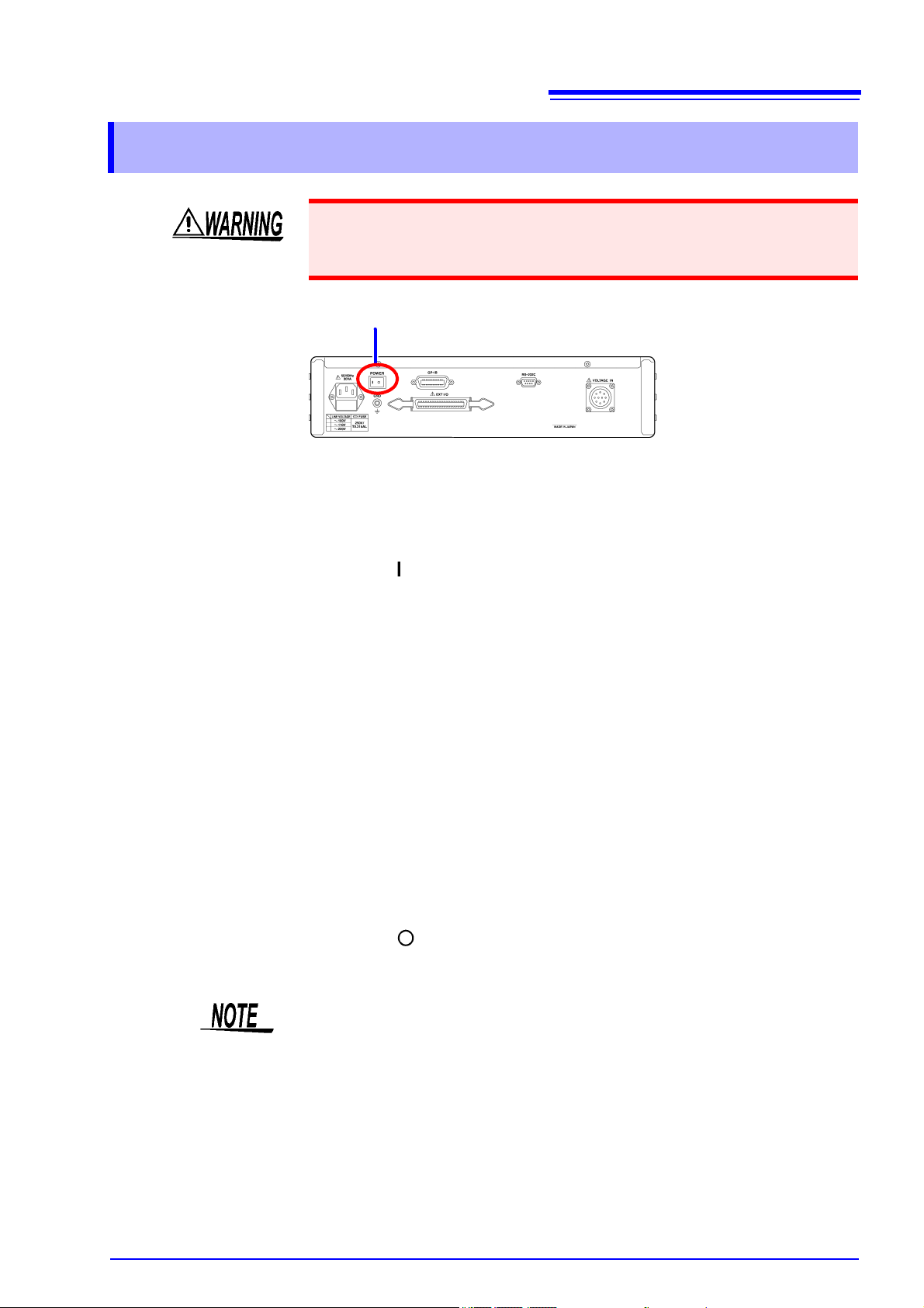
Rear Panel
GND terminal
Serves as the ground terminal.
The GND terminal is connected to the instrument’s enclosure. It is used when shielding
measurement cables.
Power inlet
Connect the supplied power cord
here. (p.12)
POWER switch
Turns the instrument on and
off. (p.15)
: Power On
: Power Off
GP-IB connector
Connect to a computer
when using the GP-IB interface.
(p.21)
RS-232C connector
Connect to a computer when
using the RS-232C interface.
(p.21)
EXT I/O connector
The external I/O connector
can be used to control the
instrument.
(p.41)
Voltage input terminal
Supplies the measurement
power source. Connect the
included voltage input connector.
Fuse holder
Allows the fuse to be replaced.
(p.60)
1.2 Names and Functions of Parts
9
Page 13
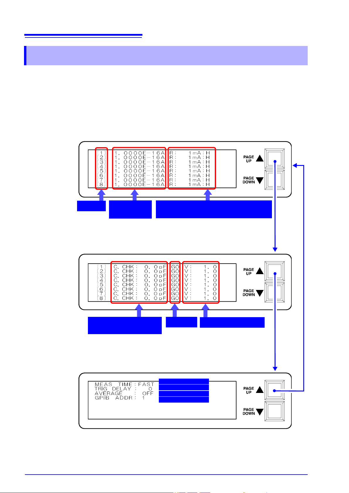
10
■ Screen P1: Measured value display
■ Screen P2: Contact check results display
■ Screen P3: Operating condition display
Measurement speed
Trigger delay time
Averaging settings
Contact-check
measurement values
Judgment
Measurement voltage
Measurement
values
GP-IB address
Channel
Measurement range: A (Auto range)
: H (Fixed range)
1.3 Screen Layout
1.3 Screen Layout
The LCD screen consists of three display pages. When the instrument is turned
on, page 1 is shown. The scroll keys on the front of the instrument (PAGE U P ▲/
PAG E DOWN▼) are used to scroll among the display pages, which can also be
selected directly by sending the “
interface.
See: Message List "PAG" (p.38)
PAG” command from the GP-IB or RS-232C
Page 14
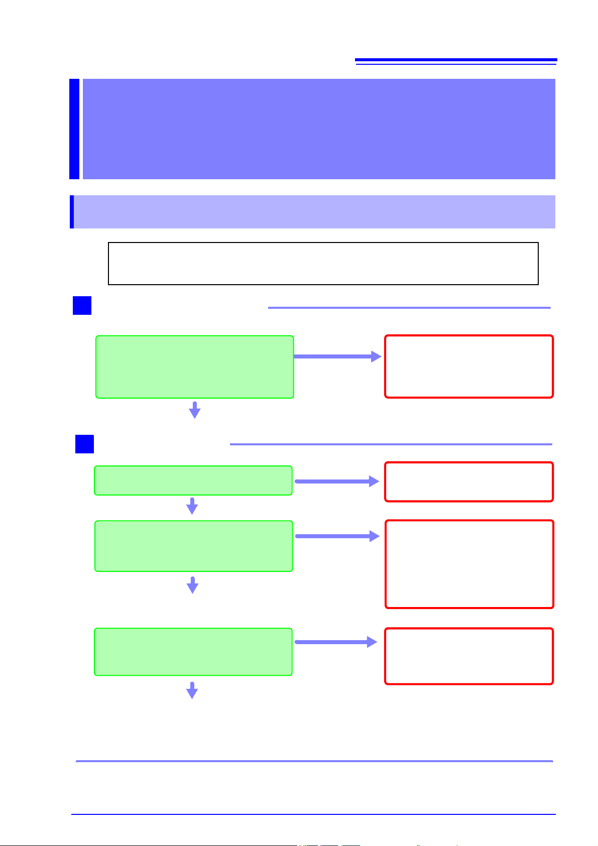
11
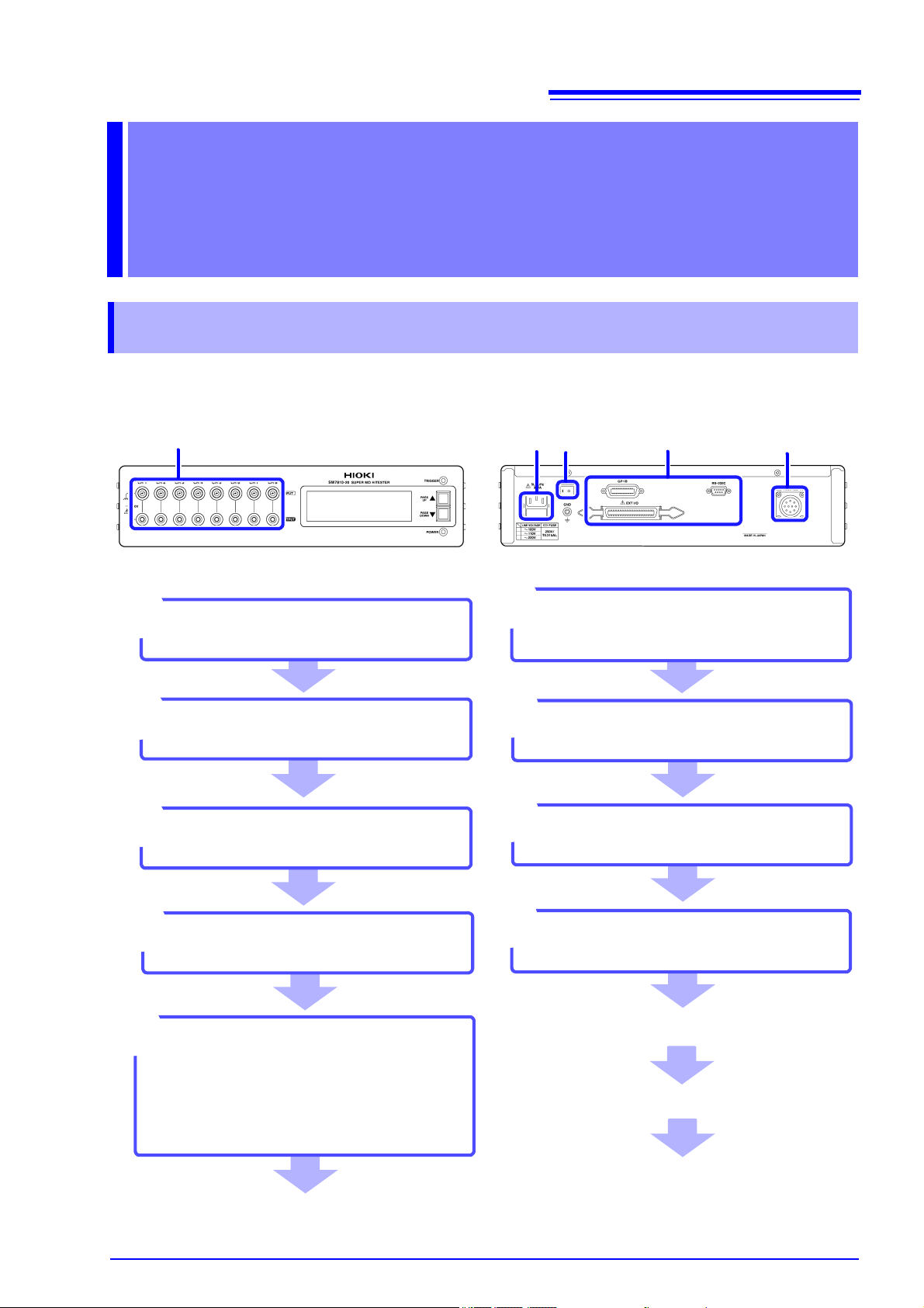
Connect to the test sample
9
Install this instrument (p.4)
1
Rear PanelFront Panel
Connect measurement cables
(p.13)
Turn the power on (p.15)
7
Connect the external interface
(as needed)
5
• Using the GP-IB or RS-232C interface
(p.19)
• Using the EXT I/O (p.41)
Connect the power cord (p.12)
2
3
2
3
5
Make instrument settings (p.18)
(via the external interface)
8
Connect the instrument to the
measurement line (p.14)
4
Be sure to complete the pre-operation inspection (p.17) before
starting measurement
6
When finished measuring,
turn the power off (p.15)
4
Activate the measurement
power source
Make measurements
7
2.1 Installation & Connection Procedures
Measurement
Preparations Chapter 2
2.1 Installation & Connection Procedures
Be sure to read the "Operating Precautions" (p.4) before installing and connecting
this instrument.
Page 15
12
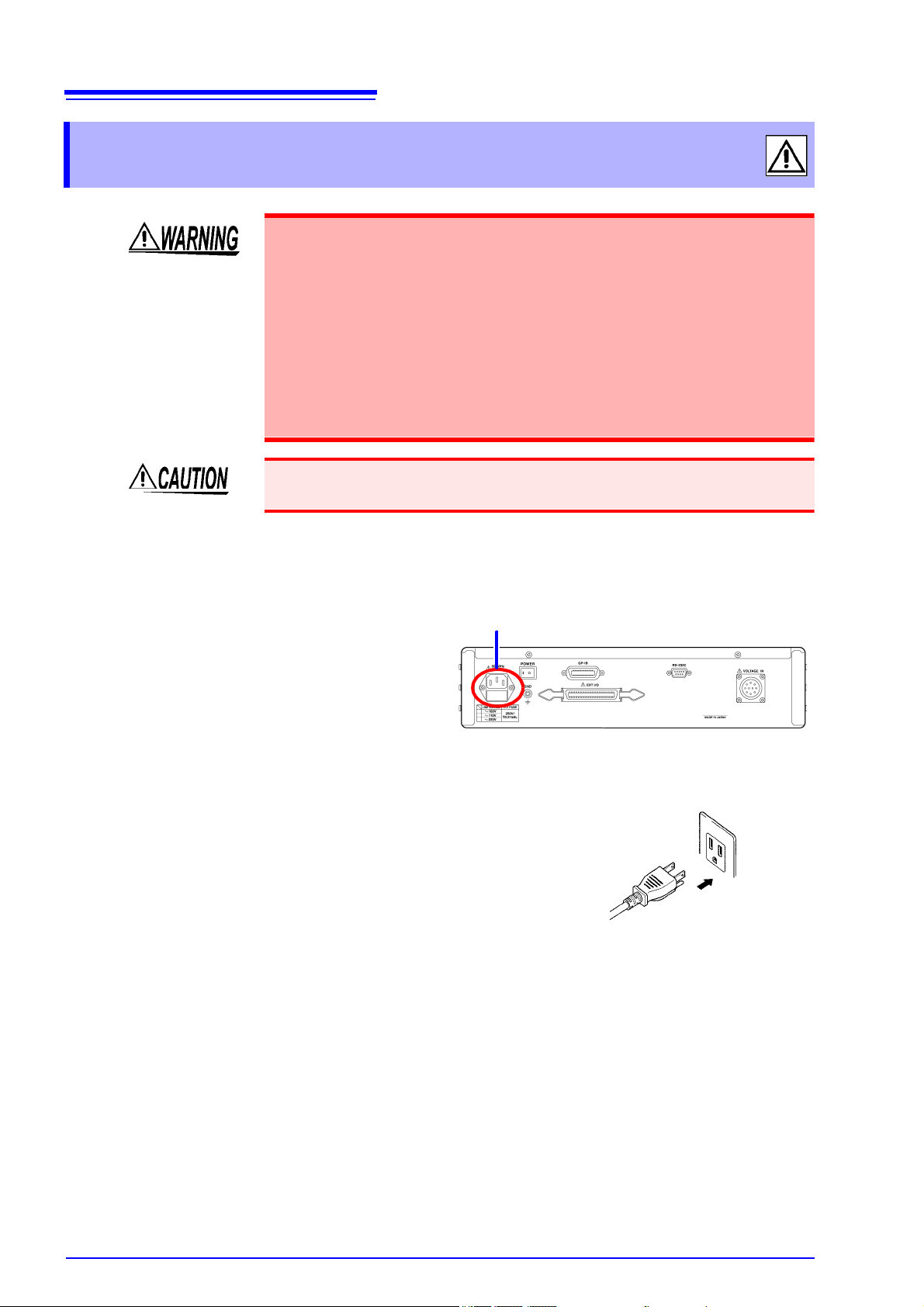
Rear Panel
1 Confirm that the instrument is turned
off.
2 Confirm that the mains supply volt-
age matches the instrument, and
connect the power cord to the power
inlet on the instrument.
3 Plug the power cord into the mains
outlet.
Power inlet
2.2 Connecting the Power Cord
2.2 Connecting the Power Cord
• Before turning the instrument on, make sure the supply voltage matches
that indicated on its power connector. Connection to an improper supply
voltage may damage the instrument and present an electrical hazard.
• To avoid electrical accidents and to maintain the safety specifications of
this instrument, connect the power cord only to a 3-contact (two-conductor + ground) outlet.
• Before using the instrument, make sure that the insulation on the power
cord is undamaged and that no bare conductors are improperly exposed.
Using the instrument in such conditions could cause an electric shock,
so contact your dealer or Hioki representative for replacements.
To avoid damaging the power cord, grasp the plug, not the cord, when unplugging it from the power outlet.
Turn off the power before disconnecting the power cord.
Connection Methods
Page 16
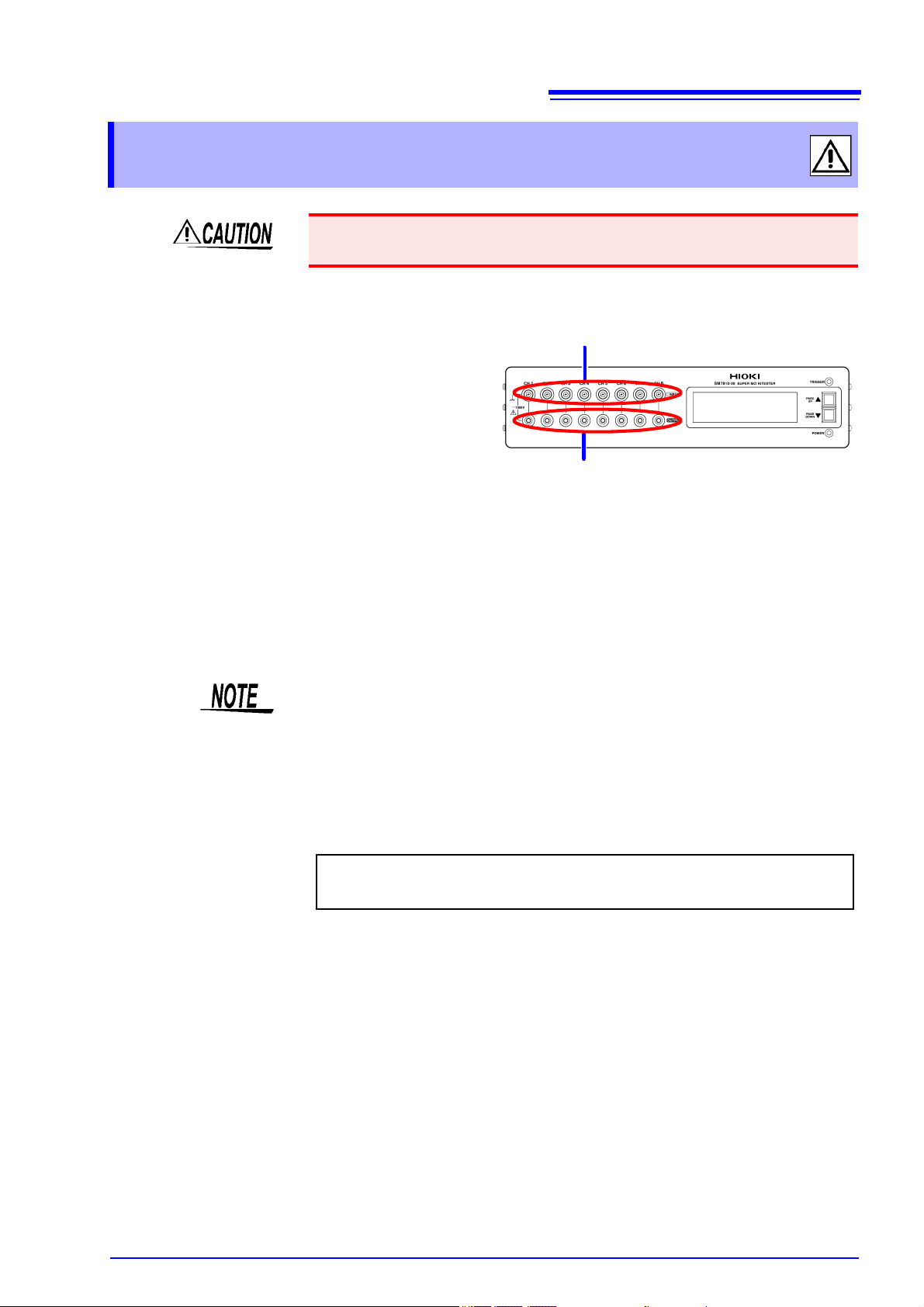
2.3 Connecting the Measurement Cables
Front panel
1 Connect the measurement cables to
each channel’s current input terminal.
2 Connect the voltage output cables to
each channel’s voltage output terminal.
Current input terminals
Voltage output terminals
For more information about measurement cables and voltage output cables,
please contact your dealer or HIOKI representative.
2.3 Connecting the Measurement Cables
To avoid damage to the instrument, do not apply voltage to measurement terminals.
Connection Methods
13
• The current input terminals incorporate a two-tiered design with both center
and outer conductors. The center conductors are connected to measurement
input, while the outer conductors are connected to guard signals.
• Because the instrument performs high-sensitivity current measurement, noise
occurring on the measurement cables may prevent measured values from stabilizing. Use low-noise shielded measurement cables that meet HIOKI’s specifications.
Page 17
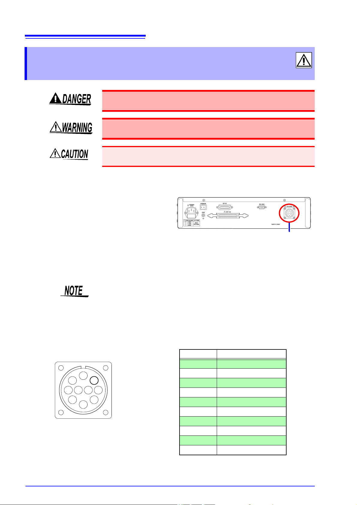
14
Rear Panel
1 Confirm that the instrument is turned
off.
2 Connect the included voltage input
connector to the voltage input terminal on the rear of the instrument.
Voltage input terminal
6 5 47
3
2
10
8
9
1
Voltage input pin assignments
(View of terminal on instrument)
Pin No. Channel
1 CH1
2 CH2
3 CH3
4 CH4
5 CH5
6 CH6
7 CH7
8 CH8
9 NC
10 COM
2.4 Connecting the Measurement Power Source
2.4 Connecting the Measurement Power
Source
To avoid electrical hazards and damage to the instrument, do not apply
voltage exceeding the rated maximum to the voltage input terminal.
Do not input voltage to the voltage input terminal before connecting measurement cables and voltage output cables. Doing so may result in injury.
When the power is turned off, do not apply voltage to the voltage input terminals.
Doing so may damage the instrument.
Connection Methods
This insulation measuring instrument requires an external measurement power
source provided by the operator. HIOKI offers a recommended power source
(Model SM7860 series Power Source Unit).
Specifications
Page 18
2.5 Turning the Power On and Off
Rear Panel
POWER switch
Turn the POWER switch on ( ).
The power indicator and LCD screen on the front of the instrument will light up.
When the power is turned on, the same setting as when the power was last turned off appears
(backup function).
When powered up for the first time, the instrument will be configured with its default settings.
However, the LCD screen is not backed up.
Before Starting Measurement
To obtain precise measurements, provide about 60 minutes warm-up after turning power on.
Before turning the instrument off, turn off measurement power source output.
Turn the POWER switch off ( ).
2.5 Turning the Power On and Off
Before turning the instrument on, make sure the supply voltage matches
that indicated on its power connector. Connection to an improper supply
voltage may damage the instrument and present an electrical hazard.
15
Turning Power On
Turning Power Off
If a power outage (e.g., breaker trip) occurs when the instrument is on, it will
automatically turn on again when power is restored.
Page 19

16
2.5 Turning the Power On and Off
Page 20
3.1 Pre-Operation Inspection
Do not use a damaged cord because
doing so may result in electric
shock. (Replace the cord with a new
one.)
Metal Exposed
• Is the power cord insulation torn, or is
any metal exposed?
• Is the connection cord insulation torn, or
is any metal exposed?
1
No Metal Exposed
Before using the instrument the first time, verify that it operates normally to ensure that the
no damage occurred during storage or shipping. If you find any damage, contact your dealer
or Hioki representative.
Peripheral Device Inspection
If damage is evident, request repairs.
Yes
Is damage to the instrument evident?
When turning power on
Do the “HIOKI”, “SM7810” and version number indications appear on the display area?
No
2
The power cord may be damaged, or
the instrument may be damaged internally.
Request repairs.
No
Yes
Inspection complete
Please read the "Operating Precautions" (p.4) before use.
Use of a supply voltage outside the
specified range may damage the instrument or cause electric shock.
Before turning the instrument on,
make sure the supply voltage
matches that indicated on its power
connector.
No
Does the supply voltage of your power
source match the supply voltage indicated
above the power source inlet on the rear of
the instrument?
Yes
Instrument Inspection
Setting Measurement
Conditions Chapter 3
3.1 Pre-Operation Inspection
17
Page 21

18
3.2 Setting Measurement Conditions
3.2 Setting Measurement Conditions
This section describes how to set measurement conditions according to the
manner in which the instrument is to be used. Settings are configured via either
of the instrument’s external interfaces:
See: GP-IB/RS-232C Interface (p.19)
The instrument cannot be configured directly in a standalone manner. For more
detailed setting specifications, see "6.3 Functions" (p.51).
Setting
function
Measurement
value indication
Measurement
speed
Current
measurement
range
Trigger delay
time
Averaging
Power source
frequency
Measurement
voltage
Fixture capacitance open correction function
Contact-check
Measured value
comparison/
judgment function
Fixture resistance open correction function
LCD display
mode
Description of operation and settings For more
Selects the displayed value.
[Resistance * / Current]
* Resistance is calculated from the set measurement voltage and current
value.
Selects the measurement speed.
[FAST / MED (medium) / SLOW / SLOW2]
Switches the current measurement range.
[HOLD/ AUTO]
Selects the current measurement range.
[100 pA/ 1 nA/ 10 nA/ 100 nA/ 1 μA/ 10 μA/ 100 μA/ 1 mA]
Fix time between inputting trigger signal and starting measurement.
0 ms to 9999 ms (1 ms resolution)
Configures averaging of measured values.
OFF (No averaging) / ON (Required setting number of times for averaging) / AUTO (Number of times for averaging is automatically determined)]
Number of times (in case “ON” setting): 1 to 255
Selects the power source frequency.
[50/60 Hz]
Sets the measurement voltage.
Setup ranges: 0.1 to 1000.0 V (0.1 V resolution)
Measures the capacitance value with the fixture in the open state.
The fixture capacitance open correction function can be used to increase
measurement precision by decreasing the effects of residual inductance of
the fixture (including probes) and other components.
Judges whether the object under measurement is connected by performing capacitance measurement with a high-frequency signal and evaluating
the difference between that reading and the reading obtained when the
system is in the open state.
[OFF/ ON]
Judgment GO: Capacitance measured value > judgment reference value *
NG: Judgment reference value * ≥ capacitance measured value
* Judgment reference value = Fixture capacitance + (object under mea-
surement capacitance setting / 2)
Compares the measured value and reference value to make a PASS/FAIL
judgment.
[OFF/ ON]
Judgment HI : Measured value > upper limit setting
IN : Upper limit setting ≥ measured value ≥ lower limit setting
LO: Lower limit setting > measured value
Measures the current of the fixture in the open state and corrects measured values.
[OFF/ ON]
Turns the LCD display on and off.
[OFF/ ON]
information
(p.33)
(p.33)
(p.34)
(p.34)
(p.34)
(p.34)
(p.35)
(p.37)
(p.43)
(p.36)
(p.43)
(p.37)
(p.46)
(p.37)
(p.43)
(p.38)
Page 22

19
Wiring Diagram (p.21)
Connect the Instrument and
Controller with a GP-IB or RS232C Interface Cable
Communications Protocol Settings
Enter a GP-IB address. (p.23)
Set the instrument to the same
communications protocol as the
controller
Send the “
RMT” command. (p.23)
4.1 Overview and Features
Communication
(GP-IB/RS-232C Interface) Chapter 4
The symbol shown below indicates that the following instructions are specific to
the RS-232C or the GP-IB interface. Instructions without these symbols are for
both the RS-232C and the GP-IB interface.
: GP-IB only
: RS-232C only
Before Use • Always make use of the connector screws to affix the GP-IB or RS-232C con-
nectors.
• When issuing commands that contain data, make certain that the data is provided in the specified format.
4.1 Overview and Features
The instrument provides standard communication functionality in the form of GPIB and RS-232C interfaces, both of which can be used to control the instrument
remotely and to transfer data.
• This instrument is designed with reference to the following standard:
Reference standard IEEE 488.1-1987
Page 23

20
4.2 Specifications
4.2 Specifications
Precautions
RS-232C and GP-IB communications cannot be used simultaneously.
GP-IB Specifica-
tions
Electrical machinery specifications: IEEE std. 488.1-1987 compliant
Address setting : Can be set to talker/listener addresses 1 to 30.
Interface Functions
SH1 All Source Handshake functions ●
AH1 All Acceptor Handshake functions ●
T6 Basic talker functions
Serial poll function
Talk-only mode
The talker cancel function with MLA (My Listen Address)
L4 Basic listener functions
Listen-only mode
The listener cancel function with MTA (My Talk Address)
SR1 All Service Request functions ●
RL1 All Remote/Local functions ●
PP0 Parallel Poll function −
DC1 All Device Clear functions ●
DT1 All Device Trigger functions ●
C0 Controller functions −
E2 Tri-state output
Operating Code: ASCII codes
●
●
−
●
●
−
●
RS-232C Specifica-
tions
Transfer method Communications: Full duplex
Synchronization: Start-stop synchronization
Baud rate 38400 bps
Data length 8 bits
Parity none
Stop bit 1 bit
Flow control none
Electrical specification Input voltage levels 5 to 15 V : ON
-15 to -5 V : OFF
Output voltage levels +5 V or more : ON
-5 V or less : OFF
Connector RS-232C Interface Connector Pinout
(Male 9-pin D-sub, with #4-40 attachment screws)
The I/O connector is a DTE (Data Terminal Equipment)
configuration
Recommended cables:
• Model 9637 RS-232C Cable
• Model 9638 RS-232C Cable
See: "4.3 Connect a cable to the GP-IB connector or
RS-232C connector" (p.21)
Operating Code: ASCII codes
Page 24

4.3 Connect a cable to the GP-IB connector or RS-232C connector
Rear Panel
Recommended cable:
HIOKI Model 9151-02 GP-IB Connector Cable (2 m)
6 7 8 9
1 2 3 4 5
Rear Panel
Male 9-pin D-sub
#4-40 attaching screws
4.3 Connect a cable to the GP-IB
connector or RS-232C connector
• Always turn both devices OFF when connecting and disconnecting an
interface connector. Otherwise, an electric shock accident may occur.
• Failure to fasten the connectors properly may result is sub-specification
performance or damage to the equipment.
To avoid damage to the instrument, do not short-circuit the terminal and do not
input voltage to the terminal.
Using the GP-IB Interface
21
Connect the GP-IB cable to the GP-IB connector.
Using the RS-232C Interface
Connect the RS-232C cable to the RS-232C connector.
Pin No.
1 DCD CF CD
2 RXD BB RD
3 TXD BA SD
4DTRCD ER
5 GND AB SG
6DSRCC DR
7 RTS CA RS
8 CTS CB CS
9 RI CE CI
Signal
Name
Code Addr.
EIA JIS
Mutual connection
circuit name
Carrier Detect Not used
Receive Data
Transmit Data
Data Terminal Ready Not used
Signal Ground
Data Set Ready Not used
Request to Send Not used
Clear to Send Not used
Ring Indicator Not used
Remarks
Page 25

22
Recommended cable:
HIOKI
Model 9637 RS-232C
Cable (1.8 m)
Crossover Wiring
Female 9-pin
D-sub
Model SM7810,
SM7810-20 end
Female 9-pin
D-sub
PC/AT-end
Pin No. Pin No.
DCD 1 1 DCD
RxD 2 2 RxD
TxD 3 3 TxD
DTR 4 4 DTR
GND 5 5 GND
DSR 6 6 DSR
RTS 7 7 RTS
CTS 8 8 CTS
RI 9 9 RI
4.3 Connect a cable to the GP-IB connector or RS-232C connector
When connecting the instrument to a computer
Use a crossover cable with female 9-pin D-sub connectors.
Page 26

4.4 Configuring the Communications Protocol
1 Press and hold the scroll keys (PAG E U P▲/PA GE D OW N ▼) on the front of the instru-
ment for about 7 seconds. (The address can be set from the P1, P2, or P3 screen.)
■ Screen P1: Measured value display
3 When finished making the setting, turn off the instrument.
4 Turn on the instrument.
The instrument will revert to the initial screen, and the GP-IB address will be set to
the selected address.
2 Using the scroll keys (PAGE UP▲/PAGE DOWN▼), set the desired address.
(Valid setting range: 1 to 30)
4.4 Configuring the Communications Protocol
Configuring GP-IB Interface Communications
Setting the address
23
Configuring RS-232C Interface Communications
Communication conditions
Baud rate 38400 bps
Parity none
Stop bit 1 bit
Data 8 bits
Flow control none
Remote switching requests
Send the “RMT” command from the RS-232C interface.
RS-232C interface communications will not be available until the “RMT” command is sent.
Page 27

24
Program Messages
Response Messages
SM7810
SM7810-20
Program Messages
Messages
Command Message
Query Message
Response Message
Controller
Message types are further categorized as follows
When issuing commands that contain data, make certain that the data is provided in the specified format.
4.5 Communication Methods
4.5 Communication Methods
Various messages are supported for controlling the instrument through the interfaces.
Messages can be either program messages, sent from the controller such as PC to the
instrument, or response messages, sent from the instrument to the controller.
Program Messages
1. Command Messages and Query Messages
(1) Command Messages
Commands that control the instrument, for example to configure settings or reset
the device.
(2) Query Messages
Requests for responses relating to results of operation or measurement, or the
state of instrument settings.
Query commands end with a question (
2. Message delimiter (terminator)
This instrument recognizes the following input message delimiters:
CR+LR with EOI
LF with EOI
CR with EOI
EOI
CR+LF
LF
?) mark.
Response Messages
1. Response Messages
When a query message is received, its syntax is checked and a response message is generated.
2. Message delimiter (terminator)
The following three response message delimiters can be specified with the
“
DLM” command:
LF (initial setting)
CR+LF
EOI
Page 28

3. Measurement data format
1,±d.ddddE±dd,d,d,2,±d.ddddE±dd,d,d,
abcdab cd
3,±d.ddddE±dd,d,d,4,±d.ddddE±dd,d,d,
abcdab cd
5,±d.ddddE±dd,d,d,6,±d.ddddE±dd,d,d,
abcdab cd
7,±d.ddddE±dd,d,d,8,±d.ddddE±dd,d,d
abcdab cd
LF <EOI>
e
±d.ddddE±dd
d: Number
When the range is exceeded, all numbers in the output data are set to 9 (for resistance
measurements) or 0 (for current measurements).
9.9999E+99
+0.0000E+00
Resistance measurement
Current measurement
A status of 0 indicates normal operation.
When comparative measurement is off, comparison results (d) are not added to the
output data.
The data format returned by the “MTG” and “RDT?” commands can be set to
any of the following three types by command:
(1) Basic format
Data is returned in channel order.
Fields are separated by a data separator (
25
4.5 Communication Methods
,).
a. Channel number
The channel number is set as a 1-byte number from 1 to 8.
b. Measured value
The measured value is set as an 11-byte exponent.
c. Status
The contact check and range exceeded results are set as numbers from 0 to 4. The results are allocated to bits 0 to 2 of the status, and their logical sum is output.
Bit 0: 0 (fixed)
Bit 1: Contact check error (automatic execution result)
Bit 2: Range exceeded
d. Comparison result
When comparative measurement is on, this field is set to the result (0 to 2).
0: High (The measured value was greater than the upper limit reference value.)
1: IN (The measured value fell within the range defined by the upper and lower limits.)
2: LOW (The measured value was less than the lower limit reference value.)
e. Delimiter
The output message delimiter can be specified with the “
DLM” command.
Page 29

26
4.5 Communication Methods
(2) Measured value only
The status (c) and comparison results (d) are not added to the output data.
Otherwise, this format is the same as the basic format.
(3) Comparison results only
The measured value (b) and status data (d) are not added to the output data.
Otherwise, this format is the same as the basic format.
Separators
1. Message Unit Separator
Multiple message can be written in one line by separating them with semicolons
“
; ”
2. Header Separator
3. Data Separator
Data Formats
In a message consisting of both a header and data, the header is separated from
the data by a space “ ” (ASCII code 20H).
In a message containing multiple data items, commas are required to separate
the data items from one another.
Query messages use the formats outlined in Table 1. The format is selected
according to the command.
Table 1: Response Messages and Parameter Data Types
Data
type
NR1 Integer 0, 1, 2, 3, etc. Parameter settings, etc.
NR2
NR3
ASCII ASCII string XXXXXXXXXXXXXXXX Primarily hardware IDs
Description Example Notes
Fixed-point decimal number
Floating-point decimal number
+12.345, 400.0, etc. Primarily settings
+1.234±50, etc.
Primarily settings and measured values
Page 30

Status Byte Register
bit 7bit 6bit 5bit 4bit 3bit 2bit 1bit 0
ERR
RQS
ESB MAV DSB
unused unused
unused
MSS
& &&&&&&
bit 7bit 6bit 5bit 4bit 3bit 2bit 1bit 0
ERR x ESB MAV DSB
unused unused
unused
Logical
sum
Status Byte
Register (STB)
Service Request Enable
Register (SRER)
Service Request
occurrence
Output Queue data information
Standard Event Register Information
Each of these bits corresponds to a specific event register
Overview of Service Request Occurrence
RS-232C reads the status bytes to find out the status of the instrument.
The instrument adopts the IEEE488.1-1987 defined status model for parts
related to the serial polling performed by the service request function. A trigger
for generating a service request is called an event.
27
4.5 Communication Methods
The Status Byte Register contains information about the event registers and the
output queue. Required items are selected from this information by masking with
the Service Request Enable Register. When any bit selected by the mask is set,
bit 6 (MSS; the Master Summary Status) of the Status Byte Register is also set,
which generates an SRQ (Service Request) message and dispatches a service
request.
For RS-232C, bit 4 (MAV message available) of the status byte register is not
set.
Page 31

28
4.5 Communication Methods
Status Byte Register (STB) ______________________________________
A status byte register is an 8-bit register output from the unit to the controller during serial polling. If even one of the status byte register bits enabled by the service request enable register changes from "0" to "1" the MSS bit becomes 1. At
the same time, the RQS bit also becomes "1" and a service request is generated.
The RQS bit is always synchronized with the service request and only read and
simultaneously cleared upon being serial polled. The MSS bit is only read by an
"*
STB?" query and is not cleared until the event is cleared by a command such
as a "*
CLS" command.
Bit 7 ERR
Bit 6 RQS
MSS
Bit 5 ESB
Bit 4 MAV
Bit 3 DSB
Bit 2 −
Bit 1 −
Bit 0 −
Unrecoverable error
Set to 1 when a service request is dispatched.
This is the logical sum of the other bits of the Status Byte Register.
Standard Event Status (logical sum) bit
This is logical sum of the Standard Event Status Register.
Message available
Indicates that a message is present in the output queue.
Event Status (logical sum) bit
This is the logical sum of Event Status Register.
unused
unused
unused
Service Request Enable Register (SRER) __________________________
This register masks the Status Byte Register. Setting a bit of this register to 1
enables the corresponding bit of the Status Byte Register to be used.
Page 32

29
4.5 Communication Methods
Event Registers
Standard Event Status Register (SESR) ____________________________
A standard event status register is an 8-bit register.
If any bit in the Standard Event Status Register is set to 1 (after masking by the
Standard Event Status Enable Register), bit 5 (ESB) of the Status Byte Register
is set to 1.
See: "Standard Event Status Enable Register (SESER)" (p.30)
The standard event register is cleared at the following times:
• When a "
• When an event register query (
• When the instrument is powered on
*CLS" command is executed
*ESR?) is executed
Bit 7 PON
Bit 6 URQ
Bit 5 CME
Bit 4 EXE
Bit 3 DDE
Bit 2 QYE
Bit 1 RQC
Bit 0 OPC
Power-On Flag
Set to 1 when the power is turned on, or upon recovery from an outage.
User Request
unused
Command error (The command to the message terminator is ignored.)
This bit is set to 1 when a received command contains a syntactic or semantic
error:
• Program header error
• Incorrect number of data parameters
• Invalid parameter format
• Received a command not supported by the instrument
Execution Error
This bit is set to 1 when a received command cannot be executed for some
reason.
• The specified data value is outside of the set range
• The specified setting data cannot be set
• Execution is prevented by some other operation being performed
Device-Dependent Error
This bit is set to 1 when a command cannot be executed due to some reason
other than a command error, a query error or an execution error.
• When the command cannot be executed because there is an internal
anomaly
Query Error (the output queue is cleared)
This bit is set to 1 when a query error is detected by the controller of the output
queue.
• When an attempt has been made to read an empty output queue (GP-IB
only)
• When the data overflows the output queue
• When data in the output queue has been lost
Request Control
unused
Operation Complete
This bit is set to 1 in response to an "
• It indicates the completion of operations of all messages up to the "*OPC"
command
*OPC" command.
Page 33

30
bit 7bit 6bit 5bit 4bit 3bit 2bit 1bit 0
PON URQ CME EXE DDE QYE RQC OPC
&&&&&&&&
bit 7bit 6bit 5bit 4bit 3bit 2bit 1bit 0
PON URQ CME EXE DDE QYE RQC OPC
Standard Event Status Register (SESR)
Standard Event Status Enable Register (SESER)
bit 6bit 5bit 4
SRQ
MSS
ESB MAV
Logical
sum
4.5 Communication Methods
Standard Event Status Enable Register (SESER) ____________________
Setting any bit of the Standard Event Status Enable Register to 1 enables
access to the corresponding bit of the Standard Event Status Register.
Standard Event Status Register (SESR) and Standard Event Status Enable
Register (SESER)
Device Event Status Registers (DESR)_____________________________
This instrument provides specific event status registers for controlling events.
Each event register is an 8-bit register.
When any bit in one of these event status registers enabled by its corresponding
event status enable register is set to 1, bit (DSB) of the Status Byte Register is
set to 1.
Device Event Status Registers are cleared in the following situations:
• When a "
• When an Event Status Register query (
• When the instrument is powered on
Bit 7 − Unused
Bit 6 − Unused
Bit 5 BOV Reserved bit
Bit 4 BFL Reserved bit
Bit 3 STP Measured stop event
Bit 2 ITL Reserved bit
Bit 1 LM2 Reserved bit
Bit 0 LM1 Reserved bit
*CLS" command is executed
DSR?) is executed
Page 34

31
bit 7bit 6bit 5bit 4bit 3bit 2bit 1bit 0
−−
BOV BFL STP ITL LM2 LM1
&&&&&&&&
bit 7bit 6bit 5bit 4bit 3bit 2bit 1bit 0
−−
BOV BFL STP ITL LM2 LM1
Device Event Status Enable Register (DESER)
bit 3
DSB
Status Byte Register (STB)
Logical
sum
Device Event Status Register (DESR)
4.5 Communication Methods
Device Event Status Register (DESR) and Device Event Status Enable Register (DESER)
Page 35

32
bit 7bit 6bit 5bit 4bit 3bit 2bit 1bit 0
− MLE
HDE DFE DRE CNE ISE BDE
Error Register
PON URQ CME EXE DDE QYE RQC OPC
Standard Event Status Register
bit 7bit 6bit 5bit 4bit 3bit 2bit 1bit 0
MLE: Message Length Error HDE: Header Error
DFE: Data Format Error DRE: Data Range Error
CNE: Can Not Execute ISE: Internal communication Error
BDE: Environment Backup was Damaged (RAM)
Error Register structure
4.5 Communication Methods
Error Registers
The Error Register, which consists of 8 bits, manages error information. The
contents of this register are aggregated in the CME, EXE, DDE, and QYE bits of
the Standard Event Status Register (no mask processing is performed).
Error register-related message are listed below.
*CLS
ERR?
Clears the following registers:
• Status Byte Register
• Standard Event Status Register
• Device Event Status Register
• Error Register
Queries and clears the Error Register.
Bit No. Name Event/status indicated by set bit
Bit 7 −
Bit 6 MLE
Bit 5 HDE
Bit 4 DFE
Bit 3 DRE
Bit 2 CNE
Bit 1 ISE
Bit 0 BDE
Unused
Message Length Error
Set when the message length exceeds the allowable range.
The bit is reset after the register is read.
Message Header Error
Set when an unrecognizable message header is received.
The bit is reset after the register is read.
Data Format Error
Set when the number of parameters exceeds the stipulated number or
when there is an unrecognizable parameter.
The bit is reset after the register is read.
Data Range Error
Set when a parameter falls outside the stipulated range.
The bit is reset after the register is read.
Unexecutable command
Set when an unexecutable command is received.
The bit is reset after the register is read.
Internal communication Error
Set when an internal communication error occurs.
The bit is reset after the register is read.
Environment Backup was Damaged
Set when data stored in the instrument's backup RAM is corrupted.
The bit is reset after the register is read.
Page 36

4.6 Message List
Measurement speed setting
FAST MED SLOW SLOW2
Wait time 10 ms 30 ms 100 ms 400 ms
4.6 Message List
RS-232C-only commands are indicated by .
When using the RS-232C interface to send commands, include a uniform wait
time of 100 ms (excluding the following exceptions).
<Exceptions>
OCL command: Requires a wait time of 8 s.
MTG command: Although the instrument can respond to the next command in
2.7 ms, the following wait times are required depending on the
measurement speed in order to allow the instrument to wait for
the measurement results and obtain measured values:
Command Description Formats
Communication conditions
RMT
Remote switching request
[Format] RMT
33
Delimiter
DLM
DLM?
Talker delimiter specification
d1 (delimiter specification: 0 to 2)
0: LF<EOI> Default
1: CRLF<EOI>
2: <EOI>
Note: This setting reverts to its default value when the instrument
is powered on. A combination CR+LF is used as the RS232C delimiter for both data transmission and reception.
Delimiter query
The contents of responses are the same as the settings.
Measurement value indication
MOD
MOD?
Measurement mode setting
d1 (Mode: 0 to 1)
0: Resistance measurement mode
1: Current measurement mode
Measurement mode query
The contents of responses are the same as the settings.
Measurement speed
SPL
SPL?
Measurement speed setting
d1 (Speed: FAST, MED, SLOW, SLOW2)
Note: The current measurement ranges available for selection vary
with the measurement speed. If the selected current range is
no longer valid when the measurement speed changes, it
will be automatically changed to the optimal current range.
RNG command (p.34)
See:
Measurement speed query (setting)
The contents of responses are the same as the settings.
Current channel
CCH
Current channel setting
CH (d1: 1 to 8)
Note: Sets which channel to enable. This setting is only valid for
the following commands:
RNG RNG? CMP CMP? OIR?
CCH?
Current channel query
The contents of responses are the same as the settings.
[Format] DLM d1
d1: NR1 format
[Format] DLM?
[Response] d1
[Format] MOD d1
d1: NR1 format
[Format] MOD?
[Response] d1
[Format] SPL d1
d1: String
[Format] SPL?
[Response] d1
[Format] CCH d1
d1: NR1 format
[Format] CCH?
[Response] d1
Page 37

34
Measurement speed setting
FAST MED SLOW SLOW2
1 mA
100 uA 100 uA 100 uA
10 uA 10 uA 10 uA 10 uA
1 uA 1 uA 1 uA 1 uA
100 nA 100 nA 100 nA 100 nA
10 nA 10 nA 10 nA 10 nA
1 nA 1 nA 1 nA 1 nA
100 pA 100 pA 100 pA
Available ranges
4.6 Message List
Command Description Formats
Measurement ranges
RNG
Current measurement range setting
AUTO/HOLD selection and HOLD range setting
d1 (Selection: 0 to 1)
0: HOLD
1: AUTO
d2 (HOLD range: string)
Sets the current measurement range as a string. The current
measurement ranges available for selection vary with the measurement speed setting. When using the AUTO range setting, d2
can be omitted.
[Format] RNG d1,d2
d1: NR1 format
d2: String
Note: Attempting to select an unavailable range will result in an
execution error.
Note: In communications, use "u" (small letter "u") to refer to "μ"
(microns) in settings.
Example: Input "10 uA" for the setting "10 μA."
RNG?
Current measurement range query
The contents of responses are the same as the settings.
Trigger delay time
DLY
DLY?
Trigger delay time (ms) setting
d1 (time: 0 to 9999)
Trigger delay time (ms) query
The contents of responses are the same as the settings.
Averaging
AVE
AVE?
Averaging setting
d1 (Selection: 0 to 2)
0: OFF (Disables averaging.)
1: ON (Enables count averaging.)
2: AUTO (Enables automatic averaging.)
d2 (Measurement count: 1 to 256; default value: 1)
Averaging query
The contents of responses are the same as the settings.
Power source frequency
FRQ
FRQ?
Power source frequency selection
d1 (Selection: 0 to 1)
0: 50 Hz
1: 60 Hz
Power line frequency query
The contents of responses are the same as the settings.
[Format] RNG?
[Response] d1,d2
[Format] DLY d1
d1: NR1 format
[Format] DLY?
[Response] d1
[Format] AVE d1,d2
d1: NR1 format
d2: NR1 format
[Format] AVE?
[Response] d1,d2
[Format] FRQ d1
d1: NR1 format
[Format] FRQ?
[Response] d1
Page 38

4.6 Message List
Command Description Formats
Measurement voltage
VM1
VM1?
VM2
VM2?
VM3
VM3?
VM4
VM4?
VM5
VM5?
VM6
VM6?
VM7
VM7?
VM8
VM8?
CH1 measurement voltage setting
d1: 0.1 to 1000.0 V
CH1 measurement voltage query
The contents of responses are the same as the settings.
CH2 measurement voltage setting
d1: 0.1 to 1000.0 V
CH2 measurement voltage query
The contents of responses are the same as the settings.
CH3 measurement voltage setting
d1: 0.1 to 1000.0 V
CH3 measurement voltage query
The contents of responses are the same as the settings.
CH4 measurement voltage setting
d1: 0.1 to 1000.0 V
CH4 measurement voltage query
The contents of responses are the same as the settings.
CH5 measurement voltage setting
d1: 0.1 to 1000.0 V
CH5 measurement voltage query
The contents of responses are the same as the settings.
CH6 measurement voltage setting
d1: 0.1 to 1000.0 V
CH6 measurement voltage query
The contents of responses are the same as the settings.
CH7 measurement voltage setting
d1: 0.1 to 1000.0 V
CH7 measurement voltage query
The contents of responses are the same as the settings.
CH8 measurement voltage setting
d1: 0.1 to 1000.0 V
CH8 measurement voltage query
The contents of responses are the same as the settings.
[Format] VM1 d1
[Format] VM1?
[Response] d1
[Format] VM2 d1
[Format] VM2?
[Response] d1
[Format] VM3 d1
[Format] VM3?
[Response] d1
[Format] VM4 d1
[Format] VM4?
[Response] d1
[Format] VM5 d1
[Format] VM5?
[Response] d1
[Format] VM6 d1
[Format] VM6?
[Response] d1
[Format] VM7 d1
[Format] VM7?
[Response] d1
[Format] VM8 d1
[Format] VM8?
[Response] d1
35
d1: NR2 format
d1: NR2 format
d1: NR2 format
d1: NR2 format
d1: NR2 format
d1: NR2 format
d1: NR2 format
d1: NR2 format
Page 39

36
4.6 Message List
Command Description Formats
Contact-check
CCM
CCM?
WCP
WCP?
CCK?
Contact check automatic execution mode selection
d1 (Selection: 0 to 1)
0: OFF
1: ON
Contact check automatic execution mode query
The contents of responses are the same as the settings.
Target object capacitance setting
Target object capacitance used to perform contact checks and
calculate the judgment reference value
d1: CH1 (0.5 to 99.9) pF
d2: CH2 (0.5 to 99.9) pF
d3: CH3 (0.5 to 99.9) pF
d4: CH4 (0.5 to 99.9) pF
d5: CH5 (0.5 to 99.9) pF
d6: CH6 (0.5 to 99.9) pF
d7: CH7 (0.5 to 99.9) pF
d8: CH8 (0.5 to 99.9) pF
Target object capacitance query
The contents of responses are the same as the settings.
Returns the contact check results and capacitance as a response.
[Format]
d1 (Operation specification)
0: Returns the most recent contact check execution results
and capacitance value without performing a contact check.
1: Performs a contact check and returns the results and capac-
itance.
[Response]
d1 (CH1 results: 0 to 1)
d2 (CH1 capacitance: 0 to 99.9)
d3 (CH2 results: 0 to 1)
d4 (CH2 capacitance: 0 to 99.9)
d5 (CH3 results: 0 to 1)
d6 (CH3 capacitance: 0 to 99.9)
d7 (CH4 results: 0 to 1)
d8 (CH4 capacitance: 0 to 99.9)
d9 (CH5 results: 0 to 1)
d10 (CH5 capacitance: 0 to 99.9)
d11 (CH6 results: 0 to 1)
d12 (CH6 capacitance: 0 to 99.9)
d13 (CH7 results: 0 to 1)
d14 (CH7 capacitance: 0 to 99.9)
d15 (CH8 results: 0 to 1)
d16 (CH8 capacitance: 0 to 99.9)
Results 0: NO1: GO
Note: Omitted parameters are treated as 0.
[Format] CCM d1
[Format] CCM?
[Response] d1
[Format] WCP d1,d2,d3,d4,
[Format] WCP?
[Response] d1,d2,d3,d4,
[Format] CCK? d1
[Response] d1,d2,d3,d4,d5,
d1: NR1 format
d5,d6,d7,d8
d1: NR2 format
d2: NR2 format
d3: NR2 format
d4: NR2 format
d5: NR2 format
d6: NR2 format
d7: NR2 format
d8: NR2 format
d5,d6,d7,d8
d6,d7,d8,d9,d10,
d11,d12,d13,d14,
d15,d16
d1: NR1 format
d2: NR2 format
d3: NR1 format
d4: NR2 format
d5: NR1 format
d6: NR2 format
d7: NR1 format
d8: NR2 format
d9: NR1 format
d10: NR2 format
d11: NR1 format
d12: NR2 format
d13: NR1 format
d14: NR2 format
d15: NR1 format
d16: NR2 format
Page 40

4.6 Message List
Command Description Formats
OST?
Returns the fixture capacitance open correction value (fixture
capacitance) as a response.
[Format] OST? d1
37
d1: NR1 format
[Format]
d1 (operation specification)
0: Returns the capacitance without performing open correction.
1: Performs open correction and then returns the capacitance.
If an error occurs, this command will return the value 999.9.
[Response]
d1 (CH1 fixture capacitance: 0 to 99.9)
d2 (CH2 fixture capacitance: 0 to 99.9)
d3 (CH3 fixture capacitance: 0 to 99.9)
d4 (CH4 fixture capacitance: 0 to 99.9)
d5 (CH5 fixture capacitance: 0 to 99.9)
d6 (CH6 fixture capacitance: 0 to 99.9)
d7 (CH7 fixture capacitance: 0 to 99.9)
d8 (CH8 fixture capacitance: 0 to 99.9)
Error: 999.9
Note: Open correction must be performed once before a contact
check can be performed.
Note: Omitted parameters are treated as 0.
Measured value comparison and judgment function
CMP
CMP?
Comparative measurement mode setting
d1 (Execute comparison: 0 to 1)
0: OFF 1: ON
d1 (Mode: 0 to 2)
0: HI 1: IN 2: LO
d3 (Upper limit comparison value)
(-9.9999E+30 to 9.9999E+30)
d4 (Lower limit comparison value)
(-9.9999E+30 to 9.9999E+30)
Note: Always set parameters so that d3 ≥ d4. Failure to do so will
cause the current settings to be applied.
Note: The d2, d3, and d4 parameters are valid even when compar-
ison execution is set to OFF.
(They will be saved as the current settings.)
Comparative measurement mode query
The contents of responses are the same as the settings.
Fixture resistance open correction function
OCM
OCM?
OCL
OIR?
Fixture resistance open correction mode selection
d1 (Selection: 0 to 1)
0: OFF (Disables use of correction value in measured value
calculations.)
1: ON (Enables use of correction value in measured value cal-
culations.)
Fixture resistance open correction mode query
The contents of responses are the same as the settings.
Performs fixture resistance open correction once and saves the
correction value.
d1 (Channel specification)
1 to 255: Specifies the channel for which to perform correction as
the weight of bits 0 (channel 1) to 7 (channel 8).
Fixture resistance open value query
The contents of responses are the same as the settings.
Note: The value for the current channel is returned as a query.
Note: The AD converted values for the instrument's internal
ammeter's seven ranges are used as the return values.
Note: A return value of 32768 indicates that correction was not
performed due to an error.
[Response] d1,d2,d3,d4,
d5,d6,d7,d8
d1: NR2 format
d2: NR2 format
d3: NR2 format
d4: NR2 format
d5: NR2 format
d6: NR2 format
d7: NR2 format
d8: NR2 format
[Format] CMP d1,d2,d3,d4
d1: NR1 format
d2: NR1 format
d3: NR3 format
d4: NR3 format
[Format] CMP?
[Response] d1,d2,d3,d4
[Format] OCM d1
d1: NR1 format
[Format] OCM?
[Response] d1
[Format] OCL d1
d1: NR1 format
[Format] OIR?
[Response] d1,d2,d3,d4,d5,
d6,d7
d1 to d7:
NR1 format
Page 41

38
4.6 Message List
Command Description Formats
LCD display
LCD
LCD?
PAG
LCD display mode setting
d1 (Display mode: 0 to 1)
LCD display mode query
The contents of responses are the same as the settings.
LCD display page specification
d1 (Page number: 0 to 2)
Measurement data
RDT?
MTG
Measurement data query
d1 (Format specification: 0 to 2)
Note: When the comparative measurement function is OFF, no
Manual trigger
d1 (Format specification: 0 to 2 [may be omitted])
0: OFF Display OFF
1: ON Display ON
0: Displays measured value.
1: Displays contact check results.
2: Displays operation conditions.
0: Fundamental waveform
1: Measured value only
2: Comparison results only
query is returned even if the RTD? 2 command is executed.
For more information about the response, see "Measurement data format" (p.25).
If omitted: No automatic data return
0: Fundamental waveform
1: Measured value only
2: Comparison results only
For more information about the response, see "Measurement
data format" (p.25).
[Format] LCD d1
[Format] LCD?
[Response] d1
[Format] PAG d1
[Format] RDT? d1
[Response] d1: NR1 format
[Format] MTG d1
d1: NR1 format
d1: NR1 format
d1: NR1 format
Page 42

4.6 Message List
Command Description Formats
Others
*RST
*IDN?
*TRG
*SAV
*RCL
*CLS
*SRE
*SRE?
Instrument initialization
Initializes all settings to their factory values. Instrument operation
will be stopped.
Hardware ID query
Returns the instrument’s hardware ID as the response.
d1 (HIOKI E.E. CORPORATION, SM7810, 0, 01.00)
Provides the same functionality as the GET message.
Save environmental data
d1 (Environmental data no.: 0 to 3)
Recall environmental data
d1 (Environmental data no.: 0 to 3)
Clear status register
Sets the service request enable register.
d1 (0 to 255)
Service request enable register query
d1 (0 to 63, 128 to 191)
[Format] *RST
[Format] *IDN?
[Response] d1: String
[Format] *TRG
[Format] *SAV d1
[Format] *RCL d1
[Format] *CLS
[Format] *SRE d1
[Format] *SRE?
[Response] d1: NR1 format
39
d1: NR1 format
d1: NR1 format
d1: NR1 format
*STB?
*ESE
*ESE?
*ESR?
*OPC
*OPC?
ERR?
DSE
DSE?
DSR?
Note: Bit 6 is not set by *SRE.
Status byte register query
d1 (0 to 255)
Sets the standard event status enable register.
d1 (0 to 255)
Standard event status enable register query
The contents of responses are the same as the settings.
Standard event status register query
d1 (0 to 255)
Note: Register contents are cleared when the response is output.
Sets the standard event status register’s OPC bit after all ongoing
operations have completed.
This command is used to detect the completion of commands that
involve time-consuming processing.
Returns the value 1 when all ongoing operations have completed.
d1: 1
Error information query
d1 (Error information: 0 to 255)
Note: Error information is cleared when the response is output.
Sets the device event status enable register.
Device event status enable register query
The contents of responses are the same as the settings.
Device event status register query
d1 (0 to 255)
[Format] *STB?
[Response] d1: NR1 format
[Format] *ESE d1
d1: NR1 format
[Format] *ESE?
[Response] d1: NR1 format
[Format] *ESR?
[Response] d1: NR1 format
[Format] *OPC
[Format] *OPC?
[Response] d1: NR1 format
[Format] ERR?
[Response] d1: NR1 format
[Format] DSE d1
d1: NR1 format
[Format] DSE?
[Response] d1
[Format] DSR?
[Response] d1: NR1 format
Note: Register contents are cleared when the response is output.
Page 43

40
4.7 Listener Specification Precautions
4.7 Listener Specification Precautions
Input buffer size
Multiple command messages can be transferred at once by joining them with
message separators. Since the instrument provides an 128-byte input buffer, the
instrument is unable to receive message strings in excess of 127 characters in
length. In this case, the entire command will be ignored (discarded), and the
Error Register's MLE (Message Length Error) bit will be set.
Reading from the output buffer
The output buffer uses a FIFO design, with older data being read first. Consequently, the read value may differ from the expected value under certain circumstances, for example if no response is acquired after issuing a query.
Additionally, the output buffer is 511 bytes in size. If data in excess of 511 bytes
is written to the buffer, it will be discarded, and the Error Register's QYE (Query
Error) bit will be set.
Page 44

41
Connect the instrument’s EXT I/
O connector to the signal output
or input device.
Rear Panel
5.1 External Input/Output Connector and Signals
External Control Chapter 5
This chapter describes how to use the EXT I/O connector on the rear of the
instrument to control the device.
5.1 External Input/Output Connector
and Signals
To avoid electric shock or damage to the equipment, always observe the
following precautions when connecting to the EXT I/O connector.
• Always turn off the power to the instrument and to any devices to be con-
nected before making connections.
• During operation, a wire becoming dislocated and contacting another
conductive object can be serious hazard. Ensure that the cable is
securely attached to the EXT I/O connector.
• Ensure that devices and systems to be connected to the EXT I/O connec-
tor are properly isolated.
To avoid damage to the instrument, observe the following cautions:
• Do not apply voltage or current to the EXT I/O connector that exceeds their ratings.
• When driving relays, be sure to install diodes to absorb counter-electromotive
force.
See: "Connector Type and Signal Pinouts" (p.42)
Page 45

42
EXT I/O connector
Connector
• 57RE-40500-730B (50-pin: DDK)
12345678910111213141516171819
262728293031323334353637
Rear Panel
202122232425
383940414243444546474849
50
5.1 External Input/Output Connector and Signals
Connector Type and Signal Pinouts
Pin Signal name I/O Pin Signal name I/O
COM -
1
EXT_DCV2(+24V) IN
2
TRIG IN
3
C.CHECK IN
4
(Reserved)
5
(Reserved)
6
(Reserved)
7
ALARM OUT
8
EOM OUT
9
NO CONTACT1 OUT
10
NO CONTACT3 OUT
11
NO CONTACT5 OUT
12
NO CONTACT7 OUT
13
LO1 OUT
14
LO3 OUT
15
LO5 OUT
16
LO7 OUT
17
IN1 OUT
18
IN3 OUT
19
IN5 OUT
20
IN7 OUT
21
IN1 OUT
22
HI3 OUT
23
HI5 OUT
24
HI7 OUT
25
-
-
-
COM -
26
EXT_DCV2(+24V) IN
27
OPEN_IR IN
28
OPEN_CX IN
29
(Reserved)
30
(Reserved)
31
(Reserved)
32
(Reserved)
33
INDEX OUT
34
NO CONTACT2 OUT
35
NO CONTACT4 OUT
36
NO CONTACT6 OUT
37
NO CONTACT8 OUT
38
LO2 OUT
39
LO4 OUT
40
LO6 OUT
41
LO8 OUT
42
IN2 OUT
43
IN4 OUT
44
IN6 OUT
45
IN8 OUT
46
HI2 OUT
47
HI4 OUT
48
HI6 OUT
49
HI8 OUT
50
-
-
-
-
Reserved pins are not connected inside the instrument.
Do not connect to reserved pins.
Page 46

Signal Descriptions
Input Signals
EXT_DCV2(+24V) External power source input
TRIG External trigger input signal
43
5.1 External Input/Output Connector and Signals
C.CHECK Contact check input signal
OPEN_IR Fixture resistance open correction execution signal
OPEN_CX Fixture capacitance open correction execution signal
Output Signals
EOM This signal indicates the end of a measurement.
Output data is acquired when this signal changes to low.
INDEX This signal indicates that A/D conversion in the measurement circuit is com-
plete. Sample switching is performed when this signal changes to low.
NO CONTACT Contact check judgment results
LO Comparative measurement results (LOW)
IN Comparative measurement results (IN)
HI Comparative measurement results (HIGH)
ALARM Instrument malfunction
(p.52)
(p.53)
(p.52)
(p.52)
(p.52)
Page 47

44
TRIG
INDEX
EOM
NO CONTACT
1 to 8
HI 1 to 8
IN 1 to 8
LO1 to 8
t1
t2
t3 t4
t5 t6
t7
Contact-
check
T delay
Measur
ement
Previous measurement results New measurement results
Normal measurement
5.2 Timing Chart
5.2 Timing Chart
Each signal level indicates a corresponding voltage level.
Timing Chart Interval Descriptions
Interval Description Duration
Trigger pulse width (Low time) 100 μs or more
t1
Trigger OFF (Hi time) 100 μs or more
t2
INDEX, EOM delay time 200 μs or less
t3
T index (Measurement time) Within (set measurement time + T delay)
t4
T eom Within (T index + 500 μs)
t5
t6
Trigger setup time
NO CONTACT delay time 3 ms or less
t7
Display ON : 30 ms or more
Display OFF: 1 ms or more
Page 48

Fixture capacitance or fixture resistance open correction
OPEN CX
or
OPEN IR
INDEX
t1
t2 t3
t4 t5
EOM
Timing Chart Interval Descriptions
45
5.2 Timing Chart
Interval Description Duration
Pulse width (Low time) 100 μs or more
t1
INDEX, EOM delay time 400 μs or less
t2
t3
T index (Measurement time)
t4
T eom
Trigger setup time 2 s or more
t5
OPEN CX : 8 ms typ
OPEN IR
OPEN CX
OPEN IR
: 5 s typ
: 10 ms typ
: 5 s typ
Page 49

46
Contact-check
C.CHECK
t1
t2 t3
t4 t6
t5
Previous measurement results New measurement results
INDEX
EOM
NO CONTACT
1 to 8
5.2 Timing Chart
Timing Chart Interval Descriptions
Interval Description Duration
t1
t2
t3
t4
t5
t6
Pulse width (Low time) 100 μs or more
INDEX, EOM delay time 400 μs or less
T index (Measurement time) 4 ms or less
T eom 4 ms or less
Judgment setup time 100 μs or more
Input setup time 2 s or more
Page 50

5.3 Internal Circuitry
Input Circuit
Output Circuit
SM7810, SM7810-20 side
External device side
EXT_DC2
Input signals
24 VDC
External device side
COM
5 to 24 VDC
Output signals
SM7810, SM7810-20 side
Output Signals
Output voltage rating
Maximum
output current
Circuit
common
LOW HIGH
Judgment
signals
HI1
to HI8
IN1 to IN8
LO1 to LO8
NO CONTACT1 to
NO CONTACT8
≤ 0.5 V
5 to 24 V 6 mA COM
Control
signals
ALARM
INDEX
EOM
≤ 0.5 V
5 to 24 V 5 mA COM
47
5.3 Internal Circuitry
Input Signals
Output Signals
Input type Contact input via photocoupler (negative logic)
Input voltage LOW: 0 to 0.5 V, HIGH: 24 V±10%
Output type Photocoupler-isolated output (negative logic)
Output voltage/current See following table:
Page 51

48
5.3 Internal Circuitry
Page 52

6.1 General Specifications
Specifications Chapter 6
6.1 General Specifications
Operating environment Indoors, Pollution degree 2, up to 2,000 m (6562-ft.) ASL
49
Operating temperature and
humidity
Storage temperature and
humidity
Dielectric strength 1.69 kV AC for 15s, Cutoff current 10 mA, between all power terminals and protective
Applicable Standard
Safety
Power source Rated supply voltage Model SM7810 : 100 VAC, 110 VAC
Maximum rated power 30 VA
Dimensions Approx. 425W × 99H × 488D mm (16.73"W × 3.90"H × 19.21"D) (sans protrusions)
Mass Approx. 10.5 kg (370.4 oz.)
Accessories Power Cord.............................................................................1
0 to 40°C (32 to 104°F), 80%RH or less (non-condensing)
-10 to 55°C (14 to 131°F), 80%RH or less (non-condensing)
ground, interfaces, and measurement terminals
EN61010
Model SM7810-20 : 220 VAC
(Voltage fluctuations of ±10% from the rated supply voltage are taken into account)
Rated supply frequency: 50/60 Hz
Anticipated transient overvoltage: 2,500 V
Voltage input connector..........................................................1
Spare fuse (built into inlet)
(250 V T0.315AL φ5 mm × 20 mm Slo-Blo type)............... 1
Rubber feet............................................................................. 4
Instruction manual .................................................................. 1
Options Model 9637 RS-232C Cable (9pin-9pin/Cross/1.8m)
Model 9638 RS-232C Cable (9pin-25pin/Cross/1.8m)
Model 9151-02 GP-IB Connector Cable (2 m)
Page 53

50
6.2 Basic Specifications
6.2 Basic Specifications
Number of channels 8 (parallel and simultaneous measurement)
Measurement Method Applies voltage to the measurement target and measures current.
Applied voltage
Input resistance of each
current meter
Input/Output terminals Current input terminals (Front panel) :HIOKI proprietary input connector for IR meters
Setup method and
operation
LED indicator For “Power indication” and “Trigger indication”
LCD screen 3-page layout
Recommended
power supply
Supplied from an external power supply (Input to the voltage input connector on the
rear panel.)
1 kΩ ±10%
Voltage output terminals (Front panel):Safety terminal (Red-colored)
Voltage input terminals (Rear panel) :Special round connector
Maximum input voltage:1000VDC (between each terminal)
1000VDC (between the ground and terminals)
GP-IB Interface
RS-232C Interface
EXT I/O
(No setup available on the instrument front panel except settings for GP-IB address)
P1: For “measurement values” and “current measurement ranges”
P2: For “Contact-check measurement values”, “Results of contact-check” and “Mea-
surement voltage values”
P3: For “Measurement speed”, “Trigger Delay”, “Averaging settings” and “GP-IB ad-
dress”
HIOKI Model SM7860 series Power Source Unit
Page 54

6.3 Functions
Measurement value indication
Function Selects displayed value.
Default state Resistance
Settings Resistance * / Current
*The resistance is calculated from the set measurement voltage and current value.
Measurement speed
Function Selects the measurement speed.
Default state SLOW2
Setups FAST / MED (medium) / SLOW / SLOW2
Measurement ranges
51
6.3 Functions
Current 1 pA to 1 mA
Resistance 1 × 10² Ω to 1 × 10¹⁵ Ω
Current measurement range switching
Function Selects the current measurement range.
Default state AUTO, 10 μA
Setups Functions : HOLD / AUTO
Ranges : 100 pA / 1 nA / 10 nA / 100 nA / 1 μA / 10 μA / 100 μA / 1 mA
Trigger delay time
Function Fix time between inputting trigger signal and starting measurement.
Default state 0 ms
Setup ranges 0 ms to 9999 ms (1 ms resolution)
Averaging
Function Carry out averaging procedure of measurement values
Default state ON, 1
Setups
Averaging method Moving average
OFF (No averaging) / ON (Required setting number of times for averaging) / AUTO
(Number of times for averaging is automatically determined)
Number of times (in case “ON” setting): 1 to 255
Power source frequency
Function Sets the power source frequency.
Default state 50 Hz
Setups 50 Hz / 60 Hz
Page 55

52
6.3 Functions
Measurement voltage
Function Sets the measurement voltage.
Default state 1.0 V
Setup ranges 0.1 to 1000.0 V (0.1 V resolution)
Fixture capacitance open correction function
Function Measures the capacitance with the fixture in the open state (fixture capacitance).
*This function must be executed before using the contact check function.
Default state OFF
Contact-check
Function Judges the contact state by comparing the measured capacitance to a reference value.
Method Capacitance measurement using a high-frequency signal
Default state OFF
Setups OFF / ON
Target object capacitance
setting range
Capacitance measurement
range
Judgment GO : Capacitance measured value > judgment reference value*
Execution conditions Fixture capacitance open correction must have been performed.
Capacitance measurement
accuracy
0.5 pF to 99.9 pF (0.1 pF resolution)
(Fixture capacitance + target object capacitance) = 0.5 pF to 99.9 pF (0.1 pF resolution)
*However, the target object capacitance must be greater than or equal to 1/10 of the
fixture capacitance.
*With a 1 m measurement cable.
NG : Judgment reference value* ≥ capacitance measured value
*Judgment reference value = Fixture capacitance + (target object capacitance setting / 2)
±(20% of reading + 0.2 pF)
*When using a measurement cable (1 m) and voltage output cable (1 m) after perform-
ing fixture capacitance open correction.
Measured value comparison and judgment function
Function Compares the measured value and reference value to make a PASS/FAIL judgment.
Default state OFF
Setups OFF / ON
Judgment HI : Measured value > upper limit setting
IN : Upper limit setting ≥ measured value ≥ lower limit setting
LO : Lower limit setting > measured value
Judgment reference value
setting range
-9.9999E+30 to 9.9999E+30
*The reference value is a current value if the display setting is current, or a resistance
value if the display setting is resistance.
Page 56

6.3 Functions
Fixture resistance open correction function
Function Measures the current of the fixture in the open state and corrects measured values.
Default state OFF
Setups OFF / ON
Backup Function
Function Backups up certain items.
Backup Items Environmental data (measurement speed, trigger delay time, measured value display
settings, averaging settings, averaging count, measurement voltage setting, power
source frequency, current range, current range switching setting, comparative measurement setting, comparative measurement upper and lower limits, contact check automatic execution, target object capacitance value, fixture capacitance open correction
value, fixture resistance open correction setting, fixture resistance open correction value)
LCD display mode setting function
53
Function Turns the LCD display on and off.
Default state ON
Setups OFF / ON
Page 57

54
6.4 Measurement Specifications
6.4 Measurement Specifications
Accuracy
Conditions of guaranteed accuracy
Warm-up time 1 hour or more
Temperature and humidi-
ty range for guaranteed
accuracy
Averaging settings OFF
Period of guaranteed
accuracy
23±5°C, 80%RH or less (non-condensing)
1 year
Page 58

Accuracy
Range
Measurement
speed
Current accuracy
±(percent of reading)
Resistance accuracy
±(percent of reading)
100 pA
FAST
−−
MED
5.0 + 15 × 10
-
11
/ Im
*
Ve* + 100 × Vofs* / Vs* + 5.0 + 15 × 10
-
11
Rm* / Vs
SLOW
3.0 + 15 × 10
-
11
/ Im Ve + 100 × Vofs / Vs + 3.0 + 15 × 10
-
11
Rm / Vs
SLOW2
1.5 + 6 × 10
-
11
/ Im Ve + 100 × Vofs / Vs + 1.5 + 6 × 10
-
11
Rm / Vs
1 nA
FAST
4.0 + 15 × 10
-
10
/ Im Ve + 100 × Vofs / Vs + 4.0 + 15 × 10
-
10
Rm / Vs
MED
3.0 + 6 × 10
-
10
/ Im Ve + 100 × Vofs / Vs + 3.0 + 6 × 10
-
10
Rm / Vs
SLOW
2.0 + 6 × 10
-
10
/ Im Ve + 100 × Vofs / Vs + 2.0 + 6 × 10
-
10
Rm / Vs
SLOW2
0.6 + 6 × 10
-
10
/ Im Ve + 100 × Vofs / Vs + 0.6 + 6 × 10
-
10
Rm / Vs
10 nA
FAST
2.0 + 8 × 10
-
9
/ Im Ve + 100 × Vofs / Vs + 2.0 + 8 × 10
-
9
Rm/ Vs
MED
1.0 + 6 × 10
-
9
/ Im Ve + 100 × Vofs / Vs + 1.0 + 6 × 10
-
9
Rm / Vs
SLOW
0.6 + 6 × 10
-
9
/ Im Ve + 100 × Vofs / Vs + 0.6 + 6 × 10
-
9
Rm / Vs
SLOW2
0.4 + 5 × 10
-
9
/ Im Ve + 100 × Vofs / Vs + 0.4 + 5 × 10
-
9
Rm / Vs
100 nA
FAST
2.0 + 5 × 10
-
8
/ Im Ve + 100 × Vofs / Vs + 2.0 + 5 × 10
-
8
Rm / Vs
MED
1.0 + 5 × 10
-
8
/ Im Ve + 100 × Vofs / Vs + 1.0 + 5 × 10
-
8
Rm / Vs
SLOW
0.6 + 5 × 10
-
8
/ Im Ve + 100 × Vofs / Vs + 0.6 + 5 × 10
-
8
Rm / Vs
SLOW2
0.4 + 5 × 10
-
8
/ Im Ve + 100 × Vofs / Vs + 0.4 + 5 × 10
-
8
Rm / Vs
1 μA
FAST
2.0 + 5 × 10
-
7
/ Im Ve + 100 × Vofs / Vs + 2.0 + 5 × 10
-
7
Rm / Vs
MED
1.0 + 5 × 10
-
7
/ Im Ve + 100 × Vofs / Vs + 1.0 + 5 × 10
-
7
Rm / Vs
SLOW
0.6 + 5 × 10
-
7
/ Im Ve + 100 × Vofs / Vs + 0.6 + 5 × 10
-
7
Rm / Vs
SLOW2
0.4 + 5 × 10
-
7
/ Im Ve + 100 × Vofs / Vs + 0.4 + 5 × 10
-
7
Rm / Vs
10 μA
FAST
2.0 + 5 × 10
-
6
/ Im Ve + 100 × Vofs / Vs + 2.0 + 5 × 10
-
6
Rm / Vs
MED
1.0 + 5 × 10
-
6
/ Im Ve + 100 × Vofs / Vs + 1.0 + 5 × 10
-
6
Rm / Vs
SLOW
0.6 + 5 × 10
-
6
/ Im Ve + 100 × Vofs / Vs + 0.6 + 5 × 10
-
6
Rm / Vs
SLOW2
0.4 + 5 × 10
-
6
/ Im Ve + 100 × Vofs / Vs + 0.4 + 5 × 10
-
6
Rm / Vs
100 μA
FAST
2.0 + 5 × 10
-
5
/ Im Ve + 100 × Vofs / Vs + 2.0 + 5 × 10
-
5
Rm / Vs
MED
1.0 + 5 × 10
-
5
/ Im Ve + 100 × Vofs / Vs + 1.0 + 5 × 10
-
5
Rm / Vs
SLOW
0.6 + 5 × 10
-
5
/ Im Ve + 100 × Vofs / Vs + 0.6 + 5 × 10
-
5
Rm / Vs
SLOW2
− −
1 mA
FAST
2.0 + 5 × 10
-
4
/ Im Ve + 100 × Vofs / Vs + 2.0 + 5 × 10
-
4
Rm / Vs
MED
− −
SLOW
−−
SLOW2
− −
* Im : Current measured value
* Rm : Resistance measured value
* Ve : External power source accuracy
* Vs : Voltage setting (The instrument setting and external power source setting must match.)
* Vofs : Offset voltage 0.1 V (Vs < 100 V), 0.5 V (Vs ≥ 100 V)
* - : Setting not available
Note: For 0 to 18 and 18 to 40C, add ±(1/10 measurement accuracy) /°C.
DC current measurement accuracy
55
6.4 Measurement Specifications
Voltage generation
accuracy
Varies with SM7860 series specifications.
Page 59

56
Power Source Frequency
50 Hz 60 Hz
Comparator
Contact
-check
Measurement
speed
INDEX [ms] EOM [ms] INDEX [ms] EOM [ms]
OFF OFF
FAST
4.4
INDEX + 0.1 ms
4.4
INDEX + 0.1 ms
MED
24.0 21.0
SLOW
100.0 84.0
SLOW2
320.0 320.0
ON OFF
FAST
4.5
INDEX + 0.3 ms
4.5
INDEX + 0.3 ms
MED
24.0 21.0
SLOW
100.0 84.0
SLOW2
320.0 320.0
OFF ON
FAST
6.7
INDEX + 0.1 ms
6.7
INDEX + 0.1 ms
MED
26.0 23.0
SLOW
100.0 90.0
SLOW2
320.0 320.0
ON ON
FAST
6.8
INDEX + 0.3 ms
6.8
INDEX + 0.3 ms
MED
26.0 23.0
SLOW
100.0 90.0
SLOW2
320.0 320.0
Note: Values shown above are specified at their maximum.
Values on current measurement mode
Both "INDEX" and "EOM" values shall be added "+0.1 ms" on resistance measurement mode.
When the current measurement range is held.
6.4 Measurement Specifications
Measurement time
Page 60

6.5 Input / Output Functions (Interface for External Control)
6.5 Input / Output Functions
(Interface for External Control)
GP-IB Interface
Data reception
Settings Environmental data (measured value display mode, measurement speed, measure-
ment range, trigger delay time, averaging, power source frequency, measurement voltage, contact check execution mode, target object capacitance setting, LCD display
mode, current channel setting)
Control Measurement trigger, contact check execution, fixture capacitance open correction ex-
ecution, fixture resistance open correction execution
Data transmission
Setting responses Environmental data (measured value display mode, measurement speed, measure-
ment range, trigger delay time, averaging, power source frequency, measurement voltage, contact check execution mode, target object capacitance setting, fixture
capacitance open correction value, fixture resistance open correction mode, LCD display mode, current channel setting)
57
Measured values and
results
Measured value, comparative judgment results, contact check results, contact check
measured value, fixture capacitance open correction value, fixture resistance open correction value
RS-232C Interface
Data reception
Settings Environmental data (measured value display mode, measurement speed, measure-
ment range, trigger delay time, averaging, power source frequency, measurement voltage, contact check execution mode, target object capacitance setting, LCD display
mode, current channel setting)
Control Measurement trigger, contact check execution, fixture capacitance open correction ex-
ecution, fixture resistance open correction execution
Data transmission
Setting responses Environmental data (measured value display mode, measurement speed, measure-
ment range, trigger delay time, averaging, power source frequency, measurement voltage, contact check execution mode, target object capacitance setting, fixture
capacitance open correction value, fixture resistance open correction mode, LCD display mode, current channel setting)
Measured values and
results
Measured value, comparative judgment results, contact check results, contact check
measured value, fixture capacitance open correction value, fixture resistance open correction value
Communication conditions
Baud rate
Parity
Stop bit
Data
Flow control
38400bps
None
1 bit
8 bit
None
Page 61

58
6.5 Input / Output Functions (Interface for External Control)
External I/O
Input/Output signals
Input
Signal types
Input method
Electrical specification
Output
Signal types
Output method
Electrical specification
Trigger (TRIGGER), fixture capacitance open correction execution (OPEN_CX),
fixture resistance open correction execution (OPEN_IR
contact check execution (C.CHECK
Photocoupler-isolated input
LOW: 0.5 V or less
HIGH: 24 V±10%
Measured value comparative judgment results (Hi1 to Hi8, IN1 to IN8, LO1 to LO8),
contact check judgment results (NO_CONTACT1
error (ALARM
analog measurement complete (INDEX
Photocoupler-isolated output, open collector output
LOW: 0.5 V or less
HIGH: 5 to 24 V (depends on external power source voltage)
Output current: 5 mA max.
), measurement calculation complete (EOM),
)
)
),
to NO_CONTACT8),
Connector 57RE-40500-730B (50-pin: DDK)
Page 62

7.1 Troubleshooting
Maintenance and
Service Chapter 7
7.1 Troubleshooting
Inspection and Repair
Touching any of the high-voltage points inside the instrument is very dangerous. Do not attempt to modify, disassemble or repair the instrument; as
fire, electric shock and injury could result.
59
If the instrument seems to be malfunctioning, confirm that the cables and fuse
are not open circuited before contacting your dealer or Hioki representative.
Transporting
Pack the instrument so that it will not sustain damage during shipping, and
include a description of existing damage. We do not take any responsibility for
damage incurred during shipping.
Replaceable Parts and Operating Lifetimes
Useful life depends on the operating environment and frequency of use. Operation cannot be guaranteed beyond the following periods.
For replacement parts, contact your dealer or Hioki representative.
Part Life Remarks
Electrolytic Capacitors Approx. 10 years
LCD backlight Approx. 20,000 hours
Relay Approx. 1 million operations
Page 63

60
Power inlet
Screwdriver
Fuse holder
Fuse:
φ5 mm × 20 mm
Replacing the Power Fuse
Rear panel of the instrument
Tools to Prepare: Flat blade screwdriver
1 Turn off the power switch and
disconnect the power cord.
2 Align the flat blade screwdriver
with the fuse holder securing
part of the power inlet and then
remove the fuse holder by
pushing the handle of the
screwdriver toward the opposite side of the unit.
3 Replace the power fuse with a
fuse of the designated rating.
4 Reinsert the fuse holder in the
power inlet.
Removing the Fuse Holder
7.2 Replacing the Power Fuse
7.2 Replacing the Power Fuse
• To avoid electric shock, turn off the power switch and disconnect the
connection cables before replacing the fuse.
• Replace the fuse only with one of the specified characteristics and volt-
age and current ratings. Never use unspecified fuses and never use the
instrument after the fuse holder has shorted. This will damage the instrument and cause injury.
Fuse type: 250 V T0.315AL
φ5 mm × 20 mm, Slo-Blo type
Page 64

7.3 Error Displays
Error Display Description Remedy
ERROR:001 Call Service Center
ERROR:002 Call Service Center
ERROR:006 Call Service Center
Backup data corrupt
Backup data write failure
Measurement controller internal communication failure
7.4 Cleaning
61
7.3 Error Displays
Please contact your dealer or Hioki representative.
Please contact your dealer or Hioki representative.
Please contact your dealer or Hioki representative.
• To clean the instrument, wipe it gently with a soft cloth moistened with water or
mild detergent. Never use solvents such as benzene, alcohol, acetone, ether,
ketones, thinners or gasoline, as they can deform and discolor the case.
• Wipe the LCD gently with a soft, dry cloth.
Page 65

62
7.4 Cleaning
Page 66

Appendix 1 Attaching Rubber Feet
Attach rubber feet here
Attach rubber feet here
Appendix
Appendix 1 Attaching Rubber Feet
The instrument ships with four rubber feet. Attach the rubber feet to the base of
the instrument as necessary.
When attaching the rubber feet, refer to the following diagram for a rough indication of how the feet should be positioned.
A1
Page 67

A2
Appendix 2 Rack Mounting
Appendix 2 Rack Mounting
You can remove the screws on the sides of the instrument and attach rack
mounting brackets.
To avoid damage to the instrument or an electrical accident, be sure to
observe the following precautions on using screws.
• Ensure that the screws used to attach the rack mounting brackets to the
sides of the instrument are not screwed into the instrument more than
10 mm.
• If the rack mounting brackets are removed, be sure to use screws identi-
cal to the ones used originally.
(M4 × 10 mm)
When rack-mounting the instrument, place it on the shelf specified by the rack
manufacturer or on a support angle. Mounting it on a rack using only the four
front screws may damage the rack-mount bracket.
Page 68

Appendix 2 Rack Mounting
M4 × 10 mm
Spacers
Rack mounting brackets
Rack Mounting Bracket (JIS) Spacers (Use 2)
Insert spacers on both sides of the
instrument and attach the mounting
brackets with M4 × 10 mm screws.
Reference Diagrams and Attachment Procedure for Rack Mounting Brackets
A3
Page 69

A4
Appendix 3 External Dimensions
Appendix 3 External Dimensions
Test Equipment Depot - 800.517.8431 - 99 Washington Street Melrose, MA 02176
TestEquipmentDepot.com
 Loading...