

Hioki SM7420 Instruction Manual
99 Washington Street
Melrose, MA 02176
Phone 781-665-1400
Toll Free 1-800-517-8431
Visit us at www.TestEquipmentDepot.com
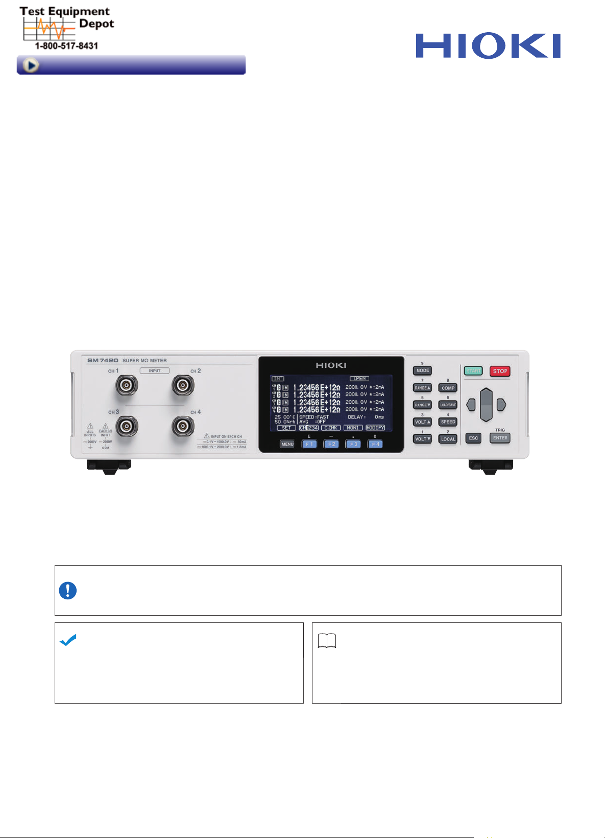
SM7420
Instruction Manual
SUPER MEGOHM METER
Be sure to read this manual before
using the instrument.
When using the instrument for the
rst time
Names and Functions of Parts
Preparing for Measurement
Nov. 2018 Revised edition 2
SM7420A961-02 18-11H
p.16
p.27
Safety information
Operating Precautions
Troubleshooting
Maintenance and Service
Error display and solution
p.7
p.8
p.133
p.136
EN

Contents
Introduction .................................................. 1
Notati
........................................................... 1
Verifying Package Contents
Measurement Procedure
Safety Information
Operating Precautions
....................................... 7
........................ 3
............................. 6
................................. 8
1 Overview 15
1.1 Product Overview and Features ....... 15
1.2
Names and Functions of Parts ......... 16
1.3
Screen Conguration and Operation 21
Measurement screens ................................21
Settings screens
1.4 Basic Key Operation ........................ 23
Displaying measurement screen ................23
Displaying the various menu settings
screens
Selecting settings items
Methods for changing numerical values
................................................
.........................................22
.......23
..............................24
.....25
2 Preparing for
Measurement
2.1 Connecting Power Cord to
Instrument
2.2
Connecting Measurement Leads
to Instrument
2.3
Connecting Electrode ....................... 28
Connecting Humidity Sensor ............ 29
2.4
2.5
Outputting Measurement Current
Value Converted to Analog Signal
2.6
Turning On/Off Instrument ................ 31
Inspection Before Use ...................... 32
2.7
........................................ 27
.................................... 28
27
.... 30
3 Basic Measurement 33
3.1 Setting Measured Value Display
Mode ................................................ 33
Changing display notation ..........................34
Changing displayed digits ...........................34
3.2 Setting Voltage Value for
Resistance Calculation ..................... 35
3.3 Setting Measurement Speed ............ 36
3.4 Changing Current Range ................. 37
3.5 Connecting Measurement Leads
or Electrode to Object to Be
Measured ......................................... 38
3.6 Starting/Stopping Measurement ....... 39
3.7 Conrming Measurement Results .... 39
Detecting a measurement abnormality .......39
Temperature measurement indication ........39
Out-of-range indication ...............................39
3.8 Basic Measurement Examples ......... 40
4 Applied Measurement 43
4.1 Starting Measurement After
Measured Value Becomes Stable
(Delay Function)
4.2
Reducing Variation in Measured
alues (Average Function) ............... 44
V
4.3
Changing Measurement Starting
Conditions (Trigger Function)
Setting the trigger mode .............................46
Inputting an external trigger
4.4 Maintaining Measurement
Accuracy (Self-Calibration Function)
4.5
Contact Check (Various Settings) .... 49
Canceling Capacitance of
4.6
Measurement Fixture
(Fixture Capacitance Open
Correction Function) ......................... 52
Contact Check (Executing Contact
4.7
Check, Setting Reference Value)
4.8
Setting Resistivity Calculation
(Resistivity Measurement Function)
4.9
Further Accelerating
(Function of Updating Drawing
During Measurement)
............................... 43
........... 46
........................46
47
..... 53
. 55
Measurement
...................... 58
5 Measurement Methods
Suitable for Various
Objects to Be Measured 59
5.1 Measuring Components of Circuits .. 59
Measurement with use of a
measurement xture ...................................60
Measurement without use of a
measurement xture ...................................61
Automatic measurement .............................62
5.2 Measuring Flat Sample .................... 63
Measurement using pin type terminals .......63
Measurement using an electrode for
measuring surface resistance .....................63
Measurement using an electrode for a
at sample ..................................................64
Volume resistance measurement and
surface resistivity measurement
(the functional role of the guard electrode) .64
5.3 Measuring a Liquid Sample .............. 66
When using an electrode for liquid
samples ......................................................66
5.4 Measurement With Use of
Shielding Box ................................... 67
1
2
3
4
5
SM7420A961-02
i

Contents
5.5 Measuring Current ........................... 68
6 Judging Measured
Value (Comparator
Function) 69
6.1 Setting Judgment Sound .................. 71
6.2
Conrming Judgment Results .......... 72
7 Saving and Loading
Settings (Panel Saving
and Loading) 73
7.1 Saving Settings
(Panel Saving Function)
Loading Settings
7.2
(Panel Loading Function)
Changing Panel Name ..................... 76
7.3
7.4
Deleting Panel Contents .................. 77
................... 74
................. 75
8 System Setting 79
8.1 Setting Sound of Key Operation ....... 79
8.2
Disabling Key Operation
(Key Lock Function)
8.3
Browsing, Deleting, and Outputting
Internal Memory Data
Browsing and deleting data ........................82
8.4 Setting D/A Output ........................... 83
8.5
Adjusting Screen Contrast ............... 84
Adjusting Backlight Brightness ......... 84
8.6
8.7
Changing Power Frequency
Setting
(Power Frequency Setting Function)
8.8 Initializing Settings (Reset) ............... 86
Default setting list .......................................87
8.9 Checking Instrument Information ..... 88
9
External Control (EXT I/O)
......................... 80
....................... 81
... 85
89
Output signal status on start-up ..................97
Flowchart for acquiring a judgment
result or a measured value with the
external trigger setting
9.4 Internal Circuit Conguration ............ 98
Electrical Specications ..............................99
Examples of connection
9.5 Assembling Male Connector for
EXT I/O (Accessory)....................... 102
9.6
EXT I/O T
Testing
9.7 Settings for External Input and
Output
Trigger logic ..............................................104
Trigger lter
GO-signal outputting logic level
EOM signal output mode
erminal Input and Output
..........................................
............................................ 104
...............................................105
................................97
............................100
.. 103
................106
..........................107
10 Communications
(USB, RS-232C, GP-IB)
10.1 Summary and Features of Interface 109
USB Interface ..................................110
10.2
Installing the USB driver ........................... 110
Connecting the USB cable ........................ 110
Setting the instrument
10.3 RS-232C Interface ..........................112
Connecting the RS-232C cable ................ 112
Setting the instrument ............................... 11 3
Setting the controller (Computer or PLC)
10.4 GP-IB Interface ...............................114
Connecting the GP-IB cable ..................... 114
Setting the instrument ............................... 11 4
10.5 Settings Common to Interfaces .......116
Outputting measured values (data
output function)
(RS-232C and USB only)
Displaying communication commands
(communication monitor function)
10.6 Control by Using Commands ..........118
Remote state ............................................ 118
Local state ................................................ 118
............................... 111
.......................... 11
109
. 113
............. 117
6
9.1 Switching Current Sink (NPN) /
Current Source (PNP) ...................... 90
9.2 External Input/Output Terminals
and Signals
Instrument-side connector and mating
connectors ..................................................90
Instrument-side connector pin assignment .91
Functions of each of the signals .................93
9.3 Timing Chart ..................................... 94
From when measurement starts to
when judgment result is acquired ...............94
...................................... 90
ii
11 Specications 119
11.1 General Specications ....................119
11.2 Input/Output/Measurement
Specications ................................. 120
Basic specications ..................................120
Accuracy specications ............................121
11.3 Function specications ................... 124
11.4 Interface Specications .................. 130
11.5 External I/O Specications ............. 131

Contents
12 Maintenance and
Service 133
12.1 Troubleshooting .............................. 133
Q&A (Frequently Asked Questions) ..........133
Error display and solution
12.2 Inspection, Repair and Cleaning .... 138
Appendix Appx.1
Appx. 1 Internal Circuits ................... Appx.1
Appx. 2
Appx. 3
Appx. 4
App
Appx. 6 Modifying Measurement
Appx. 7
Appx. 8
Changes in Current
Running through Insulator
Countermeasures Against
................................... Appx.3
Noise
Using Instrument with
2000 V or Higher Voltage
Applied (With External
Power Supply) .................... Appx.6
x. 5
Assembling Switching
for Object to Be Measured
Connecting objects to be measured and
the switching unit to the instrument .....Appx.7
Selecting relays to be installed in the
switching unit
Circuit diagram of the switching unit ....Appx.9
Including current-limiting resistor
(protective resistance) and relay ..........Appx.9
Current-limiting resistor ......................Appx.10
Lead
Mounting Instrument in
Rack
Dimensional Diagram ....... Appx.15
.......................................Appx.8
.................................. Appx.11
.................................. Appx.13
.........................136
.. Appx.2
Unit
.. Appx.7
11
12
3
4
5
6
7
8
Index Ind.1
9
10
Appx. Ind.
iii

Contents
iv
Introduction
Thank you for purchasing the Hioki SM7420 Super Megohm Meter. To obtain maximum
performance from the instrument, please read this manual rst, and keep it handy for future
reference.
Target audience
This manual has been written for use by individuals who use the product in question or who teach
others to do so. It is assumed that the reader possesses basic electrical knowledge (equivalent to
that of someone who graduated from the electrical program at a technical high school).
Trademark
• Adobe and Adobe Reader are trademarks of Adobe Systems Incorporated.
• Microsoft and Windows are either registered trademarks or trademarks of Microsoft Corporation
in the United States and other countries.
• TEFLON is a registered trademark or a trademark of The Chemours Company FC, LLC.
Introduction
Notati
Concerning Safety
In this manual, the risk seriousness and the hazard levels are classied as follows.
Indicates an imminently hazardous situation that will result in death or serious injury
DANGER
WARNING
CAUTION
IMPORTANT
to the operator.
Indicates a potentially hazardous situation that may result in death or serious injury
to the operator.
Indicates a potentially hazardous situation that may result in minor or moderate
injury to the operator or damage to the instrument or malfunction.
Indicates information related to the operation of the instrument or maintenance tasks
with which the operators must be fully familiar.
Indicates a high voltage hazard.
If a particular safety check is not performed or the instrument is mishandled, this
may give rise to a hazardous situation; the operator may receive an electric shock,
may get burnt or may even be fatally injured.
Indicates prohibited actions.
Indicates the action which must be performed.
1
Notati
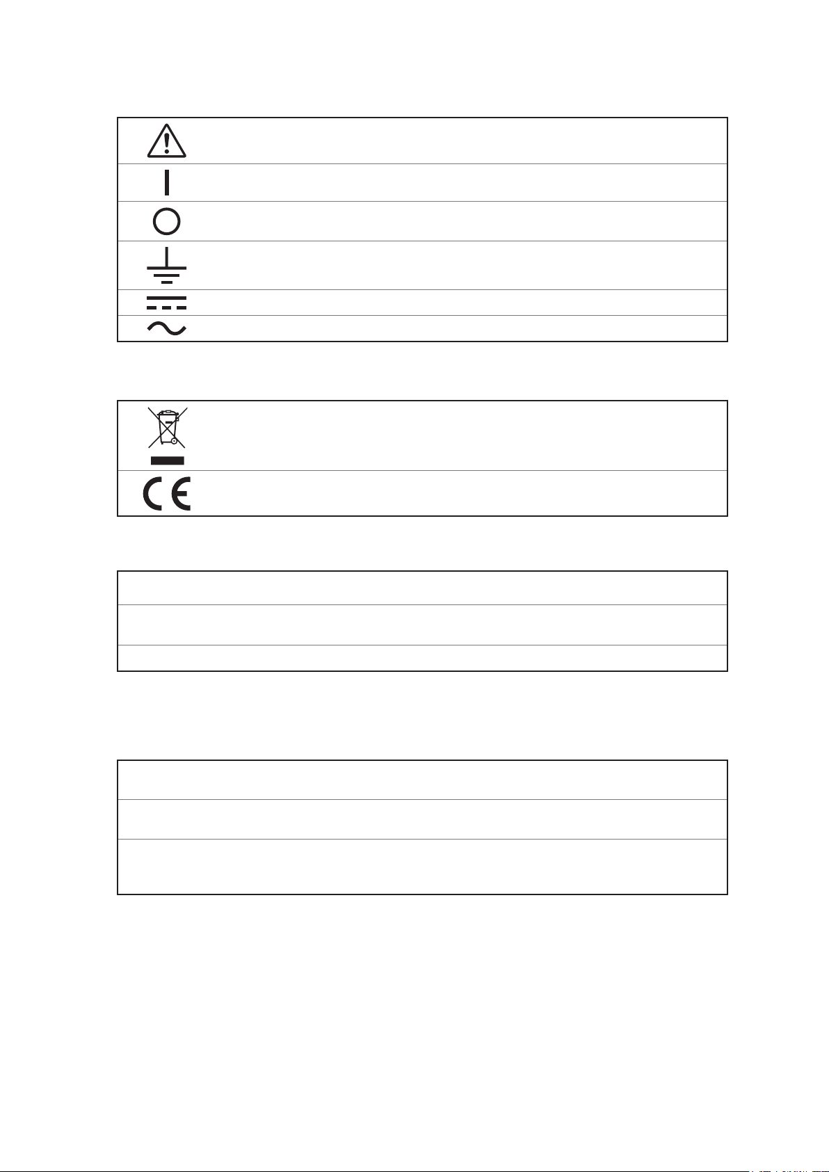
Symbols on the instrument
Indicates cautions and hazards. When the symbol is printed on the instrument, refer to a
corresponding topic in the Instruction Manual.
Indicates the ON side of the power switch.
Indicates the OFF side of the power switch.
Indicates a grounding terminal.
Indicates DC (Direct Current).
Indicates AC (Alternating Current).
Symbols for various standards
Indicates the Waste Electrical and Electronic Equipment Directive (WEEE Directive) in EU
member states.
Indicates that the product conforms to regulations set out by the EU Directive.
Others
*
SET
(Bold character)
[ ]
Additional information is presented below.
Operation keys are displayed in bold.
Names on the screen are indicated with brackets [ ].
Accuracy
We dene measurement tolerances in terms of f.s. (full scale), rdg. (reading), and dgt. (digit) values
with the following meanings:
f.s.
rdg.
dgt.
(maximum display value or scale range)
The currently selected range.
(reading or displayed value)
The value currently being measured and indicated on the measuring instrument.
(resolution)
The smallest displayable unit on a digital measuring instrument, i.e., the input value that
causes the digital display to show a “1” as the least-signicant digit.
2
Verifying Package Contents
Verifying Package Contents
When you receive the instrument, inspect it carefully to ensure that no damage occurred during
shipping. In particular, check the accessories, panel switches, keys, and connectors. If damage
is evident, or if it fails to operate according to the specications, contact your authorized Hioki
distributor or reseller.
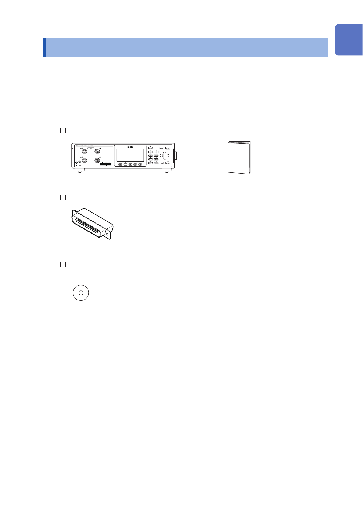
Main unit and accessories
Conrm that these contents are provided.
Model SM7420 Super Megohm Meter Instruction Manual
Male connector for EXT I/O Power cord
CD (Communications Command Instruction Manual,
USB driver)*
* The latest version can be downloaded from our
website.
3
Verifying Package Contents
Options
The following options are available for the instrument. Contact your authorized Hioki distributor or
reseller when ordering.
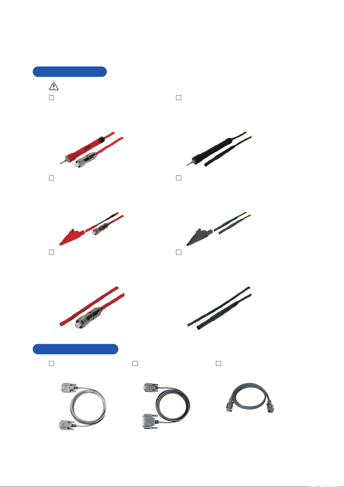
Measurement leads
See p. 10.
Model L2230 Pin Type Lead (Red) Model L2231 Pin Type Lead (Black)
Length: 1 m Length: 1 m
Terminal shape: Triaxial BNC Terminal shape: Banana
Maximum rated voltage: 2000 V Maximum rated voltage: 2000 V
Maximum rated current: 1 A Maximum rated current: 1 A
Model L2232 Clip Type Lead (Red) Model L2233 Clip Type Lead (Black)
Length: 1 m Length: 1 m
Terminal shape: Triaxial BNC Terminal shape: Banana
Maximum rated voltage: 2000 V Maximum rated voltage: 2000 V
Maximum rated current: 1 A Maximum rated current: 1 A
Model L2234 Open Lead (Red) Model L2235 Open Lead (Black)
Length: 3 m Length: 3 m
Terminal shape: Triaxial BNC Terminal shape: Banana
Maximum rated voltage: 2000 V Maximum rated voltage: 2000 V
Maximum rated current: 1 A Maximum rated current: 1 A
Communication cables
Model 9637 RS-232C Cable
(9pin-9pin/1.8 m)
Model 9638 RS-232C Cable
(9pin-25pin/1.8 m)
Model 9151-02 GP-IB
Connector Cable
(2 m)
4
Verifying Package Contents
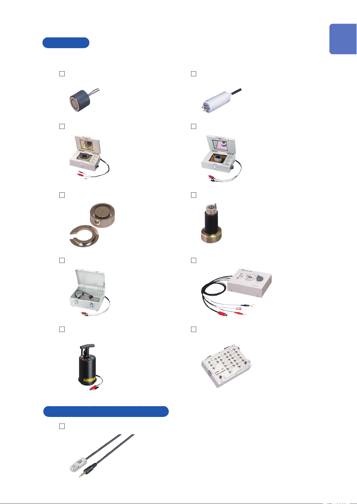
Electrodes
Conversion of the connectors is required to connect these electrodes. Contact your authorized
Hioki distributor or reseller.
Model SME-8301 Surface Resistance
Measurement Electrode
Model SME-8310 Plate Sample Electrode SME-8311 Electrode for Flat Sample
Model SME-8320 Weight Electrode Model SME-8330 Liquid Sample Electrode
Model SME-8302 Electrode for Surface
Resistance
Model SME-8350 Shielding Box Model SME-8360 Electrode for Chip Capacitor
Model SM9001 Surface/Volume Resistance
Measurement Electrode
Temperature and humidity sensor
Model Z2011 Humidity Sensor
Model SR-2 Standard Resistor
5
Measurement Procedure
Measurement Procedure
Be sure to read “Operating Precautions” (p. 8) beforehand.
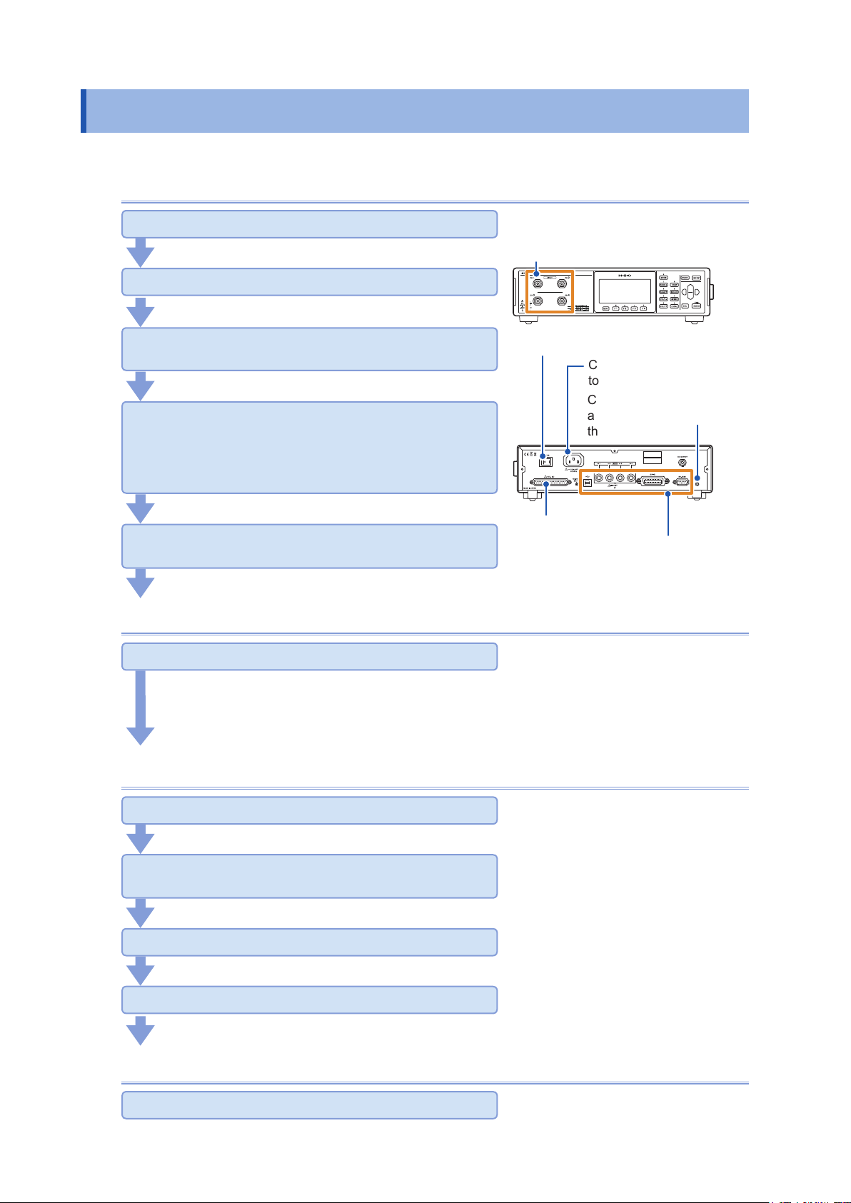
Installing, connecting, and turning on the instrument
Install the instrument. (p. 9)
Connect the power cord to the instrument. (p. 27)
Connect the measurement lead, electrode, and the
Humidity Sensor to the instrument. (p. 28)
Connect other devices to the instrument via the
external interface (as needed).
• Use the EXT I/O. (p. 90)
• Connect a computer to the instrument for communications
through USB, RS-232C, or GP-IB. (p.
Turn on the instrument. (p. 31)
(It takes at least 30 minutes to complete a warm-up.)
109)
Setting the instrument (p. 33)
Connect the measurement lead
and electrode to the instrument.
Turn on the instrument.
Connect the power cord
to the instrument.
Connect the temperature
and humidity sensor to
the instrument.
Use the EXT I/O.
Communicate with the computer
through USB, RS-232C, or GP-IB.
Set the measurement conditions (as needed).
• Basic setting (p. 33)
• Customized setting for measurement conditions (p. 43)
• Setting related to the system (p. 79)
• Default setting table (p. 87)
Starting the measurement
Execute the open correction. (p. 52)
If contact check is set to ON, execute the open correction.
Connect the measurement lead to an object to be
measured. (p. 38)
Start the measurement. (p. 39)
Check the measured values. (p. 39)
Press the STOP key to end the measurement. (p. 39)
If the trigger source setting is set to [EXTERNAL], the measurement automatically stops on completion
of each measurement.
Ending
Turn off the instrument. (p. 31)
6
Safety Information
Safety Information
This instrument is designed to conform to IEC61010 Safety Standards, and has been thoroughly
tested for safety prior to shipment. However, using the instrument in a way not described in this
manual may negate the provided safety features.
Before using the instrument, be certain to carefully read the following safety notes:
DANGER
Mishandling during use could result in injury or death, as well as damage to the
instrument. Be certain that you understand the instructions and precautions in
the manual before use.
WARNING
With regard to the electricity supply, there are risks of electric shock, heat
generation, re, and arc ash due to short circuits. If persons unfamiliar with
electricity measuring instrument are to use the instrument, another person
familiar with such instruments must supervise operations.
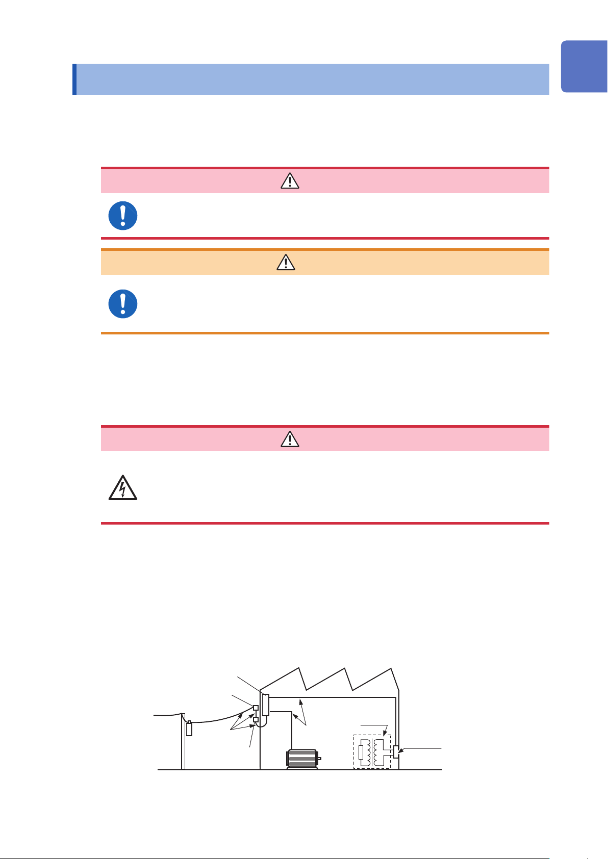
Measurement categories
To ensure safe operation of measuring instruments, IEC61010 establishes safety standards
for various electrical environments, categorized as CAT II to CAT IV, and called measurement
categories.
DANGER
• Using a measuring instrument in an environment designated with a higher-
numbered category than that for which the instrument is rated could result in a
severe accident, and must be carefully avoided.
• Never use a measuring instrument that lacks category labeling in a CAT II to
CAT IV measurement environment. Doing so could result in a serious accident.
CAT II: When directly measuring the electrical outlet receptacles of the primary electrical
circuits in equipment connected to an AC electrical outlet by a power cord (portable
tools, household appliances, etc.)
CAT III: When measuring the primary electrical circuits of heavy equipment (xed installations)
connected directly to the distribution panel, and feeders from the distribution panel to
outlets
CAT IV:
When measuring the circuit from the service drop to the service entrance, and to the
power meter and primary overcurrent protection device (distribution panel)
Distribution Panel
Service Entrance
Service Drop
CAT IV
Power Meter
Internal Wiring
CAT III
Fixed Installation
CAT II
T
Outlet
7
Operating Precautions
Operating Precautions
Follow these precautions to ensure safe operation and to obtain the full benets of the various
functions.
DANGER
If the measurement lead or the instrument is damaged, there is a risk of electric
shock. Before using the instrument, perform the following inspection:
• Before using the instrument check that the coating of the measurement leads
are neither ripped nor torn and that no metal parts are exposed. Using the
instrument under such conditions could result in electric shock. Replace the
measurement leads with those specied by our company.
• Verify that the instrument operates normally to ensure that no damage occurred
during storage or shipping. If you nd any damage, contact your authorized
Hioki distributor or reseller.
To prevent an electric shock, conrm that the braided conductor for shielding
wire is not exposed. If a braided conductor for shielding wire is exposed, do not
use the cable.
Instrument installation
Installing the instrument in inappropriate locations may cause a malfunction of
instrument or may give rise to an accident. Avoid the following locations:
• Exposed to direct sunlight or high temperature
• Exposed to corrosive or combustible gases
• Exposed to a strong electromagnetic eld or electrostatic charge
• Near induction heating systems (such as high-frequency induction heating
systems and IH cooking equipment)
• Susceptible to vibration
• Exposed to water, oil, chemicals, or solvents
• Exposed to high humidity or condensation
• Exposed to high quantities of dust particles
• Do not place the instrument on an unstable table or an inclined place. Dropping or
knocking down the instrument can cause injury or damage to the instrument.
• This instrument is not drip-proof. Water droplets on the connector may result in
malfunctions.
WARNING
CAUTION
8
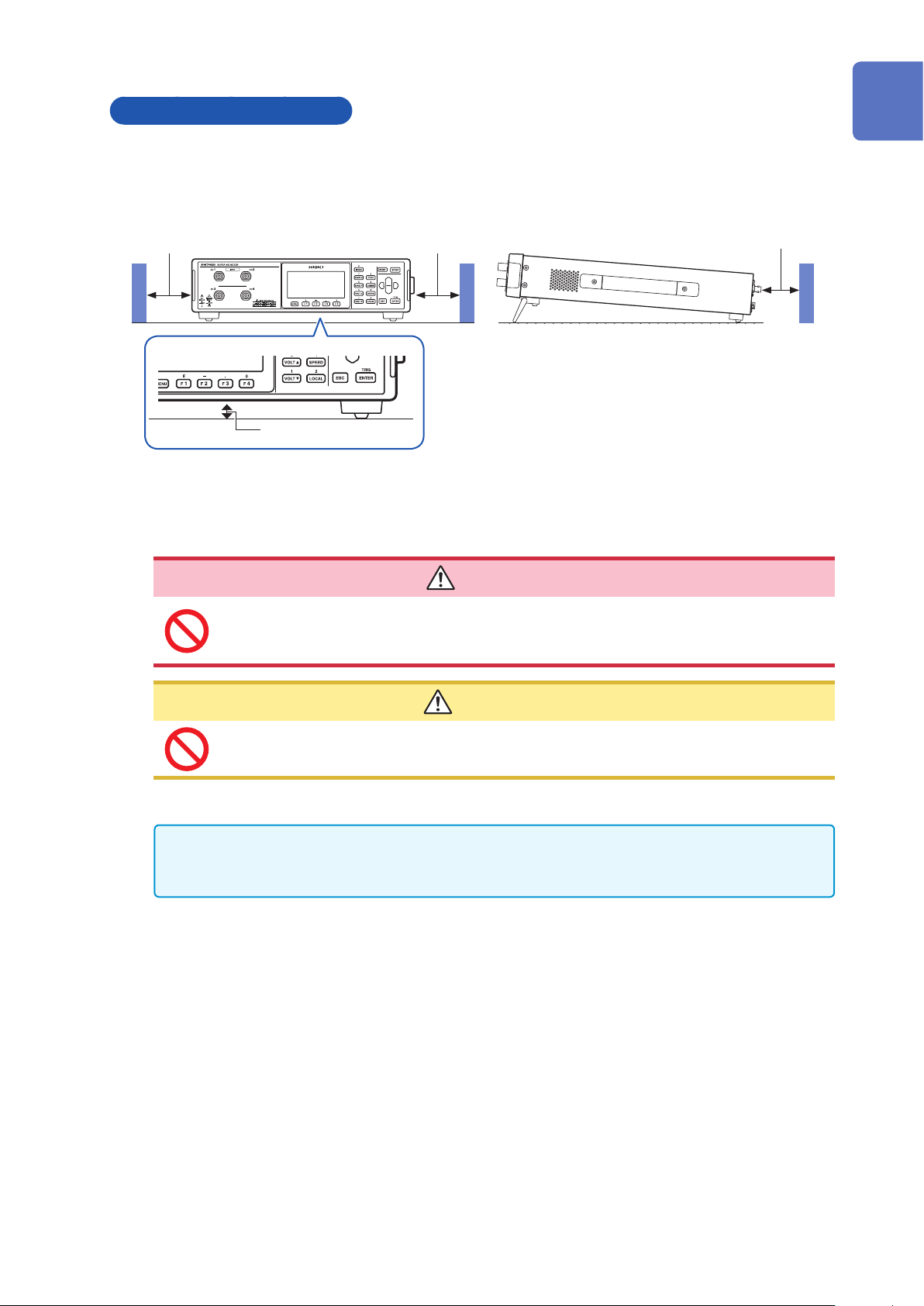
Installing the instrument
To prevent overheating, be sure to leave the specied clearances around the instrument.
• Install with the bottom surface facing downward.
• Vents must not be obstructed.
50 mm or more50 mm or more
15 mm or more
“Unfolding and retracting the stands” (p. 18)
Operating Precautions
10 mm or more
Rear
Handling the instrument
To avoid electric shock, do not remove the instrument’s case. The internal
components of the instrument carry high voltages and may become very hot
during operation.
To avoid damage to the instrument, protect it from physical shock when transporting
and handling. Be especially careful to avoid physical shock from dropping.
This instrument may cause interference if used in residential areas. Such use must be avoided
unless the user takes special measures to reduce electromagnetic emissions to prevent
interference to the reception of radio and television broadcasts.
DANGER
CAUTION
9
Operating Precautions
Before connecting the power cord to the instrument
DANGER
Use only the designated power cord with this instrument. Use of other power
cords may cause re.
WARNING
• Before turning the instrument on, make sure the supply voltage matches that
indicated on its power connector. Connection to an improper supply voltage
may damage the instrument and present an electrical hazard.
• To avoid electrical accidents and to maintain the safety specications of this
instrument, connect the power cord provided only to an outlet.
CAUTION
• Do not connect the supply voltage improperly. Doing so may damage the instrument’s
internal circuitry.
• To avoid damaging the cords, unplug it by grasping the connector, not the cord.
Before connecting the measurement leads and electrode to the instrument
WARNING
• Do not use the instrument with circuits that exceed its ratings or specications.
Doing so may damage the instrument or cause it to become hot, resulting in
electric shock.
• The maximum rated to-ground voltage of the input terminal is 2000 V DC. Do
not apply any higher voltage input to the input terminal.
• Use only the specied measurement lead. If using a measurement lead other
than the one specied, you cannot perform measurement safely.
• To avoid electric shock, do not exceed the lower of the ratings shown on the
instrument and measurement leads.
Before connecting the Humidity Sensor to the instrument
CAUTION
• The sensor used in the Humidity Sensor is a thin, precision platinum lm. Be aware
that excessive voltage pulses or static discharges can destroy the lm.
• Avoid subjecting the tip of the Humidity Sensor to physical shock, and avoid sharp
bends in the leads. These may damage the probe or break a wire.
• Note that the ambient temperature does not exceed the temperature range specied
in “Specications of Model Z2011 Humidity Sensor” (p. 123).
10
Before performing a measurement
• While measuring insulation resistance, dangerous voltage is applied to the
measurement terminals. To avoid electric shock, do not touch the tip of the
measurement leads.
• Even after the STOP key is pressed, the measurement voltage may remain in
the measured object. Because there is a risk of an electric shock, take care
to not touch metallic parts to which the voltage is applied until they are fully
discharged.
To avoid malfunctions of the instrument, insert an adequate protective resistor between
the external power supply and the object to be measured. A short-circuit of the terminals
of the object causes the instrument to be subject to a voltage output from the external
power supply.
• To avoid malfunctions of the instrument, limit the input current at up to 1.8 mA during
the testing using a measurement voltage of between 1000 V and 2000 V.
Operating Precautions
WARNING
CAUTION
See “Appx. 4 Using Instrument with 2000 V or Higher Voltage Applied (With External Power
Supply)” (p.
Appx.6).
Before performing an automatic measurement
CAUTION
To protect the relay contacts, switching the measurement terminals with relays leaving
a measurement voltage output requires a protective resistor* inserted in series in the
circuit.
Protective resistance value ≥ (Measurement voltage) / (Maximum allowable current)
* Implements resistance to prevent the current owing through the contact from
exceeding the maximum allowable current of the contact
Before using the shielding box
WARNING
Be sure to connect the external case of the shielding box to the ground.
In addition, take sufcient precautions to avoid an electric shock.
Before removing the measured object
If a high-voltage is used to measure resistance, because measurement voltage
may remain in the measured object even after the measurement has ended,
there is the risk of an electric shock if you try to immediately remove the object.
Remove the measured object after the dangerous voltage has been discharged.
WARNING
11
Operating Precautions
Before controlling the instrument externally
WARNING
To avoid electric shock or damage to the equipment, always observe the following
precautions when connecting to connectors:
• Be careful to avoid exceeding the ratings of connectors.
• During operation, a wire becoming dislocated and contacting another
conductive object can be serious hazard. Use screws to secure the RS-232C
connector, GP-IB connector, and EXT I/O terminal.
• Ensure that devices and systems to be connected to the RS-232C connector,
GP-IB connector, or EXT I/O terminal are properly isolated.
CAUTION
You must not operate the EXT I/O MODE switch (NPN/PNP) while the instrument is
turned on.
Select the external I/O mode between NPN and PNP based on devices that are
externally connected (p. 90).
Before connecting the communication cable to the instrument
DANGER
To avoid electrical hazards and damage to the instrument, do not apply voltage
exceeding the rated maximum to the EXT I/O terminal.
CAUTION
• Use a common ground for both the instrument and the computer. Use of different
ground circuits will result in a potential difference between the instrument’s ground
and the computer’s ground. If the communications cable is connected while such a
potential difference exists, it may result in equipment malfunction or failure.
• Before connecting any communications cable to the instrument or disconnecting any
communications cable from the instrument, always turn off the instrument and the
computer. Failure to do so could result in equipment malfunction or damage.
• After connecting the communications cable, tighten the screws on the connector
securely. Failure to secure the connector could result in equipment malfunction or
damage.
Before performing the open correction
12
WARNING
If an open correction is carried out, a measurement voltage is instantly output
from the measurement terminal.
Before carrying out an open correction (pressing the F2 key [EXEC]), check that
no human body is in contact with any jigs or measurement circuits.

Operating Precautions
Precautions during shipment
Store the packaging in which the instrument was delivered, as you will need it when transporting
the instrument.
CD precautions
• Exercise care to keep the recorded side of discs free of dirt and scratches. When writing text
on a disc’s label, use a pen or marker with a soft tip.
• Keep discs inside a protective case and do not expose to direct sunlight, high temperature, or
high humidity.
• Hioki is not liable for any issues your computer system experiences in the course of using this
disc.
13

Operating Precautions
14

1
Overview
1.1 Product Overview and Features
This instrument is an insulation resistance meter containing a highly sensitive ammeter.
Employing the triaxial BNC connector enables the instrument to measure high resistance such as
resistance of insulators with no inuence of exogenous noise. The maximum measurement voltage
is 2000 V.
Stable measurements for a variety of items
• The triaxial BNC connector is used to have external noise resistant structures.
• The maximum measurement voltage is 2000 V, so various objects can be simply measured with
a single instrument.
• The instrument has a wide measuring range. (Depends on applied voltage)
• Resistance measuring range: 50 Ω to 2 ×10¹⁹ Ω; Current measuring range: 0.1 fA to 2 mA
• Because temperature and humidity can be measured simultaneously, change in resistance can
be checked with the change in temperature and humidity.
• The contact check function enables you to perform stable measurements.
Suitable for production lines
• High-speed measurement; it takes only 6.4 ms from input of a trigger to output of the INDEX
signal.
• The frequency change function of contact check reduces interference with other devices in the
production line.
• It is not necessary to correct cable length even when changing production line construction
because the instrument automatically corrects the cable length of contact check.
• Because you can check the control status with the command monitor function and the external
I/O monitor function, you can quickly construct a production line.
• Because the external I/O is compatible with both NPN and PNP types, you can immediately use it
on your production line.
1
Overview
What can be measured
• Insulation resistance between capacitor terminals
• Insulation resistance between a battery terminal and a case
• Insulation resistance between coils of common mode lters
• Checking breakdown voltage
• Surface resistivity and volume resistivity of lm, etc.
• Insulation resistance of liquid sample
15
Names and Functions of Parts
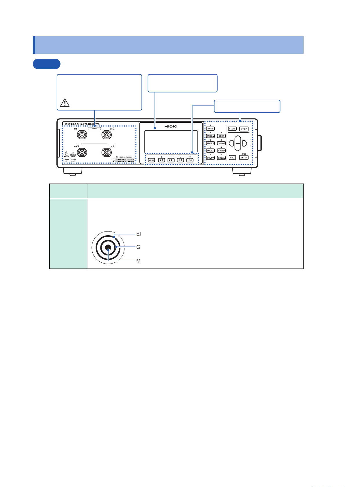
1.2 Names and Functions of Parts
Front
Measurement terminals (INPUT)
Connect measurement leads to
these terminals.
See p. 10.
Measurement
terminals
These are measurement input terminals.
Have triaxial structure. The central conductor is for measurement input. The outermost
electrode is connected to the GROUND potential of the measurement circuit. The secondoutermost electrode is connected to the ground (case metal part).
INPUT
Screen
Monochrome graphic LCD
Description
Electromagnetic shielding wire
Guard wire for measurement
Measurement input wire
Operation keys (p. 19)
Additionally installing the shield wires
in the measurement line enables
the instrument to perform stable
measurement with no inuence of
exogenous noise.
16
Names and Functions of Parts
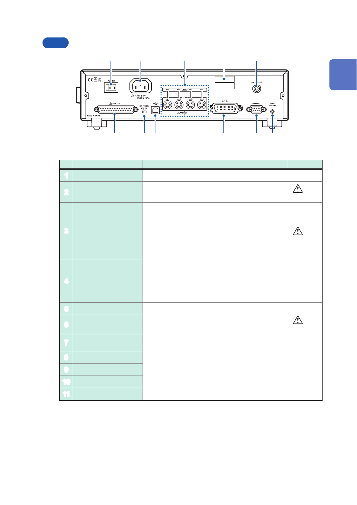
Rear
1 2 3 4 5
6 7 8 9 10 11
No. Name Description Reference
Power switch Turn on and off the instrument, ipping this switch. p. 31
1
1
Overview
Power inlet Connects the accessory power cord to this inlet.
2
These terminals are used to share the GROUND potential
of the measurement circuit of the instrument and the
external power supply.
COM terminals
3
Serial number
4
D/A OUTPUT terminal Outputs a voltage proportional to the measured value. p. 30
5
EXT I/O terminal Connects an external controller to this connector.
6
EXT I/O MODE
7
switch
USB connector
8
Connect these terminals to the COM or the GND terminal
of the external power supply.
If the GND terminal of the external power supply is shared
by 4 channels, connect the COM1 terminal of instrument
to the GND terminal of the external power supply.
Indicates the serial number.
The serial number consists of 9 digits. The rst two (from
the left) indicate the year of manufacture, and the next two
indicate the month of manufacture.
Do not remove this label because it is required for product
support.
Left: Current sink (NPN), Right: Current source (PNP) p.
p. 10
27
p.
p. 10
–
p. 12
p. 89
90
GP-IB connector
9
RS-232C connector
10
TEMP. SENSOR terminal Connects Model Z2011 Humidity Sensor to this terminal. p. 29
11
Connects a computer to one of these connectors. p. 109
17
Names and Functions of Parts
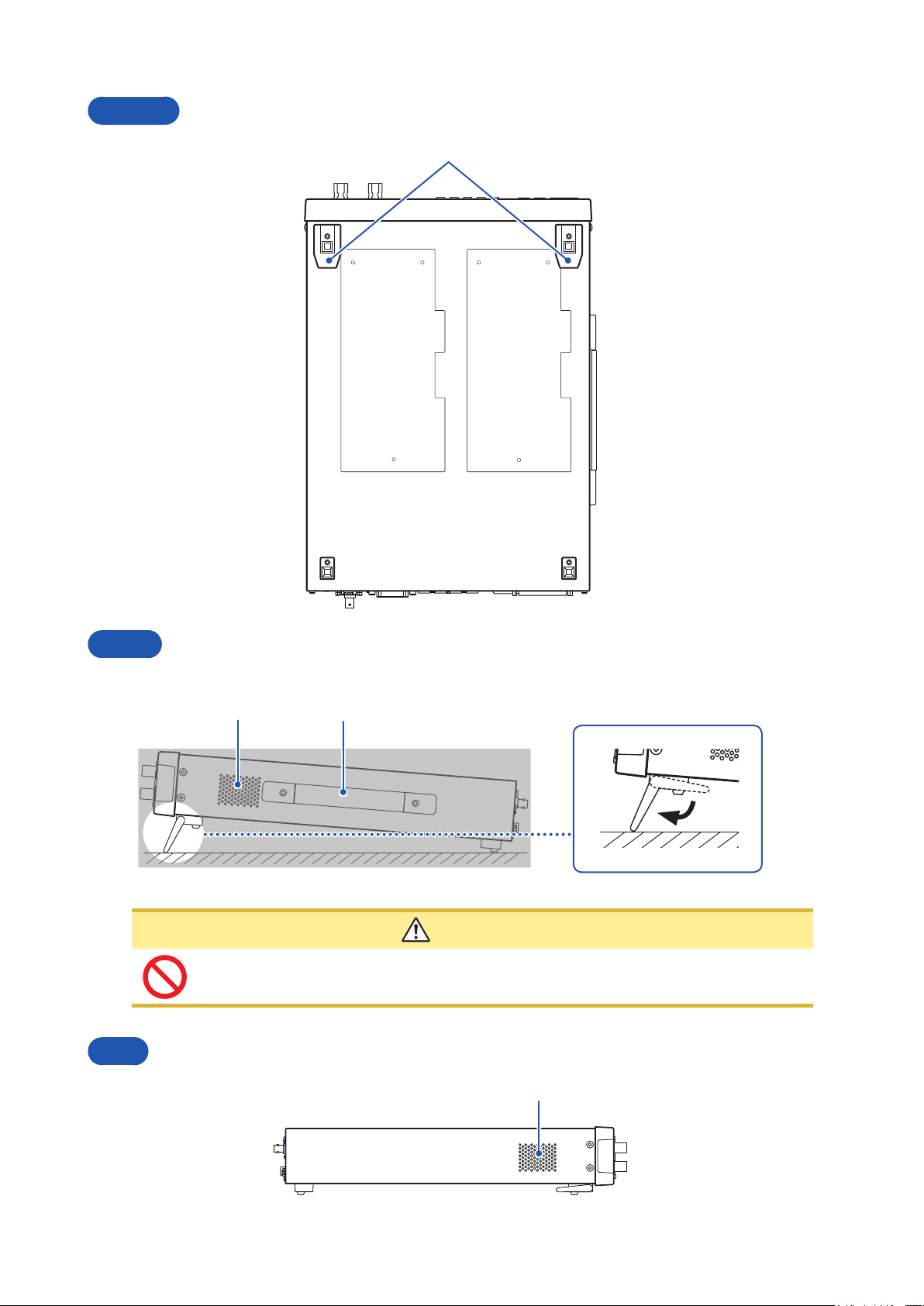
Bottom
Stands
Right
Unfolding and retracting the stands
Vent Handle
Do not apply heavy downward pressure with the stand extended. The stand could be
damaged.
Left
CAUTION
Vent
18
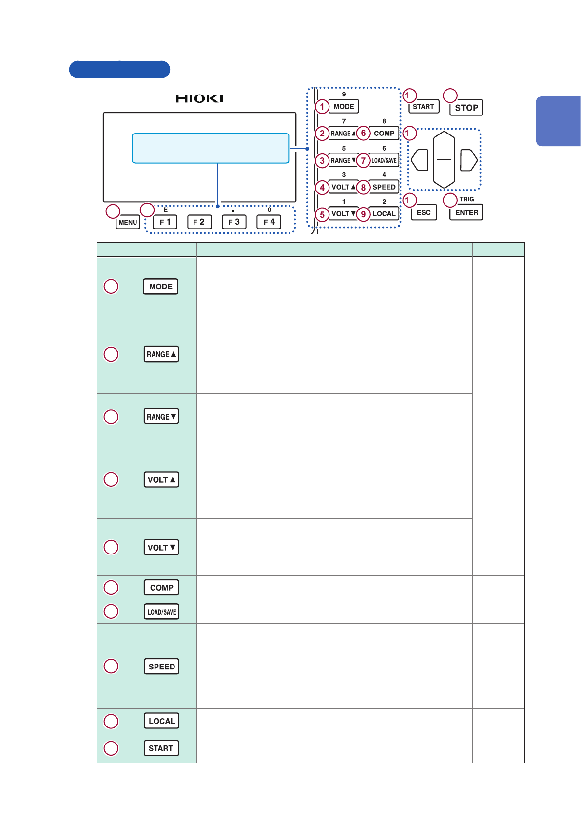
Operation keys
Names and Functions of Parts
10 11
1
These keys also serve as the numeric
keypad to enter the numerical values.
15
No. Key Description Reference
1
2
3
4
5
16
Switches the measurement mode.
The mode changes every time the key is pressed in the following
order:
Resistance, Current, Surface resistance, Volume resistance, Liquid
volume resistance, and returns back to Resistance.
Switches the present current range to the next upper one. You can
change settings on the measurement screen.
The mode changes every time the key is pressed in the following
order:
20 p, 200 p, 2 n, 20 n, 200 n, 2 u, 20 u, 200 u, and 2 m.
Some ranges are not available depending on the measurement
speed setting.
Switches the present current range to the next lower one. You can
change settings on the measurement screen.
The range changes every time the key is pressed in the reverse
order of the above.
Switches the present voltage value for resistance calculation to
the next upper one. You can change settings on the measurement
screen.
The value changes every time the key is pressed in the following
order:
0.1, 0.5, 1, 2.5, 5, 10, 25, 50, 100, 250, 500, 1000, 1500, 2000, 2500,
3000, 3500, 4000, 4500, and 5000
Switches the present voltage value for resistance calculation to
the next upper one. You can change settings on the measurement
screen.
The value changes every time the key is pressed in the reverse
order of the above.
2
3
4
5
6
7
8
9
12
13 14
33
p.
p.
37
p.
35
1
Overview
10
6
7
8
Displays the comparator settings screen. p. 69
Displays the panel load / panel save screen. p. 73
Switches the measurement speed. You can change settings on the
measurement screen.
The speed changes every time the key is pressed in the following
order:
FAST, FAST2, MED, SLOW, SLOW2, and returns back to FAST.
p. 36
Some measurement speeds are not available depending on
the current range setting.
9
Disables the remote control (communicating with an external device)
and enables the key operation.
Starts measurement. –
p. 118
19
Names and Functions of Parts
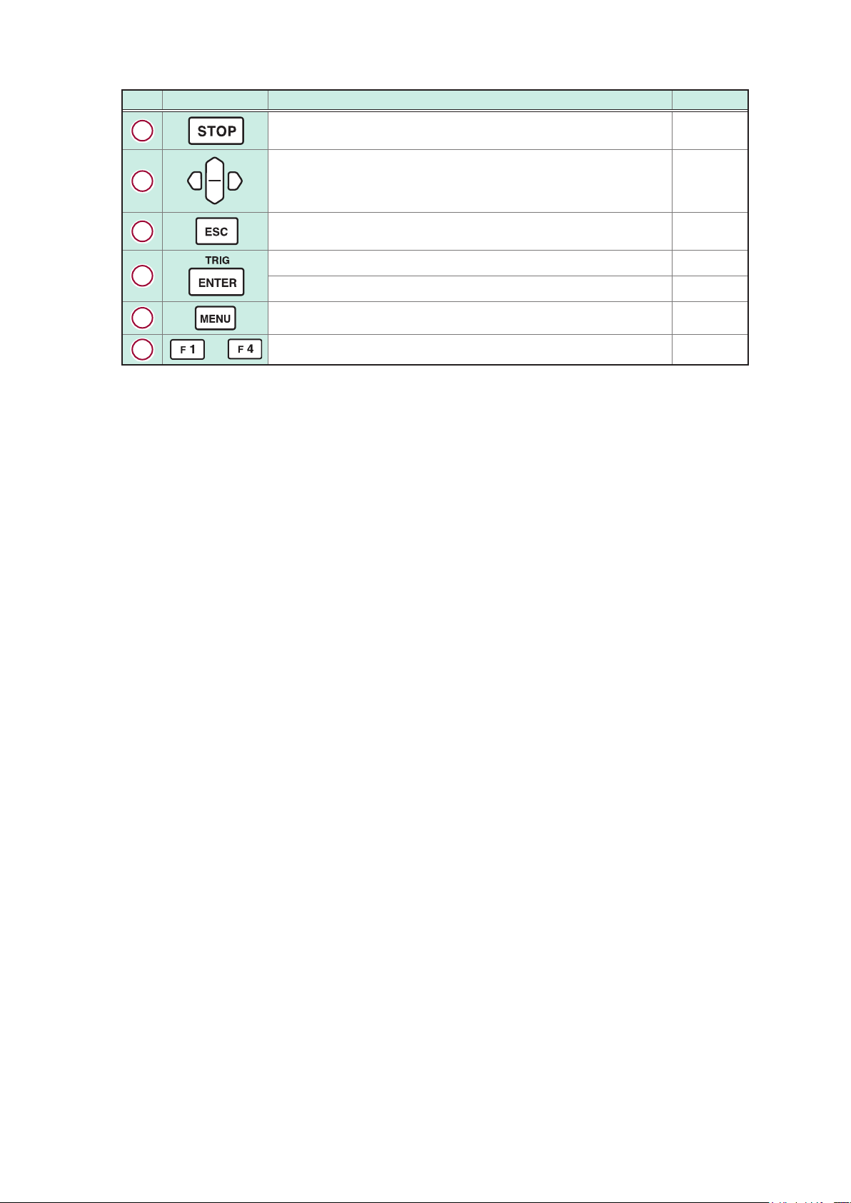
No. Key Description Reference
11
12
13
14
15
16
to
Stops measurement. –
• Moves the cursor to another setting item or digit.
• Changes numerical values.
• Cancels the setting.
• Returns to the measurement screen from other screens.
Conrms the setting. –
Inputs the trigger if the external trigger setting is used. p.
Moves the screen to another menu settings screen. p. 21
Function keys. Selects item on each settings screen. –
25
p.
–
46
20
Screen Conguration and Operation
1.3 Screen Conguration and Operation
The screens of the instrument consists of the measurement screens and the settings screens.
For information about the settings screen, see “Displaying the various menu settings screens”
(p. 23).
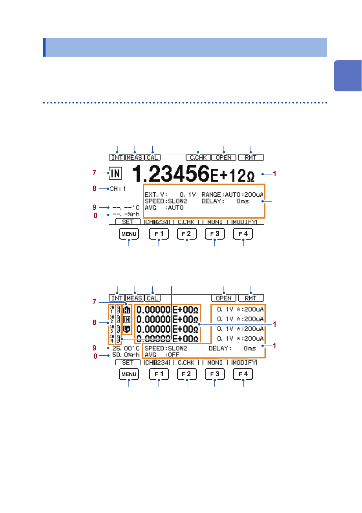
Measurement screens
Press the F3 key [MONI] to switch between the 1-channel display and the 4-channel display.
1-channel display
1
Overview
7
8
9
10
4-channel display
7
1 2 3 4 6
13 1514 16 17
1 2 3 4 6
5
5
11
12
8
9
10
11
12
13 1514 16 17
21
Screen Conguration and Operation
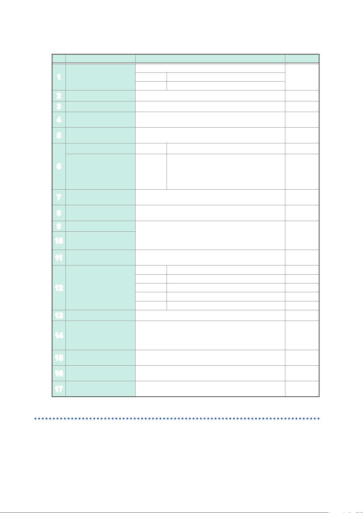
Displayed items
No. Content Description Reference
Trigger setting
1
Sampling data Appears during the sampling data. –
2
Self-calibration Appears during the self-calibration. p. 47
3
Contact check
4
Open correction
5
execution result
Key lock [K.LOCK] Appears while the key lock function is activated. p. 80
6
Remote [RMT]
Measurement judgments
7
Channel numbers
8
Temperature
9
Humidity
10
Measured values
11
Measurement conditions
12
MENU key [SET] Pressing the MENU key displays the menu settings display. p. 24
13
F1 key [CH1234]
14
F2 key [C.CHK]
15
F3 key [MONI]
16
F4 key [MODIFY]
17
Displays the presently set trigger.
p. 46[INT] Internal trigger
[EXT] External trigger
Appears when the contact check function is enabled.
Highlighted in reverse video if a contact error occures.
Displays the result when the open correction is executed
once.
Appears while the instrument is placed in the
remote status (communicating with an external
device).
Pressing the LOCAL key disables the remote
control.
Displays the judgment results if the measurement judgment
function is enabled.
Displays the presently selected channel number when using
the 1-channel display.
Displays temperature and humidity if the Humidity Sensor is
connected.
Displays an error message if the Humidity Sensor is not
connected to the instrument.
Displays the measured values corresponding to the
measured value display mode.
[EXT.V] Voltage value for resistance calculation p. 35
[SPEED] Measurement speed p.
[RANGE] Current range p.
[DELAY] Delay function p.
[AVG] A
The presently selected channel number is highlighted in
reverse video.
The channel is switched in the order from CH1 through CH4
every time the F1 key is pressed.
Pressing the F2 key executes the contact check (only with
the contact check set to [ON]).
Pressing F3 key switches between the 1-channel display
and the 4-channel display.
Pressing the F4 key enables the measurement conditions to
be changed.
verage function p. 44
p. 53
p.
p.
118
p. 69
p. 29
p.
137
p. 33
p. 53
52
–
36
37
43
–
–
–
Settings screens
For information about the settings display, see “Displaying the various menu settings screens”
(p. 23).
22
1.4 Basic Key Operation
Displaying measurement screen
Basic Key Operation
1
Overview
You can also press the ESC key to return to the measurement screen.
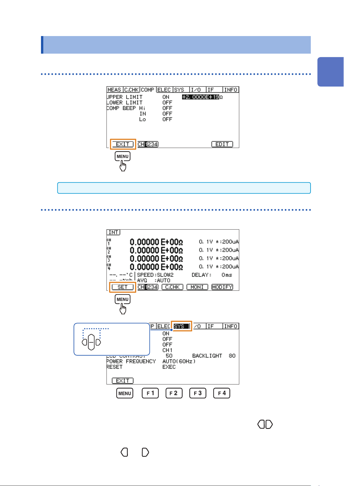
Displaying the various menu settings screens
This section shows an example of switching the measurement screen to the [SYS] screen.
1
2
Select
Select
(left or right)
(left or right)
In this manual, the procedure to display the settings screen is described as follows:
Procedure to display the settings screen: (Measurement screen) MENU key >
(That is to say, to display the settings screen, on the measurement screen, press the MENU key,
and then press the keys
and to select the [SYS] tab.)
[SYS] tab
23
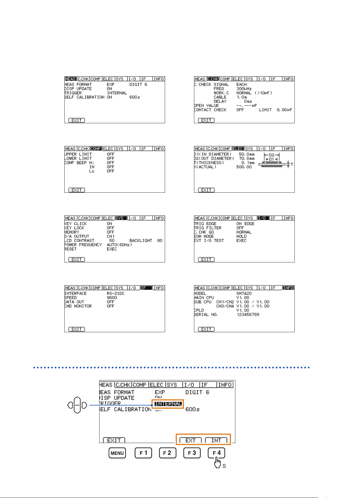
Basic Key Operation
List of menu settings screens
[MEAS] screen
Conguring settings for measurement
[COMP] screen
Conguring settings for measured value judgment
[SYS] screen
Conguring system settings
[C.CHK] screen
Conguring settings for open correction and contact
check
[ELEC] screen
Conguring settings for calculating resistivity
[I/O] screen
Conguring settings for external control
[IF] screen
Conguring settings for interface.
Selecting settings items
Move
[INFO] screen
Displays the information of this instrument.
24
Select
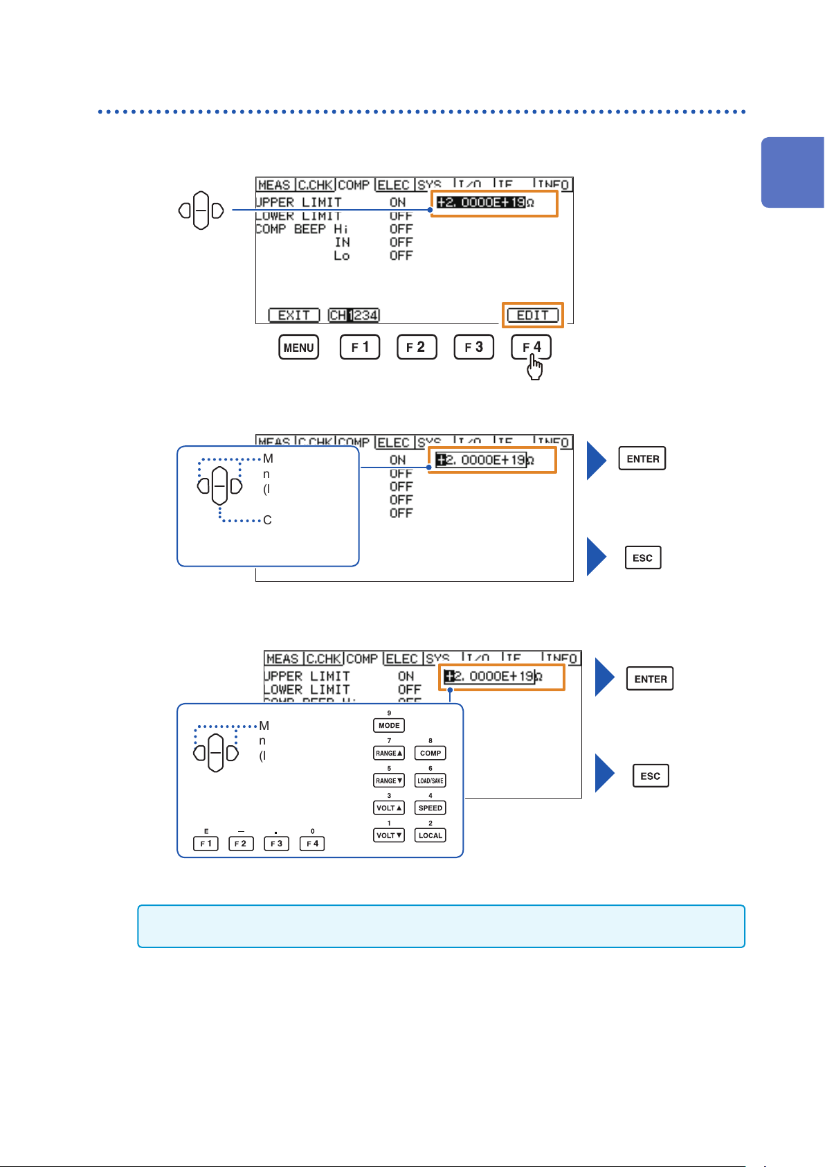
Methods for changing numerical values
The two options available are: using the cursor keys and using the numeric keypad.
Basic Key Operation
1
Move
(If using the cursor keys)
2
Move to the
next digit
(left or right)
Change the
numerical value
(up or down)
1
Overview
Conrm
Cancel
(If using the numeric keypad)
Conrm
Move to the
next digit
(left or right)
Cancel
If you press the ESC key while changing the numerical value, the numerical value change will be canceled.
If you press the ENTER key, the changed content is conrmed.
25
 Loading...