

Page 1

CAN EDITOR
HIOKI SF1002A961-00
Instruction Manual
Feb. 2022 Edition 1
SF1002A961-00 22
02H
-
EN
*600628910*
Page 2

HIOKI SF1002A961-00
Page 3

HIOKI SF1002A961-00
Contents
Introduction .......................................... 1
Trademarks .......................................... 1
Safety standards and notations ......... 1
Mouse operation .................................. 2
Precautions related to disc usage ...... 2
1 Overview 3
1.1 CAN Editor Overview .................. 3
1.2 Settings and Measurement
Procedure ..................................... 3
4.1 Main Screen Configuration ....... 15
4.2 Menu Bar .................................... 16
4.2.1 Opening the settings file .................... 16
4.2.2 Settings dialog box ............................. 17
4.2.3 Help .................................................... 17
4.3 Logger Information and
Send/Receive Information ......... 18
4.3.1 Search ................................................ 19
4.3.2 Manual register .................................. 19
4.3.3 Logger information ............................. 20
4.3.4 Unit configuration change .................. 20
5 Configuring CAN Unit
2 Installing CAN Editor 4
2.1 System Requirements for CAN
Editor ............................................ 5
2.2 Preparing the Installer ................ 5
2.2.1 Using the installer from the CD that
comes with the Logger ......................... 5
2.2.2 Using the installer from the HIOKI
website ................................................. 5
2.3 Installing CAN Editor .................. 6
2.4 Connecting the Logger and
PC Using a USB Cable ................ 8
2.4.1 Installing the USB driver ....................... 8
2.4.2 Connecting the Logger and PC
using a USB Cable ............................... 8
2.5 Uninstalling CAN Editor .............. 9
3 Starting Up CAN
Editor and Preparing
the Logger 10
3.1 Preparing for Measurement ...... 11
3.1.1 When connecting the Logger using
a USB cable ....................................... 11
3.1.2 When connecting the Logger using
a LAN cable ........................................ 11
3.1.3 When using the settings file ............... 11
3.2 Starting up CAN Editor ............. 12
3.3 CAN Editor Initial Selection
Screen ........................................ 13
3.3.1 Selecting the unit to be used .............. 14
Settings 21
5.1 Selecting the CAN Unit .............. 22
5.2 CAN Unit Setting Items ............. 23
5.3 Setting the Mode of the CAN
Unit .............................................. 23
5.4 Setting the Communication
Method of the CAN Unit ............ 24
5.5 CAN Unit Settings ...................... 26
5.6 Copying the CAN Unit
Settings ...................................... 26
6 Setting the Channels
(Receive Mode) 27
6.1 CAN Unit Channel Setting
Screen ......................................... 28
6.2 Display Selection Tab ................ 28
6.3 Receive CAN Data ...................... 29
6.3.1 Dialog box for editing CAN signal
receive channel .................................. 30
6.3.2 Import dialog box ............................... 33
6.3.3 Delete ................................................. 35
6.3.4 CAN data receive menu ..................... 36
6.3.5 Rearrange channels ........................... 37
6.3.6 Copy the selected channel settings ... 38
6.4 User Frame Transmission ......... 39
6.4.1 Dialog box for editing user frame
transmission ....................................... 40
6.4.2 Frame settings edit dialog box ........... 42
6.4.3 User frame menu ............................... 43
6.4.4 Frame settings menu ......................... 43
4 CAN Editor Main
SF1002A961-00
Screen 15
i
Page 4

HIOKI SF1002A961-00
7 Setting the Channels
(Measured Value
Output Mode) 44
7.1 Setting the CAN Unit Channels
(Measured Value Output
Mode) .......................................... 45
7.2 Loading the Measurement
Settings ...................................... 46
7.3 Assigning an ID Individually ..... 46
7.4 Assigning an ID All Together ... 47
7.5 Selecting the Channel to be
Output ........................................ 48
7.6 Selecting the Output Port ......... 48
7.7 Load Factor ................................ 48
7.8 Error ........................................... 49
7.9 Outputting the Measured
Value as a DBC File ................... 49
8 Updating the Logger
with CAN Settings 50
8.1 Sending the Settings from the
PC ............................................... 51
8.1.1 When there is a connected Logger .... 51
8.1.2 When there is no connected Logger .. 51
8.1.3 When the Logger is busy .................... 51
8.1.4 When the settings that do not allow
measurement to start are sent ........... 51
8.2 Loading the Settings File to
the Logger .................................. 52
8.2.1 Preparing media to be used ............... 52
8.2.2 Saving the settings file onto the
media .................................................. 52
8.2.3 Removing the media........................... 52
8.2.4 Loading the CES file to the Logger .... 52
9 Specifications 53
10 Knowledge and
Information 55
10.1 Load Factor of the Measured
Value Output Mode .................... 55
10.1.1 Number of frames that can be
transmitted on the CAN bus............... 55
10.1.2 Data volume to be transmitted on
the CAN bus ...................................... 55
10.2 Channel Type of the Receive
Mode ........................................... 56
10.2.1 When the channel type is set to
Data ................................................... 56
10.2.2 When the channel type is set to ID
count .................................................. 56
10.2.3 Examples of usage ............................ 57
10.3 User Frame Transmission
Operation .................................... 57
10.3.1 Relationship between user frame
No. and number of frames ................. 57
10.3.2 Relationship between scheduled
send ON and number of frames ........ 57
10.3.3 Output stop conditions ....................... 57
10.4 Counting the Bit Position .......... 58
10.5 Error and Warning Messages ... 60
10.5.1 Error message list .............................. 60
10.5.2 Warning message list ......................... 61
10.6 Setting the Logger on the PC ... 62
10.6.1 LAN connection (HTTP server
function) ............................................. 62
10.6.2 LAN/USB connection (Logger
Utility) ................................................. 62
10.7 No Communication with the
Logger ........................................ 62
10.7.1 When a USB connection is used ....... 62
10.7.2 When a LAN connection is used ........ 62
10.8 Open Source Software .............. 62
ii
Page 5

Model number
Model name
Supported CAN Unit
LR8450*1
Memory HiLogger
U8555 CAN Unit
LR8450-01*1
Memory HiLogger
U8555 CAN Unit
LR8535 Wireless CAN Unit
Safety notations
In this document, the severity levels of risk and hazard are classified as follows.
Indicates a potentially hazardous situation that, if not avoided,
damage to the supported product (or to other property).
from the standpoint of operating or maintaining the Logger.
Notation
(p. )
Indicates the page number to reference.
Indicates useful advice concerning instrument performance and
operation.
*
Indicates additional information is described below.
The names of user interface elements on the screen are enclosed
in brackets ([ ]).
Indicates the default setting. When initialized, the instrument will
revert to this value.
CURSOR
The bold alphanumeric characters in this manual indicate the
characters displayed on the PC keyboard.
Unless otherwise noted, the term “Windows” is used generically to
refer to Windows 10 or Windows 11.
Logger
Memory HiLoggers are referred to as “Logger” in this manual.
CAN Unit
U8555 and LR8535 are referred to as “CAN Unit” in this manual.
PC
Computers are referred to as “PC” in this manual.
HIOKI SF1002A961-00
Introduction
“CAN Editor” is an application software exclusively for the following instruments.
*1: Version 2.00 and later versions are supported.
For the Memory HiLoggers, refer to the instruction manuals that came with LR8450 and LR8450-01.
Trademarks
Microsoft and Windows are either registered trademarks or trademarks of Microsoft Corporation in the
United States and other countries.
Safety standards and notations
CAUTION
IMPORTANT
could result in minor or moderate injury, or potential risks of
Indicates information or content that is particularly important
[ ]
☑
(Bold letters)
Windows
1
Page 6

Click
Press and quickly release the left button of the mouse.
Right-click
Press and quickly release the right button of the mouse.
Double-click
Quickly click the left mouse button twice.
Drag
While holding down the left button of the mouse, move the mouse and then
release the left button to deposit the chosen item in the desired position.
Active
Click on a window on the screen to activate that window.
Exercise care to keep the recording surface of the disc free of dirt and
with the use of this disc.
HIOKI SF1002A961-00
Mouse operation
Precautions related to disc usage
CAUTION
damage. If you need to label the disc, for example with text, use a marker
with a soft tip.
Store discs in protective cases. Avoid exposing the disc to direct sunlight,
high temperatures, or high humidity.
Hioki is not liable for any computer system issues that arise in connection
2
Page 7

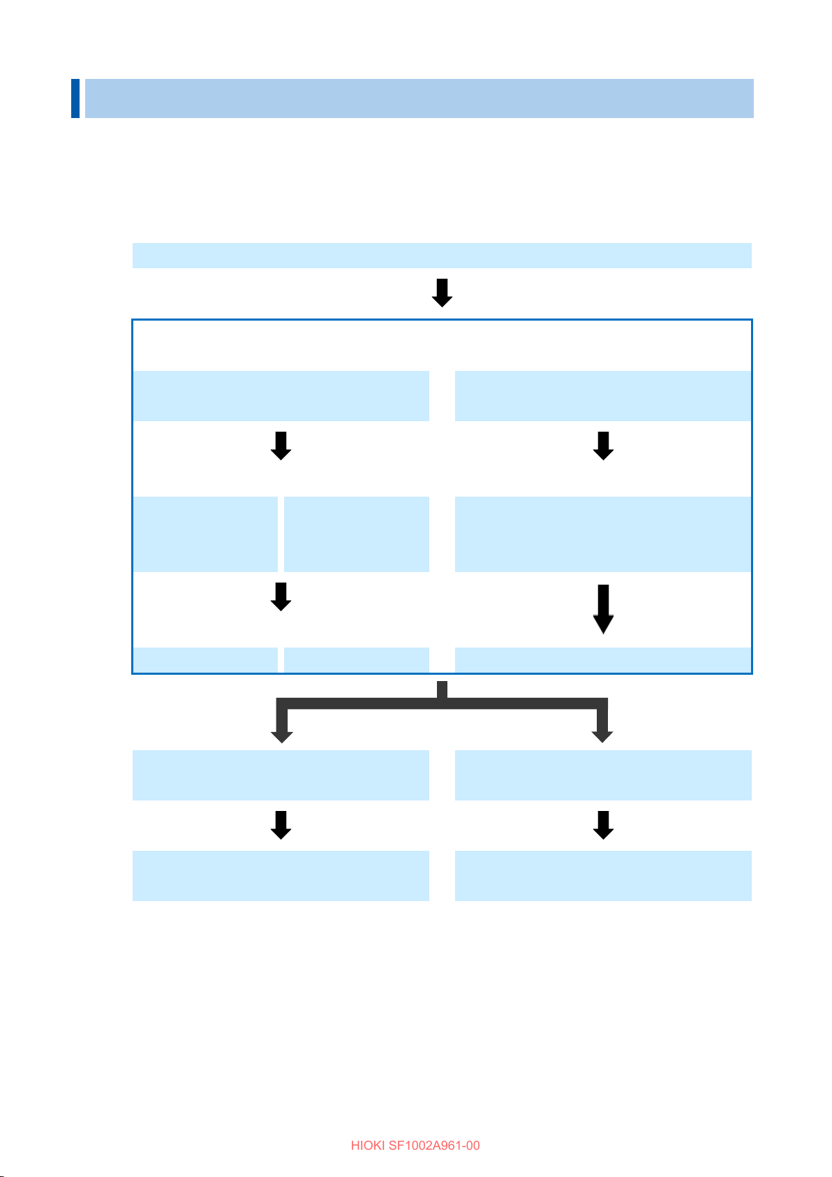
1. Installing CAN Editor on the PC (Chapter 2)
2. Starting up CAN Editor and preparing the Logger (Chapter 3)
3. Setting the CAN Unit (Chapter 5)
4. Setting the channels based on the CAN Unit mode
(1) Receive mode (Chapter 6)
(2) Measured value output mode
(Chapter 7)
5. Updating the Logger with the CAN settings (Chapter 8)
6. Starting and ending measurement (See the Logger operation procedure.)
(2) Finish the measurement
HIOKI SF1002A961-00
1 Overview
1.1 CAN Editor Overview
CAN Editor is application software for setting CAN signal measurements and output of the Logger to
which the CAN Unit is connected. The following operations can be performed when the CAN Unit is
set.
• Measures the CAN signals using the Logger.
• Sends a signal to the CAN bus from the Logger.
• Sends data measured using the Logger to the CAN bus (data measured with a plug-in module).
1.2 Settings and Measurement Procedure
The settings and measurement procedure are shown below.
(1) Check the CAN settings on the Logger and start measurement.
3
Page 8

1. Checking the operation environment for CAN Editor (2.1)
2. Preparing the installer (2.2)
3. Installing CAN Editor (2.3)
4. When connecting the Logger
When not connecting the Logger using
Installing the USB driver (2.4.1)
Connecting the Logger using a USB cable
(2.4.2)
5. Completing the installation
Uninstalling CAN Editor if necessary (2.5)
HIOKI SF1002A961-00
2 Installing CAN Editor
Install CAN Editor on the PC according to the following instructions.
The installation procedure described in this chapter is shown below.
using a USB cable
a USB cable
4
Page 9

OS
Windows 10 (32 bits/64 bits) / Windows 11 (64 bits)
CPU
1 GHz or faster 32 bit (x86) or 64 bit (x64) processor
Display
1280 × 1024 dots or more
65,536 colors or more
Memory
2 GB or more
Hard disk
3 GB or more of available space
Interface
With an Ethernet or USB terminal
Required framework
Microsoft .NET Framework 4.6 and a language pack applicable for the
execution environment must be installed.
HIOKI SF1002A961-00
2.1 System Requirements for CAN Editor
Before installing CAN Editor, check the system requirements of the PC.
2.2 Preparing the Installer
CAN Editor can be installed in the following two methods.
2.2.1 Using the installer from the CD that comes with the Logger
Install CAN Editor using the installer from the CD that comes with the Logger.
2.2.2 Using the installer from the HIOKI website
Install CAN Editor using the installer downloaded from Hioki’s website.
The latest installer for CAN Editor can be downloaded.
https://www.hioki.com/global
5
Page 10

IMPORTANT
Click
Click
HIOKI SF1002A961-00
2.3 Installing CAN Editor
The procedure for installing CAN Editor is described in this section.
Displayed messages and operations may be different depending on the operating system or settings.
If any anti-virus software is running, make sure to close it before starting the installation. If anti-virus
software is running, the software may not be installed properly.
1. Start up Windows
Close all the software that is running.
®
.
2. Set the supplied CD in the CD-ROM
drive.
The Logger Application Disc page is
displayed.
Select a language and select [CAN
Editor] → [Install].
3. Select the language to use for the
installation and click [OK].
The procedure for when English is
selected is described in this manual.
4. Click [Next]. Accept the license
agreement and then click [Next].
Check
Click
When the Logger Application Disc
page is not displayed
Execute [index.htm] on the CD. If a dialog
box asking for permission for application
installation is displayed, click [Allow] and
proceed.
6
Page 11

Click
HIOKI SF1002A961-00
5. Click [Next].
Installation starts.
How to change the installation
destination
Click [Change] and change the folder to
which CAN Editor is to be installed. Normally
this setting does not need to be changed.
The installation is now complete.
Click
7
Page 12

CAUTION
Click
Click
HIOKI SF1002A961-00
2.4 Connecting the Logger and PC Using a USB Cable
2.4.1 Installing the USB driver
When connecting the Logger using a USB cable, install the USB driver.
1. Install the USB driver.
Execute [DriverSetupWin10.msi] in the
USB Driver folder on the CD.
If CAN Editor has already been installed,
execute the program at the following
location.
[C:¥Program Files (x86)¥HIOKI¥ CAN
Editor for MEMORY HiLOGGER¥
Driver¥DriverSetupWin10.msi]
Please wait as it may take time for a dialog
box to be displayed depending on the PC.
If the installation destination has been
changed, refer to the location.
2. Click [Continue].
When a dialog box asking for permission
for application installation is displayed,
click [Continue] and proceed.
3. Click [Install].
If a dialog box asking for permission for
application installation is displayed, check
the [Always trust software from “HIOKI
E.E. CORPORATION”] check box and
click [Install] to proceed.
4. When the installation is completed and
the following dialog box is displayed,
click [Close].
The driver installation is now complete.
2.4.2 Connecting the Logger and PC using a USB Cable
After installing the USB driver, connect the Logger and PC using a USB cable.
Do not plug in or unplug the USB cable while the instrument is operating.
1. Connect the AC adapter to the Logger and turn on the power.
2. Connect the PC and Logger using the provided USB cable.
The Logger is automatically recognized and the preparation to use the Logger is completed.
8
Page 13

The settings files, etc. remain unchanged. Delete them manually if they are not needed.
The uninstallation is
now complete.
(1) Right-click.
(2) Click.
Click
Click
Click
HIOKI SF1002A961-00
2.5 Uninstalling CAN Editor
The procedure for uninstalling CAN Editor is described in this section.
Right-click the Start button of Windows® and then click [Apps and Features].
1.
From the displayed application list, select and click [CAN Editor].
2.
Click this button to display [Uninstall].
Click [Uninstall].
3.
The installer starts automatically.
Click this button to display the confirmation dialog box.
The [Apps and Features] dialog box is displayed again.
9
Page 14

When connecting the Logger and PC
When not connecting the Logger and PC
Preparing for measurement (3.1)
When using a
(3.1.1)
When using a
(3.1.2)
When using the
(3.1.3)
When setting
When using
settings
Connecting the
Connecting
LAN
Preparing the
Starting up CAN Editor (3.2)
Initial selection screen (3.3)
When setting CAN Editor online
When setting CAN Editor offline
Selecting the
continue
Communicating with LR8450 to
Opening the
Selecting the
To the CAN Editor main screen (Chapter 4)
HIOKI SF1002A961-00
3 Starting Up CAN Editor and Preparing
the Logger
The procedure from starting up CAN Editor to starting Logger settings is shown below.
USB cable
cable
LAN cable
the cable
Setting the
settings file
settings file
manually
the previous
previous
settings to
receive the unit configuration
settings file
unit to be used
10
Page 15

Settings file that can be loaded
File extension
Settings file that has been saved in the Logger
.SET
Settings file that has been saved in CAN Editor
.CES
HIOKI SF1002A961-00
3.1 Preparing for Measurement
Make all the settings except for the CAN Unit on the Logger in advance.
3.1.1 When connecting the Logger using a USB cable
Prepare a USB cable and connect the Logger and PC with CAN Editor installed.
The USB driver needs to be installed.
See “2.4.1 Installing the USB driver”
3.1.2 When connecting the Logger using a LAN cable
Prepare a LAN cable and connect the Logger and PC with CAN Editor installed.
The LAN communication needs to be set.
See “9.3 Configuring and Establishing a LAN Connection” in Logger Instruction Manual
3.1.3 When using the settings file
Prepare the settings files that can be loaded to CAN Editor.
11
Page 16

Click
HIOKI SF1002A961-00
3.2 Starting up CAN Editor
From the Windows® Start menu, click [HIOKI] - [CAN Editor].
The initial selection screen is displayed when CAN Editor starts up.
See “3.3 CAN Editor Initial Selection Screen”
1.
Click
2.
Click
3.
Starting up CAN Editor while holding down the Shift key starts up the application at the initial position
and in the initial size.
12
Page 17

1 Communicate with LR8450
Connects the Logger using a USB or LAN cable and receives
See “4.3.1 Search”
2 Open the settings file
Loads the settings file.
See “3.1.3 When using the settings file”
3 Select the unit to be used
Registers the CAN Unit.
See “3.3.1 Selecting the unit to be used”
4 Continue previous settings
Continues from the previous setting of CAN Editor.
5 Do not show this screen
When this check box is checked, this dialog box is not displayed
See “4.1 Main Screen Configuration”
1 2 3 4 5
HIOKI SF1002A961-00
3.3 CAN Editor Initial Selection Screen
The initial selection screen is displayed when CAN Editor starts up.
If the [Do not show this screen again] check box (5 shown below) was checked when CAN Editor
was used the last time, the main screen is displayed.
Select how to set CAN Editor.
to receive settings
again
the Logger settings.
at the time of startup and the main screen is displayed.
Continues from the previous setting of CAN Editor.
13
Page 18

HIOKI SF1002A961-00
3.3.1 Selecting the unit to be used
Clicking [Select the unit to be used] displays the unit selection screen.
Up to four units for which CAN settings are to be configured can be selected.
The unit configuration can be changed later on.
See “4.3.4 Unit configuration change”
14
Page 19

1 Display change, close
Changes the CAN Editor display or ends CAN Editor.
is clicked.
2 Menu bar
Displays the menu bar (list) of CAN Editor.
See “4.2 Menu Bar”
3 Logger information and
Displays the information of the units connected to the Logger.
See “4.3 Logger Information and Send/Receive Information”
4 Setting-title information
Allows you to enter a setting title.
5 CAN Unit information
Displays the information of the unit to be set.
See “5 Configuring CAN Unit Settings”
6 CAN channel information
Displays the information of the channel to be set.
Channels (Measured Value Output Mode)”
2 3 4 6 5
1
HIOKI SF1002A961-00
4 CAN Editor Main Screen
4.1 Main Screen Configuration
The configuration of the main screen is shown below.
buttons
send/receive information
If the dialog box is displayed, it is closed when [×] of the dialog box
Select the units that send/receive the settings to/from the Logger.
See “6 Setting the Channels (Receive Mode)”, “7 Setting the
15
Page 20

1 New
Discards the information that is being set and sets new information.
Registered Logger information is also discarded.
2 Open
Loads the settings file.
See “4.2.1 Opening the settings file”
3 Save
Saves the CAN Editor settings as a settings file (CES file).
4 Settings
Opens the CAN Editor settings dialog box.
See “4.2.2 Settings dialog box”
5 Help
Opens the Help information.
See “4.2.3 Help”
5
1
3
4
2
HIOKI SF1002A961-00
4.2 Menu Bar
The configuration of the main bar is shown below.
See “3.1.3 When using the settings file”
4.2.1 Opening the settings file
If the unit configuration of the settings file is the same as that of CAN Editor, clicking [Open] displays
the following dialog box.
Select the settings to be loaded and click [Confirm] to load the settings.
If the unit configuration of the settings file is different from that of CAN Editor, the following dialog box
is displayed. Clicking [OK] initializes the settings of the measured value output mode after the settings
are loaded.
16
Page 21

1 Open the instruction manual
Opens the CAN Editor instruction manual.
2 CAN editor version information
Opens the CAN Editor version information.
1
2
1
2
HIOKI SF1002A961-00
4.2.2 Settings dialog box
Clicking [Settings] displays the following dialog box.
1. Parameter
Clicking an item displays the setting details at the right side of the dialog box.
2. Setting details display
Configures various settings.
4.2.3 Help
Clicking [Help] displays the following items.
17
Page 22

1 Search
Searches for the Logger to be set. (USB connection, LAN connection)
See “4.3.1 Search”
2 Logger information
Displays the information of the Logger to be set.
See “4.3.3 Logger information”
3 Receive
Receives the unit configuration and CAN settings from the Logger to be
set.
4 Unit configuration
Displays the information of the unit connected to the Logger.
Select the units that send/receive the settings to/from the Logger.
5 Send
Transfers the information set by CAN Editor to the Logger to be set.
1
2
3
4
5
HIOKI SF1002A961-00
4.3 Logger Information and Send/Receive Information
The Logger information and send/receive information configuration are shown below.
18
Page 23

1 Search
Performs a search again.
2 Register
Registers the selected Logger.
3 Cancel
Closes the dialog box without registering the Logger.
4 Manual
Registers a Logger manually when no Logger is found.
See “4.3.2 Manual register”
1 2 4
3
HIOKI SF1002A961-00
4.3.1 Search
The Logger connected using a USB or LAN cable is searched.
The search result list is displayed.
4.3.2 Manual register
Clicking [Manual] displays the following dialog box.
• LAN: Enter the IP address and port number set in the Logger. For the port number, enter the first
three digits out of four digits or five digits.
The last digit cannot be specified.
• USB: Select the COM port.
Click [Register] to start connection.
19
Page 24

1 Logger name
Registered Logger name
2 Serial number
Serial number of the registered Logger
3 Communication interface
Type of communication interface of the registered Logger
When a LAN cable is used, the port number is also displayed.
4 Port or IP address
Displays the following depending on the communication interface.
LAN: IP address
Configuration change
check box
Specifies the unit with the check box checked as a CAN unit. Only
units that are not yet registered can be selected.
1
2 3 4
HIOKI SF1002A961-00
4.3.3 Logger information
Registered Logger information is displayed.
USB: Port number
4.3.4 Unit configuration change
The information of the unit to be set is displayed.
20
Page 25

Selecting the CAN Unit to be set (5.1)
Setting the mode of the CAN Unit (5.3)
Receive mode
Measured value output mode
Setting the communication method of the CAN Unit (5.4)
Setting the update interval of the CAN Unit (5.5)
To Chapter 6
To Chapter 7
HIOKI SF1002A961-00
5 Configuring CAN Unit Settings
The procedure for configuring CAN Unit settings is shown below.
21
Page 26

1 Unit selection
Clicking the CAN Unit opens the CAN Unit setting screen.
Only the CAN Unit can be selected.
2 CAN Unit setting items
Displays the settings of the selected CAN Unit.
See “5.2 CAN Unit Setting Items”
3 CAN channel setting
items
Displays the channel settings of the selected CAN Unit.
1
2
3
HIOKI SF1002A961-00
5.1 Selecting the CAN Unit
Specify various settings of the CAN Unit in the CAN Unit setting screen.
22
Page 27

1 Mode setting
Allows you to select the CAN Unit mode.
See “5.3 Setting the Mode of the CAN Unit”
2 CAN bus settings
Specifies the CAN bus.
See “5.4 Setting the Communication Method of the CAN Unit”
3 CAN Unit setting
Specifies the data refresh interval of the CAN Unit.
See “5.5 CAN Unit Settings”
1 Receive mode☑
Measures a signal flowing in the CAN bus.
See Chapter 6 for setting the channels after setting the CAN Unit.
2 Measured value
Outputs the measured value of the Logger (plug-in module) to the CAN
See Chapter 7 for setting the channels after setting the CAN Unit.
2
2 3 1
1
HIOKI SF1002A961-00
5.2 CAN Unit Setting Items
The configuration of the CAN Unit setting screen is shown below.
5.3 Setting the Mode of the CAN Unit
Select whether to set the CAN Unit in the receive mode or measured value output mode.
The mode can be selected for each CAN Unit. Only the plug-in CAN Unit can be selected in the
measured value output mode. (Wireless units can be set only in the receive mode.)
A signal is output to the CAN bus. The signal can be output while the
CAN signal is measured.
output mode
bus.
23
Page 28

CAN
Sets the CAN mode.
CAN FD☑
Sets the CAN FD mode. (ISO 11898-1:2015 compliant)
CAN FD(non-ISO)
Sets the CAN FD (non-ISO) mode. (not ISO compliant)
The ACK is fixed to ON in this mode.
ON
Sends ACK frame from the CAN controller.
OFF☑
Does not send ACK frame from the CAN controller.
measured value output mode.
ON
Terminates the CAN bus using a 120 Ω resister between CAN_H and
CAN_L.
OFF☑
Opens the CAN bus between CAN_H and CAN_L.
50 k, 62.5 k, 83.3 k, 100 k, 125 k, 250 k, 500 k☑, 800 k, 1000 k (Baud)
50.0% to 95.0%, 80.0%☑
1 2 3 4 5 9 8 6 7
HIOKI SF1002A961-00
5.4 Setting the Communication Method of the CAN Unit
Clicking [Edit] opens the communication settings edit screen.
The settings edit screen is shown below. The ports to be used are set on this screen.
1. Select the interface.
2. Select the ACK.
3. Select the terminator.
4. Select the baud rate.
5. Set the sampling point.
The instrument will not be able to send user frames or operate in
24
Page 29

0.5 M, 1.0 M, 2.0 M☑, 2.5 M, 4.0 M, 5.0 M (Baud)
50.0% to 95.0%, 80.0%☑
HIOKI SF1002A961-00
6. Select the data rate (when the interface is not CAN).
7. Set the data sampling point (only when the interface is not CAN).
8. Sampling point value to be set
For the sampling point, a value that can be set varies depending on the baud rate.
The sampling point that can be set and is the closest to the value input on the edit screen is
displayed.
This value is displayed in 5 “Sampling point”.
9. Data sampling point value to be set
For the data sampling point, a value that can be set varies depending on the data rate.
The data sampling point that can be set and is the closest to the value input on the edit screen is
displayed.
This value is displayed in 7 “Data sampling point”.
25
Page 30

8 double-byte characters, 16 single-byte characters
10 ms, 20 ms, 50 ms, 100 ms☑, 200 ms, 500 ms, 1 s, 2 s, 5 s, 10 s
Data refresh interval
Number of channels that can be measured
10 ms
Up to 50 channels
20 ms
Up to 100 channels
50 ms
Up to 250 channels
100 ms or greater
Up to 500 channels
1
2
HIOKI SF1002A961-00
5.5 CAN Unit Settings
Specifies the data refresh interval of the CAN Unit.
1. The unit identifier set in the Logger is displayed.
2. Select the data refresh interval.
The number of channels that can be measured varies depending on the selected data refresh
interval.
5.6 Copying the CAN Unit Settings
Right-clicking the CAN Unit opens the menu. Clicking [Copy CAN Unit settings] allows you to
copy the CAN Unit settings.
Right-clicking the CAN Unit with the CAN Unit settings copied opens the menu with the settings of
[Paste copied settings] added. Clicking [Paste copied settings] reflects the CAN Unit settings
and receive mode settings. Only the CAN Unit with the check box checked can be copied.
26
Page 31
Switching the display tabs (6.2)
HIOKI SF1002A961-00
6 Setting the Channels (Receive Mode)
The channels of the CAN Unit set in the receive mode are set here.
The CAN Unit in the receive mode can receive CAN signals and sends user frames to the CAN bus.
The procedure for setting the receive mode is shown below.
Checking the entire channel setting screen (6.1)
CAN signal receive settings display
Checking the CAN signal receive screen
(6.3)
Adding a channel
Manually adding a
channel (6.3.1)
As needed
Edit (6.3.1) Delete (6.3.3)
When there are other CAN Unit settings
Importing the
definition from the
file (6.3.2)
User frame output settings display
Checking the user frame output screen
(6.4)
Adding frame output
Add (6.4.1)
Frame settings edit (6.4.2)
When there are no other CAN Unit
Configuring other CAN Unit settings as
well
27
settings
Updating the Logger with the CAN Unit
settings (Chapter 8)
Page 32

1 Display selection tab
Switches the displayed items between CAN data receive and user
See “6.2 Display Selection Tab”
2 Channel settings
Displays the channel settings and processing.
tab.
3 Channel settings list
Displays the list of channel settings.
tab.
1 Receive CAN data
Displays the information required for the CAN data receive settings.
See “6.3 Receive CAN Data”
2 User frame
Displays the information required for the user frame transmission
See “6.4 User Frame Transmission”
1 1 2
2
3
HIOKI SF1002A961-00
6.1 CAN Unit Channel Setting Screen
The configuration of the channel setting screen is shown below.
frame transmission.
The information varies depending on the selected display selection
The information varies depending on the selected display selection
6.2 Display Selection Tab
Receive CAN data and user frame transmission display are switched.
transmission
settings.
28
Page 33

1 Add
Assigns the CAN data receive channels to the CAN Unit.
See “6.3.1 Dialog box for editing CAN signal receive channel”
2 Import
Assign the CAN signal receive channels from the CAN data definition
See “6.3.2 Import dialog box”
3 Receiving size
Displays the total receiving size and maximum receiving size that can be
The receiving size for each channel varies depending on the setting.
4 Delete
Deletes the information of the channels registered in the selected
See “6.3.3 Delete”
5 Channel list
Displays a list of registered channel settings.
See “6.3.4 CAN data receive menu”
6 Use
Measures the registered channels with the check box checked.
7 Ch
For the channels with the [Use] check box checked, the button of the
See “6.3.1 Dialog box for editing CAN signal receive channel”
7
6
1 4 2 3 5
HIOKI SF1002A961-00
6.3 Receive CAN Data
When the “Receive CAN data” tab is selected, the following items are displayed.
See “6.2 Display Selection Tab”
file.
registered of all the channels of the selected CAN Unit.
Channels can be registered up to the maximum receiving size.
The maximum receiving size varies depending on the CAN Unit update
interval.
CAN Unit.
The menu is displayed when the right button of the mouse is clicked.
target channels can be clicked. The settings of the target channels
can be edited.
29
Page 34

Port 1☑
Measures the CAN signals received by Port 1.
Port 2
Measures the CAN signals received by Port 2.
Up to 20 double-byte characters or 40 single-byte characters
Up to 3 double-byte characters or 7 single-byte characters
Data☑
Converts the CAN data to a physical quantity and records the data.
ID count
Counts the number of times the specified ID is received.
The counter is reset to 0 at the data refresh interval.
1 2 3 4 5 6 7 8 9
10
11
12
13
14
15
16
17
20
18
19
HIOKI SF1002A961-00
6.3.1 Dialog box for editing CAN signal receive channel
Clicking [Add] or the [Ch] button for the channel to be edited displays the following dialog box.
The settings that were determined previously after CAN Editor started up are displayed as default
settings.
When there are no previously determined settings, the default value of each item is displayed.
1. Select the port to be measured.
2. Set the comment (as needed).
3. Set the unit.
4. Select the channel type.
30
Page 35

Standard☑
Expresses the ID by 11 bits.
Extended
Expresses the ID by 29 bits.
[Standard] format: 0h☑ to 7FFh, [Extended] format: 0h☑ to 1FFFFFFFh
Motorola☑
Format sending the upper byte first (big endian)
Intel
Format sending the lower byte first (little endian)
Unsigned☑
Unsigned integer type
Signed
Signed integer type
IEEE Float
Single-precision floating-point format
IEEE Double
Double-precision floating-point format
1 to 64, 2☑
0☑ to 511
Factor
Allows you to enter the factor and offset for converting data to a physical
(Default value: Factor 1.0, offset 0.0)
Offset
HIOKI SF1002A961-00
5. Select the ID format.
6. Set the ID.
Set the ID using a hexadecimal number.
7. The value of the set ID is expressed as a decimal number.
8. Select the byte order.
9. Set the data type.
10. Set the length.
When the data type is IEEE Float, the length is fixed to 32.
When the data type is IEEE Double, the length is fixed to 64.
11. Set the start bit.
The setting range varies depending on the byte order and length settings.
12. Set the factor and offset.
quantity.
A physical quantity can be calculated using the following formula.
(Physical quantity) = (Factor) × (Data) + (Offset)
13. Auto (Factor and Offset)
The factor and offset are automatically set so that the measured value can change in the range
from the upper limit to the lower limit.
This is enabled only when the data type is signed and unsigned.
31
Page 36

Upper
Specifies the upper limit of the waveform displayed on the Logger screen.
Default: 1.0
Lower
Specifies the lower limit of the waveform displayed on the Logger screen.
Default: -1.0
0 to 10, 3
Decimal☑
Specifies the number display format of the Logger to a decimal.
Exponent
Specifies the number display format of the Logger to an exponent.
OFF, 24 colors
Confirm
Reflects the settings in the dialog box and closes the dialog box.
Cancel
Discards the settings in the dialog box and closes the dialog box.
HIOKI SF1002A961-00
14. Set the upper and lower limits.
15. Auto (Upper and Lower)
The minimum value is automatically set as the lower limit and the maximum value is automatically
set as the upper limit within the range of the measured value.
16. Select the number of digits.
☑
The number of decimal places for the measured value displayed in the Logger is set.
The default value is 0 when the channel type is ID count.
17. Select the format.
18. Select the display color.
19. Set the threshold value.
The threshold value for numerical calculation is set.
20. Confirm the settings in the dialog box.
32
Page 37

Open
Allows you to select a file.
File available for import
File extension
DBC file*1
.DBC
Logger settings file
.SET
CAN Editor settings file
.CES
Definition file created by MR8904 CAN Editor
.CDF
Port 1
Adds definitions with Port 1 to be used.
Port 2
Adds definitions with Port 2 to be used.
1 2 4 5 9 6 11
10 3 7
8
HIOKI SF1002A961-00
6.3.2 Import dialog box
Clicking [Import] displays the following dialog box.
1. Select the file to be imported.
*1: The Chinese characters code is only available for Shift_JIS.
2. List of import file definitions
A list of definitions existing for the import file is displayed.
Select the definition to be added to the measurement channel.
Clicking the definition while holding down the Ctrl key on the keyboard allows you to select multiple
channels.
3. Import file information
Clicking the item other than No. sorts the definition list of that item.
4. Select the port to be added.
5. Comment
Check the check box to add a definition in the form of “Signal name + Comment” as an import file
definition to the channel comment.
Default: Check box checked
33
Page 38

Data>>
Registers the channel type as data.
ID count>>
Registers the channel type as ID count.
Confirm
Reflects the settings in the dialog box and closes the dialog box.
Cancel
Discards the settings in the dialog box and closes the dialog box.
HIOKI SF1002A961-00
6. Add
Definitions can be dragged from the definition list and dropped to the registered channel list to be
registered as data.
Up to 500 definitions can be registered for one unit.
7. Receiving size
The status of the receiving size registered in the CAN Unit is displayed.
8. Delete
Deletes the information of the channels registered in the selected CAN Unit.
See “6.3.3 Delete”
9. Registered channel list
The information of the imported channels is displayed as a preview.
10. Number of signals
The number of the imported signals is displayed.
11. Confirm the settings in the dialog box.
34
Page 39

Confirm
Deletes the settings in the dialog box and closes the dialog box.
Cancel
Closes the dialog box without deleting the settings.
1 2 3
HIOKI SF1002A961-00
6.3.3 Delete
Selecting this menu displays the following dialog box.
1. Delete selected channels in the unit.
Deletes the selected channels.
2. Delete all channels in the unit.
Deletes all of the channels registered in the unit.
3. Confirm the settings in the dialog box.
35
Page 40

2
3
1
4 5 6
HIOKI SF1002A961-00
6.3.4 CAN data receive menu
The following menu is displayed when the right button of the mouse is clicked in the channel list area.
1 Add
Assigns the CAN data receive channels to the CAN Unit.
See “6.3.1 Dialog box for editing CAN signal receive channel”
2 Replace the selected channel with one above
Replaces the selected channel with one above.
It is enabled when only one channel is selected.
3 Replace the selected channel with one below
Replaces the selected channel with one below.
It is enabled when only one channel is selected.
4 Rearrange channels
Clicking this menu displays a dialog box for rearranging the channels.
See “6.3.5 Rearrange channels”
5 Copy the selected channel settings
Clicking this menu displays a dialog box for copying the selected channel settings.
See “6.3.6 Copy the selected channel settings”
6 Set the display color to standard
Specifies the display color to the standard setting.
Set the display color of the channels with the “Use” check box checked that are registered in the
unit in order of color 1 to 24.
36
Page 41

Ascending order
Rearranges the channels in the ascending order.
Descending
order
Rearranges the channels in the descending order.
Confirm
Rearrange the channels based on the settings in the dialog box
Cancel
Closes the dialog box without rearranging the channels.
1
2
3
4
HIOKI SF1002A961-00
6.3.5 Rearrange channels
The order of the channels registered in the unit is rearranged.
1. Rearrangement condition
Use, Comment, Unit, Port, Ch type, ID, Format, Start bit, Length, Byte order, Value
type, Factor, Offset, Upper, Lower, Digit, Format, Display color, Threshold
Select the conditions for rearrangement.
2. Order
3. Set the display color to standard
Specifies the display color to the standard setting after the order of the channels with the check box
checked is rearranged. Set the display color of the channels with the “Use” check box checked that
are registered in the unit in order of color 1 to 24.
4. Confirm the settings in the dialog box.
37
Page 42

Copy the selected settings to other channels in the same unit.*1
Copy all settings to other channels in the same unit.
Port
Copies the settings to a channel with the same port as that of the channel to
be copied.
Ch type
Copies the settings to a channel with the same channel type as that of the
channel to be copied.
Confirm
Copies the settings in the dialog box and closes the dialog box.
Cancel
Closes the dialog box without copying the settings.
1
2 3 4
5
HIOKI SF1002A961-00
6.3.6 Copy the selected channel settings
The settings of the selected channels are copied to other channels in the unit.
1. Select the settings to be copied.
*1: Any condition settings that cause an error in other channels are not copied.
2. Original
Displays the channel to be copied.
3. Conditions
The condition can be set when [Copy the selected settings to other channels in the same unit]
is selected.
4. Copy items
Copies the settings of the items with the check box checked.
The condition can be set when [Copy the selected settings to other channels in the same unit]
is selected.
5. Confirm the settings in the dialog box.
38
Page 43

1 User frame list
Displays the user frame transmission settings.
See “6.4.3 User frame menu”
2 Use
Outputs the selected frames.
3 User frame No.
[No.] is available when the user frame transmission is enabled.
See “6.4.1 Dialog box for editing user frame transmission”
1
2
3
HIOKI SF1002A961-00
6.4 User Frame Transmission
When the [User frame transmission] tab is selected, the following items are displayed.
See “6.2 Display Selection Tab”
The menu is displayed when the right button of the mouse is clicked.
The user frame settings are configured.
39
Page 44

Port 1☑
Sends a user frame from Port 1.
Port 2
Sends a user frame from Port 2.
Start☑
Starts transmission at the start of measurement.
Stop
Sends only one frame for every condition when measurement is stopped.
Periodic and two or more frames cannot be set.
Start trigger
Starts transmission when a start trigger is set.
Alarm
Starts transmission when an alarm is set.
Manual
Starts transmission when the operation in the Logger CAN frame transmission
See “1.5 Configuring CAN Settings” in Logger Instruction Manual
All ALM☑, ALM1, ALM2, ALM3, ALM4, ALM5, ALM6, ALM7, ALM8
1☑ to 9999
1☑, 2, 3, 4, 5, 6, 7, 8
1 2 4
6 7 9 8 5
3
HIOKI SF1002A961-00
6.4.1 Dialog box for editing user frame transmission
Clicking [No.] displays the following dialog box.
1. Select the port to be used.
2. Timing
dialog box is performed.
3. Target alarm
4. Periodic
Checking the check box repeats transmission periodically after all frames are sent. If the check box
is not checked, all frames are sent only once.
Default: Check box not checked
5. Send interval
This setting is available only when Periodic is ON. The send interval is the set value × 10 ms.
6. Frame
40
Page 45
Confirm
Reflects the settings in the dialog box and closes the dialog box.
Cancel
Discards the settings in the dialog box and closes the dialog box.
HIOKI SF1002A961-00
7. Frame setting list
Only frames for the number of frames set in Frame are displayed.
The menu is displayed when the right button of the mouse is clicked.
See “6.4.4 Frame settings menu”
8. Frame number
Clicking the frame number button opens the frame settings edit dialog box.
See “6.4.2 Frame settings edit dialog box”
9. Confirm the settings in the dialog box.
41
Page 46

CAN Standard☑
Standard ID (0h to 7FFh) CAN frame
CAN Extended
Extended ID (0h to 1FFFFFFFh) CAN frame
CAN FD Standard
Standard ID (0h to 7FFh) CAN FD frame
CAN FD Extended
Extended ID (0h to 1FFFFFFFh) CAN FD frame
[CAN Standard] or [CAN FD Standard] type: 0h☑ to 7FFh
[CAN Extended] or [CAN FD Extended] type: 0h☑ to 1FFFFFFFh
Frame 1: 0☑ to 9999, Frame 2 and subsequent frames: 1☑ to 9999
1 8 9 2 3 4 5 6 7
HIOKI SF1002A961-00
6.4.2 Frame settings edit dialog box
Clicking the frame number in the User frame transmission settings dialog box displays the following
dialog box.
1. Select the type.
2. Set the ID.
Set the ID using a hexadecimal number.
3. The value of the set ID is expressed as a decimal number.
4. Set the delay time.
The delay time is the set value × 10 ms.
42
Page 47

0, 1☑, 2, 3, 4, 5, 6, 7, 8, 9, 10, 11, 12, 13, 14, 15
0h☑ to FFh
Confirm
Reflects the settings in the dialog box and closes the dialog box.
Cancel
Discards the settings in the dialog box and closes the dialog box.
HIOKI SF1002A961-00
5. Select the DLC.
6. The byte size of the data corresponding to the specified DLC is displayed.
7. The data list is displayed. The data can be edited up to the byte length specified in DLC.
8. Set the data.
Set the data using a hexadecimal number one byte at a time.
9. Confirm the settings in the dialog box.
6.4.3 User frame menu
The following menu is displayed when the right button of the mouse is clicked in the user frame list
area.
All settings of the selected condition are copied to other conditions within the same unit.
6.4.4 Frame settings menu
The following menu is displayed when the right button of the mouse is clicked in the frame settings list
area.
All settings of the selected frame are copied to other frames within the same condition.
43
Page 48

Checking the entire CAN Unit channel setting screen (7.1)
Loading the measurement settings (7.2)
Assigning an ID
Assigning an ID individually (7.3)
Assigning an ID all together (7.4)
Load factor (7.7)
As needed
Setting the output
channel (7.5)
Setting the output
port (7.6)
Outputting the measured value as a DBC file (7.9)
HIOKI SF1002A961-00
7 Setting the Channels (Measured Value
Output Mode)
The channel settings of the CAN Unit in the measured value output mode are described.
The CAN Unit in the measured value output mode outputs the measured value of the Logger to the
CAN bus.
The definitions of the specified CAN output can be output as a DBC file.
The procedure for setting the measured value output mode is shown below.
Error (7.8)
44
Page 49

1 Assign ID
Assigns the channel ID.
See “7.4 Assigning an ID All Together”
2 Load factor
Displays the load factor for each port.
See “10.1 Load Factor of the Measured Value Output Mode”
3 Create DBC file
Creates a DBC file.
See “7.9 Outputting the Measured Value as a DBC File”
4 Status message
Displays whether transmission and DBC file output can be
performed.
5 Channel settings list
Displays a list of currently set information.
5 1 2 3 4
HIOKI SF1002A961-00
7.1 Setting the CAN Unit Channels (Measured Value Output Mode)
The configuration of the measured value output mode screen is shown below.
45
Page 50

[Standard] format: 0h☑ to 7FFh, [Extended] format: 0h☑ to 1FFFFFFFh
1 2 3
4
HIOKI SF1002A961-00
7.2 Loading the Measurement Settings
The measurement settings can be loaded in two ways: Selecting the settings file by clicking 2 [Open]
in 4.2 and receiving the settings file by communicating with the Logger by clicking 3 [Receive] in 4.3.
When the loading has been completed, the measurement channel list is displayed as shown below.
7.3 Assigning an ID Individually
Clicking [Edit] in the channel settings list displays a dialog box for editing channels.
1. Change the output status.
2. Change the output port.
3. Change the format.
4. Set the ID.
Set the ID using a hexadecimal number.
46
Page 51

[Standard] format: 0h☑ to 7FFh, [Extended] format: 0h☑ to 1FFFFFFFh
1 2 3 4 5 6 7
HIOKI SF1002A961-00
7.4 Assigning an ID All Together
Clicking [Assign ID] displays a dialog box for assigning an ID all together.
1. Select the unit to which an ID is to be assigned.
An ID is assigned to the units with the check box checked. An ID may not be assigned to some
channels depending on the anticipated load factor. Start assigning the ID with Unit 1.
2. Assign an ID to only channels in the output status only.
An ID is assigned only to the channels in the output status before the dialog box opens. For the
output status, see 7.3 and 7.5. An ID may not be assigned to some channels depending on the
anticipated load factor. Start assigning the ID with Unit 1.
3. Select the output port.
Select the port to be used for output. After [Confirm] is clicked, the channels to which an ID is to
be assigned are set to the selected port.
4. Select the format.
Select the format. The selected format is applied to all IDs to assign.
5. Set the start ID.
Set the ID using a hexadecimal number. The ID specified here is assigned by sequence.
6. Select grouping.
Checking the [Enabled] check box assigns multiple output channels to one ID.
Unchecking the [Enabled] check box assigns one output channel to one ID.
47
Page 52

HIOKI SF1002A961-00
7. Display the preview.
According to the settings from 1 to 6, the number of channels to which an ID is to be assigned for
each unit is displayed. The anticipated load factor is also displayed. Clicking [Confirm] actually
assigns an ID.
7.5 Selecting the Channel to be Output
Checking the [Output] check box can output the channel. The channels with the check box checked
are to be output.
In addition to selecting the check box, select channels for which the output status is to be changed
and right-click to display the menu to change the output status.
7.6 Selecting the Output Port
Checking the [Port 1] and/or [Port 2] check box allows you to select which port to be used for output.
In addition to selecting the check box, select channels for which the output status is to be changed
and right-click to display the menu to change the output status.
7.7 Load Factor
When the ID is set, the load factor of the CAN bus is displayed for each port.
Set the output channel so that the load factor does not exceed 90% for each port.
See “10.1 Load Factor of the Measured Value Output Mode”
48
Page 53

HIOKI SF1002A961-00
7.8 Error
In the following conditions, a DBC file cannot be created or settings cannot be sent to the Logger unit.
1. When the interface is set to CAN, five or more of the same ID are used in the same unit or
port.
When the interface is set to CAN, an error occurs under this condition since up to four sets of
measured value information can be included in one frame.
2. The same ID is used in multiple units and the same port.
3. The load factor is over 90%.
7.9 Outputting the Measured Value as a DBC File
Clicking [Create DBC] can output the measured value output settings as a DBC file. Clicking [Create
DBC] displays a dialog box.
Enter a name under the folder to be saved and click [Save] to create a DBC file. When any of the
errors in 7.8 occurs, a DBC file cannot be output.
49
Page 54

Sending the settings from the PC (8.1)
Loading the settings file to the Logger (8.2)
When a connected
(8.1.1)
When no connected
Preparing media to save the settings
Saving the CES file to the media (8.2.2)
Removing the media (8.2.3)
Connecting the media to the Logger
Logger side
Loading the CES file
Starting measurement
HIOKI SF1002A961-00
8 Updating the Logger with CAN
Settings
The Logger is updated with the information set using CAN Editor.
The operating procedure is shown below.
Logger already exists
Logger exists (8.1.2)
(8.2.1)
50
Page 55

1
2
HIOKI SF1002A961-00
8.1 Sending the Settings from the PC
8.1.1 When there is a connected Logger
1 Check the connected Logger.
2 Click [Send].
The procedure is complete when the [Success] message is displayed. When the location within the
application at which the CAN Unit is registered is different from the location of the Logger at which the
CAN Unit is connected, the settings cannot be sent. If there are units that are set in the measured
value output mode, the settings are sent only when information of all the units is consistent.
8.1.2 When there is no connected Logger
Prepare a Logger according to 3.1.2 and register the Logger according to 4.3.1.
Refer to 8.1.1 to send the settings after registering the Logger.
8.1.3 When the Logger is busy
When the Logger is busy during measurement, file processing, or monitoring, the settings cannot be
sent.
The busy state needs to be resolved.
8.1.4 When the settings that do not allow measurement to start are sent
Measurement may not be performed depending on the combination of the recording interval, save
format, and number of channels to be measured.
When the settings that do not allow measurement are sent, a warning dialog box is displayed. The
settings need to be sent again after they are optimized.
51
Page 56

3 1 1
2
HIOKI SF1002A961-00
8.2 Loading the Settings File to the Logger
8.2.1 Preparing media to be used
Prepare media (SD memory card, USB flash drive, etc.) to be used to save the settings file (CES file).
Using Hioki genuine media compatible with the Logger is recommended.
8.2.2 Saving the settings file onto the media
1 Click [Save] in the CAN Editor main screen.
In the dialog box, set the prepared media as a saving destination and name and save the file.
8.2.3 Removing the media
1 Display the indicator on the Windows® screen.
2 Right-click the target media.
The list is displayed.
Select [Eject].
3
8.2.4 Loading the CES file to the Logger
Connect the media to the Logger.
Setting the CAN is completed only by loading the settings file (CES file).
See “3.4 Loading Data” in Logger Instruction Manual
52
Page 57

Operating environment
OS: Windows 10 (32 bits/64 bits) / Windows 11 (64 bits)
the execution environment must be installed.
Interface
LAN / USB
Applicable language
Japanese / English / Simplified Chinese
Applicable measuring
instrument
HIOKI LR8450 / LR8450-01 Memory HiLogger
Unit position
Unit 1 to Unit 4
Wireless Unit 1 to Wireless Unit 7
CAN interface setting
Interface
ACK
Unit operating mode
The receive mode and measured value output mode can be changed for each unit.
Update interval
10 ms, 20 ms, 50 ms, 100 ms, 200 ms, 500 ms, 1 s, 2 s, 5 s, 10 s
Receiving channel
CAN input port setting
Port 1 / Port 2
Ch type
Data / ID count
Common settings
1. Format: Standard / Extended
5. Factor, Offset
Ch type:
1. Start bit: 0 to 511
4. Value type: Unsigned / Signed/ IEEE Float/ IEEE Double
LR8450 display
1. Display upper limit / Display lower limit
4. Color
User frame
Send condition number
No. 1 to No. 8
CAN output port
setting
Port 1 / Port 2
Frame
1 to 8 frames
Scheduled send
setting
ON / OFF
Scheduled send
interval
1 to 9999 (× 10 [ms])
Timing
Start
Manual
Frame type
CAN Standard / CAN Extended / CAN FD Standard / CAN
FD Extended
Send ID
0 h to 1FFFFFFF h
DLC (byte)
0 to 15 (0 to 8/12/16/20/24/32/48/64)
Sent data
Set send data using a hexadecimal number.
Delay
0 to 9999 (× 10 [ms])
HIOKI SF1002A961-00
9 Specifications
1. Basic Specifications
CPU: 1.0 GHz or faster 32 bit (x86) or 64 bit (x64) processor
Memory: 2 GB or more
Display: 1280 × 1024 dots or more, 65,536 colors or more
Hard disk: 3.0 GB or more of available space
.NET Framework: Microsoft .NET Framework 4.6 and a language pack applicable for
Terminator
Baud rate
Data rate
Sampling point
Data sampling point
2. Receive mode
definition settings
transmission settings
Data
settings
2. ID: 0 h to 1FFFFFFF h
3. Comment
4. Unit
2. Length: 1 to 64 [bit]
3. Byte order: Motorola / Intel
2. Number of display digits, display format
3. Numerical calculation threshold
Stop
Start trigger
Alarm
53
Page 58

Measured value output
CAN output port setting
Port 1 / Port 2
Frame type
Standard / Extended
Send ID
0 h to 1FFFFFFF h
Sent data
The measured values of the following units can be set as
U8550, U8551, U8552, U8553, U8554
CAN bus load factor
estimate function
Displays the CAN bus load factor when the measured value is output in the current
send settings.
Save function
1. CANdb file (.dbc) for send data defined in the measured value output mode settings
2. Entire settings data (.CES) of CAN Editor
Read function
1. Reads the CANdb file (.dbc) and MR8904 definition file (.CDF) to be used for
the entire settings of CAN Editor.
Title
Up to 50 single-byte characters or 25 double-byte characters can be used to set the
title in the settings data (.CES).
HIOKI SF1002A961-00
3. Measured value output mode settings
settings
4. File specifications
setting receiving channels.
2. Reads the LR8450 settings (.SET)/CAN Editor settings (.CES) to be reflected on
data to be output.
54
Page 59

Parameter
Example/Recommended parameter
Interface
CAN FD
Baud rate
1M baud
Data rate
5M baud
ID
Standard
Parameter
Setting example
Update interval of the output source unit
1 ms
Number of output channels of the output source unit
15 channels (U8553 × 3 units)
Correlation between output channels of the output
source unit and IDs
HIOKI SF1002A961-00
10 Knowledge and Information
10.1 Load Factor of the Measured Value Output Mode
The load factor is a ratio of the current number of frames of CAN Editor to the number of frames that
can be transmitted on the CAN bus.
It is expressed by “Number of frames to be transmitted on the CAN bus / Number of frames that can
be transmitted on the CAN bus × 100”.
Set the load factor to be approximately 50%.
The load factor indicates a value for when only CAN frames that are output from the CAN Unit exist on
the CAN bus. The load factor may drop if there is CAN output from other equipment or an error occurs
in the CAN bus.
10.1.1 Number of frames that can be transmitted on the CAN bus
It is calculated from the interface, baud rate, data rate, and ID (standard/extended).
Example:
The number of frames that can be transmitted on the CAN bus in the above example is approximately
24,000 [frame/s].
10.1.2 Data volume to be transmitted on the CAN bus
The data volume is affected by the update interval of the output source unit, number of output
channels, and correlation between the output channels and IDs.
Example:
One output channel assigned to one ID
The number of frames to be transmitted on the CAN bus in the above example is approximately
15,000 [frame/s].
The load factor is approximately 62.5% (15,000/24,000).
55
Page 60

Signal on the CAN bus
CAN Unit data refresh interval
Signal on the CAN bus
CAN Unit data refresh interval
HIOKI SF1002A961-00
10.2 Channel Type of the Receive Mode
10.2.1 When the channel type is set to Data
When Data is selected as the channel type for the receive mode, the data of the specified
requirements is collected upon the start of CAN Unit recording and the received data is recorded until
the sampling time is expired. If data is not received at all, 0 is recorded. Unlike ID count, the data
value is not received at the data refresh interval. If data of the same conditions is received twice or
more within the single data refresh interval, the most recent data is reflected on the recorded value.
The example of data of ID 1 and ID 2 is shown below.
For ID 1, data “C” is received within the data refresh interval after data “A”, however, only data “C” is
recorded in the LR8450 unit.
Data
(ID:1)
Data
(ID:2)
10.2.2 When the channel type is set to ID count
When ID count is selected as the channel type for the receive mode, the number of times the
specified ID is received at every data refresh interval for the CAN Unit is recorded. When the data
refresh interval is set to 2 seconds or more, the ID count may become 0 since the time period over the
specified data refresh interval cannot be secured before the first sample after the start of
measurement.
The example of ID count of ID 1 and ID 2 is shown below.
The number of times the specified ID is received within a certain time period can be checked and
recorded depending on the ID count value.
The counter is reset to 0 at every data refresh interval for the CAN Unit.
ID count
(ID:1)
ID count
(ID:2)
56
Page 61

HIOKI SF1002A961-00
10.2.3 Examples of usage
(1) Using the specific ID received as a trigger or warning
The measured value of the measurement channel for which a channel type ID count has been
performed can be set as a trigger/warning source like normal measurement channels. The measured
value can be used to output signals to external equipment as a trigger for measurement start or
warning when the specific ID is received.
(2) Checking the data update on the CAN bus
When the channel type is set to Data, the final data received after recording starts is retained until the
measurement is stopped. Therefore, it is difficult to distinguish a case in which CAN data is
continuously received when CAN communication is stopped in the middle. When ID count is also
used, the above case can be distinguished based on the ID count receiving count.
10.3 User Frame Transmission Operation
10.3.1 Relationship between user frame No. and number of frames
For user frame transmission, CAN frames of up to 64 conditions by combinations of the user frame
No. and the number of frames can be output. The transmission order of each frame is as follows.
(1) When 8 frames are set for user frame No. 1
After frame 1 is sent, frame 2 and other frames up to frame 8 are sent in the same manner.
At least a 10 ms delay is required between the frames.
(2) When 1 frame is set for user frames No. 1 to No. 8
After user frame No. 1 is sent, user frame No. 2 and other frames up to user frame No. 8 are sent in
the same manner.
When the delay is set to 0 ms, the user frames are sent without any delay.
10.3.2 Relationship between scheduled send ON and number of frames
When the scheduled send setting is ON, all frames set in the user frame No. are sent and then the
frames are repeatedly sent at the same condition according to the send interval setting.
(1) When schedule send is ON and 1 frame is set
One set frame is sent periodically at the send interval.
(2) When schedule send is ON and 8 frame is set
After frame 1 is sent, frame 2 and other frames up to frame 8 are sent in the same manner.
After the time set for the send interval has elapsed, the frames are sent starting with frame 1.
10.3.3 Output stop conditions
When the timing is not set to Stop, transmission of user frames of all conditions is stopped when
measurement of LR8450 (-01) is stopped.
When the timing is set to Stop, one frame is sent for each user frame No. and transmission of user
frames is stopped.
57
Page 62

MSB LSB
End
Bit 7
Bit 6
Bit 5
Bit 4
Bit 3
Bit 2
Bit 1
Bit 0
Byte 0
7 6 5 4 3 2 1
0
Byte 1
15
14
13
12
11
10 9 8
Byte 2
23
22
21
20
19
18
17
16
Byte 3
31
30
29
28
27
26
25
24
Byte 4
39
38
37
36
35
34
33
32
Byte 5
47
46
45
44
43
42
41
40
Byte 6
55
54
53
52
51
50
49
48
Byte 7
63
62
61
60
59
58
57
56
Data frame top Data frame end
7 6 5 4 3 2 1 0 7 6 5 4 3 2 1 0 7 6 5 4 3 2 1 0 7 6 5 4 ……
HIOKI SF1002A961-00
10.4 Counting the Bit Position
In the data frame, the position of the lowest bit (LSB) of the start byte data is 0. The value increases
one by one towards the highest bit (MSB) position.
When the bit position reaches MSB, it moves onto the next byte data and the value increases one by
one from the LSB position to the MSB position like the first byte (bite 0).
The data frame size is a maximum of 64 bytes (512 bits).
Top
How to calculate the data start position ([Start bit])
When 8 bit data of the second byte (byte 1) is to be captured, the LSB value is 8.
LSB at this position The value is
8 based on the above table.
Byte 0
(First byte)
Byte 1
(Second byte)
Byte 2
(Fourth byte)
Byte 3
(Second byte)
58
Page 63

MSB: 9
Bit 7
Bit 6
Bit 5
Bit 4
Bit 3
Bit 2
Bit 1
Bit 0
Byte 0
7 6 5 4 3 2 1 0 Byte 1
15
14
13
12
11
10 9 8
Byte 2
23
22
21
20
19
18
17
16
Byte 3
31
30
29
28
27
26
25
24
MSB: 25
Bit 7
Bit 6
Bit 5
Bit 4
Bit 3
Bit 2
Bit 1
Bit 0
Byte 0
7 6 5 4 3 2 1 0 Byte 1
15
14
13
12
11
10 9 8
Byte 2
23
22
21
20
19
18
17
16
Byte 3
31
30
29
28
27
26
25
24
Data frame top Data frame end
7 6 5 4 3 2 1 0 7 6 5 4 3 2 1 0 7 6 5 4 3 2 1 0 7 6 5 4 ……
HIOKI SF1002A961-00
Data arrangement ([Byte order])
Even when the data start position ([Start bit]) is the same as the bit length ([Length]), the data
position (eject) varies depending on the data arrangement set by Motorola or Intel.
When the bit length is set to 10 bits and the data start position (LSB position) is set to bit 16, the data
in the blue colored cells of the following tables is captured.
Motorola
Intel
For the following 16 bit data, when the value of byte 0 is FF and the value of byte 1 is 00, the 16 bit
data is as follows.
Motorola: FF00 (Data start position: 8)
Intel: 00FF (Data start position: 0)
Byte 0
(First byte)
Byte 1
(Second byte)
Byte 2
(Fourth byte)
Byte 3
(Second byte)
59
Page 64

No.
Message
Troubleshooting
HIOKI SF1002A961-00
10.5 Error and Warning Messages
This section describes troubleshooting for when error and warning messages are displayed.
10.5.1 Error message list
100 Connection cannot be established. Check that the PC and Logger are properly
connected and the IP address and port No. are
correct.
200 Data cannot be sent. The unit configuration is not
the same for the Logger and PC.
201 Data cannot be sent. There is an error in the unit
in the measured value output mode.
202 Sending has failed. Check that the PC and Logger are properly
206 COM port error Check that the PC and Logger are properly
211 Receiving has failed. Check that the PC and Logger are properly
212 The Logger version needs to be updated. Check that the Logger has been updated to the
301 Invalid file Select the DBC file.
302 The application cannot be found. Uninstall CAN Editor and then install it again.
303 No more channels can be added. Delete existing channels to add a new channel.
Check that the unit configuration is the same for
the PC application and Logger.
Dissolve the error in the unit in the measured
value output mode.
connected.
connected.
connected.
latest version.
The file may be corrupted.
305 The definition cannot be imported. There are
settings with the factor value being 0.
500 A DBC file cannot be created due to an error. Dissolve the error in the unit in the measured
601 CAN Editor is already running. CAN Editor cannot be started if it is already
701 There is no access right to the specified location. Specify an accessible location.
702 The specified file location is invalid. Set the file save and load locations correctly.
703 The file cannot be loaded. The file format is not
supported.
704 File access has failed. If the specified file is opened on another
Specify a definition with the factor that is not 0.
value output mode.
running.
Check that the Logger and CAN Editor have
been updated to the latest version.
The file may be corrupted.
application, close the file.
Check that the file is not write-protected.
60
Page 65

No.
Message
Troubleshooting
HIOKI SF1002A961-00
705 The available storage capacity is low. Delete unnecessary files or use new media.
706 File processing has failed. Check that the storage media of the saving
destination is not damaged or the file is not
corrupted.
707 An unexpected error occurred. The settings may
be corrupt.
10.5.2 Warning message list
101 The port number is invalid. The effective range is as follows.
102 No Logger is selected. Select the Logger to be connected and then click
203 Sending may have failed. Resend.
208 When the Logger is busy during measurement,
file processing, or monitoring, the settings data
cannot be transmitted.
209 The recording interval, save format, and
The settings may be corrupt.
Perform an initialization, and then reconfigure
the settings.
LAN: 1020 to 65535
USB: 1 to 999
[Register].
Send the settings when the Logger is not busy.
Lower the recording interval, change the save
measurement ON count need to be optimized.
210 The registration information of the CAN Unit is
incorrect.
304 It is enabled when the selection target is 1. Set the number of selection targets to 1
501 A DBC file is not created when the number of
output channels is 0.
600 Another unit is set in the measured value output
mode. Only one CAN Unit be set in the
measured value output mode.
608 There are items with an invalid value. Modify the items with a red background.
format, and reduce the measurement number of
channels.
Five or more CAN Units may be connected or
there may be an error in the unit. Check the
Logger configuration.
Set at least one channel in the output status
when creating a DBC file.
Change the mode of the unit from the measured
value output mode to the receive mode.
61
Page 66

HIOKI SF1002A961-00
10.6 Setting the Logger on the PC
10.6.1 LAN connection (HTTP server function)
With the HTTP server function of the Logger, the Logger can be set remotely.
Setting procedure using the HTTP server function (for LR8450)
Logger and HTTP server function
(1) Set the LAN communication according to “9.3 Configuring and Establishing a LAN Connection” in
Logger Instruction Manual.
(2) Connect the Logger according to “9.5 Performing Remote Operation Using the HTTP Server” in
Logger Instruction Manual.
(3) Connect the Logger in the control mode. (Do not communicate with CAN Editor using the Logger
at this time.)
(4) Set the Logger remotely.
(5) After setting the Logger remotely, exit the remote operation and end the HTTP server function.
10.6.2 LAN/USB connection (Logger Utility)
Set the Logger on the PC according to the Logger Utility Instruction Manual provided with the Logger.
10.7 No Communication with the Logger
10.7.1 When a USB connection is used
Check “2.4 Connecting the Logger and PC Using a USB Cable” in this instruction manual.
10.7.2 When a LAN connection is used
See the Logger instruction manual and check the communication settings for the Logger and PC.
For LR8450: See “9.3 Configuring and Establishing a LAN Connection” in Instruction Manual.
10.8 Open Source Software
This product includes software to which the GNU General Public License is applied.
Customers have the right to obtain, modify, or redistribute the source code of the software according
to the license.
For more information, see the following website.
https://www.hioki.com/global/support/oss
Please refrain from making inquiries about the contents of the source code.
This product includes software to which the MIT license is applied.
Copyright 2011 Sven Walter
Copyright 2013 Dennis Magno
https://opensource.org/licenses/mit-license.php
62
Page 67

HIOKI SF1002A961-00
Page 68

HIOKI SF1002A961-00
www.hioki.com/
 Loading...