

Page 1
RM9003
PRESS UNIT
Instruction Manual
July 2019 Edition 1
RM9003A961-00 19-07H
EN
Introduction
Thank you for choosing the Hioki RM9003 Press Unit.
Preserve this manual carefully and keep it handy to make full
use of this device for a long time.
Familiarize yourself with the RM2610 Electrode Resistance
Measurement System Instruction Manual and the separate
document entitled “Operating Precautions” before using the
device.
Target audience
This manual has been written for use by individuals who
use the product in question or who teach others to do so.
It is assumed that the reader possesses basic electrical
knowledge (equivalent to that of someone who graduated
from the electrical program at a technical high school).
Safety notations
This manual classies seriousness of risks and hazard levels
as described below.
Indicates a potentially hazardous situation that
CAUTION
IMPORTANT
may result in minor or moderate injury to the
operator or damage to the device or malfunction.
Indicates information or content that is
particularly important from the standpoint of
operating or maintaining the device.
Indicates an action that must be performed.
Inspection
Check if there is any damage to the device occurred during
storage or shipping and verify that device operates normally
before using it.
Troubleshooting
If damage is suspected, read the “Before having your product
repaired” section of the RM2610 Electrode Resistance
Measurement System Instruction Manual before contacting
your authorized Hioki distributor or reseller.
Cleaning
To clean the device, wipe it gently with a soft cloth.
Do not wipe moving parts such as the shaft or up/down lever
as they are coated with oil.
Operating Precautions
Follow these precautions to ensure safe operation and to
obtain the full benets of the various functions.
CAUTION
Do not place the device on an unstable or uneven
surface. Doing so could cause the device to fall or turn
over, causing bodily injury or damage to the device.
Specications
Operating
environment
Operating
temperature and
humidity
Storage
temperature and
humidity
Dimensions Approx. 230W × 325D × 370H mm (9.06″W ×
Measuring object
size
Up/down stroke Approx. 27.5 mm
Measurement stage Resin
Mass Approx. 8.5 kg (299.8 oz.)
Operation method The test xture is raised and lowered
Lowering
mechanism
Tilt mechanism This mechanism orients the tips of the test
Connecting and
disconnecting the
test xture
Locking the test
xture
Up/down lock
function
Product warranty
period
Accessories Instruction manual
Indoors, Pollution Degree 2, altitude up to
2000 m (6562 ft.)
0°C to 40°C (32°F to 104°F), 80% RH or less
(no condensation)
0°C to 50°C (32°F to 122°F), 80% RH or less
(no condensation)
12.80″D × 14.57″H)
(excluding protrusions)
Distance from the probe contact position to
the press unit support: approx. 144 mm (5.67″)
148 mm × 210 mm (A5 size)
Thickness: up to 10 mm
graduated plate (10 mm, 5 mm)
Center line in the middle
manually. The test xture descends under its
own weight until it comes into contact with the
electrode sheet.
The downward speed is cushioned by a
damper.
Time to lowered position: 1 s to 4 s (within the
operating temperature range)
xture’s probes so that they face the operator
(in order to improve probe maintainability).
The mechanism can be locked in the
measurement orientation with the test xture
clamp knob.
The test xture can be slid in and out. No set
screws are used.
Test xture lock lever
• Raising the test xture engages the lock.
• A screw holds the lock mechanism in place
(for use when transporting the system).
• A slide disengages the lock function (to
improve convenience during use).
3 years
Quick manual
Overview
The RM9003 Press Unit, which is designed exclusively for
use with the Electrode Resistance Measurement System,
is used after being afxed to the RM9004 Test Fixture. It
serves to place the probes in contact with the measurement
surface on the object under test (the electrode sheet). A tilt
mechanism improves maintainability, while an up/down lock
mechanism improves safety.
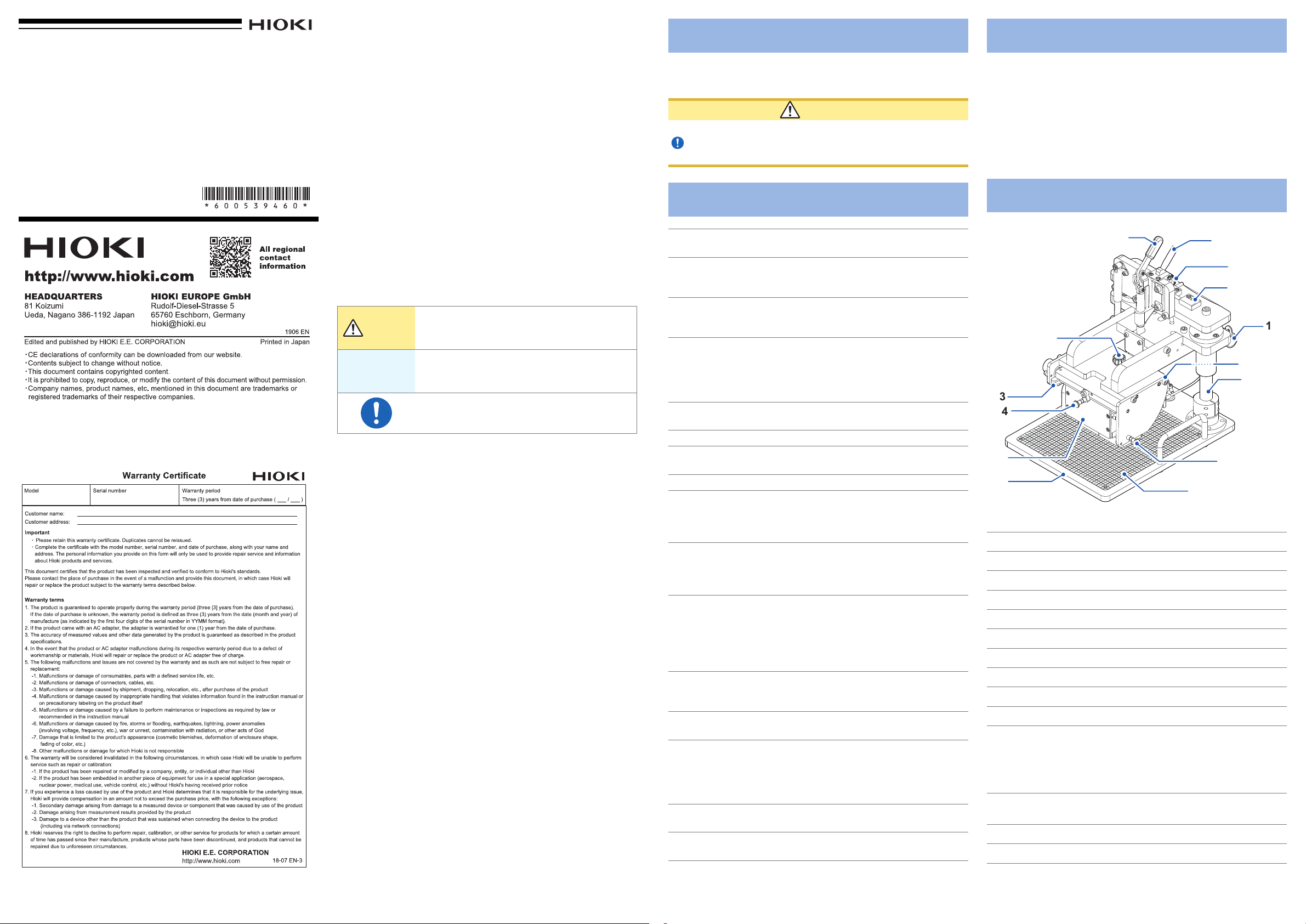
Part Names
1
2
3
4
5
6
Up/down lever
1
Test xture clamp knob
2
Test xture insertion rail
3
Test xture lock lever
4
RM9004 Test Fixture
5
Measurement stage
6
Lock release lever
7
Lock release lever clamp knob
8
Lock disable pin
9
Clamp
10
Serial number
11
(The serial number consists of 9 digits. The rst two [from
the left] indicate the year of manufacture, and the next two
indicate the month of manufacture. Required for product
control. Do not peel off the label.)
Shaft
12
(Do not touch as the shaft is coated with lubricating oil.)
Maintenance plunger
13
Graduated plate
14
7
8
9
10
11
12
13
14
1 2 3 4
Page 2

Assembly (RM9003, RM9004, RM9005)
CAUTION
To avoid equipment damage, turn off the RM2611
Electrode Resistance Meter before connecting or
disconnecting the RM9005 Connection Cable.
IMPORTANT
The device ships with the up/down lever locked with the lock
release lever clamp knob. Loosen the knob before using the
device for the rst time.
Place the RM9003 Press Unit’s up/down lever in the
1
raised position.
Slide the RM9004 Test Fixture into position along
2
the RM9003 Press Unit’s test xture insertion rails.
Push the test xture toward the rear until it won’t go
any further.
Pull the test xture lock lever toward you and
3
downward and then let go to lock.
The RM9004 Test Fixture will lock in place.
Connect the grounding cable on the rear of the
4
RM9003 Press Unit to the ground terminal on the
RM9004 Test Fixture.
Connect the connector on the RM9004 (the female
5
side) and connector on the RM2611 (the male side)
using the RM9005 Connection Cable and screws
that hold it in place.
Secure the RM9005 Connection Cable in place with
6
the cable clamp.
There are screws for attaching the cable clamp on the
left and right sides of the RM9003 Press Unit. Choose
the appropriate side based on the position of the
device.
IMPORTANT
• When connecting the RM9005 Connection Cable, insert the
cable into the connector rmly and tighten it in place with screws.
If the screws loosen, the resulting poor contact could cause a
measurement error.
• Exercise care not to lose the test xture case’s mounting screws,
which you will need in order to store the RM9004 Test Fixture
during transport.
Test xture
insertion rail
RM9004 Test Fixture
Up/down lever
1
RM9003 Press Unit
2
3
Test xture lock lever
Test xture insertion rail
Basic Operation
IMPORTANT
• Exercise caution not to pinch your ngers or other body parts
when lowering the RM9004 Test Fixture.
• Do not touch the tips of the probes when handling the electrode
sheet.
Place an electrode sheet on the measurement stage.
1
The probes will make contact with the bold graduated
marks.
Pull the up/down lever toward you and down while
2
pulling the lock release lever toward you.
The RM9004 Test Fixture will move downward under its
own weight.
Once the RM9004 Test Fixture is fully lowered, start
3
measurement from the main screen of RM2612
Resistance Calculation Software.
See the RM2610 Electrode Resistance Measurement
System Instruction Manual
Once measurement completes, raise the up/down
4
lever.
Remove the electrode sheet from the measurement
5
stage after verifying that the RM9004 Test Fixture is
fully raised.
4
2
Up/down lever
Lock release lever
Precautions when transporting
the device
Be sure to follow these precautions.
• To avoid damage to the device, remove the RM9004 Test
Fixture and RM9005 Connection Cable from the device.
Additionally, use the packaging in which the device was
packed when you purchased it, and be sure to doublebox it. Hioki cannot guarantee that the device will not be
damaged during transport.
• Attach a description of the issue when sending out your
device for repair.
• Raise the up/down lever and then tighten the lock release
lever clamp knob to ensure that the press unit does not
move up or down during transport.
Lock release lever clamp knob
6
Clamp
5
Screw
RM9005
Connection Cable
4
Ground
terminal
Grounding cable
3
5
Measure
PC
1
RM2611 Electrode Resistance Meter
1 2 3 4
 Loading...