

Hioki RM3548 Instruction Manual
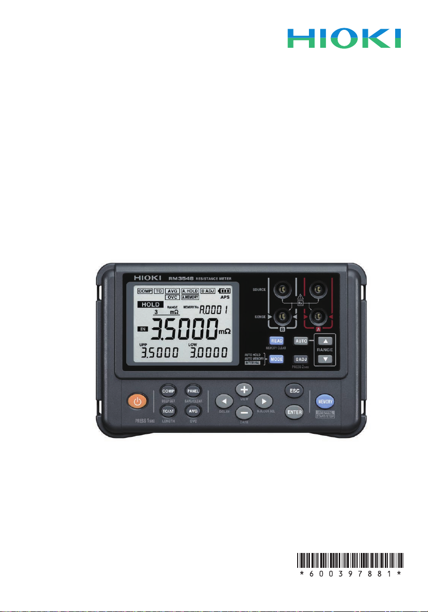
RM3548
Instruction Manual
RESISTANCE METER
May 2015 Revised edition 1
RM3548A981-01 15-05H
EN

How to use the Instruction Manual (this manual)
See below, as appropriate:
Be sure to always read the
following sections.
When you wish to use the
instrument immediately
When you need further information
on the various functions
To nd out about product
specications
If the instrument does not operate
as intended or expected
For detailed information related to
resistance measurement
“Safety Notes” (p. 4)
“Usage Notes” (p. 7)
“Overview” (p. 15)
Refer to the “Contents” (p. i) and/or “Index”
(p. Ind.1) to nd the desired function.
“Specications” (p. 93)
“Troubleshooting” (p. 108)
“Appendix” (p. Appx.1)
1
2
3
4
5
6
7
RM3548A981-01
8
9
10
付録索引


Contents
Introduction ........................................................................................1
Verifying Package Contents .............................................................2
Safety Notes .......................................................................................4
Usage Notes .......................................................................................7
1
1 Overview 15
1.1 Overview and Features .................................................15
1.2 Component Names and Operation Overview .............16
Power-on settings ....................................................................20
1.3 Flow of Measurement ...................................................21
1.4 Screen Layout ...............................................................22
1.5 Checking the Measurement Target .............................25
2 Preparing for Measurement 27
2.1 Attaching the Strap .......................................................28
2.2 Loading or Replacing the Batteries ............................29
2.3 Connecting the Test Leads ..........................................30
2.4 Connecting the Z2002 Temperature Sensor
(When Using TC or ΔT) .................................................31
2.5 Turning the Power On/Off ............................................32
Turning the power on ...............................................................32
Turning the power off ...............................................................32
Automatic power off with auto power save (APS) ....................33
Disabling auto power save (APS) ............................................33
2.6 Pre-measurement Inspection .......................................34
2
3
4
5
6
7
8
3 Basic Measurement 35
3.1 Setting the Measurement Range .................................36
3.2 Connecting the Test Leads to the Measurement
Target .............................................................................38
3.3 Reading the Measured Value .......................................39
Switching the display................................................................39
Verifying measurement errors ..................................................40
Holding a measured value .......................................................42
Memorizing a measured value .................................................42
9
10
Appx. Ind.
i

Contents
4 Customizing Measurement Conditions 43
4.1 Using Zero Adjustment.................................................44
4.2 Stabilizing Measured Values (Averaging Function) ...49
4.3 Compensating for Thermal Effects
(Temperature Correction (TC)) .....................................50
4.4 Compensating for Thermal EMF Offset (Offset
Voltage Compensation Function: OVC Function) ......51
4.5 Setting the Delay Time for Measurement (Delay
Function) ........................................................................53
4.6 Switching the Measurement Current
(In the 300m
Range) ...................................................55
Ω
5 Judgment and Conversion Functions 59
5.1 Judging Measured Values (Comparator Function) ....60
Judging based on upper and lower limit values (ABS mode) ..63
Judging based on a reference value and allowable range
(REF% mode) ..........................................................................64
Verifying a judgment with a sound (judgment sound function) .65
Verifying a judgment on a handheld device
(L2105 LED Comparator Attachment option) ..........................66
5.2 Performing Temperature Rise Test
(Temperature Conversion Function (∆T)) ...................67
5.3 Measuring the Length of a Conductor
(Length Conversion Function) .....................................69
6 Panel Save and Load
(Saving and Loading Measurement
Conditions) 71
6.1 Saving Measurement Conditions
(Panel Save Function) ..................................................72
6.2 Loading Measurement Conditions
(Panel Load Function) ..................................................73
6.3 Clearing the Contents of a Panel .................................74
ii

Contents
7 Memory Function (Saving and Exporting
Measurement Data to a PC) 75
7.1 Saving Data at Specied Time (Manual Memory) ......77
7.2 Saving Data Automatically When Measured
Values Stabilize (Auto-Memory) ..................................78
7.3 Saving Data at Fixed Intervals
(Interval Memory Function) ..........................................79
7.4 Displaying Saved Measurement Data
(Memory Display Function) ..........................................81
7.5 Clearing Measurement Data (Memory Clear) .............82
7.6 Exporting Saved Measurement Data to a PC
(USB Mass Storage Mode) ...........................................86
8 System Settings 89
8.1 Displaying the Date and Time Verication Screen ....89
8.2 Setting the Clock ...........................................................90
8.3 Initializing (Reset) .........................................................91
Default settings ........................................................................92
1
2
3
4
5
6
9 Specications 93
General Specications ....................................................................93
Measurement range .................................................................93
Measurement method ..............................................................93
Measurement specications.....................................................93
Accuracy ..................................................................................96
Functions..................................................................................97
Interface .................................................................................104
Environmental and safety specications ................................105
Accessories ............................................................................105
Options ...................................................................................106
iii
7
8
9
10
Appx. Ind.

Contents
10 Maintenance and Service 107
10.1 Troubleshooting ..........................................................108
Q&A (frequently asked questions and answers) ....................108
Error display and actions........................................................114
10.2 Repair and Inspection ................................................115
10.3 Replacing Fuses .........................................................116
10.4 Disposing of the Instrument ......................................117
Appendix Appx.1
Appx. 1 Block Diagram ...............................................Appx.1
Appx. 2 Four-Terminal (Voltage-Drop) Method .........Appx.2
Appx. 3 DC Method and AC Method ..........................Appx.3
Appx. 4 Temperature Correction Function (TC) .......Appx.4
Appx. 5 Temperature Conversion (ΔT) Function ......Appx.7
Appx. 6 Effect of Thermoelectromotive Force
(Thermal EMF) ................................................Appx.8
Appx. 7 Zero Adjustment ..........................................Appx.11
Appx. 8 Unstable Measurement Values ...................Appx.17
Appx. 9 Locating Short-Circuits on a PC Board .....Appx.27
Appx. 10 Test Lead Options .......................................Appx.28
Appx. 11 Calibration ....................................................Appx.30
Appx. 12 Adjustment ...................................................Appx.33
Index Ind.1
iv

Introduction
Introduction
Thank you for purchasing the HIOKI RM3548 Resistance Meter. To obtain maximum
performance from the product, please read this manual rst, and keep it handy for
future reference.
Registered trademarks
Windows and Excel are registered trademarks of Microsoft Corporation in the United
States and/or other countries.
1
2
3
4
5
6
7
8
9
10
Appx. Ind.
1
Verifying Package Contents
電池
電池
Verifying Package Contents
• When you receive the instrument, inspect it carefully to ensure that no damage
occurred during shipping. In particular, check the accessories, panel switches,
and connectors. If damage is evident, or if it fails to operate according to the
specications, contact your authorized Hioki distributor or reseller.
• When transporting the instrument, use the same packaging materials used for the
delivery to you.
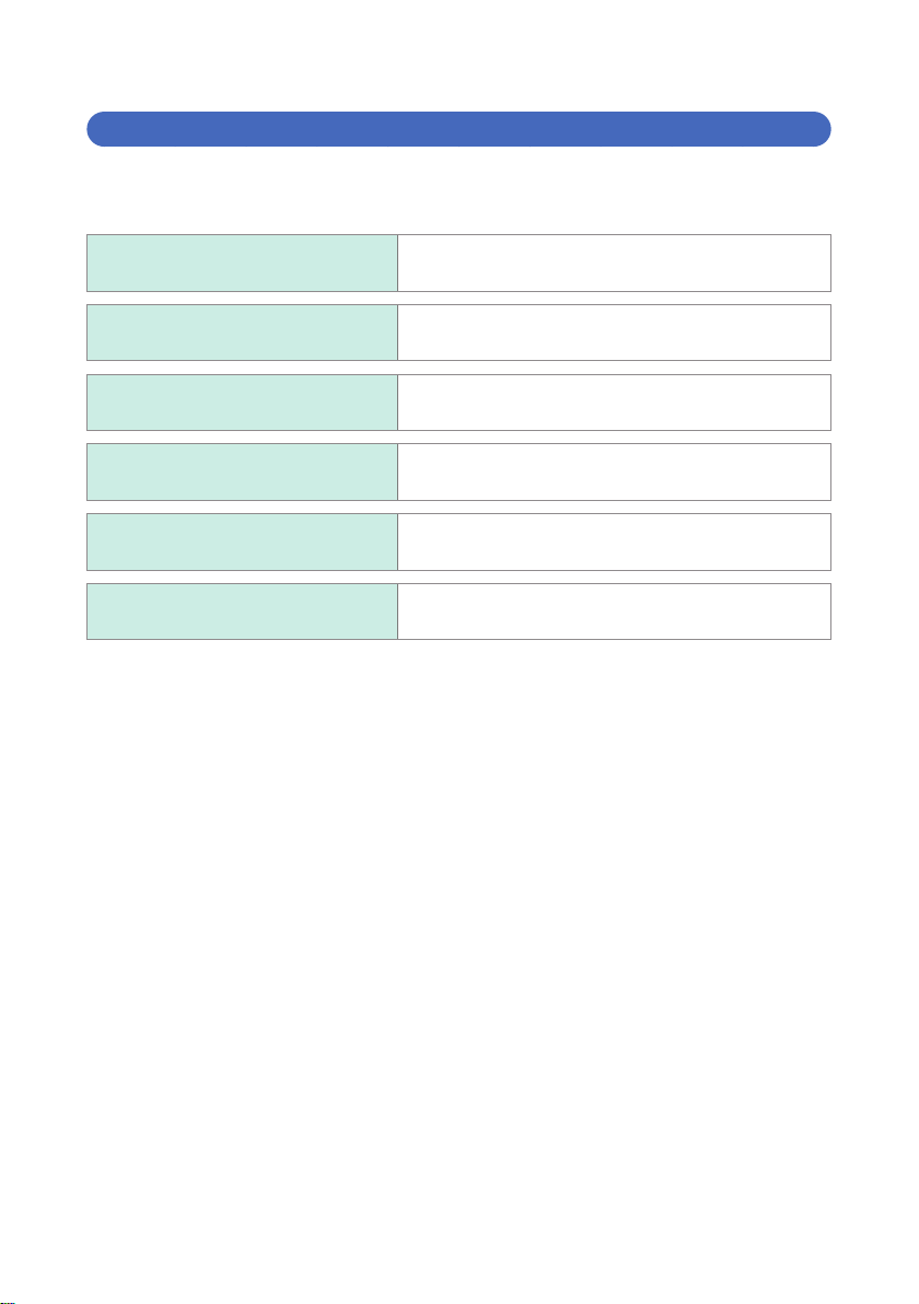
Check the package contents as follows.
RM3548 Resistance Meter Instruction Manual
L2107 Clip Type Lead (p. 30) USB Cable (A-miniB type)
Z2002 Temperature Sensor (p. 31) Strap
LR6 Alkaline battery × 8
2
Spare fuse (F2AH/250 V)
Verifying Package Contents
JAPAN
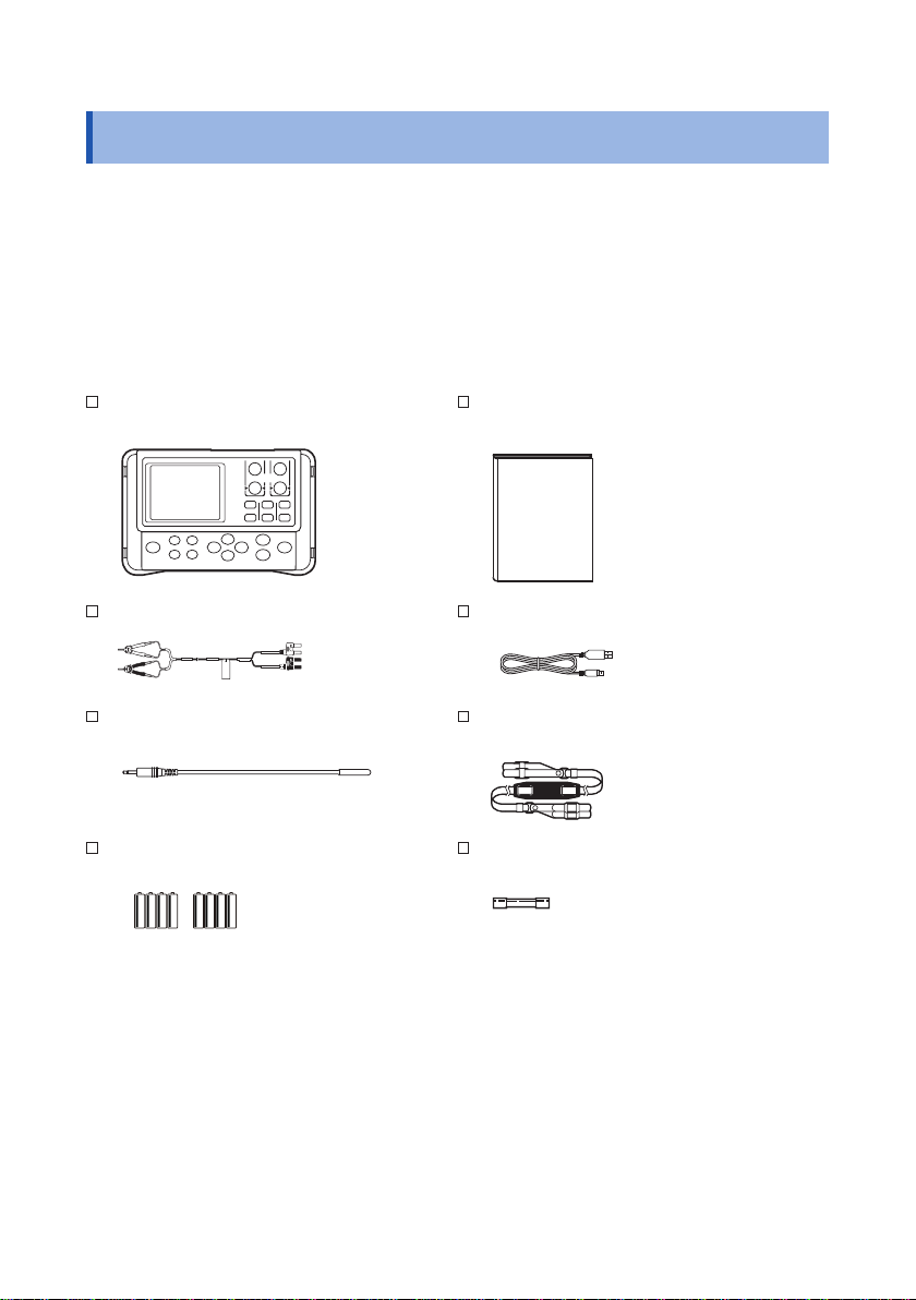
Options
For details, contact your authorized Hioki distributor or reseller. (p. Appx.28)
L2107 Clip Type Lead 9467 Large Clip Type Lead
9453 Four-Terminal Lead 9772 Pin Type Lead
9465-10 Pin Type Lead 9454 Zero Adjustment Board
Z2002 Temperature Sensor L2105 LED Comparator Attachment
C1006 Carrying Case
1
2
3
4
5
6
7
8
9
10
Appx. Ind.
3
Safety Notes
Safety Notes
The instrument is designed to conform to IEC 61010 Safety Standards, and has been
thoroughly tested for safety prior to shipment. However, using the instrument in a way
not described in this manual may negate the provided safety features.
Before using the instrument, be certain to carefully read the following safety notes.
DANGER
Mishandling during use could result in injury or death, as well
as damage to the instrument. Be certain that you understand the
instructions and precautions in the manual before use.
WARNING
With regard to the electricity supply, there are risks of electric shock,
heat generation, re, and arc discharge due to short circuits. If
persons unfamiliar with electricity measuring instruments are to use
the instrument, another person familiar with such instruments must
supervise operations.
This manual contains information and warnings essential for safe operation of
the instrument and for maintaining it in safe operating condition. Before using the
instrument, be certain to carefully read the following safety notes.
4

Safety Notes
Notation
In this manual, the risk seriousness and the hazard levels are classied as follows.
DANGER
WARNING
CAUTION
IMPORTANT
Indicates an imminently hazardous situation that will result in death or
serious injury to the operator.
Indicates a potentially hazardous situation that may result in death or
serious injury to the operator.
Indicates a potentially hazardous situation that may result in minor
or moderate injury to the operator or damage to the instrument or
malfunction.
Indicates information related to the operation of the instrument or
maintenance tasks with which the operators must be fully familiar.
Indicates prohibited actions.
Indicates the action which must be performed.
1
2
3
4
*
p. Indicates the location of reference information.
[ ] An item enclosed by [ ] indicates a key name.
Unless otherwise noted, Windows XP, Windows Vista, Windows 7, and Windows 8 are
referred to as “Windows”.
Additional information is presented below.
5
6
7
8
9
10
Appx. Ind.
5
Safety Notes
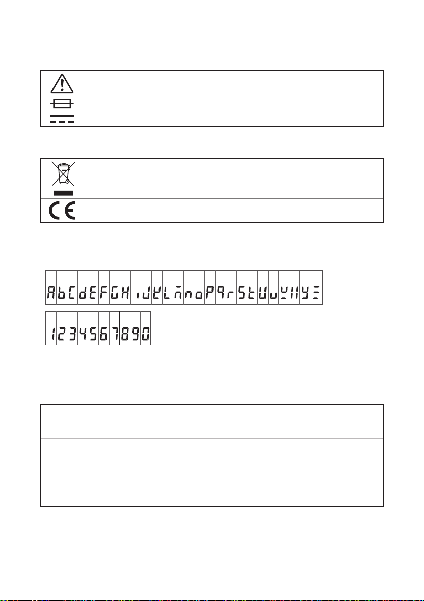
Symbols afxed to the instrument
Indicates cautions and hazards. When the symbol is printed on the instrument,
refer to a corresponding topic in the Instruction Manual.
Indicates a fuse.
Indicates DC (Direct Current).
Symbols for various standards
Indicates the Waste Electrical and Electronic Equipment Directive (WEEE
Directive) in EU member states.
Indicates that the instrument conforms to regulations set out by the EC Directive.
Screen display
The instrument uses the following screen displays.
A B C D E F G H I J K L M N O P Q R S T U V W X Y Z
1 2 3 4 5 6 7 8 9 0
Accuracy
We dene measurement tolerances in terms of f.s. (full scale), rdg. (reading) and dgt.
(digit) values, with the following meanings:
(Maximum display value)
f.s.
rdg.
dgt.
This is usually the maximum display value. In the instrument, this indicates the
currently used range.
(Reading or displayed value)
The value currently being measured and indicated on the measuring
instrument.
(Resolution)
The smallest displayable unit on a digital measuring instrument, i.e., the input
value that causes the digital display to show a “1”.
See: “Accuracy calculation examples” (p. 96)
6
Usage Notes
Usage Notes
Follow these precautions to ensure safe operation and to obtain the full benets of
the various functions.
Checking before use
Before using the instrument the rst time, verify that it operates normally to ensure
that no damage occurred during storage or shipping. If you nd any damage, contact
your authorized Hioki distributor or reseller.
DANGER
Before using the instrument, check that the coating of the test leads
or cables are neither ripped nor torn and that no metal parts are
exposed. Using the instrument under such conditions could result
in electrocution. Replace the test leads with those specied by our
company.
Installation
Installation environment
Operating temperature
and humidity ranges
Storage temperature
and humidity ranges
Installing the instrument in inappropriate locations may cause a malfunction of
instrument or may give rise to an accident. Avoid the following locations.
0°C to 40°C 80%RH or less (no condensation)
-10°C to 50°C 80%RH or less (no condensation)
1
2
3
4
5
6
7
CAUTION
• Exposed to direct sunlight or high temperature
• Exposed to corrosive or combustible gases
• Exposed to water, oil, chemicals, or solvents
• Exposed to high humidity or condensation
• Exposed to a strong electromagnetic eld or electrostatic charge
• Exposed to high quantities of dust particles
• Near induction heating systems (such as high-frequency induction
heating systems and IH cooking equipment)
• Susceptible to vibration
8
9
10
Appx. Ind.
7
Usage Notes
IMPORTANT
Accurate measurement may be impossible in the presence of strong magnetic
elds, such as near transformers and high-current conductors, or in the presence of
strong electromagnetic elds such as near radio transmitters.
Handling precautions
WARNING
• Do not allow the instrument to get wet, and do not use it with wet
hands. This may cause electric shock accident.
• Do not modify, disassemble, or repair the instrument. This may
result in re, electric shock accident, or injury.
CAUTION
• Do not place the instrument on an unstable or slanted surface. It may
drop or fall, causing injury or instrument failure.
• To avoid any damage to the instrument, avoid any vibration or shock
during transport or handling. Especially, be careful not to drop or fall the
instrument which will cause shock.
• To avoid any damage to the instrument, do not input voltage or current to
any measurement, TEMP.SENSOR, or COMP.OUT terminals.
Precautions during shipment
Observe the following during shipment.
Hioki cannot be responsible for damage that occurs during shipment.
CAUTION
• During shipment of the instrument, handle it carefully so that it is not
damaged due to a vibration or shock.
• To avoid damage to the instrument, remove the accessories and optional
equipment from the instrument during shipment.
If the instrument is not used for an extended period of time
IMPORTANT
To avoid corrosion and/or damage to the instrument due to battery leakage, remove
the batteries from the instrument if it is to be kept in storage for an extended period.
8
Handling leads and cables
Usage Notes
DANGER
To avoid electrical shock accident, do not short test leads where
voltage is applied.
CAUTION
• Avoid stepping on or pinching the leads, which could damage the lead
insulation.
• To avoid damaging the cables, do not bend or pull the base of cables and
the leads.
• When removing a connector, hold its plug portion, not its cable, to prevent
a wire disconnection.
• The ends of pin type leads are sharp. Be careful to avoid injury.
• Melted lead wire is dangerous because its metal part is exposed.
Be careful not to allow contact between the lead wire and the heat
generating portion.
• The Z2002 Temperature Sensor is precision-machined. Excessively high
voltage pulses or static electricity may damage the sensor.
• Do not apply an excessive impact to the tip of the Z2002 Temperature
Sensor or bent the lead wire. It may cause failure or wire disconnection.
IMPORTANT
• Do not use any test lead or temperature sensor other than the ones specied by
our company. It may result in inaccurate measurement due to poor contact or
other reasons.
• If the jack of a test lead or the temperature sensor is dirty, wipe it off. Otherwise,
the contact resistance will increase, affecting the temperature measurement.
• Be careful so that the temperature sensor connector does not come off. (The
temperature correction or conversion function will not work if the connector
comes off.)
1
2
3
4
5
6
7
8
9
Before attaching the strap
Use the four attachment points on the instrument to attach the strap
securely. Otherwise, the instrument may drop during carrying, damaging
the instrument.
CAUTION
10
Appx. Ind.
9
Usage Notes
Batteries
Poor performance or damage from battery leakage could result.
Observe the cautions listed below.
WARNING
• Do not short circuit, charge, disassemble, or incinerate batteries. Doing
so may cause an explosion and is dangerous.
• To avoid electric shock accident, remove any test leads before replacing
batteries.
• After the replacement, be sure to reattach the cover.
CAUTION
• Do not use both new and old batteries or different types of batteries
together.
• Be careful to observe battery polarity. Otherwise, poor performance or
damage from battery leakage could result.
• Do not use batteries after their recommended expiry date.
• Do not allow used batteries to remain in the instrument.
• To avoid corrosion and/or damage to the instrument due to battery
leakage, remove the batteries from the instrument if it is to be kept in
storage for an extended period.
IMPORTANT
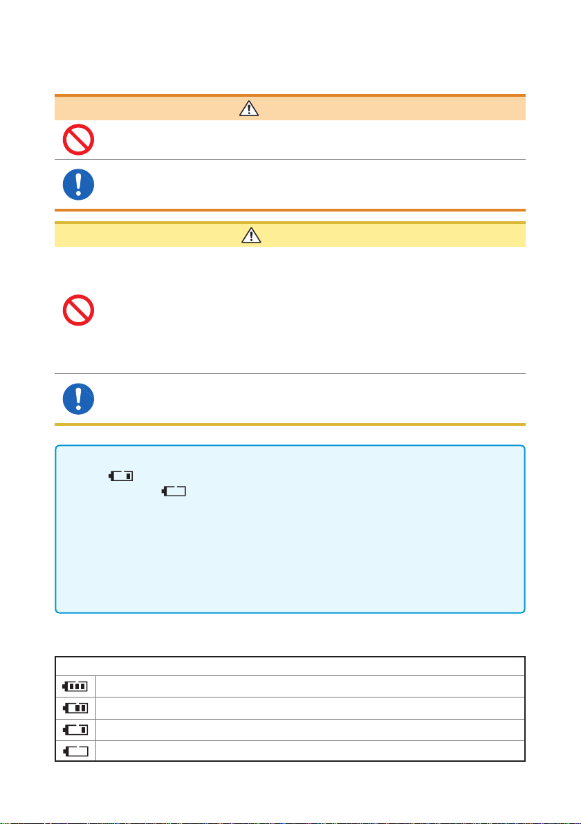
• When
possible. When
Replace the batteries.
• Be sure to turn the power off after using it.
• In this manual, the “batteries” are those used to power the instrument.
• Do not use any batteries other than the specied type (LR6 alkaline batteries).
Ni-MH batteries may cause battery leakage, depending on the degree of battery
charge and deterioration.
• Dispose of batteries in accordance with local regulations.
is lit, the battery becomes low. Replace the batteries as soon as
is blinking, the battery becomes too low for measurement.
Remaining battery level indicator
Indication
The battery is fully charged.
As the remaining amount of batteries becomes low, the bars disappear from the left.
The battery becomes low. Replace the batteries as soon as possible.
(Blinking) There is no battery remaining. Replace the batteries with new ones.
10
Before connecting test leads
Usage Notes
DANGER
To avoid electric shock or short-circuit accident, turn any
measurement target off before connecting test leads.
Before connecting the L2105 LED Comparator Attachment
CAUTION
• To prevent the instrument and the L2105 LED Comparator Attachment
from breaking down, turn the power off before connecting the L2105 LED
Comparator Attachment.
• The COMP.OUT terminal is for the L2105 only. Do not connect any
terminal other than the L2105.
• Connect the temperature sensor securely. Otherwise, the specications
may not be met.
• When a tie band is used, do not tighten the test lead excessively.
It could damage the test lead.
• Do not perform the following as they could damage the core or coating of
a cable.
Twisting or pulling the cable
Connecting the cable around the L2105 LED Comparator Attachment
by bending it compactly
Before connecting the Z2002 Temperature Sensor
1
2
3
4
5
6
7
WARNING
Connect the Z2002 Temperature Sensor securely. Otherwise,
specications may not be met or a failure may occur.
CAUTION
• To prevent the instrument and the Z2002 Temperature Sensor from
breaking down, turn the power off before connecting the Z2002
Temperature Sensor.
• Insert the Z2002 Temperature Sensor all the way into the TEMP.SENSOR
terminal. Otherwise, the measurement may have a large error.
IMPORTANT
If the jack of the Z2002 Temperature Sensor is dirty, wipe it off. Otherwise, the
temperature measurement may have an error.
8
9
10
Appx. Ind.
11
Usage Notes
Measurement precautions
To avoid electrical shock accident, do not short test leads where
voltage is applied.
• To prevent electric shock accident
or damage to the instrument, do not
apply voltage to any measurement
terminal. To avoid electrical accident,
remove power from the measurement
target before measurement.
• Electrical sparks may occur at the moment of connecting/disconnecting
the power cable to/from the measurement target. Do not use the
instrument where combustible gases are generated.
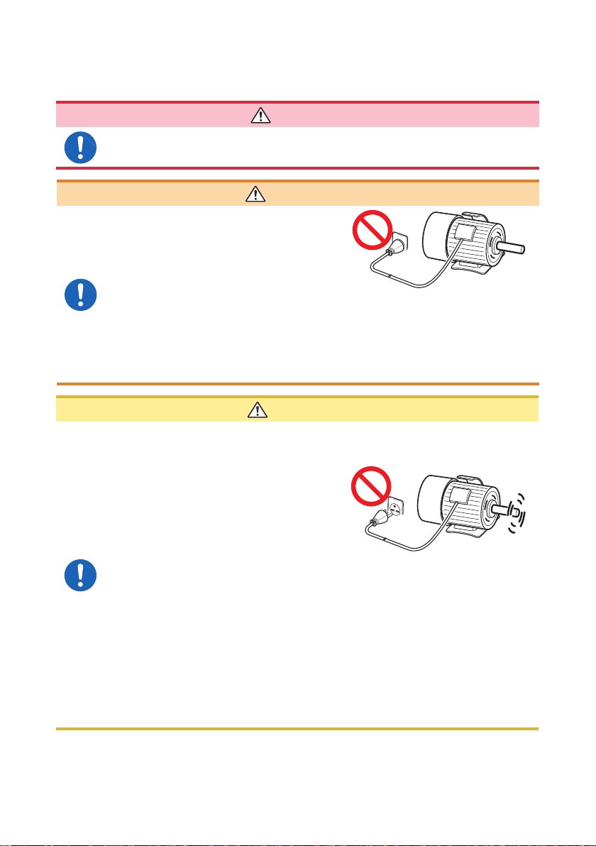
• Do not measure a point where
voltage is applied. When a motor
is turned off, the motor does not
stop immediately and is rotating
inertially. And, in such a state, a
large electromotive force is still being
generated.
If a transformer or motor is measured
immediately after a voltage withstand
test, the instrument will be damaged
due to induced voltage or residual
charge.
• When measuring a transformer or coil with an inductance of 5 H or more
and with a resistance of 1
in which a measurement current of 1 A ows. The instrument may be
damaged.
• Do not attempt to measure the internal resistance of a battery. The
instrument will be damaged. To measure internal resistance of a battery,
use a HIOKI 3554, 3555, BT3562, BT3563, or 3561 Battery HiTESTER.
DANGER
WARNING
The measurement target is connected
to power.
CAUTION
Rotating inertially
or less, do not use the 3mΩ or 30mΩ range
Ω
12
Usage Notes
IMPORTANT
• The SOURCE terminals are protected with a fuse. If the fuse is broken, “FUSE”
appears, and resistance cannot be measured. In such a case, replace the fuse.
(p. 116)
• Since the instrument uses DC current for measurement, it may be affected by
thermal EMF (thermoelectromotive force), resulting in a measurement error. If so,
use the Offset Voltage Compensation function.
“4.4 Compensating for Thermal EMF Offset (Offset Voltage Compensation
Function: OVC Function)” (p. 51)
“Appx. 6 Effect of Thermoelectromotive Force (Thermal EMF)” (p. Appx.8)
• When a power transformer or open solenoid coil with a high inductance, or the
like is measured, the measured value may not stabilize. If so, connect a lm
capacitor of 1 µF or so between the SOURCE A and B terminals.
• Ensure that the SOURCE-A, SENSE-A, SENSE-B, and SOURCE-B terminal
connections are isolated from each other. If a core or shield wire touches
another, the instrument will become unable to perform accurate four-terminal
measurement, resulting in a measurement error.
1
2
3
4
Using the Z2002 Temperature Sensor
CAUTION
The Z2002 Temperature Sensor does not have a waterproof construction.
Do not put the sensor into water or any other liquid.
IMPORTANT
• When using the temperature correction function, wait until the measurement
target and Z2002 Temperature Sensor come close enough to ambient
temperature for the measurement. Otherwise, it may result in a large
measurement error.
• Do not hold the Z2002 Temperature Sensor with a bare hand. It may cause
enough noise pickup to destabilize the measurement.
• The Z2002 Temperature Sensor is designed for ambient temperature
measurement. The temperature of a measurement target cannot be measured
correctly even if the Z2002 Temperature Sensor is attached to its surface or other
portion.
• Insert the Z2002 Temperature Sensor all the way into the TEMP.SENSOR
terminal. Otherwise, the measurement may have a large error.
5
6
7
8
9
10
Appx. Ind.
13

Usage Notes
14
1
Overview
1.1 Overview and Features
The Hioki RM3548 employs the four-terminal method to highly accurately measure
the DC resistance of measurement targets including motor and transformer windings,
and welding, PC board patterns, fuses, resistors, and materials such as conductive
rubber. The instrument allows temperature correction and so is especially suitable for
measurement targets whose resistance values change with temperature.
Highly reliable specications implemented in a compact, light-weight body
• 35,000-dgt. high resolution
• 0.1µΩ resolution at 1 A measurement current
Neither a warm-up time nor zero adjustment is required before starting
measurement
Simple temperature rise test (for temperature estimation during power stop)
• Temperature conversion and interval measurement functions
• Supports copying of measurement data le from the instrument memory to the PC
Well-designed instrument shaped for measuring without taking your hands
and eyes off the target, making it ideal for maintenance and large product
measurement
• Strap-attachable portable type
• Standard auto-memory and auto-hold, and optional L2105 LED Comparator Attachment
1
2
3
4
5
6
7
15
8
9
10
Appx. Ind.
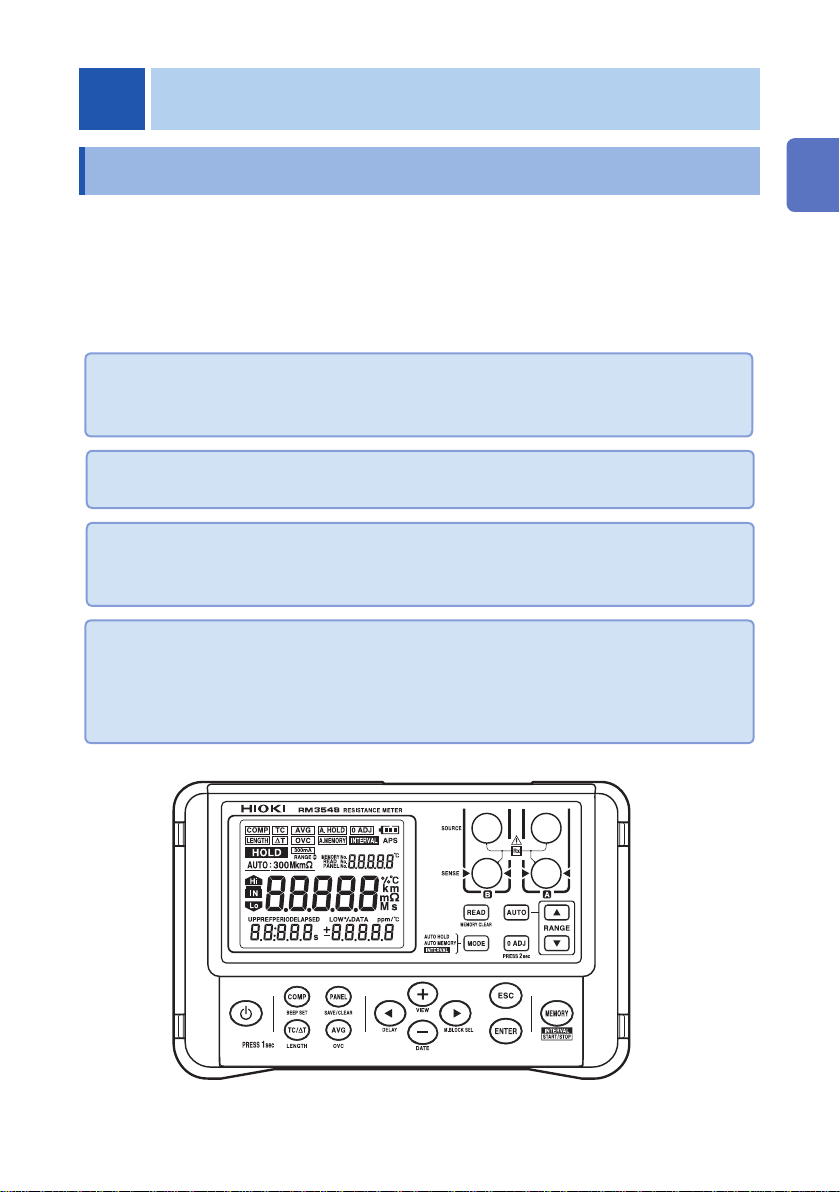
Component Names and Operation Overview
1.2 Component Names and Operation Overview
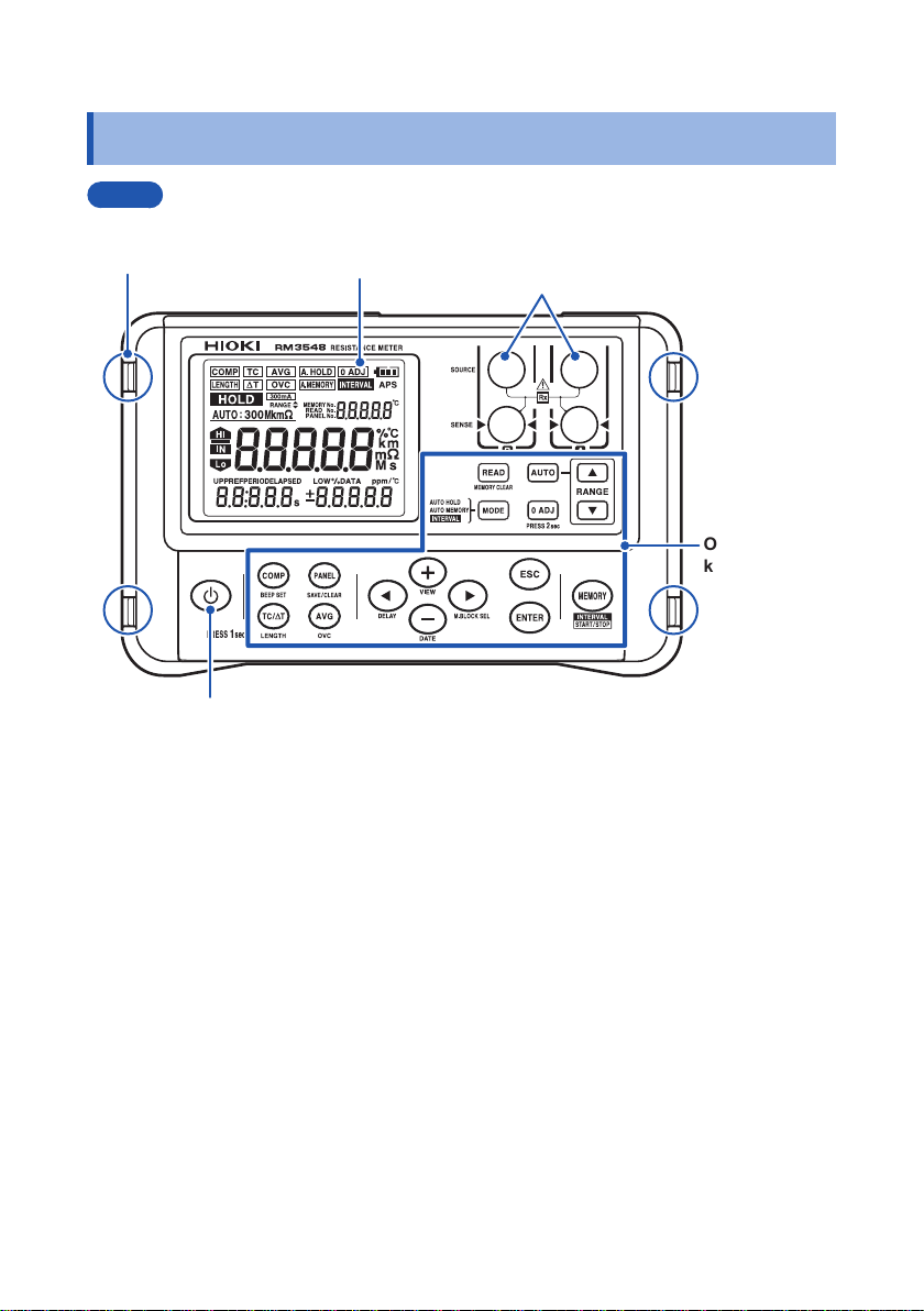
Front
Strap attachment
holes (four) (p. 28)
[POWER] key
Turns the power on/off. (p. 32)
Display (p. 22)
Measurement
terminals (p. 30)
Operation
keys (p. 18)
16
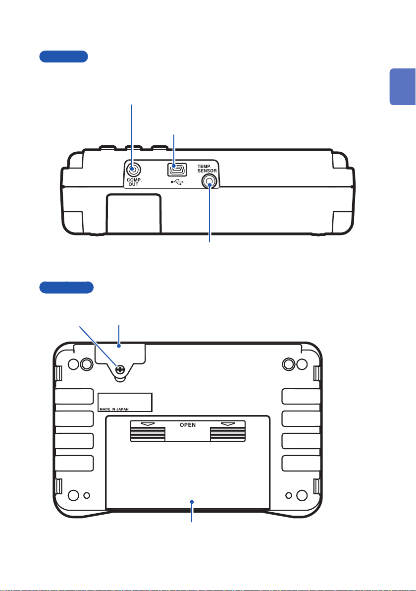
Top view
Component Names and Operation Overview
COMP. OUT terminal
Connect an optional L2105 LED Comparator
Attachment. (p. 66)
USB terminal
Connect a USB cable. (p. 86)
1
2
3
4
Back view
Set screw
TEMP.SENSOR terminal
Connect the included Z2002 Temperature Sensor.
(p. 31)
Fuse cover
Contains a fuse for measurement circuit protection. (p. 116)
Battery cover
Contains eight LR6 alkaline batteries. (p. 29)
5
6
7
8
9
10
Appx. Ind.
17
Component Names and Operation Overview
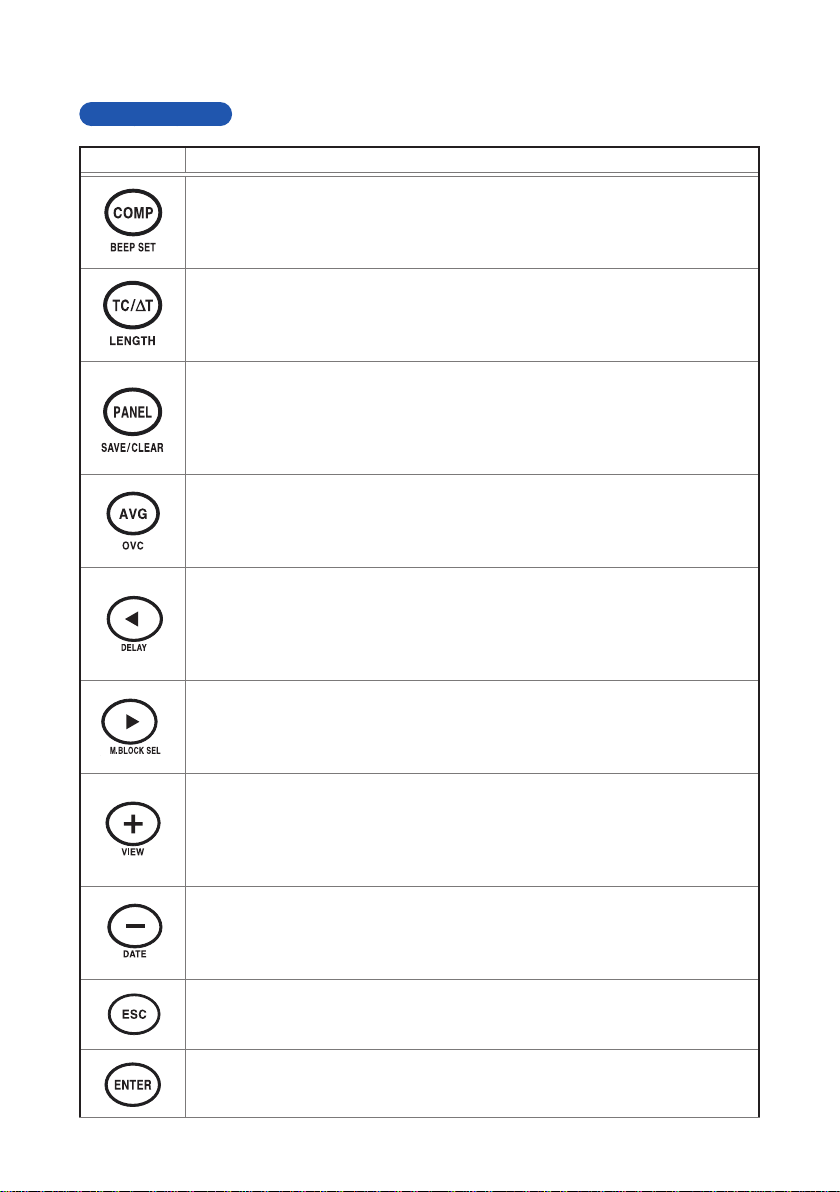
Operation keys
Key Description
[COMP] key (p. 62)
• Comparator: oFF → ON (ABS mode) → ON (REF% mode)
[BEEPSET] key (press and hold) (p. 65)
• Judgment sound: oFF → Hi → in → Lo → Hi-Lo → ALL1 → ALL2
[TC/∆T] key (p. 50) (p. 67)
• Temperature correction/conversion function: oFF → TC → ΔT
[LENGTH] key (press and hold) (p. 69)
• Length conversion function: oFF → ON
[PANEL] key (p. 73)
• Panel load: Changes the panel No. “PrSEt” initializes the measurement
conditions.
[SAVE/CLEAR] key (press and hold) (p. 72, p. 74)
• Saves and clears panels: SAvE → CLr
[AVG] key (p. 49)
• Averaging function: oFF → 2 → 5 → 10 → 20
[OVC] key (press and hold) (p. 51)
• Offset voltage compensation (OVC) function: oFF → oN
[] key
• Moves to a different digit of the setting
[DELAY] key (press and hold) (p. 53)
• Delay function: PrSEt (factory default) → 10 ms → 30 ms → 50 ms →
100 ms → 300 ms → 500 ms → 1000 ms
[] key
• Moves to a different digit of the setting
[M.BLOCK SEL] key (press and hold) (p. 76)
• Selects a memory block: A → b → C → d → E → F → G → H → J → L
[+] key
• Changes values and items
[VIEW] key (press and hold) (p. 39)
• Toggles the display: Temperature → no indicator → memory number
(MEMORY No.)
[−] key
• Changes values and items
[DATE] key (press and hold) (p. 89)
• Displays the date and time conrmation screen.
[ESC] key
• Cancels the setting (when in the setting screen)
• Releases a HOLD state (if in a HOLD state)
18
[ENTER] key
Applies the setting
Component Names and Operation Overview
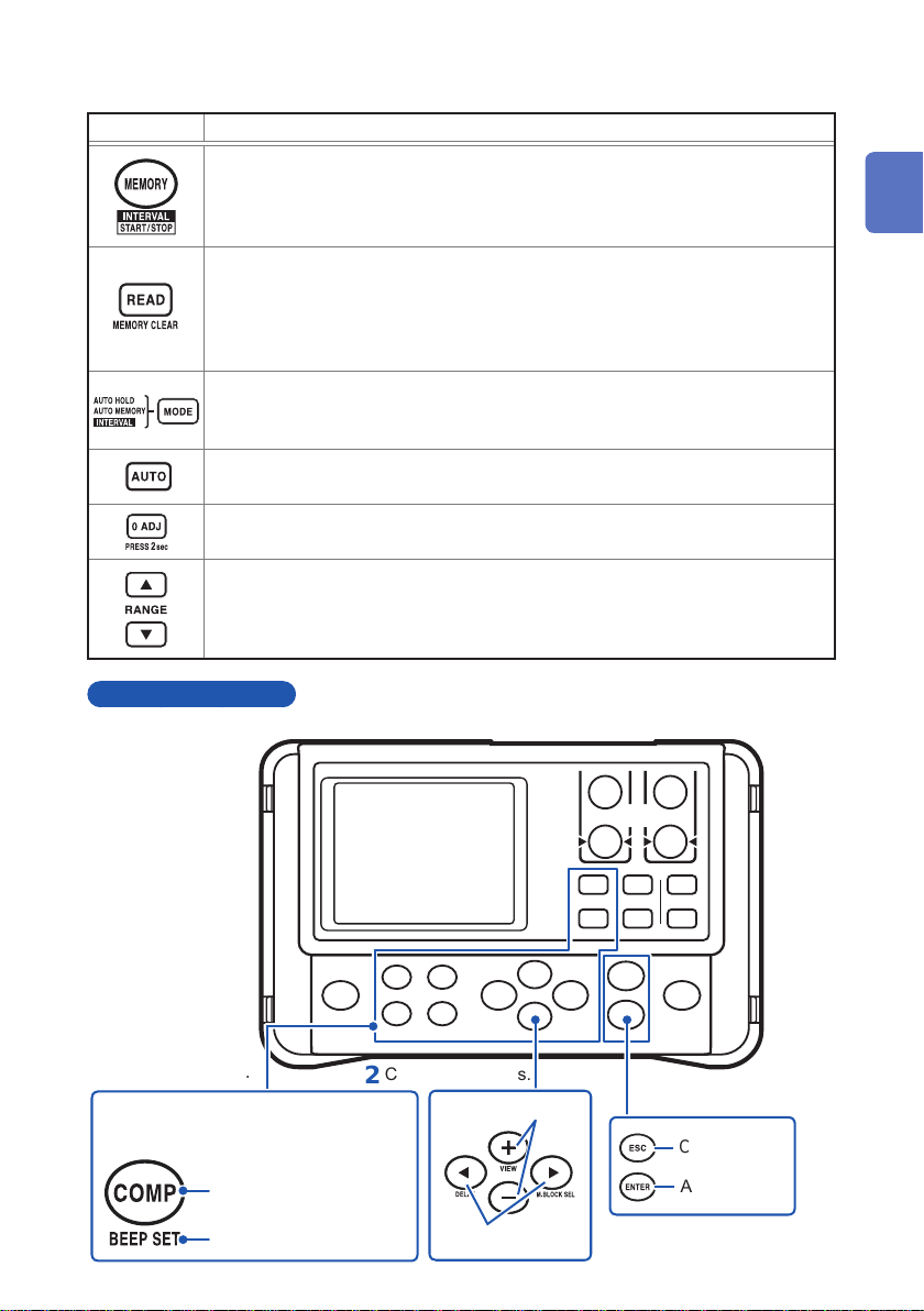
Key Description
[MEMORY] key (p. 77)
• Saves the measured values (manual memory)
[START/STOP] key (press and hold) (p. 79)
• Starts/stops interval measurement (when in interval mode)
[READ] key (p. 81)
• Displays saved measurement data
[MEMORY CLEAR] key (press and hold) (p. 82)
• Clears memory: LASt (Latest data from the selected block) → bLoC (Selected
block) → ALL (All data)
[MODE] key (p. 42, p. 78, p. 79)
Switches memory hold mode: oFF → A.HOLD (auto-hold)
→ A.HOLD,A.MEMORY (auto-memory) → INTERVAL (interval function)
[AUTO] key (p. 37)
Turns on/off the auto range: AUTO lit → not lit
[0 ADJ] key (press and hold) (p. 44)
Zero adjustment
[RANGE] key (p. 36)
Measurement range:
3m
↔ 30mΩ ↔ 300mΩ ↔ 3Ω ↔ 30Ω ↔ 300Ω ↔ 3kΩ ↔ 30kΩ ↔ 300kΩ ↔
Ω
3M
Ω
Operation overview
1
2
3
4
5
6
Select a function.
1
The function shown below each key can be
selected by pressing and holding the key.
Name of the key that turns ON
when it is pressed
Name of the key that turns ON
when it is pressed and held
Congure settings.
2
Changes items/values.
Moves digits.
Apply settings.
3
Cancel
Apply
7
8
9
10
Appx. Ind.
19
Component Names and Operation Overview
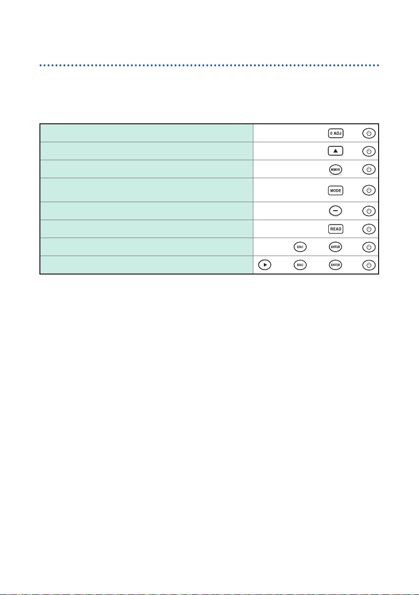
Power-on settings
To perform one of the following settings, it is necessary to turn the power from off to
on while holding-down a particular key.
For details, see the indicated page.
Clearing zero adjustment (p. 48)
Switching to a different measurement current (p. 55)
Disabling auto power save (APS) (p. 33)
Changing the decimal point character or delimiter
character for a CSV le (p. 88)
Setting the date and time (p. 90)
Clearing all measurement data saved (p. 85)
Resetting the current measurement conditions (p. 91)
Resetting the system (p. 91)
+
+
+
+
+
+
+ +
+ + +
20
1.3 Flow of Measurement
Flow of Measurement
Before using the instrument, be sure to see “Usage Notes” (p. 7).
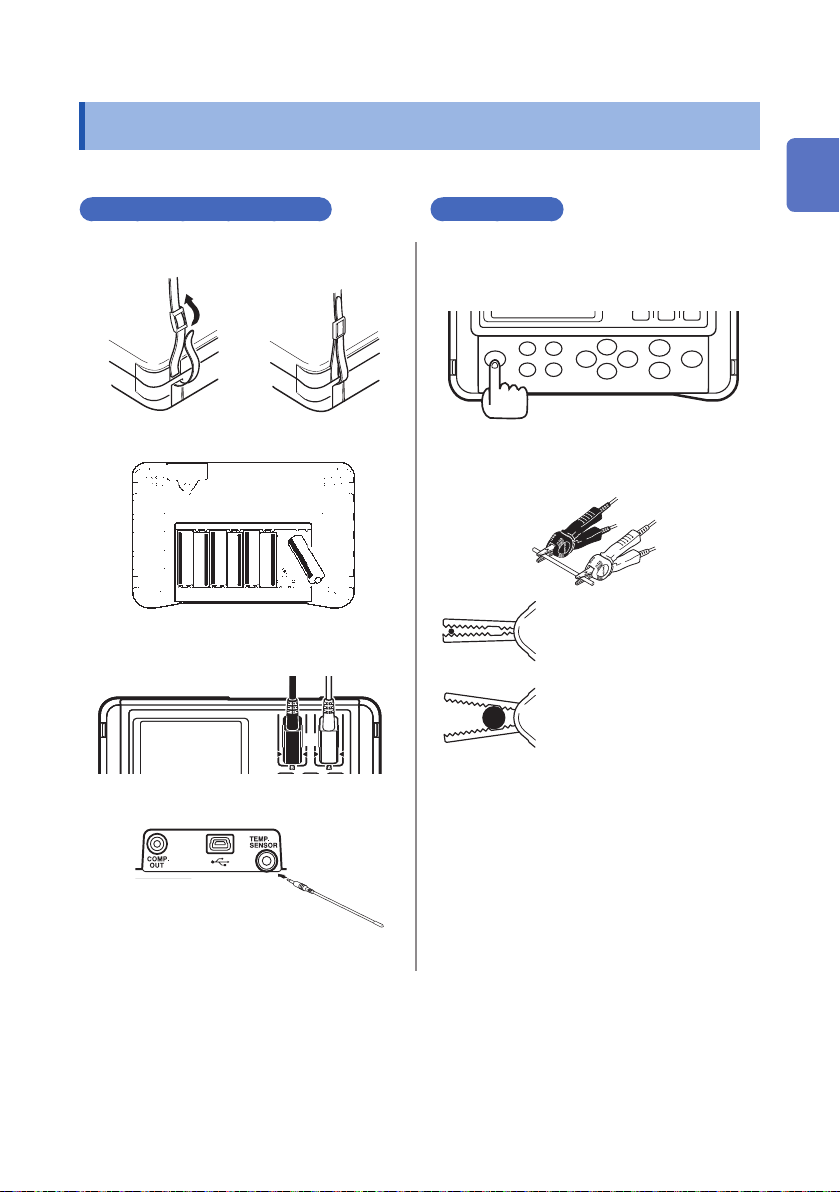
Preparing for measurement
Attach the strap. (p. 28)
1
Load or replace the batteries. (
2
Connect the test leads. (p. 30)
3
Connect a Z2002 Temperature
4
Sensor. (p. 31)
p. 29
Measurement
1
)
2
3
4
Turn the power on and congure
settings.* (p. 32)
Connect the test leads to the
measurement target. (p. 38)
Clipping a thin wire (with
the edge portion of the
jaws)
Clipping a thick wire
(with the base, nonserrated portion of the
jaws)
Read the measured value. (p. 39)
Remove the test leads from the
measurement target and turn the
power off. (p. 32)
1
2
3
4
5
6
7
8
9
* In the following cases, perform zero adjustment:
The display is not cleared due to thermal EMF or other factors. → The display will be changed
to zero.
(Accuracy is not affected by whether or not the zero adjustment is performed.)
Thermal EMF can also be canceled by using OVC. (p. 51)
Four-terminal connection (called Kelvin connection) is difcult.
→ The residual resistance of the two-terminal connection wires will be canceled.
For zero adjustment procedures, see (p. Appx.11).
10
Appx. Ind.
21
Screen Layout
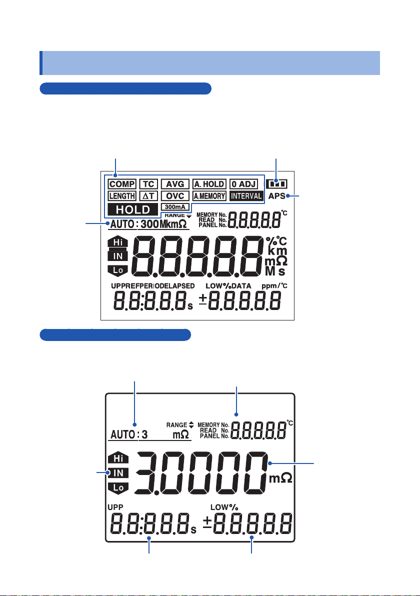
1.4 Screen Layout
Display (when the entire display is lit)
Displays measurement conditions, settings, measured values, memory numbers
(MEMORY No.), panel numbers, comparator settings, judgment results, etc. For
information on the error display, see “Error display and actions” (p. 114).
Remaining battery
Indicators (p. 24)
Range
indicator
indicator (p. 10)
APS indicator
(p. 33)
Resistance measurement screen
Range (p. 36)
Comparator
judgment
result
(p. 60)
22
Using the [VIEW] key to switch the indicator
display (p. 39)
(Temperature, no indicator, memory number
(MEMORY No.))
Measured
value (p. 39)
Comparator lower limit (p. 60)Comparator upper limit (p. 60)
 Loading...