

Page 1

Instruction Manual
RM3545
RM3545-01
RM3545-02
RESISTANCE METER
October 2013 Revised edition 1 RM3545A981-01 13-10H
Page 2

Page 3
Using This Instruction Manual
To do this… Refer to these sections in t his m anual.
Review important
information
Start using the instrument right away
Learn more about
instrument functions
Learn more about
product specifications
Troubleshoot a problem
Learn more about
resist ance measure ment
Learn more about
communicat i o ns commands
Safety Informati o n (p.4)
Operating Precautions (p.6)
Overview (p.19)
Search for the function in question in the table
of contents (p.i) or the index (p.Index 1).
Specifications (p. 251)
Troubleshooting (p. 286)
Appendix (p . A1)
Communications Command Instruction Manual
(on the application di sc)
Page 4

Page 5

Contents
Introduction.....................................................1
Verifying Package Contents...........................2
Safety Information..........................................4
Operating Precautions......... ..... ...... ..... ...........6
Chapter 1 Overview 19
1.1 Product Overview and Features ........19
1.2 Names and Functions of Parts ...........22
1.3 Measurement Process .......................25
1.4 Screen Organization and
Operation Overview ...........................27
1.5 Checking the Measurement Target ....33
Chapter 2 Measurement
Preparations 35
2.1 Connecting the Power Cord............... 35
2.2 Connecting Measurement Leads .......36
2.3 Connecting Z2001 Temperature Sensor
or Thermometer with Analog Output
(When using the TC or T) ................37
Connecting the Z2001 Temperature Sensor
...................................................................37
Conn ect i ng an Anal o g Outp ut Th er mo meter
...................................................................39
2.4 Installing the Multiplexer Unit .............42
2.5 Turning the Power On and Off ...........43
Turning On the Instrument with the
Main Power Switch ...................................43
Turning Off the Instrument with the
Main Power Switch ...................................43
Canceling the Standby State ....................43
Placing the Instrument in the Standby State
......................... ....................... .................. 44
2.6 Pre-Operation Inspection ...................45
Chapter 3 Basic Measurements
47
3.1 Checking the Measurement Target ....48
3.2 Selecting the Measurement Range ....49
Contents
3.3 Setting the Measurement Speed ........50
3.4 Connecting Measurement Leads to the
Measurement Target ..........................51
3.5 Checking Measured Values ...............52
Switching the Display ............................... 52
Confirming Measurement Faults .............. 55
Holding Measured Values ........................ 60
Chapter 4 Cu stom iz ing
Measurement
Conditions 63
4.1 Switching to Low-power Resi stance
Measurement .....................................64
4.2 Switching Measurem en t Curre nts
(100 m to 100 ) ..............................66
4.3 Zero Adjustment .................................68
4.4 Stabilizing Measured Values
(Averaging Function) ..........................73
4.5 Correcting for the Effect s of Temper atur e
(Temperatu re Correction (TC)) ...........75
4.6 Correcting Measured Values and
Displaying Physical Properties Other
than Resistance Values
(Scaling Function) ..............................77
4.7 Changing the Number of Measured
Value Digits ........................................81
4.8 Compensating for Thermal EMF Of fset
(Offset Voltage Compensation - OVC)
...........................................................82
4.9 Setting Pre-Measurement Delay ........84
4.10 Checking for Poor or Improper Contact
(Contact Check Function) ...................88
4.11 Improving Probe Contact
(Contact Improver Function) ...............90
4.12 Maintaining Measurement Precision
(Self-Calibration) ................................92
4.13 Increasing the Precision of the 100 M
Range (100 M High-precision Mode)
...........................................................96
i
1
2
3
4
Page 6

ii
Contents
Chapter 5 Judgment, Statistics,
and Conversion
Functions 97
5.1 Judging Measured Valu es
(Comparator Function) .......................98
Enabling and Disabli ng the Compa ra t or
Function ................ ................................. 100
Decide According to Upper/Lower
Thresholds (ABS Mode) .................... ..... 101
Decide According to Reference Value and
Tolerance (REF% Mode) ....................... 103
Checking Judgments Using Sound
(Judgment Sound Setting Function) ...... 105
Checking Judgments with the L2105 LED
Comparator Attachment (Option) ........... 107
5.2 Classifying Measurement Results
(BIN Measurement Function) ...........108
5.3 Performing Statist ica l Calcu l ati on s on
Measured Values .............................111
Using Statistical Calculations ................. 112
Confirming, Printing, and Erasing
Calculation Results ................................ 114
5.4 Performing Temperature Rise Test
(Temperat ure Conversion Function (T))
..........................................................116
Chapter 6 Saving and Loading
Panels (Saving and
Loading Measurement Conditions)
119
6.1 Saving Measurement Conditions
(Panel Save Function) ......................120
6.2 Loading Measurement Conditions
(Panel Load Function) ......................121
Preventing Loading of Zero-adjustment
Values ........................ ............................ 122
6.3 Changing Panel Names ...................123
6.4 Deleting Panel Data .........................124
Disabling Key Operations
(Key-Lock Function) ... .... ..... ..... .............. 126
Re-Enabling Key Operations
(Key-Lock Cancel) .................................. 127
7.2 Ena bling or Disabling the Key Beeper
......................................................... 128
7.3 Power Line Frequency Manual Setting
......................................................... 129
7.4 Adjusting Screen Contrast ............... 131
7.5 Adjusting the Backlight ........... ...... ...132
7.6 Setting the Clock ..............................133
7.7 Initializing (Reset) ............................134
Default Settings ...................................... 136
Chapter 8 Multiplexer 139
8.1 About the Multiplexer .......................140
Connector Type and Pinouts .................. 143
About multiplexer wiring ......................... 145
8.2 Internal Circuitry ............................ ...146
Electrical Specifications ......................... 147
8.3 Multiplexer Settings ......................... 148
Configuring Multiplexer Settings ............148
Customizing Channel Pin Allocation ......152
Setting Basic Measurement Conditions and
Total Judgment Conditions for Individual
Channels ........................ ........................ 156
Customizing Measurement Conditions for
Individual Channels ................................ 160
8.4 Measuring with the Multiplexer ........ 161
Measuring While Switching Channels
Manually ................ ........................ ......... 161
Performing Scan Measurement ............. 162
8.5 Zero Adjustment
(When a Multiplexer Unit Has Been
Installed) .......................................... 163
Performing zero-adjustment ................... 163
Canceling zero-adjustment .................... 164
8.6 Performing the Multiplexer Unit
Test ..................................................166
8.7 Example Connections and Settings
......................................................... 168
Chapter 7 System Settings 125
7.1 Disabling and Enabling Key Operations
.........................................................126
Chapter 9 D/A Output 175
9.1 Connecting D/A Output ....................175
9.2 D/A Output Specifications ................176
Page 7

Chapter 10External Control
(EXT I/O) 177
10.1 External Input/Output Connecto r
and Signals...................................... 178
Switching between Current Sink (NPN) and
Current Source (PNP) .............................178
Conn ect or Typ e and Signal Pino ut s .......179
Signal Descriptions .................................181
10.2 Timing Chart .................................... 187
From Start of Measurement to Acquisition
of Judgment Results ...............................187
BCD Signal Timing .................................191
Zero-adjustment timing ...........................192
Self-calibration timing .............................193
Cont act imp rov er timin g .......... ..... ...........196
Panel Load Timing ..................................197
Mult iplex er Tim ing ........................ ..... ......198
Output Signal State at Power-On ...........201
Acquisition Process When Using an
External Trigger ..................................... .202
10.3 Internal Circuitry ...............................204
Electrical Specifications ..........................206
Connection Examples .................. ..... ..... .207
10.4 External I/O Settings ........................208
Setting Measurement Start Conditions
(Trigger Source) ......................................208
Setting the TRIG Signal Logic ................210
Eliminating TRIG/PRINT Signal Chatter
(Filter Function) .... ..... ..... ......................... 21 2
Setting EOM Signal ................................214
Switching Output Modes
(JUDGE Mode/ BCD Mode) ....................216
10.5 Checking External Control ...............217
Performing an I/O Test
(EXT I/O Test Function) .................... ..... .217
10.6 Supplied Connector Assembly .........219
Chapter 11Communications
(USB/ RS-232C/
GP-IB Interface) 221
11.1 Overview and Features ....................221
Specif ications ....... ............... .............. ...... 222
11.2 Preparations before Use
(Connections and Settings) ..............223
Using the USB Interface .........................223
Using the RS-232C Interface ..................226
iii
Contents
Using the GP-IB Interface
(RM3545-01 only) .................................. 230
11.3 Controlling the Instrument with
Commands and Acquiring Data .......232
Remo te and Local S tate s .... .... ............... 232
Displaying Communications Commands
(Communications Monitor Function) ...... 233
Acquiring Measured Values at Once
(Data Memory Function) ........................ 235
11.4 Auto-Exporting Measured Values
(at End of Measurement)
(Data Output Function) .....................236
Chapter 12Printing (Using an
RS-232C Printer) 239
12.1 Connecting the Printer to the Instrument
..........................................................239
12.2 Printing .............................................242
Printing Measured Values and Comparator
Judgments ............................................. 242
Printing List of Measurement Conditions
and Settings ........................................... 243
Printing Statistical Calculation Results ... 247
Chapter 13Specifications 251
13.1 Instrument Specifications .................251
Measurement Ranges ............................ 251
Measurement Method ............................ 251
Measurement Specifications .................. 252
About Instrument Accuracy .................... 259
Functions ............................................... 260
Inte rface .............................. ................... 271
Environment and Safety Specifications . 278
Acce sso ries . ..... ................................. ..... 278
O ptions ........ ......... ..... .......... ......... .......... 278
13.2 Z3003 Multiplexer Unit .....................279
General Specifications ........................... 279
Measurement Specifications .................. 281
About Instrument Accuracy .................... 282
Functions ............................................... 283
Environment and Safety Specifications . 283
Acce sso ries . ..... ................................. ..... 283
13
14
5
6
7
8
9
10
11
12
12
Appendix
Index
Page 8

iv
Contents
Chapter 14 Maintenance and
Service 285
14.1 Troubleshooting ................................286
Q&A (Frequently Asked Questions) ....... 286
Error Displays and Remedies ................ 298
14.2 Replacing the Measurement Circuit’s
Protective Fuse ................................302
14.3 Inspection and Repair ......................303
14.4 Disposing of the Instrument ..............304
Removing the Lithium Battery ................ 304
Appendix A 1
Appendix 1Block Diagram..........................A 1
Appendix 2Four-Terminal (Voltage-Drop)
Method..................................... A 2
Appendix 3DC and AC Measurement........A 3
Appendix 4 Temperature Correction (TC)
Function...................................A 4
Appendix 5Temperature Conversion (T)
Function...................................A 6
Appendix 6Zero Adjustment.......................A 7
Appendix 7Unstable Measured Values.... A 12
Appendix 8Mitigating Noise .....................A 19
Appendix 9Effect of Thermal EMF........... A 23
Appendix 10Detecting the Location of a Short
on a Printed Circuit Board......A 25
Appendix 11Measuring Contact Resistance
............................. ..................A 26
Appendix 12JEC 2137 Induction Machine-
compliant Resistance Measure-
ment.......................................A 28
Appendix 13Making Your Own Measurement
Leads, Making Connections to the
Multiplexer..............................A 29
Appendix 14Checking Measurement Faults
............................. ..................A 32
Appendix 15Using the Instrument with a
Withstanding Voltage Tester.. A 33
Appendix 16Measurement Leads (Options)
............................. ..................A 34
Appendix 17Rack Mounting......................A 35
Appendix 18Outline Drawing....................A 37
Appendix 19Calibration............................A 38
Appendix 20Adjustment Procedure..........A 43
Appendix 21Instrument Settings (Memo)..A 44
Index Index 1
Page 9

Introduction
Introduction
Thank you for purchasing the HIOKI Model RM3545/ RM3545-01/ RM3545-02 Resistance
Meter. To obtain maximum performance from the instrument, please read this manual first,
and keep it handy for future reference.
Model RM3545-01 is the same as the RM3545, but with GP-IB included.
Model RM3545-02 is the same as the RM3545, but Multiplexer Slot included.
Registered tradem ar ks
Windows is a registered trademark of Microsoft Corporation in the United States and/or
other countries.
1
Page 10
2
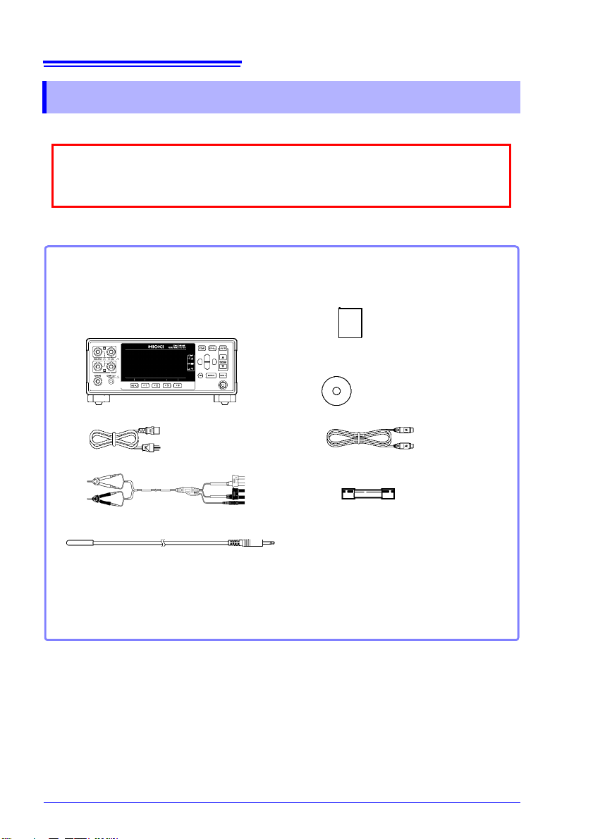
When you receive the instrument, inspect it carefully to ensure that no damage
occurred during shipping. In particular, check the accessories, panel switches, and
connectors. If damage is evident, or if it fails to operate according to the specifications, contact your authorized Hioki distributor or reseller.
Confirm that these contents are provided.
Model RM3545 or
RM3545-01 (with GP-IB included) or
RM3545-02 (with Multiplexer
Slot included)..1
Power Cord (2-line + ground) (p. 35).............1
Model L2101 Clip Type Lead .........................1
Model Z2001 Temperature Sensor ................1
EXT I/O Male Connector (p. 219)...................1
Instruction Manual (This document)... 1
Application disc (CD)*........................1
(Communications Command
Instruction Ma nual, USB dr iver )
USB cable (A-B type).........................1
Spare Fuse (F1.6AH/250V) ...............1
* The latest version of the application disc can be downloaded from the Hioki web site.
Verifying Package Contents
Verifying Package Contents
Inspection
Content confirmation
Page 11
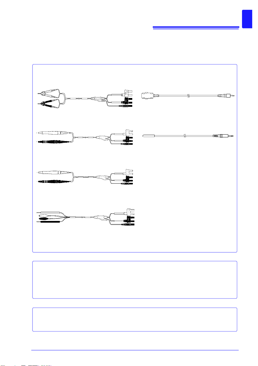
Options
Measurement
Model L2101 Clip Type Lead
Model L2102 Pin Type Lead
Model L2103 Pin Type Lead
Model L2104 4-Terminal Lead
Interface Cables
Model 9637 RS-232C Cable (9pin-9pin/ 1.8 m/ crossover cable)
Model 9638 RS-232C Cable (9pin-25pin/ 1.8 m/ crossover cable)
Model 9151-02 GP-IB Connector Cable (2 m)
Model L2105 LED Comparator Attachment
Model Z2001 Temperature Sensor
Multiplexer Unit
Model Z3003 Multi pl exer Unit
Contact your authorized Hioki distributor or reseller for details.
See: "Appendix 16 Measurement Leads (Options)" (p. A34)
3
Verifying Package Contents
Page 12
4
Safety Information
Safety Information
This instrument is designed to conform to IEC 61010 Safety Standards, and has been thoroughly tested for safety prior to shipment.
However, using the instrument in a way not described in this manual may negate the provided safety features.
Before using the instrument, be certain to carefully read the following safety notes.
Mishandling during use could result in injury or death, as well as damage to the product. Be certain that you understand the instructions and
precautions in the manual before use.
With regard to the electricity supply, there are risks of electric shock,
heat generation, fire, and arc discharge due to short circuits. If per sons
unfamiliar with electricity measuring instruments are to use the product, another person familiar with such instruments must supervise
operations.
This manual contains information and warnings essential for safe operation of the instrument and for maintaining it in safe operating condition. Before using it, be sure to carefully
read the following safety precautions.
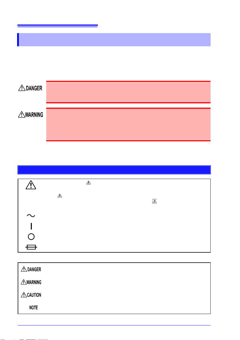
Safety Symbols
In the manual, the symbol indicates particularly important information that the
user should read before using the instrument.
The symbol printed on the instrument indicates that the user should refer to a
corresponding topic in the manual (marked with the symbol) before using the
relevant function.
Indicates AC (Alternating Current).
Indicates the ON side of the power switch.
Indicates the OFF side of the power switch.
Indicates a fuse.
The following symbols in this manual indicate the relative importance of cautions and warnings.
Indicates that incorrect operation presents an extreme hazard that could result in
serious injury or death to the user.
Indicates that incorrect operation presents a significant hazard that could result in
serious injury or death to the user.
Indicates that incorrect operation presents a possibility of injury to the user or damage to the instrument.
Indicates advisory items related to performance or correct operation of the instrument.
Page 13
Safety Information
Symbols for Various Standards
This symbol indicates that the product conforms to regulations set out by the EC
Directive.
WEEE marking:
This symbol indicates that the electrical and electronic appliance is put on the EU
market after August 13, 2005, and producers of the Member States are required to
display it on the appliance under Article 11.2 of Directive 2002/96/EC (WEEE).
Other Symbols
Indicates the prohibited action.
(p. )
[ ]
SET
(Bold characters)
Unless otherwise specified, “Windows” represents Windows XP, Windows Vista, Windows 7, or
Windows 8.
Indicates the location of reference information.
*
Indicates that descriptive information is provided below.
Square brackets indicate instrument display labels (such as setting item names).
Bold characters within the text indicate operating key labels.
Accuracy
We define measur ement tol erance s in te rms o f f. s. (fu ll scal e), rd g. (r eading ) and dgt. (di git) va lues , wit h the
following meanings.
f.s.
rdg.
dgt.
See: "Example accuracy calculations" (p. 259)
(maximum display value)
This is usually the name of the maximum displayable value. For this instrument , it
indicates the currently selected range.
(reading or displayed value)
The value currently being me as ur ed and ind ica ted on the measuring instrument .
(resolution)
The smallest displaya bl e un it on a di gi tal measuring instrument, i.e., the input val ue
that causes the digital display to show a “1” as the least-significant digit.
5
Page 14
6
Operating Precautions
Operating Precautions
Follow these precautions to ensure safe operation and to obtain the full benefits of the various functions.
Preliminary Checks
Before using the instrument for the first time, verify that it operates normally to ensure that
no damage occurred during storage or shipping. If you find any damage, contact your
authorized Hioki distributor or reseller.
Before using the instrument, make sure that the insulation on the
power cord, leads or cabl es i s undamaged and that no bare conductors
are improperly exposed. Using the instrument in such condi tions could
cause an electric shock, so contact your authorized Hioki distributor or
reseller for replacements.
Page 15
Instrument Installation
The instrument can be used with the stand (p. 24).
It can also be rack-mounted. (p. A35).
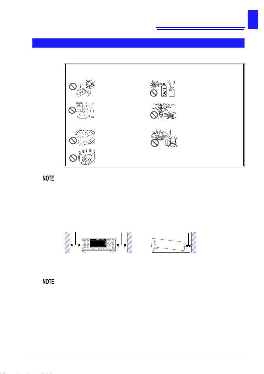
50 mm or more
10 mm or more
Rear
50 mm or more
Operating temperature and humidity: 0 to 40°C at 80% RH or less (non-condensating)
Storage temperature and humidity : -10°C to 50°C at 80% RH or less (non-condensating)
Avoid the following locations that could cause an accident or damage to the
instrument.
Correct measurement may be impossible in the presence of strong magnetic
fields, such as near transformers and high-current conductors, or in the pre sence of strong electromagnetic fields such as near radio transmitters.
Exposed to direct sunlight
Exposed to high temperature
Exposed to water, oil,
other chemicals , or solvents
Exposed to high humidity or condensation
Exposed to high levels
of particulate dust
Subject to vibration
7
Operating Precautions
In the presence of corrosive or
explosive gases
Exposed to strong electromagnetic fields
Near electromagnetic radiators
Near induction heating systems
(e.g., high-frequency induction heating systems and IH
cooking utensils)
Installation Precautions
• The instrumen t should be operated only with the bottom downwards.
• Do not place the instrument on an unstable or slanted surface.
Unplugging the power cord kills power to the instrument. Be sure to provide
enough unobstructed space to unplug the power cord immediately in an
emergency.
Page 16
8
Operating Precautions
Handling the Instrument
• Do not allow the instrument t o get w et , a nd do not take measurements
with wet hands. This may cause an electric shock.
• Do not attempt to modify, disassemble or repair the instrument; as
fire, electric shock and injury could result.
• To avoid damage to the instrument, protect it from physical shock when
transporting and handling. Be especially careful to avoid physical shock
from dropping.
• To avoid damage to the instrument, do not apply voltage or current to mea-
surement terminals, TEMP.SENSOR jack, TEMP.ANALOG INPUT terminal
block, COMP.OUT jack, or D/A OUTPUT terminal block.
• This instrument may cause interference if used in residential areas. Such
use must be avoided unless the user takes special measures to reduce
electromagnetic emissions to prevent interference to the reception of radio
and television broadcasts.
• Use the original packing materials when transporting the instrument, if pos-
sible.
Page 17
Handling the Cords and Leads
To avoid electrical shock, be careful t o avoid shorting live lines with the
test leads.
• Avoid stepping o n or pinching cables, which could damage t he cable insul a-
tion.
• To avoid breaking cables or lead wires, do not bend or pull them.
• To avoid damaging the power cord, grasp the plug, not the cord, when
unplugging it from the power outlet.
• To avoid damaging the cable, grasp the connector, not the cable, when
unplugging the cable.
• The ends of the pin type lead are sharp. Be careful to avoid injury.
• Keep the cables well away from heat sources, as bare conductors could be
exposed if the insulation melts.
• Temperature sensors are precision devices. Be aware that excessive volt-
age pulses or static discharges can destroy the film.
• Avoid subjecting the temperature sensor tip to physical shock, and avoid
sharp bends in the leads. These may damage the probe or break a wire.
• Use only the specified cords and leads. Using a non-specified cord or lead
may result in incorrect measurements due to poor connection or other reasons.
• If the part of the temperature sensor that connects to the instrument
becomes dirty, wipe it clean. The presence of dirt may affect temperature
measured values by increasing the contact resistance.
• Exercise care so that the temperature sensor connector does not become
disconnected. (If the sensor is disconnected, it will not be possible to perform temperature correction or temperature conversion.)
9
Operating Precautions
CD-R disc precautions
• Exercise care to keep the recorded side of discs free of dirt and scratches.
When writing text on a disc’s label, use a pen or marker with a soft tip.
• Keep discs inside a protective case and do not expose to direct sunlight,
high temperature, or high humidity.
• Hioki is not liable for any issues your computer system experiences in the
course of using this disc.
Page 18
10
Operating Precautions
Before Connecting the Power Cord
• To avoid electrical accidents and to maintain the safety specifications
of this instrument, connect the power cord provided only to a 3-contact (two-conductor + ground) ou tl et .
• Use only the design ate d power cord with this instrument. Use of other
power cords may cause fire.
• Before using the instrument, make sure that the insulation on the
power cord is undamaged and that no bare conduct ors are impr operly
exposed. Any damage could cause electric shock, so contact your
authorized Hioki distributor or reseller.
To avoid damaging the power cord, grasp the plug, not the cord, when
unplugging it from the power outlet.
Before Connecting Measuremen t Leads
To avoid shock and short circuits, turn off all power before connecting
measurement leads.
Before Connecting the LED Comparator Attachment
• To keep from damaging the instrument or LED Comparator Attachment,
turn off the instrument before connecting the attachment.
• The COMP.OUT jack is provided exclusively for use with the L2105. Do not
connect any device other than the L2105.
• The attachment may not fulfill the specifications if the connector is not
attached securely.
• Do not over-tighten the cable tie around the measurement leads. Doing so
may damage the measurement leads.
• Avoid the following as damage to the cable conductor or insulation may
result:
Twisting or pulling on cables
Bending cables near the lamp excessively in order to connect them
Page 19
Before Connecting the Temperature Sensor
Failure to fasten the connectors properly may result in sub-specification performance or damage to the equipment.
Note the following precautions to avoid damaging the instrument:
• To keep from damaging the instrument or temperature sensor, turn off the
instrument’s main power switch before connecting the sensor.
• Connect the temperature sensor by inserting the plug all the way into the
TEMP.SENSOR jack. A loose connection can cause a large error component in measured values.
• If the temperature sensor jack becomes di rty, wipe it clean. The pr esence of
dirt will cause an error in temperature measured values.
• When connecting the temperature sensor, do not connect anything to the
TEMP.ANALOG INPUT terminal block. Doing so may cause erroneous
measured values to be displayed.
Before Connecting the Thermometer
• Note that thermometer circuit is grounded. To avoid electric shock
accidents or damage to the instrument, do not connect an analog output thermometer to the TEMP.ANALOG INPUT terminal block that ha s
any potential offset from ground.
• Failure to fasten the connectors properly may result in sub-specifica-
tion performance or damage to the equipment.
11
Operating Precautions
Note the following precautions to avoid damaging the instrument:
• Before connecting a thermometer t o t he instrument, confirm that any power
to the instrument and thermometer is turned OFF.
• Allowable input voltage from an analog thermometer is 0 to 2 V (between
terminal contacts). Do not apply voltage exceeding this range.
• With thermometers providing 4 to 20 mA output, connect a shunt resistance
of about 50 before connecting, and convert the resulting voltage.
• When connecting the thermometer, do not connect anything to the
TEMP.SENSOR jack. Doing so may cause erroneous measured values to
be displayed.
Page 20
12
Operating Precautions
Before Connecting Data Cables (US B, RS-232C, GP-IB)
• Failure to fasten the connectors properly may result in sub-specifica-
tion performance or damage to the equipment.
• Always turn both devices OFF when connecting and di sconnecting an
interface (except USB) connector. Otherwise, an electric shock accident may occur.
Observe the following precautions when connecting the instrument and a
controller:
• To avoid faults, do not disconnect or reconnect the USB cable d uring instru-
ment operation.
• The USB, RS-232C, and GP-IB interfaces are not isolated from the ground
circuit. Connect the instrument and the controller to a common earth
ground. Using different grounds could result in potential difference between
the instrument and the controller. Potential difference on the data cable can
result in malfunctions and faults.
Before Connecting the Printer
Because electric shock and instrument damage hazards are present,
always follow the steps below when connecting the printer.
• Always turn off the instrument and the printer before connecting.
• A serious hazard can occur if a wire becomes dislocated and contacts
another conductor during operation. Make certain connections are
secure.
Before Switching between Current Sink (NPN) and Current Source (PNP)
• Configure the NPN/PNP setting to accommodate externally connected
equipment.
• Do not operate the NPN/PNP switch while the instrument is on.
Page 21
Before Connecting EXT I/O
To avoid electric shock or damage to the equipment, always observe
the following precautions when connecting to the EXT I/O connect or.
• Always turn off the main power switch on the instrument and on any
devices to be connected before making connec tions.
• Be careful to avoid exceeding the ratings of external terminals (p.
206).
• During operation, a wire becoming dislocated and contacting another
conductive object can be serious hazard. Use screws to secure the
external connectors.
• The ISO_5V pin of the EXT I/O connector is a 5V (NPN)/ -5V (PNP)
power output. Do n ot apply ext ernal power t o thi s pin. (Exte rnal p owe r
cannot be supplied to the instrument’s EXT I/O connector.)
To avoid damage to the instrument, observe the following cautions:
• Do not apply voltage or current to the EXT I/O terminals that exceeds their
ratings.
• When driving relays, be sure to install diodes to absorb counter-electromo-
tive force.
• Be careful not to short-circuit ISO_5V to ISO_COM.
• Configure the NPN/PNP setting to accommodate externally connected
equipment.
• Do not operate the NPN/PNP switch while the instrument is on.
See: "Connector Type and Signal Pinouts" (p. 179)
13
Operating Precautions
Page 22
14
Operating Precautions
Before Attaching a Multiplexer Unit
Before Connecting the Multiplexer’s Connector
• To avoid electric shock, before removing or replacing a Multiplexer
Unit, confirm that the instrument’s main power switch is off and that
the measurement leads, power cord, and all connectors have been
disconnected.
• The mounting screws must be firmly tightened or the Multiplexer Unit
may not perform to specifications, or may even fail.
• Failure to fasten the connectors properly may result in sub-specifica-
tion performance or damage to the equipment.
• When connecting a measurement target with electromotive force (a
battery or power supply), take steps to protect against short-circu its.
• The Z3003 Multiplexer Unit’s maximum allowable voltage for contacts
is 33 V RMS/46.7 V peak, or 70 V DC. Do not connect directly to a
dielectric strength tester or insulation resistance tester.
• To avoid the danger of electric shock, never operate the instrument
with a multiplexer unit removed. To use the instrument after removing
a multiplexer unit, install a blank panel over the opening of the
removed unit.
• When inserting in the unit, hold the metal plate. Directly touching the board
may cause damage of the unit or accuracy deteriorations in the higher
resistance ranges due to the influence of static electricity. Taking countermeasures against static electricity (using antistatic devices such as a wrist
strap) as well as wearing antistatic gloves are recommended.
• To prevent malfunctions when not using the Multiplexer Unit, store it using
the packaging materials in which it was delivered.
Before Using D/A Output
• To avoid electric shock and instrument damage when connecting a device
to the instrument’s D/A output terminal, turn off main power switch on the
instrument and the device being connected and ensure that the measurement leads have been disconnected from the measurement target.
• The maximum output voltage that can be generated from the D/A output is
5 V . If the rated vol tage of the device being conne cted is less than 5.5 V, the
connected device could be damaged.
• D/A output is not isolated from the gro und circuit. If the device connected to
D/A output is not isolated from the ground circuit, the error component in
measured values will increase.
Page 23
Before Turning Power On
Before turning the instrument on, make sure the supply voltage
matches that indicated on its power connector. Connection to an
improper supply voltage may damage the instrument and present an
electrical hazard.
Avoid using an uninterruptible power supply (UPS) or DC/AC inverter with
rectangular wave or pseudo-sin e-wave output t o power t he instru ment. Doing
so may damage the instrument.
15
Operating Precautions
Page 24
16
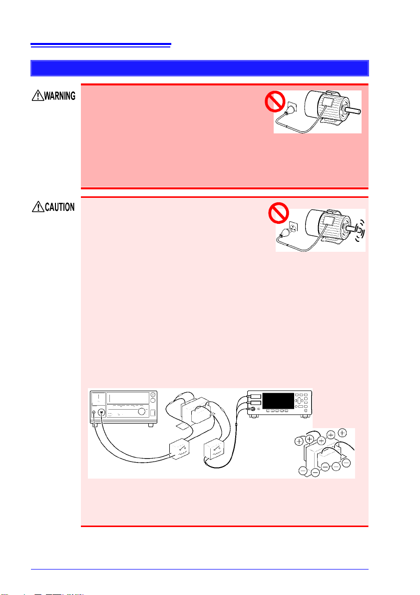
The measurement target is
connected to a power supply.
• Never attempt to measure at a point where volt-
age is present. Even if the power supply to the
motor is turned off, while the motor is rotating
inertially, high electromotive power is generated
in terminals. When attempting to measure a
transformer or motor immediately after voltage
withstanding test, induced voltage or residual
charge may damage the instrument.
Rotating inertially
• When the RM3545 is used in a way that connects to a withstanding voltage
tester via switching relays, construct a testing line bearing the following in
mind.
See: "Appendix 15 Using the Instrument with a Withstanding Voltage Tester" (p. A33)
(1) The voltage withstanding specification of switching relays should
include a safe margin over the withstanding testing voltage.
(2) To protect against damage due to arc discharge in relay contacts, all
RM3545 measurement terminals should be grounded during voltage
withstanding testing.
(3) To protect against damage due to residual charge, measure resistance
first, and voltage withstanding last.
3158 AC Withstanding Voltage HiTester RM3545
Withstand voltage of relay switch is not high enough.
Residual charge from voltage
withstanding test is present.
Operating Precautions
Before Measuring
• To avoid electric shock or damage to the
instrument, do not apply voltage to the
measurement terminals. Also, to avoid
electrical accidents, only take measurements after turning off the power to the
measurement targets being measured.
• Sparks may result at the moment the instrument is connected to, or
disconnected from, the measurement target. To avoid fire or bodily
injury, avoid use in the presence of explosive gases.
• Battery internal resistance cannot be measured with this instrument. It will
sustain damage. To measure battery internal resistance, we recommend the
HIOKI 3554, 3555, BT3562, BT3563 and 3561 Battery HiTesters.
Page 25
• To obtain the guaranteed measurement accuracy, allow at least 60 minutes
warm-up.
• When measuring devices such as power supply transformers with high
inductance or open-type solenoid coils, measured value may be unstable.
In such cases, connect a film capacitor of about 1 F between SOURCE A
and SOURCE B.
• Carefully insulate all SOURCE A, SENSE A, SENSE B, and SOURCE B
wiring. Proper 4-terminal measurements cannot be performed and an error
will occur if core and shield wires touch.
• The SOURCE terminal is protected by a fuse. If the fuse is tripped, the
instrument will display “
Blown Fuse.” and you will not be able to measure
resistance values. If the fuse is tripped, replace the fuse.
See: "14.2 Replacing the Measurement Circuit’s Protective Fuse" (p. 302)
• Since the instrument uses DC current for measurement, it may be affected
by thermal EMF, resulting in a measurement error . If so, use the Offset V o ltage Compensation function (OVC).
See: "4.8 Compensating for Thermal EMF Offset (Offset Voltage Compensation -
OVC)" (p. 82)
See: "Appendix 9 Effect of Thermal EMF" (p. A23)
When using the temperature sensor
The temperature sensor is not waterproof. Do not submerse it in water or
other liquid.
17
Operating Precautions
• Allow the measurement target for which temperature correction is being
performed and the temperature sensor to adjust to the am bient temper ature
prior to measurement. Failure to do so will result in a large error component.
• Handling of the temperature sensor with bare hands may cause the sensor
to pick up inductive noise, resulting in unstable measured values.
• The temperature sensor is designed for use in applications in which ambi-
ent temperature is measured. It is not possible to accurately measure the
temperature of the measurement target itself by placing the sensor in contact with the surface of the target. Use of an infrared thermometer to perform correction is appropriate when there is a large temperature difference
between the ambient environment and the measurement target.
• Connect the temperature sensor by inserting the plug all the way into the
TEMP.SENSOR jack. A loose connection may cause a large error component in measured values.
Page 26

18
Operating Precautions
Page 27

19
• Measurement range: 10 m to 1000 M/ Basic accuracy: 0.006%rdg.
• Maximum resolution: 10 n
Supports low-resistance measurement of current detection resistors, reactors, welds, etc.
• Up t o 1 G range
Can be used in open testing of contacts.
• Discharge vol tage of 20 mV or less
Low-power measurement can be used in testing under IEC 60512-2 and other contact
standards.
• Accuracy defined without zero-adjustmen t
Conduct measurement with peace of mind, even without performing zero-adjustment.
• Wiring resistance tolerance in low-resistance range: 1.5
Measurement cables can be extended easily, even when using the 1 A measurement current range.
High-performance specifications to meet advanced development
and production needs
1.1 Product Overview and Features
Overview Chapter 1
1.1 Product Overview and Features
The RM3545 is capable of performing high-speed, high-precision measurement of the
winding resistance of components such as motors and transformers, the contact resistance
of relays and switches, the pattern resistance of printed circuit boards, and the DC resistance of fuses, resistors, and materials such as conductive rubber using four-terminal measurement. Since the instrument incorporates a temperature correction function, it is
particularly well suited to the measurement of targets whose resistance values vary with
temperature. It also provides features such as a comparator function, communications,
external control, and a multiplexer*, allowing it to be used in a wide range of applications,
including in development work and on production lines.
* The multiplexer can be used with the RM3545-02.
1
Page 28
20
LED Comparator Attachment (option)
Streamlines work by eliminating the need to look at the screen.
Graphical LCD
Operation is intuit ive and easy to l earn.
Easy configuration of comparator and panel
load operation
Facilitates smooth se tup changes o n production lines.
Simple basic settings
Range and measurement
speed can be set directly.
Guard terminal
You can reduce the
effects of external
noise by connecting the guard terminal.
Free power supply (100 to 240 V) with
automatic frequency switching
Allows the instrument to be easily moved to
overseas production lines.
Judgment sounds with user-selectable patterns
Keeps you from mistaking audio from a
nearby operator ’s instrument as your own.
Easy-to-use functions in research and development,
on production lines, or in acceptance inspections
Monitor and test functions
Provides robust support for line development by allowing you to check
communications and E XT I/ O on th e
screen.
Example communic ations
monitor screen
Example EXT I/O test
screen
Support for a variety of temperature sensors
You can connect a radiation thermometer with
analog output in addition to the included sensor.
Extensive selection of interfaces
Standard USB, RS-2 32C, EXT I/O , and D/
A output interfaces
(The RM3545-01 also provides a GPIB interface.)
1.1 Product Overview and Features
Page 29
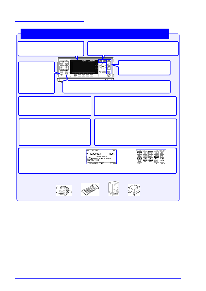
1.1 Product Overview and Features
• Measure up to 20 locations with 4-terminal measurement or 42 locations with
2-terminal measurement (when using two Z3003 units).
• Multipoint measurement
Allows measurement of network resistors, steering switches, 3-phase motors, etc.
• Total judgments
Outputs total judgment based on measurement results for tested locations.
• Comparator judgments based on measurement results
Allows judgments to be based on comparisons with standard elements for measurement
targets such as thermistors that are susceptible to the effects of temperature.
• External instrument connectivity
Allows multipoint measurement, including for external measuring instruments such as LCR
meters.
Multiplexer support to allow multipoint measurement and total
judgments (RM3545-02)
Z3003 Multiplexer Unit
21
1
Page 30
22
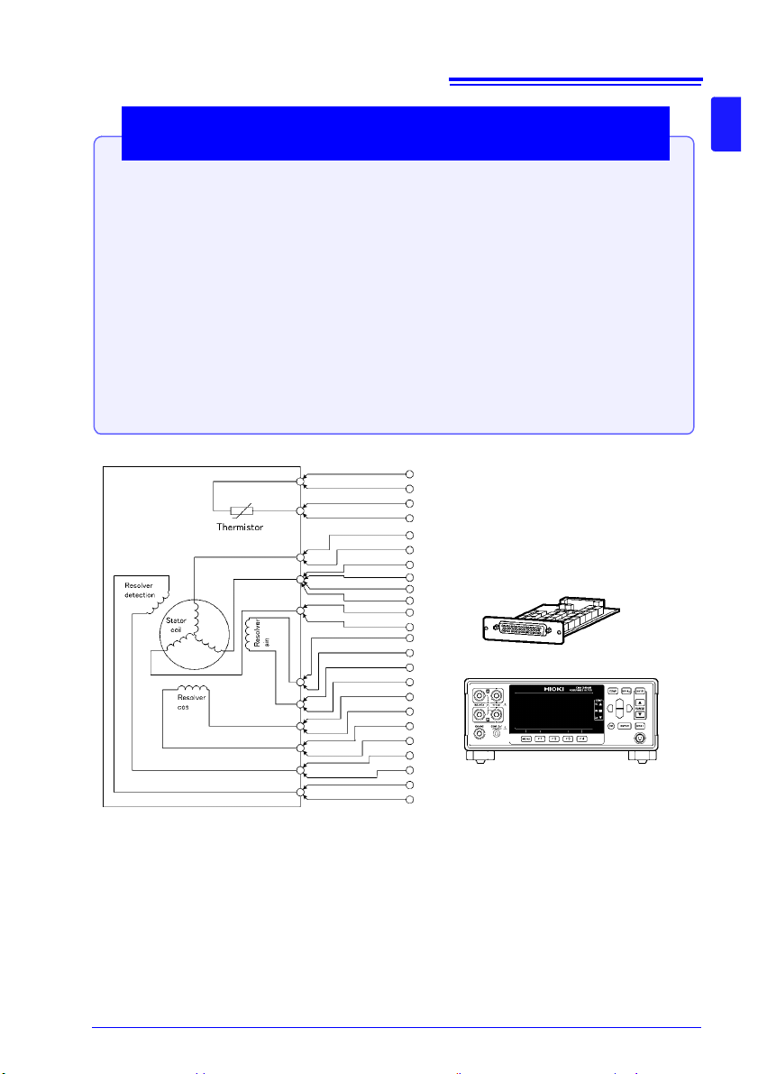
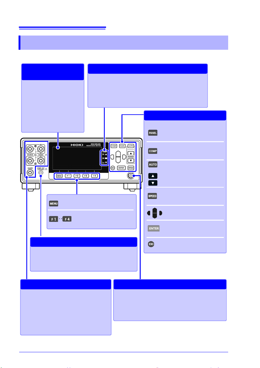
Display Screen (Monochrome graphical LCD)
Display of measuremen ts and
settings (p. 27)
Viewing Measured
Values and Settings
COMP indicator LEDs
Indicate the judgment result of the measured value (p.98).
Hi Measured value is above upper limit
IN Pass (meets criteria)
Lo Measured value is below lower limit
Viewing Comparator Results
MENU key
Switching of F key pages
F keys
Selection of settings displayed
on the screen
COMP.OUT jack
Connect the L2105 LED Comparator Attachment to
view judgment re sults without needing to refe r to the
instrument display. (p.107)
Connecting the LED Compa rator Att achment
PANEL key
Saving and loading of panels
(p.120)
COMP key
Configuration of comparator
settings (p.98)
AUTO, RANGE key
Range switching (p.49)
SPEED key
Measurement speed switch ing
(p.50)
Cursor keys
Selection of settings and digits
ENTER key
Acceptance of settings and
manual trigger input
ESC key
Cancellation of operation
Settings
Measurement T erminals
Connect measurement leads (p. 36).
• SOURCE A : Current detection terminal
• SOURCE B : Current source terminal
• SENSE A : Voltage detection terminal
• SENSE B : Voltage detection terminal
• GUARD : Guard terminal
Connecting Measurement Leads
STANDBY Key: Initiates or cancels the
standby stat e. (p . 43) .
• Unlit: power off (when no power supplied)
• Red light: Standby State (while power is supplied)
• Green light: power on
Initiating and Canceli ng the Standby St a te
1.2 Names and Functions of Parts
1.2 Names and Functions of Parts
Front Panel
Page 31

Rear Panel
RS-232C connector
• Connect to a computer, PLC, or other
device (p.226).
• Connect to a printer (p.239).
RS-232C Communications
Printer Output
Power Inlet
Connect the supplied power cord
(p. 35).
Connecting
the Power
Cord
Manufacturer's Serial Number
Do not remove this label, as it is required
for product support.
Fuse holder (p.302)
Replacing the
Measurement Fuse
Main power switch (p.43)
: Main power off
: Main power on
Turning the Main Power
On and Off
EXT I/O connector
Connect when controlling the instrument with
a PLC, I/O board, or other equipment to allow
measurement to be started and measured
values and comparator results to be acquired
(p.177).
External Control
USB jack
Connect to a computer
(p. 223).
Sending and
Receiving Data
via USB
EXT I/O NPN/PNP switch
Left : Current sink (NPN)
Right: Current source (PNP)
Switching between
NPN and PNP
TEMP.SENSOR jack/
TEMP.ANALOG INPUT terminal block
Connect the Z2001 Temperature Sensor or thermometer with analog outpu t when using t emper ature
correction or temperature conversion. (p.37)
Connect the Z20 01 to the TEMP.S ENSOR jack on
the right. Connect analog voltage output from a radiation thermometer or a shunt resistor for analog current output from a radiation thermometer to the
TEMP.ANALOG INPUT terminal block.
Correcting Temperature
Converting Temperature
D/A OUTPUT terminal block
The D/A OUTPUT terminal block outp uts r esistance values as a voltag e signal . (Conne ct a device that can acce pt vo ltag e inpu t, for exam ple
a Memory HiCorder.) (p.175)
D/A Output
RM3545-01
GP-IB Connector
(RM3545-01 only)
Connect to a compute r, or other device
(p.230)
GP-IB Communications
23
1.2 Names and Functions of Parts
1
Page 32

24
Multiplexer Unit Slot
(RM3545-02 only)
Installing the Z3003 Multiplexer Unit
(up to 2 units) (p.42)
Using the Multiplexer Unit
RM3545-02
Bottom Panel
Stand
When using the stand
Extend the legs all the way. Do not extend partially.
Make sure to extend both legs of the stand.
Collapsing the stan d
Do not collapse the stand partw a y. Be sure to col lap se
it all the way.
This instrument can be rack mounted.
See: "Appendix 17 Rack Mounting" (p. A35)
Parts removed f r om this instrument should be
stored in a safe place to enable future reuse.
Do not apply heavy downward pressure
with the stand extended. The stand coul d
be damaged.
1.2 Names and Functions of Parts
Page 33

25
2
6
5
3
Install the Multiplexer Unit
(RM3545-02; as necessary)
4
Install this instrum e nt (p. 6)
1
Rear Panel
Front Panel
Tu rn on the instrument and cancel
the standby state
(p.43)
6
When finished measuring, turn the
power off (p.43).
Connect the temperature sensor
or infrared thermometer (p.37)
(When using the temperature correction function or T)
4
2
3
Make instrument settings
*1
7
Connect measurement leads (p.36)
Check the measurement target
(p.48)
8
Connect to the test sample (p.51)
9
Connect the power
cord (p.35)
Connect the external interface
(as needed)
5
• Using the printer (p.239)
• Using the USB, RS-232C or GP-IB
interface (p. 221)
• Using the EXT I/O (p. 177)
• Using D/A Output (p. 175)
Rear Front
(Connect connectors
to the Multiplexer
Unit as necessary.)
When clipping a small-gauge
wire
(Clip with the tip of the alligator
clips.)
When clipping a large-gauge
wire
(Clip with the back of the alligator
clips, where there are no teeth.)
1.3 Measurement Process
1.3 Measurement Process
1
Page 34

26
1.3 Measurement Proces s
*1 About zero-adjustment
Perform zero-adjustment in the following circumstances:
• The measured value is not cleared due to thermal EMF or other factors.
The measured value will be adjusted to zero. (*2)
• Four-terminal connection (called Kelvin connection) is difficult.
The residual resistance of the two-terminal connection wires will be canceled.
See: "4.3 Zero Adjustment" (p.68)
"Appendix 6 Zero Adjustment" (p.7)
*2 Accuracy specifications vary when zero-adjustment has not been performed.
For more information, see "Chapter 13 Specifications" (p.251).
Thermal EMF can also be canceled by using OVC.
See: "4.8 Compensating for Thermal EMF Offset (Offset Voltage Compensation - OVC)" (p.82 )
Page 35

27
Trigger source (INT/EXT)
Measurement range
TC (ON)
0ADJ (ON)
Auto range
Key lock state or remote state
Cancel the key lock state or remote
state by pressing and ho lding the
MENU key.
F.LOCK : All operations prohibited .
M.LOCK: Menu operations prohibited.
RMT : Remote state
Judgment value
Switched with the VIEW key
(No display / temperature /
pre-calculation resistance
value)
Page switching
Measurement scre en la yo u t
Hold state
Scaling (ON)
Measurement speed
Number and name
of loaded panel
Measured value
OVC (ON)
1.4 Screen Organization and Operation Overview
1.4 Screen Organization and
Operation Overview
The instrument’s screen interface consists of a Measurement screen and various Settings
screens.
The screen examples in this guide appear reversed (black on white) for best visibility on the
printed page. However, the instrument screens can actually be displayed only as white
characters on black background.
1
Display of information other than measured values
(For more information, see "Confirming Measurement Faults" (p.55).)
Display Description
+OvrRng
-OvrRng
CONTACT TERM.A
CONTACT TERM.B
- - - - - - -
* To treat current faults (when the source wiring is open) as over-range events, change the
current fault output mode setting. (p.59)
Over-range
Contact error
Not measured, or broken connection in measurement target *
Page 36

28
Channel number
Total judgment result
Individual channels’ measured value
Individual channels ’ com par ato r re sul t
(If a measured va lue fa ult occu rs, a des cript ion of the er ror i s dis play ed.)
Individual channels’
PASS/FAIL judgment result (If a measured value
fault occurs, ”---” is dis-
played.)
Overview of screen operation
Menu switching
(4) To Settings screens
(1) Measurement screen
(2) Comparator Settings screen
Upper limit
value
Lower limit
value
(3) Panel Save/Load screen
Select a panel number.
3
Change
values.
Move among
digits.
Accept the setting with the
key or cancel with the key.
4
Change the range with the
and keys.
2
1
2
Perform action with an F key.
1
Select the mode with an F key.
When the measurement te rminal setting
is MUX (multiplexer): Select a channel.
P.3/3 is only displayed on
the RM3545-02.
1.4 Screen Organization and Operation Overview
When the scan function is set to auto or step (RM3545-02 only)
Page 37

(4) Settings screen
< Setting values >
Make the value editable with the
key.
2
Change values.
1
Move among
digits.
Accept the setting with the key
or cancel with the key.
3
Return to the Measurement screen
with the key.
Move to the [MEAS], [SYS], [I/O],
[IF], [BIN], [MUX1], or [MUX2] tab.*
* MUX1/MUX2 is only di splayed on the
RM3545-02.
1
2
Select a
setting.
Move among
settings.
Switch functions with an F key or set
values.
3
4
When the measurement terminal setting is MUX (multiplexer)
[CH−]: Changes (decreases) the
channel.
Set the measurement conditions by
channel.
[CH+]: Changes (increases) the
channel.
29
1.4 Screen Organization and Operation Overview
1
Page 38

30
1.4 Screen Organization and Operation Overview
List of settings
Screen Setting and key Overview See
Measurement screen COMP Comparator function (p.100)
PAN EL Save/load panel (p.119)
Measurement screen
(P.1/2) (For the RM3545-02, P.1/3)
Measurement screen
(P.2/2) (For the RM3545-02, P.2/3)
Measurement screen
*2
(P.3/3)
Settings
screen
(SETTING)
Multiplexer Channel
Settings screen
*2
(MUX1)
Multiplexer Basic
Measurement screen
*2
(MUX2)
AUTO
(RANGE)
SPEED Measurement speed (p.50)
INFO (F1) Display setting conditions
VIEW (F2)
STAT (F3)
STOP (F3)
PRINT (F4) Print (p.241)
0 ADJ (F2) Zero-adjustment
LOCK (F3) Key lock (p.126)
SETTING (F4) Switch to Settings screen
FRONT (F1) Use of the multiplexer
SCANSET (F3) Scan function
CH Use of channels
TERM Channel terminals
INST
0ALL
0ADJ
SPD
RANGE Individual channels’ range
UPP/REF
LOW%
PASS
*2
Measurement range (p.49)
(p.54)
Switch measur ement scre en
display
Display statistical calculation results
Stop scan
Use the front measurement
terminals
Measuring instruments for
each channel
Scan channels
Zero-adjustment settings
Individual channels’ zeroadjustment s tatus
Individual channels’ measurement speed
Individual channels’ comparator settings
Individual channels’ PASS
conditions
(p.52)
(p.111)
(p.68)
(p.151)MUX (F2)
(p.153)
(p.163)
(p.157)
Page 39

Settings
screen
(SETTING)
1.4 Screen Organization and Operation Overview
Screen Setting and key Overview See
Measurement
Setting screen
*3
(MEAS)
0 ADJUST Clear zero-adjustment (p.71)
TC SET Temperature correction (p.75)
T
Temperature conversion (p.116) R0, T0
k
DELAY Delay (p.84)
AVERAGE Averaging (p.73)
AUTO HOLD Hold measured value (p.60)
SCALING(A∗R+B)
A:
B:
UNIT :
OVC
LOW POWER
MEAS CURRENT
DIGITS Set the display digits (p.81)
CURR ERROR
MODE
CONTACT CHECK Contact check function (p.88)
CONTACT IMPRV Contact improver function (p.90)
100M PRECISION 100 M high-prec is io n m ode (p.96)
Scaling (p.77)
Offset voltage compensa-
tion function (OVC)
Low-power resistance mea-
surement (LP)
Switching me asur ement c ur-
rents
Current fault output format (p.59)
(p.82)
(p.64)
(p.66)
31
1
Page 40

32
1.4 Screen Organization and Operation Overview
Screen Setting and key Overview See
Settings
screen
(SETTING)
System Setting
screen
(SYS)
TERMINAL
*2
WIRE
*2
SCAN MODE
FAIL STOP
UNIT TEST
*2
*2
STATISTICS Statistical calculations function (p.11 1)
TEMP INPUT
ANALOG SET2
CALIBRATION Self-calibration (p.92)
KEY CLICK Set the operation sound (p.128)
COMP BEEP Hi
IN
Lo
PASS
FAIL
PANEL LOAD 0ADJ Load zero-adjustment values (p.122)
CONTRAST Set the contrast (p.131)
BACK LIGHT Set the contrast brightness (p.132)
POWER FREQ Set the power frequency (p.129)
CLOCK Clock settings (p.133)
RESET Reset the instrument (p.134)
ADJUST Adjust the instrument (p.A43)
EXT I/O Setting
screen
(I/O)
TRIG SOURCE Set the trigger source (p.208)
TRIG EDGE Set the trigger signal logic (p.210)
TRIG/PRINT FILT Trigger/print filter function (p.212)
EOM MODE EOM signal setting (p.214)
JUDGE/BCD MODE EXT I/O output mode (p.216)
EXT I/O TEST EXT I/O test (p.217)
Communication
Interface
Setting screen
(IF)
INTERFACE Configure interface settings (p.223)
SPEED
*1
GP-IB
DATA OUT
CMD MONITOR
PRINT INTRVL
STAT CLEAR
BIN Setting screen
(BIN)
*1 RM3545-01 only
*2 RM3545-02 only
*3 When using the multiplexer, the selecte d chan nel number will be displayed next to “MEAS.”
BIN BIN measurement settings (p.108)
Measurement terminal settings
Multiplexer measurement
*2
method
Scan function
Stop at FAIL during scan
Z3003 unit test (p.166)
Temperature sensor settings (p.37) ANALOG SET1
Set the judgment sound
(PASS/FAIL: RM3545-02
only)
Communications (p.221)
Printing (p.239)PRINT COLUMN
(p.148)
(p.105)
Page 41

33
1.5 Checking the Measurement Target
1.5 Checking the Measurement Target
To carry out proper resistance measurement, change the measurement conditions appropriately according to the measurement target. Before starting measurement, use the examples recommended in the following table to configure the instrument.
Recommended settings
Measure-
ment Current
(p.66)
TC/ T
(p. 75)
(p.116)
TC
TC ON
Low *1 − ON
−
OVC
(p.82)
OFF ON
OFF
Contact
check
(p.88)
OFF *3
OFF
ON
ON
Measurement target
Motors, solenoids, choke coils,
transformers
Signal contact
Wire harnesses, connectors,
relay contacts, switches
Power contact
Wire harnesses, connectors,
relay contacts, switches
Fuses, resistors
Conductive paint, Conduct ive rubber
(Bold indicates a change from the factory default.)
Low-Power
(p.64)
OFF High
ON − TC −
OFF High
OFF
OFF High
1
Other, Standard resistance measurement
Heaters, Electrical wires, Welds
Temperature-rise test
Motors, choke coils, transformers
OFF High *2
OFF High
T
ON
OFF ON
ON
*1: When there is sufficient margin with regard to the rated power, select High.
*2: When the measurement target significantly depends on temperature, use the tempera-
ture correction function.
*3: When there is sufficient margin with regard to the allowable applied voltage, select ON.
When measuring a commercial power supply transformer using an external trigger, mea-
surement cannot be performed using the delay setting preset. Either make the delay adequately long or measure using the internal trigger (p.84).
Page 42

34
1.5 Checking the Measurement Target
Page 43

Measurement
Rear Panel
1 Confirm that the instrument's Main power
switch (rear panel) is OFF( ).
2 Confirm that the mains supply voltage matches
the instrument, and connect the power cord to
the power inlet on the instrument.
3 Plug the power cord into the mains outlet.
If power to the instrument is cut off with the power switch
in the ON position (by a circuit breaker, etc.), the instrument will start up when power is restored, without any
need to press the STANDBY key.
Power inlet
Main power switch
35
2.1 Connecting the Power Cord
Preparations
Be sure to read the "Operating Precautions" (p.6) before installing and connecting this
instrument.
Refer to "Appendix 17 Rack Mounting" (p. A35) for rack mounting.
Chapter 2
2.1 Connecting the Power Cord
Turn off the power before disconnecting the power cord.
2
Page 44

36
Connection Methods
Connecting measurement leads
Connect the red plugs to the SOURCE A and
SENSE A terminals, the black plugs to the
SOURCE B and SENSE B terminals, and the
guard plug to the GUARD terminal.
When clipping a small-gauge wire
(Clip with the tip of the alligator clips.)
When clipping a large-g aug e wi re
(Clip with the back of the alligator clip s, where
there are no teeth.)
Measurement leads
(Example: When using the L2101 Clip Type Lead)
SENSE
SOURCE
The “V” mark indicates
the SENSE side.
SENSE
SOURCE
Red
Black
SENSE
SOURCE
SENSE
SOURCE
Red
Black
Red plugs
Black plugs
Guard plug
2.2 Connecting Measurement Leads
2.2 Connecting Measurement Leads
Connect the included or optional Hioki measurement leads to the measurement terminals.
Before connecting the measurement leads, read "Operating Precautions" (p.6) carefully.
Refer to "Options" (p.3) for details.
We recommend using optional Hioki measurement leads.
When making your own measurement leads or extending a measurement
lead, see "Appendix 13 Making Your Own Measurement Leads, Making
Connections to the Multiplexer" (p. A29).
Page 45

37
1 Confirm that the instrument's Main
power switch (rear panel) is OFF( ).
2 C onnect the Z2001 Temperature Sensor
into the TEMP.SENSOR jack on the rear
panel.
3 Place the tip of the temperature sensor
near the measurement target.
4 Configure temperature measurement.
Connection Methods
Connecting the Z2001 Temperature Sensor
Rear Panel
Z2001 Temperature Sensor
TEMP.SENSOR jack
Insert the Z2001 securely all the way into
the jack.
Do not connect anything to the
TEMP.ANALOG INPUT terminal block.
2.3 Connecting Z2001 Temperature Sensor or Thermometer with Analog Output (When using
2.3 Connecting Z2001 Temperature Sensor or
Thermometer with Analog Output
(When using the TC or T)
Connecting the Z2001 Temperature Sensor
Before connecting the temperature sensor, read "Operating Precautions" (p.6) carefully.
2
Page 46

38
The Settings screen
appears.
Switch the function menu
to P.2/3.
1
2
Move the cursor to the [SYS]
tab with the left and right cursor keys.
2
Thermistor sensor (Z2001)
Selection
1
Return to the
Measurement screen.
2.3 Connecting Z2001 Temperature Sensor or Thermometer with Analog Output (When using
After turning on the instrument, check whether the temperature measurement settings are
correct. Change if necessary.
Open the Settings Screen.
1
Open the System Setting Screen.
2
Select TEMP INPUT and press (SENSOR).
3
Return to the Measurement screen.
4
Page 47

2.3 Connecting Z2001 Temperature Sensor or Thermometer with Analog Output (When using
1 Confirm that the instrument's Main
power switch (rear panel) is OFF( ).
2 Connect the thermometer's analog output
connector to the TEMP.ANALOG INPUT terminal block on the rear panel, using a
cable.
3 Configure temperature measurement.
Connection Methods
Connecting an Analog Output Ther m o m et e r
Rear Panel
TEMP.ANALOG INPUT terminal block
Recommended
wire type
: Single line: AWG22 (0.65 mm diameter)
Twisted wire: AWG22 (0.32 mm
2
)
Diameter of search wire: 0.12 mm or more
Compatible wire
types
: Single line: AWG28 (0.32 mm diameter) to AWG22 (0.65 mm diameter)
Twisted wire: AWG28 ( 0.08 mm
2
) to AWG22 (0.32 mm2) stranded condu ctor
Diameter of search wire: 0.12 mm or more
Standard bare
wire length
:8 mm
Insert the thermometer's analog output
connector securely all the way into the
terminal block.
Do not connect anything to the
TEMP.SENSOR jack.
Connecting an Analog Output Thermometer
To measure temperature, connect the analog output thermometer to the instrument.
Before connecting the thermometer, read "Operating Precautions" (p.6) carefully.
39
2
When using a thermometer that generates 4 to 20 mA output, connect a shunt resistor of
about 50 between the positive and negative term ina ls an d conver t th e output to a voltage
prior to input. With a 50 resistor connected, the reference voltage (V
0.20 V (V
) and 1.00 V (V2).
1
, V2) settings are
1
Page 48

40
The Settings screen
appears.
Switch the function menu
to P.2/3.
1
2
Move the cursor to the [SYS]
tab with the left and right cursor keys.
2
Analog input
Selection
1
2.3 Connecting Z2001 Temperature Sensor or Thermometer with Analog Output (When using
After turning on the instrument, check whether the temperature measurement settings are
correct. Change if necessary.
Open the Settings Screen.
1
Open the System Setting Screen.
2
Select TEMP INPUT and press (ANLG-V).
3
Page 49

41
Move the cursor to the setting you
wish to configure. Make the value
editable with the key.
2
Move the cursor to the digit you
wish to set with the left and right
cursor keys. Change the value
with the up and down cursor keys.
Change
values.
1
Move among
digits.
3
Accept
( Cancel)
Setting range
reference voltage (V
1
, V2): 00.00 to 02.00 V (default V1: 0 V, V2: 1 V)
reference temperature (T
1
, T2): -99.9 to 999.9°C (default T1: 0°C, T2: 100°C)
Return to the
Measurement screen.
V1 V20
T1
T2
アナログ入力電圧
温度
T
2
−
T
1
V
2
−
V
1
⋅ (Inp ut V oltage) +
T1V
2
−
T2V
1
V
2
−
V
1
T
2
T
1
V
1
V
2
Temperature
Analog Input Voltage
2.3 Connecting Z2001 Temperature Sensor or Thermometer with Analog Output (When using
Set two reference voltages and the corresponding reference temperatures.
4
Set reference voltages V
Steps
1 through 3 for each.
Return to the Measurement screen.
5
and V2 and reference temperatures T1 and T2 by following
1
2
The displayed value is calculated by the following expression.
Page 50

42
Required item: One Phillips-head screwdriver
Installing a Multiplexer Unit
Rear panel
Blank panel
UNIT 1 UNIT 2
1 Turn off the instrument’s main power
switch and disconnect the cords and
leads.
2 Remove the two screws with a Phillips
head screwdriver and remove the blank
panel.
3 With attention to the orientation of the Mul-
tiplexer Unit, insert it firmly all the way in.
Insert the unit after aligning it with the
guide rail.
Taking countermeasures against static electricity
(using antistatic devices such as a wrist strap) as well
as wearing antistatic gloves are recommended.
4 Using the Phillips screwdriver, tighten the
two Multiplexer Unit mounting screws.
Configure the settings so that they match
the unit number used.
See: "Customizing Channel Pin Allocation" (p.152)
When using only one Multiplexer Unit, it can be installed as either UNIT 1 or UNIT 2.
Guide rail
Model Z3003
Do not directly touch the board
2.4 Installing the Multiplexer Unit
2.4 Installing the Multiplexer Unit
To use multiplexing capability, you must first install the Z3003 Multiplexer Unit.
Before connecting the Multiplexer Unit, read "Operating Precautions" (p.6) carefully.
Removing a Multiple xer U nit
After turning off t he instrument ’s main power switch and disconne cting all co rds and
leads, remove the Multiplexer Unit by reversing the above procedure and then att ach
the blank panel.
Page 51

2.5 Turning the Power On and Off
Turn on ( ) the main power switch on the rear of the
instrument.
If the main power switch was turned off while the
instrument was not in the standby state, the standby
state will be automatically canceled when the main
power switch is turned on.
Power ON
Turn off ( ) the main power switch on the rear of the
instrument.
Power OFF
Press the STANDBY key (the STANDBY
key will change from red to green).
2.5 Turning the Power On and Off
Turning On the Instrument with the Main Power Switch
Turning Off the Instrument with the Main Power Switch
43
2
Canceling the Standby State
Page 52

44
Self-test
Indicates an error (p. 298).
After the standby state is canceled, a self-test (instrument diagnostic routine) is performed.
During the self-test, the following information is displayed while the hardware is verified.
Error
No Errors
Normal display (measurement screen)
The following informatio n is dis playe d du r ing self -t est in g:
• Manufacturer and model name
• Firmware versions
• Communication interface setting
• Detected line frequency
• EXT I/O (NPN/PNP) setting
• Self-Calibration setting
• Inserted unit information (RM3545-02 only)
2.5 Turning the Power On and Off
The Z3003 Multiplexer Unit test is not performed during the self-test on startup.
See: "8.6 Performing the Multiplexer Unit Test" (p.166)
Before Starting Measurement
To obtain precise measurements, provide about 60 minutes warm-up after turning power
on.
The SOURCE terminal is protected by a fuse. If the fuse is tripped, the instrument will display “
Blown FUSE.” and you will not be able to measure resistance values. In this case,
replace the fuse.
See: "14.2 Replacing the Measurement Circuit’s Protective Fuse" (p.302)
Measurement settings are recalled from when the power was previously turned off (settings
backup).
Placing the Instrument in the Standby State
Press the Standby key (the Standby key will change from green to red).
Disconnect the power cord from the outlet to extinguish the standby key light.
When power is turned on again, operation resumes with the sa me state as w hen last turned
off.
If a power outage (e.g., breaker trip) occurs when the instrument is on, it will automatically
turn on again when power is restored (without pressing the standby key).
Page 53

2.6 Pre-Operation Inspection
Do not use the instrument if
damage is found, as electric
shock or short-circuit accidents
could resul t. Cont act yo ur auth orized Hioki distributor or reseller.
Metal Exposed
Is the power cord insulation torn, or
is any metal exposed?
1
Before using the instrument for the first time, verify that it operates normally to
ensure that no damage occurred during storage or shipping. If you find any damage, contact your authorized Hioki distributor or reseller.
Peripheral Device Inspection
Is the insulation on a measurement
lead torn, or is any metal exposed?
No Metal Exposed
If there is any damage, measured
values may be unstable and
measurement errors may occur.
Replace the cable with an undamaged one.
Metal Exposed
No Metal Exposed
If damage is evident, req uest repairs.
Yes
Is damage to the instrument evident?
Instrument Inspection
When turning power on
Is the STANDBY key red or green?
No
2
The power cord may be damaged, or the inst rument may be
damaged internally. Request repairs.
After the completion of the self-test
(when the model number is shown
on the screen), is the Measurement screen displayed?
No
Yes
The instrument may be damaged
internally. Request repairs.
See: "14.1 Troubleshooting" (p. 286)
"Error Displays and Remedies"
(p.298)
An error indication
occurs
Yes
Inspection complete
45
2.6 Pre-Operation Inspection
2
Page 54

46
2.6 Pre-Operation Inspection
Page 55

Basic Measuremen ts
Chapter 3
47
Before making measurements, read "Operating Precautions" (p. 16) carefully.
This chapter explains basic operating procedures for the instrument.
"3.1 Checking the Measurem ent Target" (p.48)
"3.2 Selecting the Measu rem ent Range" (p.49)
"3.3 Setting the Measurem ent Speed" (p.50)
"3.4 Connect i ng Measuremen t Leads to the Measurement Target" (p.51)
"3.5 Checking Measured Values" (p.52)
To customize measurement conditions, see "Chapter 4 Customizing Measurement Conditions" (p.63).
3
Page 56

48
3.1 Checking the Measurement Target
3.1 Checking the Measurement Target
To carry out proper resistance measurement, change the measurement conditions appropriately according to the measurement target. Before starting measurement, use the examples recommended in the following table to configure the instrument.
Recommended settings
Measure-
ment Current
(p.66)
TC/ T
(p. 75)
(p.116)
TC
TC ON
OVC
(p.82)
OFF ON
Contact
check
(p.88)
OFF *3
ON
Measurement target
Motors, solenoids, choke coils,
transformers
Signal contact
Wire harnesses, connectors,
relay contacts, switches
Power cont act
Wire harnesses, connectors,
relay contacts, switches
(Bold indicates a change from the factory default.)
Low-Power
(p.64)
OFF High
ON − TC −
OFF High
Fuses, resistors
Conductive paint, Conductive rubber
Other, Standard resistance measurement
Heaters, Electrical wires, Welds
Temperature-rise test
Motors, choke coils, transformer s
OFF
OFF High
OFF High *2
OFF High
Low *1 − ON
T
ON
−
OFF
ON
OFF ON
OFF
ON
*1: When there is sufficient margin with regard to the rated power, select High.
*2: When the measurement target significantly depends on temperature, use the tempera-
ture correction function.
*3: When there is sufficient margin with regard to the allowable applied voltage, select ON.
When measuring a commercial power supply transformer using an external trigger, mea-
surement cannot be performed using the delay setting preset. Either make the delay adequately long or measure using the internal trigger (p.84).
Page 57

49
Select the range to use. (AUTO off)
The decimal point location and unit indicator change with each
key press.
Press this while a manual range is selected. (AUTO lights)
The optimum measurement range is automatically selected.
3.2 Selecting the Measurement Range
3.2 Selecting the M easurement Range
The measurement range can be set as follows. Auto-ranging (the AUT O r ange) can also be
selected.
Manual Range Setting
Auto-Ranging
Switching from Autoranging back to Manual range selection
Press again. The range can now be changed manually.
• When the comparator function and BIN measurement function are turned on, the range
cannot be changed from fixed (it cannot be switched to auto-ranging). To change the
range, turn off the comparator function and BIN measurement function or change the
range from within the comparator settings and BIN number settings.
• When measuring certain motor, transformer or coil components, the auto range setting
may not stabilize. In such cases, either specify the range manually or lengthen the delay
time.
See: "4.9 Setting Pre-Measurement Delay " (p. 84)
• The measurement target power is given by (resistance value × (measurement current)
if the measured value is within the measurement range. If the measurement range is
exceeded, the power may reach a maximum value that is given by (open voltage × measurement current). Check the measurement range before connecting the measurement
target. When using a High measurement current, resistance ranges of 100 and lower
may cause a large amount of power to be applied to the measurement target. In particular, a maximum pow er of about 2 W m ay be appl ied to the target at ranges o f 100 m an d
lower (ranges that result in a measurement current of 1 A). Check the measurement
range and current switching before connecting the measurement target.
See: "4.2 Switching Measurement Currents (100 m to 100 )" (p.66)
• When measuring delicate samples, use the Low Power measurement mode.
See: "4.1 Switching to Low-power Resistance Measurement" (p.64)
• Refer to "Resistance Measurement Accuracy" (p. 252) for information on each range
measurement accuracy .
• When using the INT trigger source, current will stop when a contact error occurs (when
not connected to the measurement target). By contrast, when using the INT trigger
source with the contact check function off, the measurement current is always applied,
even when the instrument is not connected to the measurement target. Consequently, a
rush current will flow at the moment the instrument is connected to the target (for
example, measuring a pure resistance in the 1 A measurement current range will result in
a maximum current of 5 A with a convergence time of 0.5 ms). When measuring easily
damaged elements, either turn on the contact check or use a range that results in a low
measurement current. However, if there is chatter even when the contact check is
enabled, it will not be possible to completely prevent a rush current.
• When set to 2-wire with the multiplexer, ranges of 10 and lower cannot be used.
3
2
)
Page 58

50
Press this to change the measurement speed.
When OVC is on, integration is performed twice. When LP is on, OVC is fixed to on.
When using the S LOW 2 m easurement speed w it h l ow -power resistance measurement on, the instrument will performing averaging with two iterations internally even if the averaging function is
set to off.
* When using the MUX mesurement terminals, the integration time is 1.0 ms only in the 10 m range.
See: "13.1 Instrument Specifications" (p.251)
LP Range
FAST MEDIUM
SLOW1 SLOW2
50 Hz 60 Hz 50 Hz 60 Hz
OFF
1000 k or less 0.3* 20.0 16.7 100 200
10 M or more 20.0 16.7 20.0 16.7 100 200
ON All ranges 20.0 16.7 40.0 33.3 200 300
Shortest conditions
Delay: 0 ms, TC: ON, Comparator: ON, OVC: OFF, Average: OFF,
Self-Calibration: MANUAL, Contact improver: OFF, Scaling: OFF
Measured value display switching: None
* When using the MUX mesurement terminals, the shortest measurement time is 1.7 ms only in
the 10 m range.
LP OFF (unit: ms), tolerance: ±10%±0.2 ms
Range
FAST MEDIUM
SLOW1 SLOW2
50 Hz 60 Hz 50 Hz 60 Hz
1000 k or lower range 1.0* 20.7 17.4 101 201
10 M or greater range 20.7 17.4 20.7 17.4 101 201
LP ON (unit: ms), tolerance: ±10%±0.2 ms, Only with OVC on
Range
FAST MEDIUM
SLOW1 SLOW2
50 Hz 60 Hz 50 Hz 60 Hz
1000 m 71 65 111 98 431 631
10 111 105 151 138 471 671
100 111 105 151 138 471 671
1000 113 107 153 140 473 673
3.3 Setting the Measur em en t Sp eed
3.3 Setting the Measurement Speed
The measurement speed can be set to FAST, MED (medium), SLOW1, or SLOW2. The
MED (medium), SLOW1, and SLOW2 settings offer increased measurement precision
compared to the FAST setting as well as greater resistance to the effects of the external
environment.
If the setup is excessively susceptible to the effects of the external environment, shield the
measurement target and measurement leads adequately and twist the cables together.
See: "Appendix 8 Mitigating Noise " (p. A19 )
A self-calibration that lasts about 5 ms is performed between measurements. To shorten
the measurement interval, set the self-calibration to “manual.”
See: "4.12 Maintaining Measurement Precision (Self-Calibration)" (p.92)
Integration time (Unit: ms) (detected voltage data acquisiti on time)
Shortest measurement times when using the internal trigger source with
continuous measurement on (free-run)
Page 59

3.4 Connecting Measurement Leads to the Measurement Target
(Place leads in contact with target.)
SOURCE A SENSE A SENSE B SOURCE B
The SENSE terminals are placed to the inside of the SOURCE terminals.
3.4 Connecting Measurement Leads to the Measurement Target
Before making measurements, read "Operating Precautions" (p.6) carefully.
Example with L2101
Example with L2102
51
3
Example with L2104
Page 60

52
The resistance value will be displayed.
• If the display does not indicate the mea-
sured value, see "Confirming Measurement Faults" (p. 55).
• To convert the value into a parameter
other than resistance, see below.
See: "5.4 Performing Temperature Rise Test
(Temperature Conversion Function (T))"
(p.116)
See: "4.6 Correcting Measured Values and
Displaying Physical Properties Other than
Resistance Values (Scaling Function)"
(p.77)
[VIEW]
Switch the Measurement
screen.
Switch the function menu
to P.1/2.
1
2
You can switch this part of th e display to
show nothing, the temperature, or the precalculation measured value.
See: "Example displays" (p.53)
3.5 Checking Measured Values
3.5 Checking Measured Values
When measuring close to 0 , measured values may turn negative. If measured values turn
negative otherwise, check the following:
• Are the SOURCE or SENSE wires connected backwards?
Rewire correctly.
• Has the contact resistance decreased since you performed zero-adjustment?
Repeat the zero-adjustment process.
• Is the scaling calculation result negative?
Change the scaling settings.
Switching the Display
You can change what information is shown on the Measurement screen.
Displaying temperature and pre-calculation measured values
Page 61

3.5 Checking Measured Values
(No display) (Temperature display)
Rt: Resistance measured value
before TC calculation
R: Resistance measured value
before scaling
(Value before REF% calculation
: With REF% comparator setting and
scaling OFF)
(Value before REF% calculation
: With REF% comparator setting and
scaling ON)
(Value before TC calculation
: With TC ON)
(Value before scaling calculation
: With scaling ON)
R: Resistance measured value
(before relative calculation)
RS: Resistance measured value
after scaling (before relative calculation)
Example displays
Display of pre-calculation measured values varies with the settings.
53
3
Page 62

54
[INFO]
Display measurement
conditions.
Switch the function menu
to P.1/2.
1
2
If the interface type has been
set to "printer," you can print
settings with .
Return to the
Measurement screen.
3.5 Checking Measured Values
Displaying a list of measurement conditions and settings
Display the measurement conditions.
1
Check the measurement conditions.
2
Return to the Measurement screen.
3
When the scan function is set to auto or step, the list of measurement conditions and settings cannot be displayed.
Page 63

55
This fault is displayed in the following two instances.
(1) Appears when the measured value is outside of the measurement or display range. (*1)
(2) Appears when a measurem ent fault(*2) occu rs (when the current fault mode setting is
“Over-range”).
When no measurement current f lows from the SO URCE A terminal to the SOURCE B
terminal
Similarly, if the measurement range is exceeded in temperature measurement, OvrRng is
displayed.
The comparator result is Hi when +OvrRng is dis played, and Lo when -OvrRng is displayed. No ERR signal is output.
Over-range
+OvrRng
-OvrRng
Display
Contact error
See: "Appendix 1 Block Diagram" (p. A1)
(When the scan function is set to auto or step, CONTACT A or
CONTACT B will be displayed.)
CONTACT
TERM.A/B
- - - - - - -
Display
The resistance between the SENSE A and SOURCE A probe contacts, and between the SENSE B and
SOURCE B probe contacts, are measured and an error is displayed if the result is about 50 or greater.
If this error pe rsist s, prob e wea r or cable f ailur e may be th e cau se. Whe n the resi stance value betw een
the SENSE and SOURCE is high, for example when the measurement target is conductive paint or conductive rubber, you will not be able to perform measurement due to the continuous error state. In this case,
turn off the contact check function.
See: "4.10 Checking for Poor or Improper Contact (Contact Check Function)" (p.88)
Display
Current Fault or measurement not performed
This fault is displayed in the following instances. If “- - - - - - -” is displayed, a comp arat or
judgment will not be made.
(1) Appears when a mea sur em en t fa ult( *2 ) o ccur s ( w hen th e cu rr ent fau l t m ode se tting i s
“Current fault”).
When no measurement current flows from the SOURCE A ter minal to th e SO URCE B
terminal
(2) This fault is displayed w he n no me asu rem en t has be en pe rfo rm ed since the measure-
ment conditions were changed.
- - - - - - -
A multiplexer relay hot-switching prevention function error has occurred. The relay cannot
be switched because the current from the measurement target has n ot decreased. Increase the delay setting sin ce the measur ement circuit ma y be being inf luenced by back
EMF from a transfor mer or o ther d evice . Do not apply a ny curr ent or voltage to the measurement terminals.
See: "4.9 Setting Pre-Measurement Delay" (p.84)
SW.ERR
Multiplexer channel error
Display
No Multiplexer Unit was detected. Verify that the unit has been inserted.
Do not allocate units that have not been inserted to channels.
NO UNIT
Display
3.5 Checking Measured Values
Confirming Measurement Faults
When a measurement is not performed correctly, a measurement fault indicator appears
and a ERR signal of the EXT I/O is output (no ERR signal is output for over-range or
unmeasured events). Operation when a current fault occurs can be changed with the settings.
See: "Appendix 14 Checking Measurement Faults" (p. A32)
3
Page 64

56
Temperature measurement cannot be performed because the temperature sensor has not
been connected. There is no need to connect the temperature sensor when not using temperature cor recti on or T. Switch the display if you do not wish to display the temperature.
See: "Switching the Display" (p.52)
- - . - °C
Temp erature senso r not conn ected
Display
Display and output d uri ng
current fault detection
Current fault mode setting (p. 59)
Current fault Over-range
Contact Check
Results
Normal
(No error)
Display: - - - - - - COMP indicator: No judgment
EXT I/O: ERR signal output
Display: +OvrRng
COMP indicator: Hi
EXT I/O: No ERR signal output,
HI signal output
Fault
(Error)
Display: CONTACT TERM.B/ CONTACT TERM.A
COMP indicator: No judgment
EXT I/O: ERR signal output
No
No
No
No
No
3.5 Checking Measured Values
Example displays: Display and output when the probes are open or when the measurement target is open
Measurement Fault Detection Order
Measurement Fault Detection Display EXT I/O signal
A Wiring Contact Error
B Wiring Contact Error
Current fault
CONTACT
Yes
CONTACT
Yes
+OvrRng
Yes
(Depends on out put
format settings)
TERM.A
TERM.B
- - - - - - -
ERR output
ERR output
HI output or ERR out-
or
put (Depends on output format settings)
Measurement fault detection proceeds in the order
shown at the left, ending
with display of the first de tected error.
Below Lower Limit -OvrRng LO output
Above Upper Limit +OvrRng HI output
No Measurement Data - - - - - - -
Yes
Yes
Page 65

*1 Over-range Detection Function
Examples of Over-range Faults
Over-range Detection Measurement Example
The measured value is outside of
the measurement rang e.
The relativ e to lera nce (%) disp lay
of the measure d value exceeds
the display range (999.999 % ).
The zero-adjusted value is outside of the display range.
While measuring, input voltage
exceed the A/D converter input
range.
Current did not f low normally to
the measurement targ et.
(When the current fault mode setting is set to “Over-range output”
only)
Attempting to measure 13 k with the 10 k range selected
Measuring 500 (+2400%) with a reference value of 20
Performing zero-a dju stme nt after connecting 0.5 with the 1 range
Measuring 0.1 yields a -0.4 reading, exceeding the display
range.
Measuring a large resistance value in an electrically noisy environment
When the measurement target yields an open FAIL result
When either the SOUR CE A o r SOURC E B te rm ina l suffe rs f rom po or
contact.
*To display “- - - - - - -” when a current fault occurs, set the current fault
mode setting to “Current fault.”(p.59)
*2 Current Fault Detection Function
Example of Current Fault
• SOURCE A or SOURCE B probe open
• Broken measurement target (open work)
• SOURCE A or SOURCE B cable break, poor connection
57
3.5 Checking Measured Values
3
SOURCE wiring resistance in excess of the following values may cause a current fault,
making measurement impossible. When using measurement current 1 A ranges, keep the
wiring resistance as well as the contact resistance between the measurement target and
measurement lead low.
Page 66

58
3.5 Checking Measured Values
LP OFF
Range
10 m
100 m − High 1 A 1.5
100 m
1000 m − High 100 mA 15
1000 m
100 − High 10 mA 100
100
1000 − − 1 mA 1 k
10 k
100 k − − 100 A 1 k
1000 k
10 M − − 1 A 1 k
100 M ON
100 M OFF − 1 A or less 1 k
1000 M OFF
100 M range
high-precision
mode
−−1 A 1.5
− Low 100 mA 15
− Low 10 mA 150
10 − High 10 mA 150
10
− Low 1 mA 1 k
− Low 1 mA 1 k
−−1 mA 1 k
−−10 A1 k
Current
switching
− 100 nA 1 k
− 1 A or less 1 k
Measurement
Current
LP ON
Range
1000 m 1 mA 2
1000 5 A 500
Measurement
Current
10 500 A 5
100 50 A50
SOURCE B - SOURCE A
(Other than measurement target) *
SOURCE B - SOURCE A
(Other than measurement
target) *
* When using the Z3003 Multiplexer Unit, ensure that the total of the unit’s internal wiring
resistance (including relays) and the wiring resistance from the connector to the measurement target does not exceed the values in the above table.
You can verify that the unit’s internal wiring resistance is 1 or less using the unit test.
See: "8.6 Performing the Multiplexer Unit Test" (p.166)
Page 67

59
The Settings screen
appears.
Switch the function menu
to P.2/3.
1
2
Move the cursor to the
[MEAS] tab with the left and
right cursor keys.
2
Current fault (default)
Over-range
Selection
1
Return to the
Measurement screen.
3.5 Checking Measured Values
Setting the measurement method for an open target (current fault mode
setting)
This section describes how to configure instrument operation when current fault output is
detected.
When set to current fault, a break in the measurement target wiring is determined to be an
error, and no comparator judgment is made. When set to over-range, a break in the measurement lead or other open state is determined to be an over-range event, and a comparator judgment of Hi results. Choose the setting that best suits your application.
The current fault mode setting applies to all channels. (RM3545-02 only)
Open the Settings Screen.
1
Open the Measurement Setting Screen.
2
3
Select the desired current fault mode.
3
Return to the Measurement screen.
4
Page 68

60
The Settings screen
appears.
Switch the function menu
to P.2/3.
1
2
Move the cursor to the
[MEAS] tab with the left and
right cursor keys.
2
ON
OFF (default)
Selection
1
Return to the
Measurement screen.
3.5 Checking Measured Values
Holding Measured Values
The auto-hold function provides a convenient way to check measured values. Once the
measured value stabilizes, the beeper will sound, and the value will be automatically held.
The auto-hold function setting applies to all channels. (RM3545-02 only)
Open the Settings Screen.
1
Open the Measurement Setting Screen.
2
Enable the auto-hold function.
3
Return to the Measurement screen.
4
While the measured value is being held, the HOLD indicator will light up.
5
Page 69

61
3.5 Checking Measured Values
Canceling auto-hold operation
Hold operation is automatically canceled when the measurement leads are removed from
the measurement target and then brought into contact with the measurement target again.
You can also cancel hold operation by pressing or changing the range and measurement speed. When hold operation is canceled, the HOLD indicator will go out.
3
Page 70

62
3.5 Checking Measured Values
Page 71

Customizing Measurement
63
Conditions
Before making measurements, read "Operating Precautions" (p. 16) carefully.
This chapter explains functionality employed to make more advanced, more accurate measurements.
The following table lists functions and example uses:
Example uses Function See
When you wish to convert
resistance values based on a
reference temperature
When you wish to increase the
measurement precision
When you wish to eliminate
excess display digits
When you wish to cancel surplus resistance from 2-terminal
wiring
When you wi sh t o c orr ect f or th e
effects of thermoelectric force
When you wish to correct measured values
When you wish to stabilize
measurement
When you wish to speed up
auto-ranging
When you wish to limit the open
voltage
When you wish to limit the current
When you wish to perform
measurement while minimizing
the effect on the contact surface state
When you wish to detect contact defects and measurement
cable breaks
When you wish to convert readings into a physical property
other than resistance (for
example, length)
When you wish to im pr ove pr obe
and switching r ela y con tac t
When you wish to perform
measurement as quickly as
possible and perform self-calibration during instrument
downtime
Temperature Correction (TC) p.75
Zero Adjustment
Offset Voltage Compensation Function (OVC)
100 M range high-precision mode
Zero Adjustment
Changing the Number of Measured Value Digits
Zero Adjustment p.68
Zero Adjustment
Offset Voltage Compensation Function (OVC)
Scaling Function p.77
Averaging Function
Delay Function
Delay Function p.84
Low-Power Resistance Measurement p.64
Low-Power Resistance Measurement
Switching Measurement Currents
Low-Power Resistance Measurement p.64
Contact Check Function p.88
Scaling Function p.77
Contact Improver Function p.90
Self-Calibration Function p.92
Chapter 4
p.68
p.82
p.96
p.68
p.81
p.68
p.82
p.73
p.84
p.64
p.66
4
Page 72

64
4.1 Switching to Low-power Resistance Measurement
4.1 Switching to Low-power Resistance
Measurement
In low-power resistance measurement, the open terminal voltage is limited to 20 mV to
allow measurement with an extremely low current.
When measuring signal contacts (wire harnesses, connectors, relay contacts, or switches),
the low-power resistance measurement function can be used to minimize the effect on the
contact state.
When you measure signal contacts with the low-power function off, the oxide film on the
contacts is more readily damaged.
If the contact’s oxide film is damaged, it will tend to produce lower resistance values.
By contrast, the oxide film on power contacts (high-current contacts) is eliminated during
use. When such contacts are measured with the low-power function on, it is not possible to
break down the oxide film, resulting in higher measured values.
See: "3.1 Checking the Measurement Target" (p.48)
See: "Appendix 11 Measuring Contact Resistance" (p. A26)
Ranges, measurement currents, and open voltages that can be used with the lowpower function on
Range Max. measurement
range
1000 m 1200.00 m 1 mA
10 12.0000 500 A
100 120.000 50 A
1000 1200.00 5 A
Measurement
current
Open voltage
20 mV
MAX
• Because the detection voltage decreases when the low-power function is on, measure-
ment is more susceptible to external noise. If measured values fail to stabilize, take steps
to address the noise, referring to "Appendix 7 Unstable Measured Values" (p. A12). The
following four steps are particularly effective in this situation:
• Shield the measurement cable (connect the shielding to the instrument’s GUA RD term inal).
• Twist the measurement cables together.
• Shield the measurement target (connect the shielding to the instrument’s GUARD terminal).
• Decrease the measurement speed or use the averaging function.
• Since the effects of thermal EMF are eliminated when the low-power function is on, the
instrument will be automatically set to OVC ON. If the measurement target has a large
reactance component, it will be necessary to increase the delay.
See: "4.8 Compensating for Thermal EMF Offset (Offset Voltage Compensation - OVC)" (p.82)
See: "4.9 Setting Pre-Measurement Delay" (p.84)
• When using the SLOW2 measurement speed with low-power resistance measurement
on, the instrument will average measured values twice and display the result, even if the
averaging function is set to off. If the averaging function is on, the instrument will perform
averaging using the set number of iterations.
• When low power is set to on, the contact improvement function will be set to off.
• When low power is set to on, the contact check default setting is off.
Page 73

Open the Settings Screen.
The Settings screen
appears.
Switch the function menu
to P.2/3.
1
2
Move the cursor to the
[MEAS] tab with the left and
right cursor keys.
Low-power resistance
measurement
Normal resistance measurement (default)
Selection
2
1
Return to the
Measurement screen.
1
Open the Measurement Setting Screen.
2
Select the low-po we r mode, as needed.
3
65
4.1 Switching to Low-power Resistance Measurement
4
Return to the Measurement screen.
4
Page 74

66
4.2 Switching Measurement Currents (100 m to 100 )
4.2 Switching Measurement Currents
(100 m to 100 )
Power equivalent to the resistance value × (measurement current)2 will be applied to the
measurement target. If there are any of the following concerns, depending on the level of
the measurement current, set the measurement current to low.
• The measurement target may melt (such as a fuse or inflator).
• The measurement target may heat up, causing a change in resistance.
• The measurement target may be magnetized, causing a change in inductance.
See: "3.1 Checking the Measurement Target" (p.48)
High Low
Range
precision mode: ON)
(high-
100 M, 1000 M
precision mode: OFF)
(high-
Measurement
current
10 m 1 A 12 mW −
100 m 1 A 120 mW 100 mA 1.2 mW
1000 m 100 mA 12 mW 10 mA 120 W
10 10 mA 1.2 mW 1 mA 12 W
100 10 mA 12 mW 1 mA 120 W
1000 1 mA 1.2 mW −
10 k 1 mA 12 mW −
100 k 100 A 1.2 mW −
1000 k 10 A 120 W −
10 M 1 A 12 W −
100 M
1 A or less 1.3 W −
Maximum power
in measurement
range
100 nA 1.2 W −
Measurement
current
Maximum power
in measurement
range
Because the detection voltage decreases when t he m easurem ent current i s Low, measurement is more susceptible to external noise. If measured values fail to stabilize, take steps to
address the noise, referring to "Appendix 7 Unstable Measured Values" (p. A12). The following four steps are particularly effective in this situation:
• Shield the measurement cable (connect the shielding to the instrument’s GUARD termi-
nal).
• Twist the measurement cables together.
• Shield the measurement target (connect the shielding to the instrument’s GUARD termi-
nal).
• Decrease the measurement speed or use the averaging function.
Page 75

4.2 Switching Measurement Currents (100 m to 100 )
The Settings screen
appears.
Switch the function menu
to P.2/3.
1
2
Move the cursor to the
[MEAS] tab with the left and
right cursor keys.
2
LOW
HIGH (default)
Selection
1
Return to the
Measurement screen.
Open the Settings Screen.
1
Open the Measurement Setting Screen.
2
Select the 100 m range measurement current.
3
67
4
Return to the Measurement screen.
4
• When the measurement current is switched, zero-adjustment will be initialized. Perform
zero adjustment again.
• When using the INT trigger source, current will stop when a contact error occurs (when
not connected to the measurement target). By contrast, when using the INT trigger
source with the contact check function off, the measurement current is always applied,
even when the instrument is not connected to the measurement target. Consequently, a
rush current will flow at the moment the instrument is connected to the target (for example, measuring a pure resistance in the 1 A measurement current range will result in a
maximum current of 5 A with a convergence time of 0.5 ms). When measuring easily
damaged elements, either turn on the contact check or use a range that results in a low
measurement current. However, if there is chatter even when the contact check is
enabled, it will not be possible to completely prevent a rush current.
Page 76

68
4.3 Zero Adjustment
4.3 Zero Adjustment
Perform zero-adjustment in the following circumstances:
• When you wish to increase the measurement precision
For some ranges, there may be a component added to the accuracy if zero-adjust-
ment is not performed.
See: "Measurement Specifications" (p. 252)
• The measured value is not cleared due to thermal EMF or other factors.
The measured value will be adjusted to zero. (*1)
• Four-terminal connection (called Kelvin connection) is difficult.
The residual resistance of the two-terminal connection wires will be canceled.
*1 Accuracy specifications vary when zero-adjustment has not been performed.
For more information, see "Chapter 13 Specifications" (p.251).
Thermal EMF can also be canceled by using OVC. (p.82)
For more information about how to perform zero-adjustment properly, see "Appendi x 6 Zero
Adjustment" (p. A7).
Before Zero Adjustment
• Execute zero adjustment when the ambient temperature has changed, or when a mea-
surement lead is replaced after zero adjustment was performed. However, when performing zero-adjustment is difficult, for example when using the L2102 or L2103 Pin Type
Lead, perform zero-adjustment using the standard inclu ded L2101 Clip Type Lead or similar lead and then switch to the pin type lead to perform measurement.
• Zero adjustment should be executed in each range to be used. Perform zero-adjustment
for the current range only when setting the range manually or for all ranges when using
auto-ranging.
• When zero adjustment is executed with auto-ranging, correct zero adju stment may not be
possible if the delay time is too short. In this case, execute zero adjustment with a manually set range.
See: "3.2 Selecting the Measurement Range" (p.49)
"4.9 Setting Pre-Measurement Delay" (p.84)
• Zero adjustment values are retained internally even when the instrument is turned off.
They are also saved with panels. You can also elect not to load zero-adjustment values
from panels.
See: "6.1 Saving Measurement Conditions (Panel Save Function)" (p.120)
"6.2 Loading Measurement Conditions (Panel Load Function)" (p.121)
• Zero-adjustment can be performed even when the EXT I/O 0ADJ signal is ON (when
shorted with the EXT I/O connector’s ISO_GND pin).
• When switching the offset voltage correction (OVC) function, measurement current, or
low-power function, zero adjustment will be canceled automatically. If necessary, repeat
the zero adjustment process.
• Although resistance of -1%f.s. to 50%f.s. can be canceled in each range, try to keep the
canceled resistance to 1%f.s. Zero-adjustment cannot be performed for 100 M and
higher ranges.
LP f.s.
OFF 1,000,000dgt.
ON 100,000dgt.
Page 77

69
Red
SOURCE
SOURCE
SOURCE
SENSE
SENSE
SENSE
Red
Black
Black
SOURCE
SENSE
Bring the "V" marks toge ther
at the same position.
Connection
Connection
SENSE A SENSE B
SOURCE A SOURCE B
L2104 (option)
L2101
L2102, L2103 (options)
Since zero-adjustmen t cannot be performed w ith th e L 210 2 o r L 210 3,
use the L2101 Clip Type Lead or other lead typ e to perform zero-adjustment.
Place the alligator clips on the outside
and the lead rods on the inside when
performing zero-adjustment.
Correct
Incorrect
4.3 Zero Adjustment
• If a resistance that is smaller than the resistance value when zero-adjustment was per-
formed is measured, the measured value will be negative.
Example: If you set an offset of 50 m for the 100 m range
If you measure 30 m, -20 m will be displayed.
• When using the multiplexer, zero-adjustment can be per fo rmed by scann ing al l channe ls.
See: "8.5 Zero Adjustment (When a Multiplexer Unit Has Been Installed)" (p.163)
Allow the instrument to warm up for 60 minutes before performing zero-adjustment.
Performing zero-adjustment
Short the measurement leads together.
1
4
Page 78

70
Proper wiring Improper wiring
[0ADJ]
Perform zero-adjustment.
Switch the function menu
to P.2/3.
1
2
Perform zero-adjustment
and return to the Measurement screen.
Cancel the operation and
return to the previous
screen.
4.3 Zero Adjustment
Verify that the measured value is within ±1%f.s. If the measured value is
2
50%f.s. or less in each range, zero-adjustment can be performed, but a warning will be issued when it is greater than 1%f.s.
If no measured value is displayed, verify whether the measurement leads
have been wired properly.
Perform zero-adjustment.
3
A confirmation message will be displayed. Confirm and return to the Mea-
4
surement screen.
Page 79

Zero Adjustment Faults
The Settings screen
appears.
Switch the function menu
to P.2/3.
1
2
Move the cursor to the
[MEAS] tab with the left and
right cursor keys.
If zero adjustment fails, the following error message appears.
71
4.3 Zero Adjustment
Before attempting zero adjustment again, confirm the following:
• Verify that the measured value is -1%f.s. to 50%f.s. in each range.
• When using measurement leads that you made, reduce the wiring resistance.
• Confirm that the measurement leads connections are correct.
See: "*2 Current Fault Detection Function" (p. 57)
• If zero-adjustment fails for auto-ranging, zero-adjustment will be canceled for all ranges.
• If zero-adjustment fails for a manually set range, zero-adjustment will be canceled for the
current range.
Canceling zero-adjustment
Cancels zero-adjustment for all ranges.
Open the Settings Screen.
1
Open the Measurement Setting Screen.
2
4
Page 80

72
2
Cancel zero-adjustment.
Selection
1
Clear zero-adjustment and
return to the Settings
screen.
Cancel the operation and
return to the previous
screen.
Return to the
Measurement screen.
4.3 Zero Adjustment
Select 0 ADJUST.
3
A confirmation message will be displayed. Confirm and return to the Mea-
4
surement screen.
Return to the Measurement screen.
5
Page 81

73
The Settings screen
appears.
Switch the function menu
to P.2/3.
1
2
Move the cursor to the
[MEAS] tab with the left and
right cursor keys.
4.4 Stabilizing Measured Values (Averaging Function)
4.4 St abilizing Measured Values
(Averaging Function)
The averaging function averages multiple measured values and displays the results. It can
be used to reduce variation in measured values.
For internal trigger measurement (Free-Run), a moving average is calculated.
For external trigger measurement (and :READ? command operation) (Non-Free-Run), a
mean average is used.
For more information about communications commands, see the included application disc.
Average (of measurements D1 to D6) with Averaging Samples set to 2.
1st Sample 2nd Sample 3rd Sa mp le
Free-Run (Moving Avg.) (D1+D2)/2 (D2+D3)/2 (D3+D4)/2
Non-Free-Run (Mean Avg.) (D1+D2)/2 (D3+D4)/2 (D5+D6)/2
When using the SLOW2 measurement speed with low-power resistance measurement on,
the instrument will performing averaging with two iterations internally even if the averaging
function is set to off. If the averaging function is on, the instrument will perform averaging
using the set number of iterations.
Open the Settings Screen.
1
Open the Measurement Setting Screen.
2
4
Page 82

74
Enables the averaging
function
Disables the averaging
function (default) (go to
step 5)
Selection
2
1
Move the cursor to the setting you
wish to configure. Make the value
editable with the key.
2
Move the cursor to the digit you
wish to set with the left and right
cursor keys. Change the value
with the up and down cursor keys.
Change
values.
1
Move among
digits.
Setting range: 2 to 100 times (default: 2 times)
3
Accept
( Cancel)
Return to the
Measurement screen.
4.4 Stabilizing Measured Values (Averaging Function)
Enable the averaging function.
3
Set the number of averaging iterations.
4
Return to the Measurement screen.
5
Page 83

75
The Settings screen
appears.
Switch the function menu
to P.2/3.
1
2
Move the cursor to the
[MEAS] tab with the left and
right cursor keys.
2
Enables the TC function
Disables the TC function
(default) (go to step 5)
Selection
1
4.5 Correcting for the Effects of Temperature (Temperature Correction (TC))
4.5 Correcting for the Effects of Temperature
(Temperature Correction (TC))
Temperature correction converts resistance values to resistance values at standard temperature and displays the result.
For more information about the principle of temperature correction, see "Appendix 4 Temperature Correction (TC) Function" (p. A4).
To perform temperature correction, connect the temperature sensor or thermometer with
analog output to the TEMP. jack on the rear of the instrument.
See: "2.3 Connecting Z2001 Temperature Sensor or Thermometer with Analog Output (When
using the TC or T)" (p.37)
See: "3.1 Checking the Measurement Target" (p.48)
Setting T to on causes TC to be turned off automatically.
Open the Settings Screen.
1
4
Open the Measurement Setting Screen.
2
Enable the temperature correction function. (TC)
3
Page 84

76
Setting range
reference temperature : -10.0 to 99.9°C (default: 20°C)
temperature coefficient : -99999 to 99999ppm/°C (default: 3930ppm/°C)
Move the cursor to the setting you
wish to configure. Make the value
editable with the key.
2
Move the cursor to the digit you
wish to set with the left and right
cursor keys. Change the value
with the up and down cursor keys.
Change
values.
1
Move among
digits.
3
Accept
( Cancel)
Return to the
Measurement screen.
4.5 Correcting for the Effects of Temperature (Temp e rat ure Correc tion (TC))
Set the reference temperature and temperature coefficient.
4
(Set the reference temperature and temperature coefficient by following steps
through 3 for each.)
Return to the Measurement screen.
5
1
Page 85

77
Low-Power: OFF
* When high-precision mode is off in the 100 M range, 4 digits are displayed.
Low-Power: ON
Range
Gain coefficient
(0.2000 to
1.9999)
×10
-3
(0.2000 to
1.9999)
×10
-2
(0.2000 to
1.9999)
×10
-1
(0.2000 to
1.9999)
×1(10
0
)
(0.2000 to
1.9999)
×10(10
1
)
(0.2000 to
1.9999)
×10
2
(0.2000 to
1.9999)
×10
3
10 m 00.000 000.000 0000.000 00.000 00 m 000.000 0 m 0000.000 m 00.000 00
100 m 000.000 0000.000 00.000 00 m 000.000 0 m 0000.000 m 00.000 00 000.000 0
1000 m 0000.000 00.000 00 m 000.000 0 m 0000.000 m 00.000 00 000.000 0 0000.000
10 00.00 000 m 000.000 0 m 0000.000 m 00.000 00 000.000 0 0000.000 00.000 00 k
100 000.000 0 m 0000.000 m 00.000 00 000.0000 0000.000 00.000 00 k 000.000 0 k
1000 0000.000 m 00.000 00 000.000 0 0000.000 00.000 00 k 000.000 0 k 0000.000 k
10 k 00.000 00 000.000 0 0000.000 00.000 00 k 000.000 0 k 0000.000 k 00.000 00 M
100 k 000.000 0 0000.000 00.000 00 k 000.000 0 k 0000.000 k 00.000 00 M 000.000 0 M
1000 k 0000.000 00.000 00 k 000.000 0 k 0000.000 k 00.000 00 M 000.000 0 M 0000.000 M
10 M 00.000 00 k 000.000 0 k 0000.000 k 00.000 00 M 000.000 0 M 0000.000 M 00.000 00 G
100 M* 000.000 0 k 0000.000 k 00.000 00 M 000.000 0 M 0000.000 M 00.000 00 G 000.000 0 G
1000 M 0000.0 k 00.000 M 000.00 M 0000.0 M 00.000 G 000.00 G 0000.0 G
Range
Gain coefficient
(0.2000 to
1.9999)
×10
-3
(0.2000 to
1.9999)
×10
-2
(0.2000 to
1.9999)
×10
-1
(0.2000 to
1.9999)
×1(10
0
)
(0.2000 to
1.9999)
×10(10
1
)
(0.2000 to
1.9999)
×10
2
(0.2000 to
1.9999)
×10
3
1000 m 0000.00 00.000 0 m 000.000 m 0000.00 m 00.000 0 000.000 0000.00
10 00.000 0 m 000.000 m 0000.00 m 00.000 0 000.000 0000.00 00.000 0 k
100 000.000 m 0000.00 m 00.000 0 000.000 0000.00 00.000 0 k 000.000 k
1000 0000.00 m 00.000 0 000.000 0000.00 00.000 0 k 000.000 k 0000.00 k
4.6 Correcting Measured Values and Displaying Physical Properties Other than Resistance
4.6 Correcting Measured Values and Displaying Physical Properties Other than Resistance Values (Scaling Function)
This function applies a correction to measured values. It can be used to cancel the effects
of the probing position or differences between measuring instruments, or to apply a userspecified offset as an alternative to zero-adjustment. In addition, units can be specified,
allowing it to be used to convert measured values to physical properties other than resistance (for example, length).
Scaling is performed by means of the following equations:
R
= A × R + B
S
RS: Resistance value after scaling
R : Measured value after zero-adjustment and temperature correction
A : Gain coefficient Setting range: 0.2000 × 10
-3
to 1.9999 × 10
3
B : Offset Setting range: 0 to ±9 × 10⁹ (maximum resolution: 1 n)
Displayed and sent/received measured values as well as the printer output format vary with
the gain coefficient.
4
Page 86

78
The Settings screen
appears.
Switch the function menu
to P.2/3.
1
2
Move the cursor to the
[MEAS] tab with the left and
right cursor keys.
Enables the scaling function
Disables the scaling function (default) (go to step 8)
Selection
2
1
4.6 Correcting Measured Values and Displaying Physical Properties Other than Resistance
Open the Settings Screen.
1
Open the Measurement Setting Screen.
2
Enable the scaling function.
3
Page 87

79
Setting range: 0.2000×10⁻³ to 1.9999×10
3
It is not possible to set the exponent (E+3, etc.) directly. Use
and to multiply by 10
and 1/10 as necessary.
Move the cursor to the setting you
wish to configure. Make the value
editable with the key.
2
Move the cursor to the digit you
wish to set with the left and right
cursor keys. Change the value
with the up and down cursor keys.
Change
values.
1
Move among
digits.
3
Accept
( Cancel)
Multiply by 10.
Multiply by 1/10.
Clear value.
Setting range: 0 to ±9×10⁹
(maximum resolution: 1 n, default: 0)
4.6 Correcting Measured Values and Displaying Physical Properties Other than Resistance
Set the gain coefficient.
4
Set the offset.
5
4
Page 88

80
2
Selection
1
Use as the unit. (default)
(go to step 8)
Eliminate the unit.
(go to step 8)
Use a user-defined unit.
Enter a number from 0 to 9
Enter a letter from A to z
Delete 1 character.
1
Move the cursor to the digit you
wish to set with the left and right
cursor keys. Change the value
with the up and down cursor keys.
Change
values.
Move among
digits.
2
Accept
( Cancel)
Make the value editable with the
key.
Return to the
Measurement screen.
4.6 Correcting Measured Values and Displaying Physical Properties Other than Resistance
Set the units for the displayed measured values.
6
Edit the unit as desired.
7
Return to the Measurement screen.
8
Scaling calculation is performed on measured values after zero-adjustment calculation.
Consequently, measured values may not equal zero even after zero adjustment.
• If the calculation result exceeds the display range, the measured value will not be dis-
played at full scale.
Example: If you set an offset of 90 for the 10 r ange
Values in excess of 10 will be displayed as OvrRng.
• If the calculation result is negative, the displayed value will be negative.
Example: If you set an offset of -50 m for the 100 m range
If you measure 30 m, -20 m will be displayed.
Page 89

4.7 Changing the Number of Measured Value Digits
The Settings screen
appears.
Switch the function menu
to P.2/3.
1
2
Move the cursor to the
[MEAS] tab with the left and
right cursor keys.
2
7digits (1,000,000dgt.)
(default)
6digits (100,000dgt.)
5digits (10,000dgt.)
Selection
1
(If the number of f.s. digits is less than the setting, the number of f.s. digits will be
used. For more information about f.s., see "13.1 Instrument Specifications" (p.251).)
Return to the
Measurement screen.
4.7 Changing the Number of Measured Value
Digits
The number of measured value digits setting applies to all channels. (RM3545-02 only)
Open the Settings Screen.
1
Open the Measurement Setting Screen.
2
81
4
Select the number of measurement digits.
3
Return to the Measurement screen.
4
Page 90

82
RP − R
N
2
The Settings screen
appears.
Switch the function menu
to P.2/3.
1
2
Move the cursor to the
[MEAS] tab with the left and
right cursor keys.
4.8 Compensating for Thermal EMF Offset (Offset Voltage Compensation - OVC)
4.8 Compensating for Thermal EMF Offset
(Offset Voltage Compensation - OVC)
This function automatically compensates for offset voltage resulting from thermal emf or
internal instrument bias. (OVC: Offset Voltage Compensation)
See: "Appendix 9 Effect of Thermal EMF" (p. A23)
"3.1 Checking the Measurement Target" (p.48)
The following value is known to be a true resistance value from RP , the value measured
with current flowing in the positive direction, and R
ing in the negative direction.
• When low-power resistance measurement is disabled.
From the 10 m range to the 1,000 range, the offset volt age correction function can be
turned on. From the 10 k range to the 1,000 m range, the OVC function cannot be
used.
• When low-power resistance measurement is enabled.
The offset voltage correction function will be automatically turned on for all ranges. This
function cannot be disabled.
, the value measured with current flow-
N
Open the Settings Screen.
1
Open the Measurement Setting Screen.
2
Page 91

83
2
ON
OFF
Selection
1
Return to the
Measurement screen.
4.8 Compensating for Thermal EMF Offset (Offset Volt age Compensa t ion - OVC)
Enable the offset voltage compensation (OV C) fun ction.
3
Return to the Measurement screen.
4
• When the measurement target has a high inductance, it is necessary to adjust the delay
time. (p.84) To adjust the delay, begin with a longer delay than necessary, then gradually
shorten it while watching the measured value.
• If using the zero-adjustment function, execute it after making any changes to Offset Volt-
age Compensation.
• When Offset Voltage Compensation is enabled (OVC lit) measurement time is increased.
4
Page 92

84
L...... Inductance of measurement target
R...... Resistance of measurement target + test leads + contacts
I....... Measurement current (see “Accuracy” (p.253))
V
O
... Open-terminal voltage (see “Accuracy ” (p .253 ))
L
R
t = − ln
1 −
I R
V
O
LP ON
Delay
1
LP OFF (unit: ms )
Range
100 M range
high-precision
mode
Measurement cur-
rent
Delay
OVC: OFF OVC: ON
10 m − − 75 25
100 m
− High 250 25
− Low 20 2
1000 m
− High 50 2
− Low 5 2
10
−
High 20 2
−
Low 5 2
100
−
High 170 2
−
Low 20 2
1000 − − 170 2
10 k − − 180
−
100 k
− −
95
−
1000 k
− −
10
−
10 M −
−
1
−
100 M ON
−
500
−
100 M OFF
−
1
−
1000 M OFF
−
1
−
4.9 Setting Pre-Measurement Delay
4.9 Setting Pre-Measurement Delay
This function adjusts the time for measurement to stabilize by inserting a waiting period
after use of the OVC or the auto range function to change the measurement current. When
this function is used, the instrument waits for its internal circuitry to stabilize before starting
measurement, even if the measurement target has a high reactance component.
If the measurement target, for example, is an inductor that takes longer to stabilize after
applying a measurement current, and it cannot be measured with the initial delay (default),
adjust the delay. Set the delay time to approximately ten times the following calculation so
that the reactance component (inductance or capacitance) does not affect the measurement.
The delay setting can be selected from a preset (internal fixed value) or user-set value.
(1) Preset (internal fixed value)
Value depends on the range and offset voltage correction function.
(2) User-set value
Setting range: 0 to 9999 ms
The set value is used for all ranges.
Page 93

85
Contact
Detected
voltage
Measurement
processing
Separation
Measurement
Delay Timing Chart
Probe Contact
Condition
Measurement
Current
4.9 Setting Pre-Measurement Delay
4
• The preset value is set assuming about 10 mH of inductance and varies with each mea-
surement ra nge.
• When using the EXT trigger source, the measurement current will not be stopped for
measurement ranges of 10 k and greater (continuous application).
Page 94

86
The Settings screen
appears.
Switch the function menu
to P.2/3.
1
2
Move the cursor to the
[MEAS] tab with the left and
right cursor keys.
2
Preset (internal fixed value)
(go to step 5)
User-set
Selection
1
4.9 Setting Pre-Measurement Delay
Setting the Delay Time
Set the delay so that reactance component (inductance or capacitance) does not affect
measurements.
To fine tune the delay, begin with a longer delay than necessary, then gradually shorten it
while watching the measured value.
Open the Settings Screen.
1
Open the Measurement Setting Screen.
2
Select whether to use the preset (default) or a user-set value.
3
Page 95

Set DELAY.
Setting range: 0 ms (default) to 9999 ms
Move the cursor to the setting you
wish to configure. Make the value
editable with the key.
2
Move the cursor to the digit you
wish to set with the left and right
cursor keys. Change the value
with the up and down cursor keys.
Change
values.
1
Move among
digits.
3
Accept
( Cancel)
Return to the
Measurement screen.
4
Return to the Measurement screen.
5
87
4.9 Setting Pre-Measurement Delay
4
Page 96

88
4.10 Checking for Poor or Improper Contact (Contact Check Function)
4.10 Checking for Poor or Improper Contact
(Contact Check Function)
This function detects poor contact between the probes and measurement target, and broken measurement cables.
The instrument continually monitors the resistance between the SOURCE A and SENSE A
probes and the SOURCE B and SENSE B
response time) and while measuring. When the resistance is outside of the threshold, a
contact error is determined to have occurred.a
When a contact error occurs,
CONTACT TERM.A
appears. No comparator judgment is applied to the measured value. When these error
messages appear, check the probe contacts, and check for broken measurement cables.
When the resistance value between the SENSE and SOURCE is high, for example when
the measurement target is conductive paint or conductive rubber, you will not be able to
perform measurement due to the continuous error state. In this case, turn off the contact
check function.
(If the error is not cleared by shorting the tips of a known-good measurement cable, the
instrument requires repair.)
See: "3.5 Checking Measured Values" (p.52)
See: "Appendix 14 Checking Measurement Faults" (p. A32)
• The contact check threshold is about 50 . Because the threshold depends on the mea-
surement target, connection cables, measurement range, and other factors, it may not
reach 50 . Additionally, if the source resistance value alone is large, a current fault may
occur without a contact error. (p.55)
• Turning the setting off with the 100 M or greater range will cause the contact check
function to operate continuously .
• When set to 2-wire with the multiplexer, the contact check function will be turned off.
• During low-resistance measurement, poor contact of the SOURCE A or SOURCE B
probe may be detected as an over-range measurement.
• When contact checking is disabled, measured values may be displayed even when a
probe is not contacting the measurement target.
• When the contact check is disabled, the measured value error component may increase
when the contact resistance increases.
• When using the INT trigger source, current will stop when a contact error occurs (when
not connected to the measurement target). By contrast, when using the INT trigger
source with the contact check function off, the measurement current is always applied,
even when the instrument is not connected to the measurement target. Consequently, a
rush current will flow at the moment the instrument is connected to the target (for example, measuring a pure resistance in the 1 A measurement current range will result in a
maximum current of 5 A with a convergence time of 0.5 ms). When measuring easily
damaged elements, either turn on the contact check or use a range that results in a low
measurement current. However, if there is chatter even when the contact check is
enabled, it will not be possible to completely prevent a rush current.
• Routing measurement cables together with power lines, signal lines, or measurement
cables for other devices may result in a contact error.
• The contact check function default setting is disabled during low-power resistance mea-
surement. Turning on the contact check function will cause the open terminal voltage to
change to 300 mV.
probes from the start of integration (including
or
CONTACT TERM.B
erro r message
Page 97

4.10 Checking for Poor or Improper Contact (Contact Check Function)
The Settings screen
appears.
Switch the function menu
to P.2/3.
1
2
Move the cursor to the
[MEAS] tab with the left and
right cursor keys.
Enables the contact check
function (default setting
when low power is set to
off)
Disables the contact
check function (default
setting when low power is
set to on)
Selection
2
1
Return to the
Measurement screen.
Open the Settings Screen.
1
Open the Measurement Setting Screen.
2
Enable the Contact Check function.
3
89
4
Return to the Measurement screen.
4
Page 98

90
Probe contact condition
Contact Improver current
Measurement current
(10 m to 1,000 range)
Measurement current
(10 k to 1,000 M range)
Measurement
Delay
Measuring
The Settings screen
appears.
Switch the function menu
to P.2/3.
1
2
4.11 Improving Probe Contact (Contact Improver Function)
4.1 1 Improving Probe Contact (Contact Improver
Function)
Probe contacts can be improved by applying current from the SENSE A to the SENSE B
probes before measuring.
The Contact Improver function applies voltage to the sample. Be careful
when measuring samples with characteristics (magnetoresistive elements,
signal relays, EMI filters, etc.) that may be affected.
The maximum co nt act imp rov eme nt c urre nt i s 10 m A, an d th e m ax imum app lie d volta ge is 5 V.
When low power is set to on, the contact improver function is set to off.
Using the contact improver function causes the time until measurement completion to be
lengthened by 0.2 ms.
Timing Chart (Contact Improver Function)
Open the Settings Screen.
1
Page 99

4.11 Improving Probe Contact (Contact Improver Function)
Move the cursor to the
[MEAS] tab with the left and
right cursor keys.
Enables the contact
improver function
Disables the contact
improver (default)
Selection
2
1
Return to the
Measurement screen.
Open the Measurement Setting Screen.
2
Enable the Contact Improver function.
3
Return to the Measurement screen.
4
91
4
Page 100

92
Configure automatically.
Execute automatically.
(default)
Configure manually.
Execute at user-selected
timing.
A self-calibration tha t lasts ab out 5 ms is pe rformed
between measurements.
Self-calibration is performed at the user's desired timing using the EXT I/ O CA L sign al in put or a comm uni cations command (:SYSTem:CALibration). Using
this setting prevents self- calibration from being performed automatically at unexpected times.
The Settings screen
appears.
Switch the function menu
to P.2/3.
1
2
4.12 Maintaining Measurement Precision (Self-Calibration)
4.12 Maintaining Measurement Precision
(Self-Calibration)
The instrument corrects the circuitry’s internal offset voltage and gain drift as a form of selfcalibration in order to maintain its measurement precision.
You can select between two self-calibration function execution methods.
Self-calibration tim in g and inte rv a l s
Setting Calibration timing
Auto * After measurement 5 ms
Manual During execution 400 ms
Measurement hold interval
(calibration interval)
* When using the auto setting
When using the auto setting, self-calibration is performed for 5 ms once every second during TRIG standby operation. In the event the TRIG signal is received during a 5 ms self-calibration, the self-calibration is canceled, and measurement will start after 0.5 ms. If you are
concerned about variation in measurement times, please use the manual setting.
Open the Settings Screen.
1
 Loading...