

Page 1

RM3544
RM3544-01
Instruction Manual
RESISTANCE METER
Be sure to read this manual before using the instrument.
When using the instrument for the
rst time
Names and Functions of Parts
Measurement Preparations
p.17 Troubleshooting
p.25 Error Displays and
Troubleshooting
Mar. 2019 Revised edition 4
RM3544A981-04 19-03H
Remedies
p.3
p.160
p.169
EN
Page 2

Page 3

Using This Instruction Manual
To do this… Refer to these sections in this manual.
Review important
information
Start using the instrument right away
Learn more about
instrument functions
Learn more about
product specifications
Troubleshoot a problem
Learn more about
resistance measurement
Learn more about
communications commands
Safety Information (p.3)
Operating Precautions (p.5)
Overview (p.15)
Search for the function in question in the table
of contents (p.i) or the index (p.Index 1).
Specifications (p. 145)
Troubleshooting (p. 160)
Appendix (p. A1)
Communications Command Instruction Manual
(on the application disc)
RM3544A981-04
Page 4

Page 5

Contents
Introduction.....................................................1
Verifying Package Contents...........................1
Safety Information ..........................................3
Operating Precautions.................................... 5
Chapter 1 Overview 15
1.1 Product Overview and Features ........ 15
1.2 Names and Functions of Parts ........... 17
1.3 Measurement Process .......................19
1.4 Screen Organization and Operation
Overview ............................................21
Contents
Chapter 4 Customizing
Measurement
Conditions 43
4.1 Zero Adjustment .................................44
4.2 Stabilizing Measured Values
(Averaging Function) ..........................50
4.3 Correcting for the Effects of Temperature
(Temperature Correction (TC)) ...........52
4.4 Correcting Measured Values and
Displaying Physical Properties Other than
Resistance Values (Scaling Function) 54
4.5 Changing the Number of Measured
Value Digits ........................................58
i
1
2
3
4
5
Chapter 2 Measurement
Preparations 25
2.1 Connecting the Power Cord............... 25
2.2 Connecting Measurement Leads .......26
2.3 Connecting Z2001 Temperature Sensor
(When using the TC) .........................27
2.4 Turning the Power On and Off ........... 28
Turning On the Instrument with the Main
Power Switch ............................................28
Turning Off the Instrument with the Main
Power Switch ............................................28
Canceling the Standby State ....................28
Placing the Instrument in the Standby
State .........................................................29
2.5 Pre-Operation Inspection ...................30
Chapter 3 Basic Measurements
31
3.1 Selecting the Measurement Range .... 32
3.2 Setting the Measurement Speed ....... 33
3.3 Connecting Measurement Leads to the
Measurement Target .........................34
3.4 Checking Measured Values ............... 35
Switching the Display ................................35
Confirming Measurement Faults ...............38
Holding Measured Values ......................... 41
6
Chapter 5 Judgment
Function 59
5.1 Judging Measured Values
(Comparator Function) .......................60
Enabling and Disabling the Comparator
Function ................................................... 61
Decide According to Upper/Lower Thresholds
(ABS Mode) ............................................. 62
Decide According to Reference Value and
Tolerance (REF% Mode) ......................... 64
Delaying the judge timing ......................... 66
Checking Judgments Using Sound
(Judgment Sound Setting Function) ........ 68
Checking Judgments with the L2105 LED
Comparator Attachment (Option) ............. 70
Chapter 6 Saving and Loading
Panels (Saving and
Loading Measurement Conditions) 71
6.1 Saving Measurement Conditions
(Panel Save Function) ........................72
6.2 Loading Measurement Conditions
(Panel Load Function) ........................73
Preventing Loading of Zero-adjustment
Values ...................................................... 74
Page 6

ii
Contents
6.3 Changing Panel Names .....................75
6.4 Deleting Panel Data ...........................76
Chapter 7 System Settings 77
7.1 Disabling and Enabling Key Operations
............................................................78
Disabling Key Operations
(Key-Lock Function) ................................. 78
Re-Enabling Key Operations
(Key-Lock Cancel) ................................... 79
7.2 Power Line Frequency Manual Setting
............................................................80
7.3 Enabling or Disabling the Key Beeper 82
7.4 Adjusting Screen Contrast ..................83
7.5 Adjusting the Backlight .......................84
7.6 Initializing (Reset) ...............................85
Default Settings ........................................ 87
Chapter 8 External Control
(EXT I/O) 89
8.1 External Input/Output Connector
and Signals......................................... 90
Switching between Current Sink (NPN) and
Current Source (PNP) 90
Connector Type and Signal Pinouts ........ 91
Signal Descriptions .................................. 93
8.2 Timing Chart .......................................97
From Start of Measurement to Acquisition
of Judgment Results ................................ 97
Zero-adjustment timing ............................ 99
Panel Load Timing ................................. 100
BCD Signal Timing ................................. 100
Output Signal State at Power-On ........... 101
Acquisition Process When Using an
External Trigger ..................................... 102
8.3 Internal Circuitry ...............................104
Electrical Specifications ......................... 106
Connection Examples ............................ 107
8.4 External I/O Settings ........................109
Setting Measurement Start Conditions
(Trigger Source) ..................................... 109
Setting the TRIG Signal Logic ................ 111
Eliminating TRIG/PRINT Signal Chatter
(Filter Function) ...................................... 113
Setting EOM Signal ................................ 115
Switching Output Modes
(JUDGE Mode/ BCD Mode) ................... 117
8.5 Checking External Control ............... 118
Performing an I/O Test
(EXT I/O Test Function) ......................... 118
8.6 Supplied Connector Assembly ......... 120
Chapter 9 Communications
(USB/ RS-232C
Interface) 121
9.1 Overview and Features .................... 121
Specifications ......................................... 122
9.2 Preparations before Use
(Connections and Settings) ............. 123
Using the USB Interface ......................... 123
Using the RS-232C Interface ................. 126
9.3 Controlling the Instrument with
Commands and Acquiring Data ....... 130
Remote and Local States ....................... 130
Displaying Communications Commands
(Communications Monitor Function) 131
9.4 Auto-Exporting Measured Values (at End
of Measurement)
(Data Output Function) .................... 133
Chapter 10 Printing
(Using an RS-232C
Printer) 137
10.1 Connecting the Printer to the Instrument
.......................................................... 137
10.2 Printing ............................................. 140
Printing Measured Values and Comparator
Judgments ..............................................140
Printing List of Measurement Conditions and
Settings .................................................. 140
Page 7

iii
Contents
Chapter 11 Specifications 145
11.1 Instrument Specifications ................. 145
Measurement Ranges ............................145
Measurement Method .............................145
Measurement Specifications ...................146
About Instrument Accuracy .....................148
Functions ................................................149
Interface ..................................................154
Environment and Safety Specifications ..158
Accessories ............................................ 158
Options ...................................................158
Chapter 12Maintenance and
Service 159
12.1 Troubleshooting ............................... 160
Q&A (Frequently Asked Questions) ........160
Error Displays and Remedies .................169
12.2 Replacing the Measurement Circuit’s
Protective Fuse ................................171
12.3 Inspection and Repair ......................172
Appendix A 1
Appendix 1 Block Diagram .......................... A 1
Appendix 2 Four-Terminal
(Voltage-Drop) Method............. A 2
Appendix 3 DC and AC Measurement ........A 3
Appendix 4 Temperature Correction
(TC) Function ........................... A 4
Appendix 5 Effect of Thermal EMF ............. A 6
Appendix 6 Zero Adjustment ....................... A 8
Appendix 7 Unstable Measured Values .... A 13
Appendix 8 Using Multiple RM3544s ........ A 21
Appendix 9 Detecting the Location of a
Short on a Printed Circuit
Board...................................... A 22
Appendix 10JEC 2137 Induction Machine-
compliant Resistance
Measurement ......................... A 23
Appendix 11Making Your Own Measurement
Leads ..................................... A 24
Appendix 12Checking Measurement Faults
............................................... A 26
Appendix 13Using the Instrument with a
Withstanding Voltage TesterA ...27
Appendix 14Measurement Leads (Options)
............................................... A 28
Appendix 15Rack Mounting...................... A 29
Appendix 16Dimensional Diagram ........... A 33
Appendix 17Calibration............................. A 34
Appendix 18Adjustment Procedure .......... A 38
Appendix 19Instrument Settings (Memo) . A 39
6
7
8
9
Index Index 1
10
11
12
12
Appendix
Index
Page 8

iv
Contents
Page 9

Introduction
When you receive the instrument, inspect it carefully to ensure that no damage
occurred during shipping. In particular, check the accessories, panel switches, and
connectors. If damage is evident, or if it fails to operate according to the specifications, contact your authorized Hioki distributor or reseller.
Confirm that these contents are provided.
Model RM3544 or RM3544-01 .................. 1
Power Cord (2-line + ground) (p. 25) ........ 1
Model L2101 Clip Type Lead .................... 1
Spare Fuse (F500mAH/250V) ................... 1
Instruction Manual (This document) ...1
* The latest version of the application disc can be downloaded from the Hioki web site.
Application disc (CD)*.........................1
(Communications Command
Instruction Manual, USB driver)
USB cable (A-B type) .........................1
EXT I/O Male Connector (p. 120).......1
RM3544-01 only
Introduction
Thank you for purchasing the HIOKI Model RM3544/ RM3544-01 Resistance Meter.
To obtain maximum performance from the instrument, please read this manual first, and
keep it handy for future reference.
Model RM3544-01 is the same as the RM3544, but with USB, RS-232C, and EXT I/O
included.
Trademarks
• Microsoft and Windows are either registered trademarks or trademarks of Microsoft Cor-
poration in the United States and other countries.
• TEFLON is a registered trademark or trademark of The Chemours Company FC, LLC
Verifying Package Contents
Inspection
1
Content confirmation
Page 10
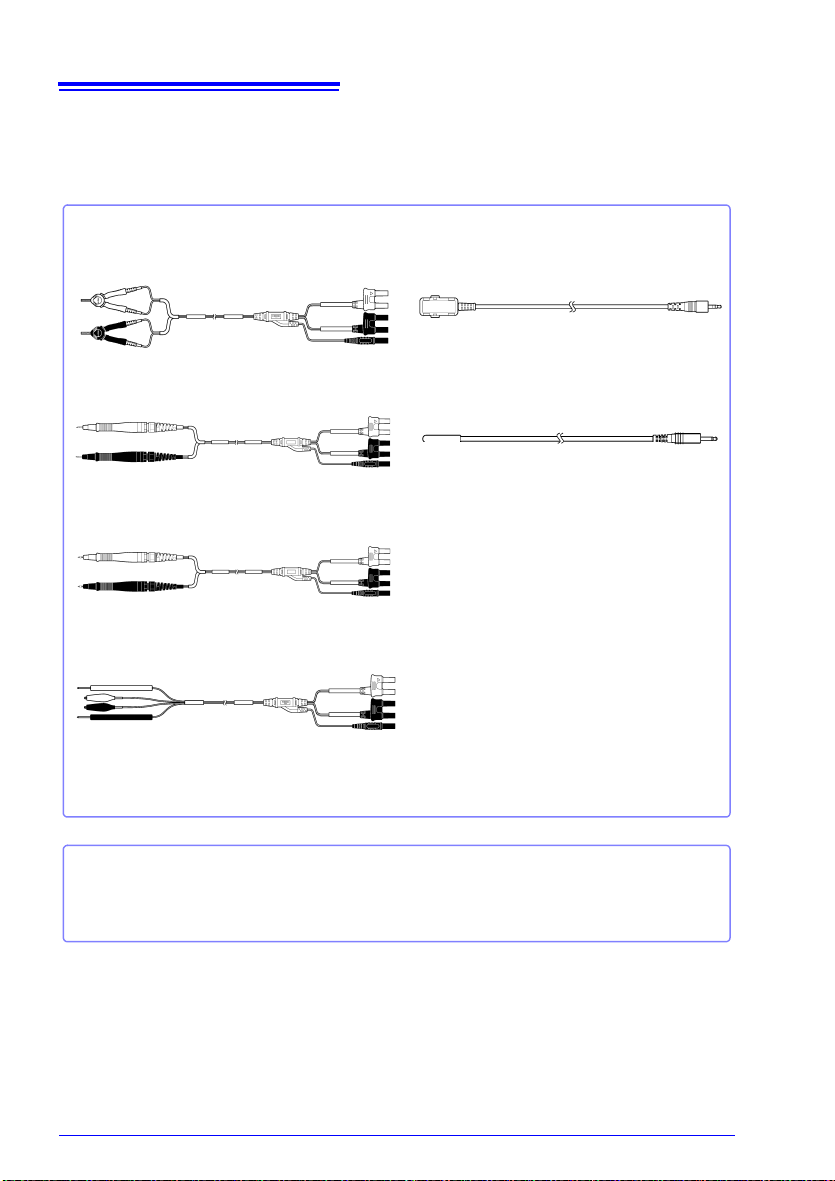
2
Measurement
Model L2101 Clip Type Lead
Model L2102 Pin Type Lead
Model L2103 Pin Type Lead
Model L2104 4-Terminal Lead
Interface Cables
Model 9637 RS-232C Cable (9pin-9pin/ 1.8 m/ crossover cable)
Model 9638 RS-232C Cable (9pin-25pin/ 1.8 m/ crossover cable)
Model L2105 LED Comparator Attachment
Model Z2001 Temperature Sensor
Verifying Package Contents
Options
Contact your authorized Hioki distributor or reseller for details.
See: "Appendix 14 Measurement Leads (Options)" (p. A28)
Page 11

Safety Information
Safety Information
This instrument is designed to conform to IEC 61010 Safety Standards, and has been thoroughly tested for safety prior to shipment.
However, using the instrument in a way not described in this manual may negate the provided safety features.
Before using the instrument, be certain to carefully read the following safety notes.
Mishandling during use could result in injury or death, as well as damage to the product. Be certain that you understand the instructions and
precautions in the manual before use.
With regard to the electricity supply, there are risks of electric shock,
heat generation, fire, and arc discharge due to short circuits. If persons
unfamiliar with electricity measuring instruments are to use the product, another person familiar with such instruments must supervise
operations.
This manual contains information and warnings essential for safe operation of the instrument and for maintaining it in safe operating condition. Before using it, be sure to carefully
read the following safety precautions.
Safety Symbols
3
In the manual, the symbol indicates particularly important information that the
user should read before using the instrument.
The symbol printed on the instrument indicates that the user should refer to a
corresponding topic in the manual (marked with the symbol) before using the
relevant function.
Indicates AC (Alternating Current).
Indicates the ON side of the power switch.
Indicates the OFF side of the power switch.
Indicates a fuse.
The following symbols in this manual indicate the relative importance of cautions and warnings.
Indicates that incorrect operation presents an extreme hazard that could result in
serious injury or death to the user.
Indicates that incorrect operation presents a significant hazard that could result in
serious injury or death to the user.
Indicates that incorrect operation presents a possibility of injury to the user or damage to the instrument.
Indicates advisory items related to performance or correct operation of the instrument.
Page 12
4
Safety Information
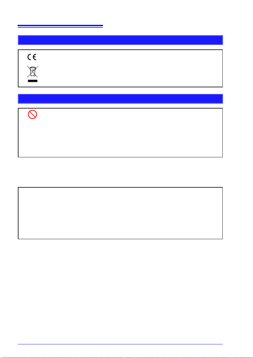
Symbols for Various Standards
Indicates that the product conforms to regulations set out by the EU Directive.
WEEE marking:
This symbol indicates that the electrical and electronic appliance is put on the EU
market after August 13, 2005, and producers of the Member States are required to
display it on the appliance under Article 11.2 of Directive 2002/96/EC (WEEE).
Other Symbols
Indicates the prohibited action.
(p. )
[ ]
SET
(Bold characters)
Accuracy
We define measurement tolerances in terms of f.s. (full scale), rdg. (reading) and dgt. (digit) values, with the
following meanings.
f.s.
rdg.
dgt.
See: "Example accuracy calculations" (p. 148)
Indicates the location of reference information.
*
Indicates that descriptive information is provided below.
Square brackets indicate instrument display labels (such as setting item names).
Bold characters within the text indicate operating key labels.
(maximum display value)
This is usually the name of the maximum displayable value. For this instrument, it
indicates the currently selected range.
(reading or displayed value)
The value currently being measured and indicated on the measuring instrument.
(resolution)
The smallest displayable unit on a digital measuring instrument, i.e., the input value
that causes the digital display to show a “1” as the least-significant digit.
Page 13
Operating Precautions
Operating Precautions
Follow these precautions to ensure safe operation and to obtain the full benefits of the various functions.
Preliminary Checks
Before using the instrument for the first time, verify that it operates normally to ensure that
no damage occurred during storage or shipping. If you find any damage, contact your
authorized Hioki distributor or reseller.
Before using the instrument, make sure that the insulation on the
power cord, leads or cables is undamaged and that no bare conductors
are improperly exposed. Using the instrument in such conditions could
cause an electric shock, so contact your authorized Hioki distributor or
reseller for replacements.
5
Page 14
6
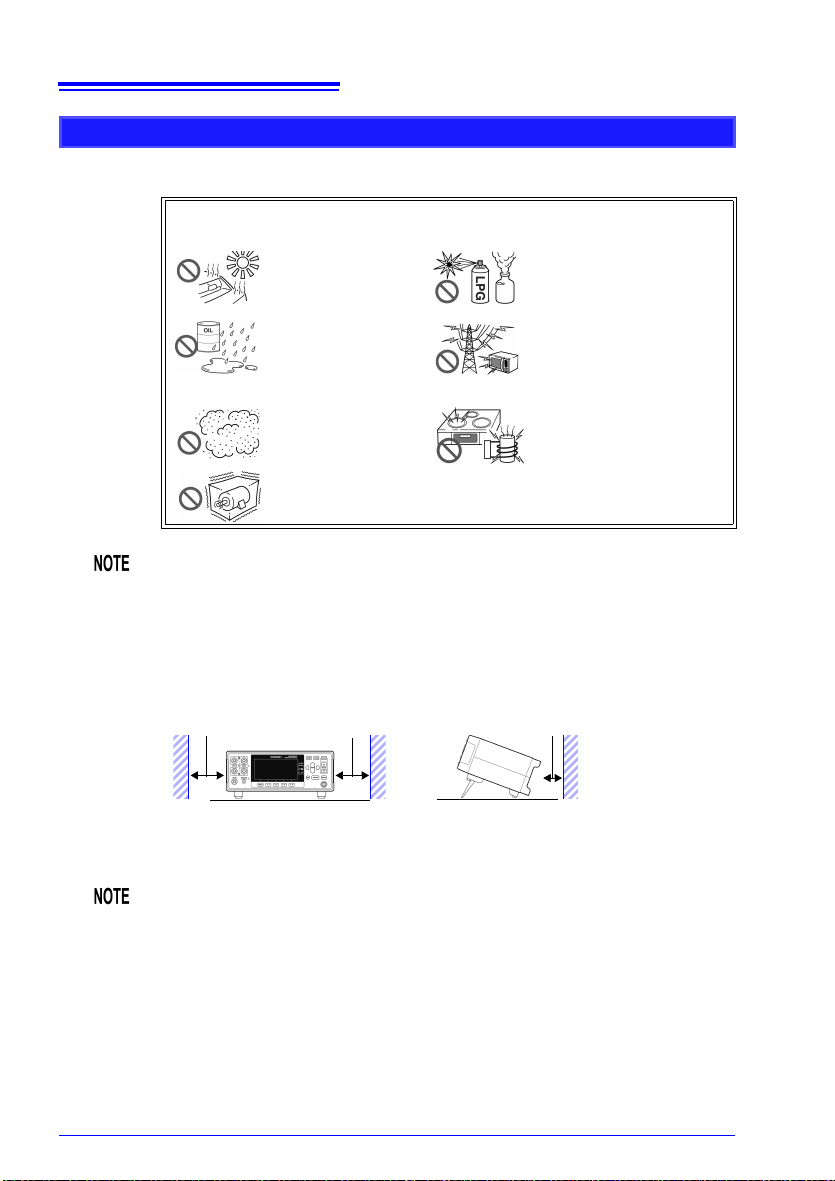
10 mm or more
Rear
50 mm or more 50 mm or more
The instrument can be used with the stand (p. 18).
It can also be rack-mounted. (p. A29).
Operating Precautions
Instrument Installation
Operating temperature and humidity : 0 to 40°C at 80% RH or less (non-condensating)
Storage temperature and humidity : -10°C to 50°C at 80% RH or less (non-condensating)
Avoid the following locations that could cause an accident or damage to the
instrument.
Correct measurement may be impossible in the presence of strong magnetic
fields, such as near transformers and high-current conductors, or in the presence of strong electromagnetic fields such as near radio transmitters.
Exposed to direct sunlight
Exposed to high temperature
Exposed to water, oil,
other chemicals, or solvents
Exposed to high humidity or condensation
Exposed to high levels
of particulate dust
Subject to vibration
In the presence of corrosive or
explosive gases
Exposed to strong electromagnetic fields
Near electromagnetic radiators
Near induction heating systems
(e.g., high-frequency induction heating systems and IH
cooking utensils)
Installation Precautions
• The instrument should be operated only with the bottom downwards.
• Do not place the instrument on an unstable or slanted surface.
Unplugging the power cord kills power to the instrument. Be sure to provide
enough unobstructed space to unplug the power cord immediately in an
emergency.
Page 15

Handling the Instrument
• Do not allow the instrument to get wet, and do not take measurements
with wet hands. This may cause an electric shock.
• Do not attempt to modify, disassemble or repair the instrument; as
fire, electric shock and injury could result.
• To avoid damage to the instrument, protect it from physical shock when
transporting and handling. Be especially careful to avoid physical shock
from dropping.
• To avoid damage to the instrument, do not apply voltage or current to mea-
surement terminals, TEMP.SENSOR jack, or COMP.OUT jack.
• This instrument may cause interference if used in residential areas. Such
use must be avoided unless the user takes special measures to reduce
electromagnetic emissions to prevent interference to the reception of radio
and television broadcasts.
• Use the original packing materials when transporting the instrument, if pos-
sible.
Handling the Cords and Leads
7
Operating Precautions
To avoid electrical shock, be careful to avoid shorting live lines with the
test leads.
• Avoid stepping on or pinching cables, which could damage the cable insula-
tion.
• To avoid breaking cables or lead wires, do not bend or pull them.
• To avoid damaging the power cord, grasp the plug, not the cord, when
unplugging it from the power outlet.
• To avoid damaging the cable, grasp the connector, not the cable, when
unplugging the cable.
• The ends of the pin type lead are sharp. Be careful to avoid injury.
• Keep the cables well away from heat sources, as bare conductors could be
exposed if the insulation melts.
• Temperature sensors are precision devices. Be aware that excessive volt-
age pulses or static discharges can destroy the film.
• Avoid subjecting the temperature sensor tip to physical shock, and avoid
sharp bends in the leads. These may damage the probe or break a wire.
• To avoid electric shock, do not exceed the lower of the ratings shown on the
instrument and test leads.
Page 16

8
Operating Precautions
• Use only the specified cords and leads. Using a non-specified cord or lead
may result in incorrect measurements due to poor connection or other reasons.
• If the part of the temperature sensor that connects to the instrument
becomes dirty, wipe it clean. The presence of dirt may affect temperature
measured values by increasing the contact resistance.
• Exercise care so that the temperature sensor connector does not become
disconnected. (If the sensor is disconnected, it will not be possible to perform temperature correction.)
CD-R disc precautions
• Exercise care to keep the recorded side of discs free of dirt and scratches.
When writing text on a disc’s label, use a pen or marker with a soft tip.
• Keep discs inside a protective case and do not expose to direct sunlight,
high temperature, or high humidity.
• Hioki is not liable for any issues your computer system experiences in the
course of using this disc.
Before Connecting the Power Cord
• To avoid electrical accidents and to maintain the safety specifications
of this instrument, connect the power cord provided only to a 3-contact (two-conductor + ground) outlet.
• Use only the designated power cord with this instrument. Use of other
power cords may cause fire.
• Before using the instrument, make sure that the insulation on the
power cord is undamaged and that no bare conductors are improperly
exposed. Any damage could cause electric shock, so contact your
authorized Hioki distributor or reseller.
To avoid damaging the power cord, grasp the plug, not the cord, when
unplugging it from the power outlet.
Before Connecting Measurement Leads
To avoid shock and short circuits, turn off all power before connecting
measurement leads.
Page 17

Before Connecting the LED Comparator Attachment
• To keep from damaging the instrument or LED Comparator Attachment,
turn off the instrument before connecting the attachment.
• The COMP.OUT jack is provided exclusively for use with the L2105. Do not
connect any device other than the L2105.
• The attachment may not fulfill the specifications if the connector is not
attached securely.
• Do not over-tighten the cable tie around the measurement leads. Doing so
may damage the measurement leads.
• Avoid the following as damage to the cable conductor or insulation may
result:
Twisting or pulling on cables
Bending cables near the lamp excessively in order to connect them
Before Connecting the Temperature Sensor
Failure to fasten the connectors properly may result in sub-specification performance or damage to the equipment.
Note the following precautions to avoid damaging the instrument:
• To keep from damaging the instrument or temperature sensor, turn off the
instrument’s main power switch before connecting the sensor.
• Connect the temperature sensor by inserting the plug all the way into the
TEMP.SENSOR jack. A loose connection can cause a large error component in measured values.
9
Operating Precautions
If the temperature sensor jack becomes dirty, wipe it clean. The presence of
dirt will cause an error in temperature measured values.
Page 18

10
Operating Precautions
Before Connecting Data Cables (USB, RS-232C)
Observe the following precautions when connecting the instrument and a
controller:
• To avoid faults, do not disconnect or reconnect the USB cable during instru-
ment operation.
• The USB and RS-232C interfaces are not isolated from the ground circuit.
Connect the instrument and the controller to a common earth ground.
Using different grounds could result in potential difference between the
instrument and the controller. Potential difference on the data cable can
result in malfunctions and faults.
• Before connecting or disconnecting the RS-232C Cable, always turn off the
instrument and the controller. Failure to do so could result in equipment
malfunction or damage.
• After connecting the RS-232C Cable, tighten the screws on the connector
securely. Failure to secure the connector could result in equipment malfunction or damage.
Before Connecting the Printer
Because electric shock and instrument damage hazards are present,
always follow the steps below when connecting the printer.
• Always turn off the instrument and the printer before connecting.
• A serious hazard can occur if a wire becomes dislocated and contacts
another conductor during operation. Make certain connections are
secure.
Page 19

Operating Precautions
Before Switching between Current Sink (NPN) and Current Source (PNP)
• Configure the NPN/PNP setting to accommodate externally connected
equipment.
• Do not operate the NPN/PNP switch while the instrument is on.
Before Connecting EXT I/O
To avoid electric shock or damage to the equipment, always observe
the following precautions when connecting to the EXT I/O connector.
• Always turn off the main power switch on the instrument and on any
devices to be connected before making connections.
• Be careful to avoid exceeding the ratings of external terminals (p.
106).
• During operation, a wire becoming dislocated and contacting another
conductive object can be serious hazard. Use screws to secure the
external connectors.
• The ISO_5V pin of the EXT I/O connector is a 5V (NPN)/ -5V (PNP)
power output. Do not apply external power to this pin. (External power
cannot be supplied to the instrument’s EXT I/O connector.)
11
To avoid damage to the instrument, observe the following cautions:
• Do not apply voltage or current to the EXT I/O terminals that exceeds their
ratings.
• When driving relays, be sure to install diodes to absorb counter-electromo-
tive force.
• Be careful not to short-circuit ISO_5V to ISO_COM.
• Configure the NPN/PNP setting to accommodate externally connected
equipment.
• Do not operate the NPN/PNP switch while the instrument is on.
See: "Connector Type and Signal Pinouts" (p. 91)
Before Turning Power On
Before turning the instrument on, make sure the supply voltage
matches that indicated on its power connector. Connection to an
improper supply voltage may damage the instrument and present an
electrical hazard.
Avoid using an uninterruptible power supply (UPS) or DC/AC inverter with
rectangular wave or pseudo-sine-wave output to power the instrument. Doing
so may damage the instrument.
Page 20

12
The measurement target is
connected to a power supply.
• Never attempt to measure at a point where volt-
age is present. Even if the power supply to the
motor is turned off, while the motor is rotating
inertially, high electromotive power is generated
in terminals. When attempting to measure a
transformer or motor immediately after voltage
withstanding test, induced voltage or residual
charge may damage the instrument.
Rotating inertially
• When the RM3544 is used in a way that connects to a withstanding voltage
tester via switching relays, construct a testing line bearing the following in
mind.
See: "Appendix 13 Using the Instrument with a Withstanding Voltage Tester" (p.
A27)
(1) The voltage withstanding specification of switching relays should
include a safe margin over the withstanding testing voltage.
(2) To protect against damage due to arc discharge in relay contacts, all
RM3544 measurement terminals should be grounded during voltage
withstanding testing.
(3) To protect against damage due to residual charge, measure resistance
first, and voltage withstanding last.
3158 AC Withstanding Voltage HiTester
Withstand voltage of relay switch is not high enough.
Residual charge from voltage
withstanding test is present.
RM3544
Operating Precautions
Before Measuring
• To avoid electric shock or damage to the
instrument, do not apply voltage to the
measurement terminals. Also, to avoid
electrical accidents, only take measurements after turning off the power to the
measurement targets being measured.
• Sparks may result at the moment the instrument is connected to, or
disconnected from, the measurement target. To avoid fire or bodily
injury, avoid use in the presence of explosive gases.
• Battery internal resistance cannot be measured with this instrument. It will
sustain damage. To measure battery internal resistance, we recommend the
HIOKI 3554, 3555, BT3562, BT3563 and 3561 Battery HiTesters.
Page 21

• When measuring devices such as power supply transformers with high
inductance or open-type solenoid coils, measured value may be unstable.
In such cases, connect a film capacitor of about 1 F between SOURCE A
and SOURCE B.
• Carefully insulate all SOURCE A, SENSE A, SENSE B, and SOURCE B
wiring. Proper 4-terminal measurements cannot be performed and an error
will occur if core and shield wires touch.
• The SOURCE terminal is protected by a fuse. If the fuse is tripped, the
instrument will display “
Blown Fuse.” and you will not be able to measure
resistance values. If the fuse is tripped, replace the fuse.
See: "12.2 Replacing the Measurement Circuit’s Protective Fuse" (p. 171)
When using the temperature sensor
The temperature sensor is not waterproof. Do not submerse it in water or
other liquid.
• Allow the measurement target for which temperature correction is being
performed and the temperature sensor to adjust to the ambient temperature
prior to measurement. Failure to do so will result in a large error component.
• Handling of the temperature sensor with bare hands may cause the sensor
to pick up inductive noise, resulting in unstable measured values.
• The temperature sensor is designed for use in applications in which ambi-
ent temperature is measured. It is not possible to accurately measure the
temperature of the measurement target itself by placing the sensor in contact with the surface of the target.
• Connect the temperature sensor by inserting the plug all the way into the
TEMP.SENSOR jack. A loose connection may cause a large error component in measured values.
13
Operating Precautions
Page 22

14
Operating Precautions
Page 23

15
• Installed footprint: 215 mm × 166 mm
Compact footprint and limited depth leave plenty of work space in front of the instrument.
• Measurement range: 30.000 m to 3.0000 M with a basic accuracy of 0.02%
rdg.
• Maximum measurement current: 300 mA
Ensures stable measurement, even when there is a significant amount of external noise.
• No need for warm-up operation or zero-adjustment
Since wasteful wait times are not required, you can start making measurements as soon as
the instrument is turned on.
• Choice of interfaces
RM3544 (no interface), RM3544-01 (USB, RS-232C, EXT I/O)
Compact yet reliable specifications
1.1 Product Overview and Features
Overview Chapter 1
1.1 Product Overview and Features
The RM3544 is capable of performing high-speed, high-precision measurement of the
winding resistance of components such as motors and transformers, the contact resistance
of relays and switches, the pattern resistance of printed circuit boards, and the DC resistance of fuses, resistors, and materials such as conductive rubber using four-terminal measurement. Since the instrument incorporates a temperature correction function, it is
particularly well suited to the measurement of targets whose resistance values vary with
temperature.
1
Page 24

16
LED Comparator Attachment (option)
Streamlines work by eliminating the need to look at the screen.
Graphical LCD
Operation is intuitive and easy to learn.
Easy configuration of comparator and panel
load operation
Facilitates smooth setup changes on production lines.
Simple basic settings
Range and measurement
speed can be set directly.
Guard terminal
You can reduce the
effects of external
noise by connecting the guard terminal.
Free power supply (100 to 240 V) with
automatic frequency switching
Allows the instrument to be easily moved to
overseas production lines.
Judgment sounds with user-selectable patterns
Keeps you from mistaking audio from a
nearby operator’s instrument as your own.
Easy-to-use functions in research and development,
on production lines, or in acceptance inspections
Monitor and test functions
Provides robust support for line development by allowing you to check
communications and EXT I/O on the
screen.
Example communications
monitor screen
Example EXT I/O test
screen
1.1 Product Overview and Features
Page 25

17
Display Screen (Monochrome graphical LCD)
Display of measurements and
settings (p. 21)
Viewing Measured
Values and Settings
COMP indicator LEDs
Indicate the judgment result of the measured value (p.60).
Hi Measured value is above upper limit
IN Pass (meets criteria)
Lo Measured value is below lower limit
Viewing Comparator Results
MENU key
Switching of F key pages
F keys
Selection of settings displayed
on the screen
COMP.OUT jack
Connect the L2105 LED Comparator Attachment to
view judgment results without needing to refer to the
instrument display. (p.70)
Connecting the LED Comparator Attachment
PANEL key
Saving and loading of panels
(p.72)
COMP key
Configuration of comparator
settings (p.60)
AUTO, RANGE key
Range switching (p.32)
SPEED key
Measurement speed switching
(p.33)
Cursor keys
Selection of settings and digits
ENTER key
Acceptance of settings and
manual trigger input
ESC key
Cancellation of operation
Settings
Measurement Terminals
Connect measurement leads (p. 26).
• SOURCE A : Current detection terminal
• SOURCE B : Current source terminal
• SENSE A : Voltage detection terminal
• SENSE B : Voltage detection terminal
• GUARD : Guard terminal
Connecting Measurement Leads
STANDBY Key: Initiates or cancels the
standby state. (p. 28).
• Unlit: power off (when no power supplied)
• Red light: Standby State (while power is supplied)
• Green light: power on
Initiating and Canceling the Standby State
1.2 Names and Functions of Parts
1.2 Names and Functions of Parts
Front Panel
1
Page 26
18
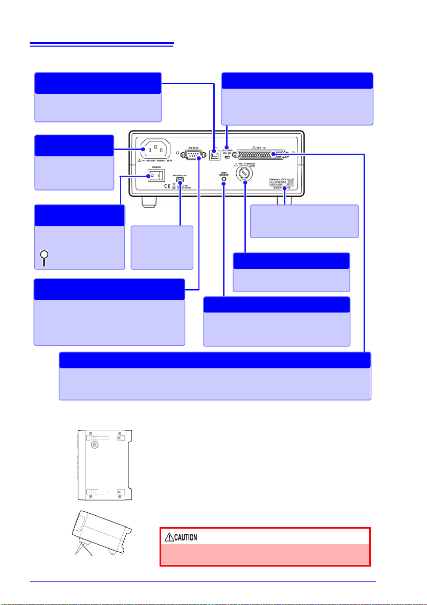
TEMP.SENSOR jack
Connect the Z2001 Temperature Sensor
when using temperature correction (p.27).
Correcting Temperature
RS-232C connector
• Connect to a computer, PLC, or other
device (p.126).
• Connect to a printer (p.137).
RS-232C Communications
Printer Output
Fuse holder (p.171)
Replacing the Fuse
Main power switch
(p.28)
: Main power off
: Main power on
Turning the Main
Power On and Off
EXT I/O connector
Connect when controlling the instrument with a PLC, I/O board, or other equipment to allow measurement to be started and measured values and comparator results to be acquired (p. 89).
External Control
Manufacturer's Serial No.
Do not remove this label, as it is
required for product support.
Power Inlet
Connect the supplied
power cord (p.25).
Connecting the
Power Cord
EXT I/O NPN/PNP switch
Left : Current sink (NPN)
Right : Current source (PNP)
Switching between NPN and PNP
USB jack
Connect to a computer (p.123).
Sending and Receiving
Data via USB
Maintenance
terminal
Do not use.
Bottom Panel
Stand
When using the stand
Extend the legs all the way. Do not extend partially.
Make sure to extend both legs of the stand.
Collapsing the stand
Do not collapse the stand partway. Be sure to collapse it
all the way.
This instrument can be rack mounted.
See: "Appendix 15 Rack Mounting" (p. A29)
Parts removed from this instrument should be stored
in a safe place to enable future reuse.
Do not apply heavy downward pressure with the
stand extended. The stand could be damaged.
1.2 Names and Functions of Parts
Rear Panel
Page 27

19
Install this instrument (p. 5)
1
Rear Panel
Turn on the instrument and cancel
the standby state
(p.28)
6
When finished measuring, turn the
power off (p.28).
Connect the temperature sensor
(p.27)
(When using the temperature correction function)
4
2
3
Make instrument settings
*1
Connect measurement leads (p.26)
7
Connect to the test sample (p.34)
8
Connect the power
cord (p.25)
Connect the external interface
(RM3544-01; as necessary)
5
• Using the printer (p.137)
• Using the USB or RS-232C inter-
face (p.121)
• Using the EXT I/O (p.89)
When clipping a small-gauge
wire
(Clip with the tip of the alligator
clips.)
When clipping a large-gauge
wire
(Clip with the back of the alligator
clips, where there are no teeth.)
6
3
4
2
5
Front Panel
Rear Front
1.3 Measurement Process
1.3 Measurement Process
1
Page 28

20
1.3 Measurement Process
*1 About zero-adjustment
Perform zero-adjustment in the following circumstances:
• The measured value is not cleared due to thermal EMF or other factors.
The measured value will be adjusted to zero. (Accuracy is not affected by whether or
not the zero adjustment is performed.)
• Four-terminal connection (called Kelvin connection) is difficult.
The residual resistance of the two-terminal connection wires will be canceled.
See: "4.1 Zero Adjustment" (p.44)
"Appendix 6 Zero Adjustment" (p.8)
Page 29
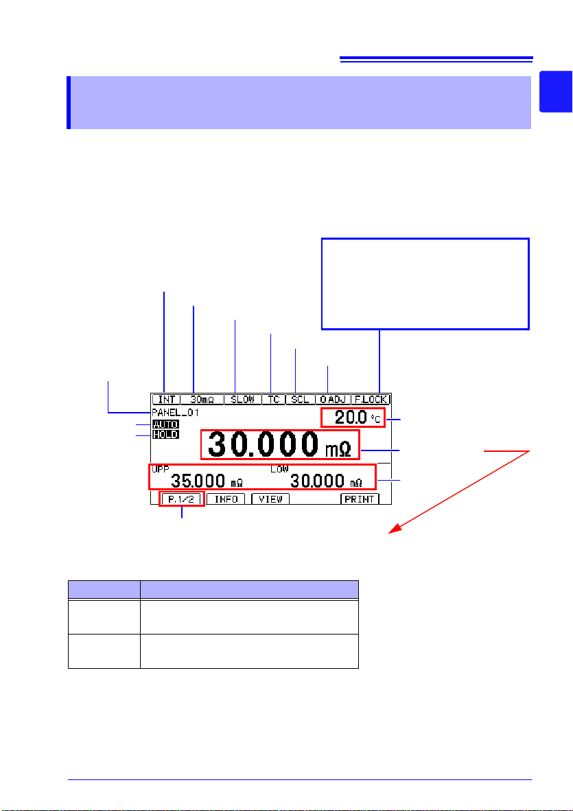
21
Trigger source (INT/EXT)
Measurement range
TC (ON)
0ADJ (ON)
Auto range
Key lock state or remote state
Cancel the key lock state or remote
state by pressing and holding the
MENU key.
F.LOCK : All operations prohibited.
M.LOCK: Menu operations prohibited.
RMT : Remote state
Judgment value
Switched with the VIEW key
(No display / temperature /
pre-calculation resistance
value)
Page switching
Measurement screen layout
Hold state
Scaling (ON)
Measurement speed
Number and name
of loaded panel
Measured value
1.4 Screen Organization and Operation Overview
1.4 Screen Organization and
Operation Overview
The instrument’s screen interface consists of a Measurement screen and various Settings
screens.
The screen examples in this guide appear reversed (black on white) for best visibility on the
printed page. However, the instrument screens can actually be displayed only as white
characters on black background.
1
Display of information other than measured values
(For more information, see "Confirming Measurement Faults" (p.38).)
* To treat current faults (when the source wiring is open) as over-range events, change the
Display Description
+OvrRng
-OvrRng
- - - - -
current fault output mode setting. (p.40)
Over-range
Not measured, or broken connection in measurement target *
Page 30
22
Overview of screen operation
Menu switching
(4) To Settings screens
(1) Measurement screen
(2) Comparator Settings screen
Upper limit
value
Lower limit
value
(3) Panel Save/Load screen
Select a panel number.
3
Change
values.
Move among
digits.
Accept the setting with the
key or cancel with the key.
4
Change the range with the
and keys.
2
1
2
Perform action with an F key.
1
Select the mode with an F key.
(4) Settings screen
< Setting values >
Make the value editable with the
key.
2
Change values.
1
Move among
digits.
Accept the setting with the key
or cancel with the key.
3
Return to the Measurement screen
with the key.
Move to the [MEAS], [SYS], [I/O],
or [IF] tab.
([I/O] and [IF] tabs: RM3544-01 only.
Not shown on RM3544.)
1
2
Select a
setting.
Move among
settings.
Switch functions with an F key or set
values.
3
4
1.4 Screen Organization and Operation Overview
Page 31

23
1.4 Screen Organization and Operation Overview
List of settings
Measurement screen COMP Comparator function (p.61)
Measurement screen
(P.1/2)
Measurement screen
(P.2/2)
Settings
screen
(SETTING)
*1 RM3544-01 only.
Screen Setting and key Overview See
PANEL Save/load panel (p.71)
Measurement
Settings screen
(MEAS)
System Settings
screen
(SYS)
EXT I/O Settings
screen
*1
(I/O)
Communication
Interface
Settings screen
*1
(IF)
AUTO
(RANGE)
SPEED Measurement speed (p.33)
INFO (F1) Display setting conditions
VIEW (F2)
PRINT (F4) Print
0 ADJ (F1) Zero-adjustment
LOCK (F2) Key lock
SETTING (F4) Switch to Settings screen
0 ADJUST Clear zero-adjustment (p.48)
TC SET Temperature correction (p.52)
AVERAGE Averaging (p.50)
AUTO HOLD Hold measured value (p.41)
COMP DELAY Judge delay (p.66)
SCALING(A∗R+B)
A:
B:
UNIT:
DIGITS Set the display digits (p.58)
CURR ERROR
MODE
KEY CLICK Set the operation sound (p.82)
COMP BEEP Hi
Lo
PANEL LOAD 0ADJ Load zero-adjustment values (p.74)
0ADJ RANGE Zero-adjustment range (p.47)
CONTRAST Set the contrast (p.83)
BACKLIGHT Set the contrast brightness (p.84)
POWER FREQ Set the power frequency (p.80)
RESET Reset the instrument (p.85)
ADJUST Adjust the instrument (p.A38)
TRIG SOURCE Set the trigger source (p.109)
TRIG EDGE Set the trigger signal logic (p.111)
TRIG/PRINT FILT Trigger/print filter function (p.113)
EOM MODE EOM signal setting (p.115)
JUDGE/BCD MODE EXT I/O output mode (p.117)
EXT I/O TEST Test EXT I/O (p.118)
INTERFACE Configure interface settings (p.123)
SPEED
CMD MONITOR
PRINT INTRVL
PRINT COLUMN
Measurement range
Switch measurement screen
display
Scaling (p.54)
Set the current fault output
mode
Set the judgment sound (p.68)IN
Communications (p.121)DATA OUT
Printing (p.137)
(p.32) (RANGE)
(p.139)
(p.44)
(p.78)
(p.40)
1
Page 32

24
1.4 Screen Organization and Operation Overview
Page 33
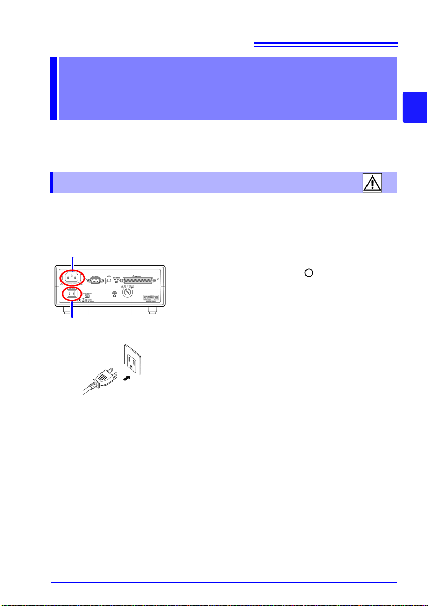
Measurement
Rear Panel
1 Confirm that the instrument's Main power
switch (rear panel) is OFF( ).
2 Confirm that the mains supply voltage matches
the instrument, and connect the power cord to
the power inlet on the instrument.
3 Plug the power cord into the mains outlet.
If power to the instrument is cut off with the power switch
in the ON position (by a circuit breaker, etc.), the instrument will start up when power is restored, without any
need to press the STANDBY key.
Power inlet
Main power switch
25
2.1 Connecting the Power Cord
Preparations
Be sure to read the "Operating Precautions" (p.5) before installing and connecting this
instrument.
Refer to "Appendix 15 Rack Mounting" (p. A29) for rack mounting.
Chapter 2
2.1 Connecting the Power Cord
Turn off the power before disconnecting the power cord.
2
Page 34
26
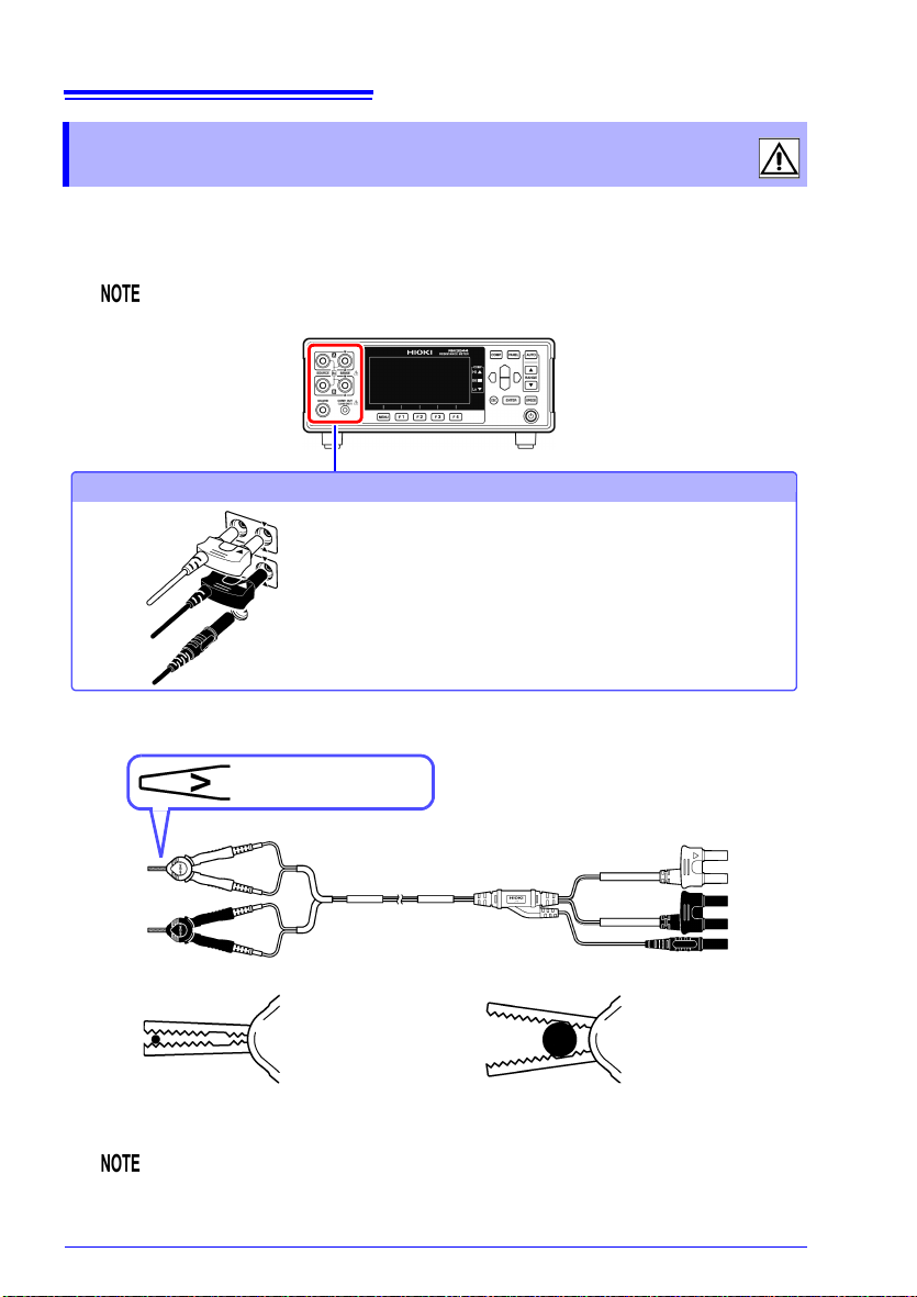
Connection Methods
Connecting measurement leads
Connect the red plugs to the SOURCE A and
SENSE A terminals, the black plugs to the
SOURCE B and SENSE B terminals, and the
guard plug to the GUARD terminal.
When clipping a small-gauge wire
(Clip with the tip of the alligator clips.)
When clipping a large-gauge wire
(Clip with the back of the alligator clips, where
there are no teeth.)
Measurement leads
(Example: When using the L2101 Clip Type Lead)
SENSE
SOURCE
The “V” mark indicates
the SENSE side.
SENSE
SOURCE
Red
Black
SENSE
SOURCE
SENSE
SOURCE
Red
Black
Red plugs
Black plugs
Guard plug
2.2 Connecting Measurement Leads
2.2 Connecting Measurement Leads
Connect the included or optional Hioki measurement leads to the measurement terminals.
Before connecting the measurement leads, read "Operating Precautions" (p.5) carefully.
Refer to "Options" (p.2) for details.
We recommend using optional Hioki measurement leads.
When making your own measurement leads or extending a measurement
lead, see "Appendix 11 Making Your Own Measurement Leads" (p. A24).
Page 35
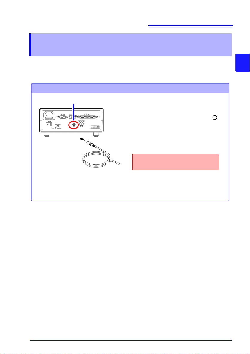
2.3 Connecting Z2001 Temperature Sensor (When using the TC)
Connection Methods
Connecting the Z2001 Temperature Sensor
Rear Panel
Z2001 Temperature Sensor
TEMP.SENSOR jack
Insert the plug securely all the way
into the jack.
1 Confirm that the instrument's Main
power switch (rear panel) is OFF( ).
2 Plug the Z2001 Temperature Sensor
into the TEMP.SENSOR jack on the rear
panel.
3 Place the tip of the temperature sensor
near the measurement target.
2.3 Connecting Z2001 Temperature Sensor
(When using the TC)
27
Before connecting the temperature sensor, read "Operating Precautions" (p.5) carefully.
2
Page 36

28
Turn on ( ) the main power switch on the rear of the
instrument.
If the main power switch was turned off while the
instrument was not in the standby state, the standby
state will be automatically canceled when the main
power switch is turned on.
Power ON
Turn off ( ) the main power switch on the rear of the
instrument.
Power OFF
Press the STANDBY key (the STANDBY
key will change from red to green).
2.4 Turning the Power On and Off
2.4 Turning the Power On and Off
Turning On the Instrument with the Main Power Switch
Turning Off the Instrument with the Main Power Switch
Canceling the Standby State
Page 37

2.4 Turning the Power On and Off
Self-test
Indicates an error (p. 169).
After the standby state is canceled, a self-test (instrument diagnostic routine) is performed.
During the self-test, the following information is displayed while the hardware is verified.
Error
No Errors
Normal display (measurement screen)
The following information is displayed during self-testing:
• Manufacturer and model name
• Firmware versions
• Communication interface setting
• Detected line frequency
• EXT I/O (NPN/PNP) setting
When powered up for the first time, the default settings appear.
See: "Default Settings" (p.87)
29
2
Before Starting Measurement
The SOURCE terminal is protected by a fuse. If the fuse is tripped, the instrument will display “Blown FUSE.” and you will not be able to measure resistance values. In this case,
replace the fuse.
See: "12.2 Replacing the Measurement Circuit’s Protective Fuse" (p.171)
Measurement settings are recalled from when the power was previously turned off (settings
backup).
Placing the Instrument in the Standby State
Press the Standby key (the Standby key will change from green to red).
Disconnect the power cord from the outlet to extinguish the standby key light.
When power is turned on again, operation resumes with the same state as when last turned
off.
If a power outage (e.g., breaker trip) occurs when the instrument is on, it will automatically
turn on again when power is restored (without pressing the standby key).
Page 38

30
Do not use the instrument if
damage is found, as electric
shock or short-circuit accidents
could result. Contact your authorized Hioki distributor or reseller.
Metal Exposed
Is the power cord insulation torn, or
is any metal exposed?
1
Before using the instrument for the first time, verify that it operates normally to
ensure that no damage occurred during storage or shipping. If you find any damage, contact your authorized Hioki distributor or reseller.
Peripheral Device Inspection
Is the insulation on a measurement
lead torn, or is any metal exposed?
No Metal Exposed
If there is any damage, measured
values may be unstable and
measurement errors may occur.
Replace the cable with an undamaged one.
Metal Exposed
No Metal Exposed
If damage is evident, request repairs.
Yes
Is damage to the instrument evident?
Instrument Inspection
When turning power on
Is the STANDBY key red or green?
No
2
The power cord may be damaged, or the instrument may be
damaged internally. Request repairs.
After the completion of the self-test
(when the model number is shown
on the screen), is the Measurement screen displayed?
No
Yes
The instrument may be damaged
internally. Request repairs.
See: "12.1 Troubleshooting" (p. 160)
"Error Displays and Remedies"
(p.169)
An error indication
occurs
Yes
Inspection complete
2.5 Pre-Operation Inspection
2.5 Pre-Operation Inspection
Page 39

Basic Measurements
Chapter 3
31
Before making measurements, read "Operating Precautions" (p. 12) carefully.
This chapter explains basic operating procedures for the instrument.
"3.1 Selecting the Measurement Range" (p.32)
"3.2 Setting the Measurement Speed" (p.33)
"3.3 Connecting Measurement Leads to the Measurement Target" (p.34)
"3.4 Checking Measured Values" (p.35)
To customize measurement conditions, see "Chapter 4 Customizing Measurement Conditions" (p.43).
3
Page 40
32
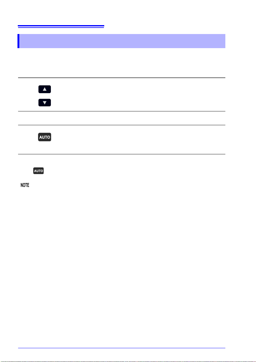
Select the range to use. (AUTO off)
The decimal point location and unit indicator change with each
key press.
Press this while a manual range is selected. (AUTO lights)
The optimum measurement range is automatically selected.
3.1 Selecting the Measurement Range
3.1 Selecting the Measurement Range
The measurement range can be set as follows. Auto-ranging (the AUTO range) can also be
selected.
Manual Range Setting
Auto-Ranging
Switching from Autoranging back to Manual range selection
Press again. The range can now be changed manually.
• When the comparator function is turned ON, the range cannot be changed from fixed (it
cannot be switched to auto-ranging). To change the range, turn OFF the comparator
function or change the range from within the comparator settings.
• When measuring certain motor, transformer or coil components, the auto range setting
may not stabilize. In such cases, use manual range selection.
• The measurement target power is given by (resistance value × (measurement current)
if the measured value is within the measurement range. If the measurement range is
exceeded, the power may reach a maximum value that is given by (open voltage × measurement current). Check the measurement range before connecting the measurement
target.
A rush current of up to 500 mA will flow at the moment the instrument is connected to the
measurement target.
(Convergence time: For pure resistance, approximately 1 ms)
• Refer to "Resistance Measurement Accuracy" (p. 146) for information on each range
measurement accuracy.
2
)
Page 41

33
Press this to change the measurement speed.
Measurement speed
FAST
MEDIUM SLOW
50 Hz 60 Hz
Measurement time 21 ms 18 ms 101 ms 401 ms
With TC ON, comparator ON, and error of ±10%±2 ms
Integration time (detected voltage data acquisition time) reference values
FAST (50 Hz): 20.0 ms, FAST (60 Hz): 16.7 ms, MEDIUM: 100 ms, SLOW: 400 ms
3.2 Setting the Measurement Speed
3.2 Setting the Measurement Speed
The measurement speed can be set to FAST, MED (medium), or SLOW.
The MED (medium) and SLOW settings offer increased measurement precision compared
to the FAST setting as well as greater resistance to the effects of the external environment.
If the setup is excessively susceptible to the effects of the external environment, shield the
measurement target and measurement leads adequately and twist the cables together.
See: "Appendix 7 Unstable Measured Values" (p.13)
Relationship Between Measurement Range and Speed
3
Page 42
34
(Place leads in contact with target.)
SOURCE A SENSE A SENSE B SOURCE B
The SENSE terminals are placed to the inside of the SOURCE terminals.
3.3 Connecting Measurement Leads to the Measurement Target
3.3 Connecting Measurement Leads to the Measurement Target
Before making measurements, read "Operating Precautions" (p.5) carefully.
Example with L2101
Example with L2102
Example with L2104
Page 43

35
The resistance value will be displayed.
• If the display does not indicate the mea-
sured value, see "Confirming Measurement Faults" (p. 38).
• To convert the value into a parameter
other than resistance, see below.
See: "4.4 Correcting Measured Values and
Displaying Physical Properties Other than
Resistance Values (Scaling Function)"
(p.54)
[VIEW]
Switch the Measurement
screen.
Switch the function menu
to P.1/2.
1
2
You can switch this part of the display to
show nothing, the temperature, or the precalculation measured value.
See: "Example displays" (p.36)
3.4 Checking Measured Values
3.4 Checking Measured Values
When measuring close to 0 , measured values may turn negative. If measured values turn
negative otherwise, check the following:
• Are the SOURCE or SENSE wires connected backwards?
Rewire correctly.
• Has the contact resistance decreased since you performed zero-adjustment?
Repeat the zero-adjustment process.
• Is the scaling calculation result negative?
Change the scaling settings.
3
Switching the Display
You can change what information is shown on the Measurement screen.
Displaying temperature and pre-calculation measured values
Page 44

36
(No display) (Temperature display)
Rt: Resistance measured value
before TC calculation
R: Resistance measured value
before scaling
(Value before REF% calculation
: With REF% comparator setting and
scaling OFF)
(Value before REF% calculation
: With REF% comparator setting and
scaling ON)
(Value before TC calculation
: With TC ON)
(Value before scaling calculation
: With scaling ON)
R: Resistance measured value
(before relative calculation)
RS: Resistance measured value
after scaling (before relative calculation)
3.4 Checking Measured Values
Example displays
Display of pre-calculation measured values varies with the settings.
Page 45
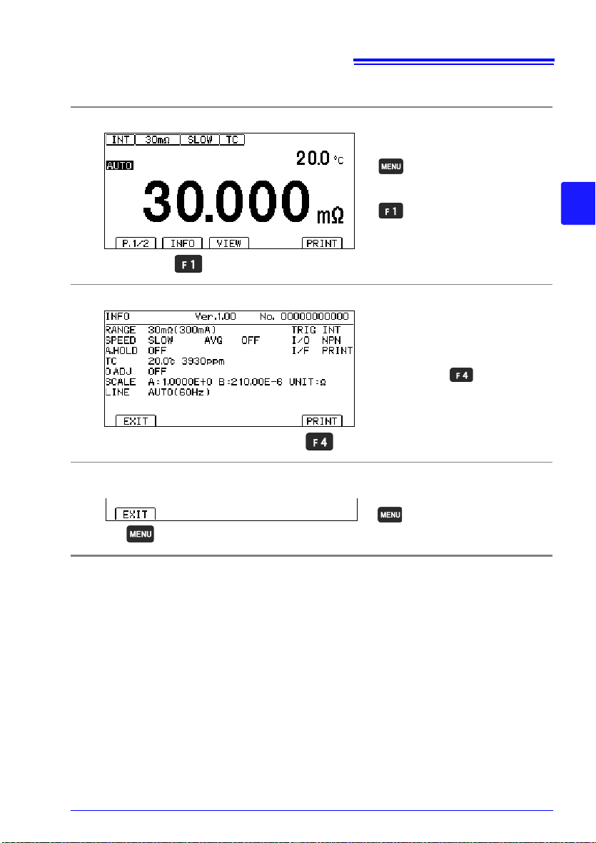
3.4 Checking Measured Values
[INFO]
Display measurement
conditions.
Switch the function menu
to P.1/2.
1
2
If the interface type has been
set to "printer," you can print
settings with .
Return to the
Measurement screen.
Displaying a list of measurement conditions and settings
Display the measurement conditions.
1
Check the measurement conditions.
2
37
3
Return to the Measurement screen.
3
Page 46

38
This fault is displayed in the following two instances.
(1) Appears when the measured value is outside of the measurement or display range. (*1)
(2) Appears when a measurement fault(*2) occurs (when the current fault mode setting is
“Over-range”).
When no measurement current flows from the SOURCE A terminal to the SOURCE B
terminal
Similarly, if the measurement range is exceeded in temperature measurement, OvrRng is
displayed.
The comparator result is Hi when +OvrRng is displayed, and Lo when -OvrRng is displayed. No ERR signal is output.
Over-range
+OvrRng
-OvrRng
Display
- - - - -
Current Fault or measurement not performed
This fault is displayed in the following instances. If “- - - - -” is displayed, a comparator judgment will not be made.
(1) Appears when a measurement fault(*2) occurs (when the current fault mode setting is
“Current fault”).
When no measurement current flows from the SOURCE A terminal to the SOURCE B
terminal
(2) This fault is displayed when no measurement has been performed since the measure-
ment conditions were changed.
Display
Temperature measurement cannot be performed because the temperature sensor has not
been connected. There is no need to connect the temperature sensor when not using temperature correction. Switch the display if you do not wish to display the temperature.
See: "Switching the Display" (p.35)
- - . - °C
Temperature sensor not connected
Display
Current fault mode setting (p. 40)
Current fault Over-range
Display: - - - - COMP indicator: No judgment
EXT I/O: ERR signal output, no HI signal output
Display: +OvrRng
COMP indicator: Hi
EXT I/O: No ERR signal output, HI signal output
3.4 Checking Measured Values
Confirming Measurement Faults
When a measurement is not performed correctly, a measurement fault indicator appears
and a ERR signal of the EXT I/O is output (no ERR signal is output for over-range or
unmeasured events). Operation when a current fault occurs can be changed with the settings.
An unstable measured value may be displayed if the SOURCE terminal is connected to the
measurement target but the SENSE terminal has poor contact.
Example displays: Display and output when the probes are open or when the measurement target is open
Page 47
*1 Over-range Detection Function
Examples of Over-range Faults
Over-range Detection Measurement Example
The measured value is outside of
the measurement range.
The relative tolerance (%) display
of the measured value exceeds
the display range (999.99%).
The zero-adjusted value is outside of the display range.
While measuring, input voltage
exceed the A/D converter input
range.
Current did not flow normally to
the measurement target.
(When the current fault mode setting is set to “Over-range output”
only)
Attempting to measure 40 m with the 30 m range selected
Measuring 500 (+2400%) with a reference value of 20
Performing zero-adjustment after connecting 50 m with the 300 m
range
Measuring 10 m yields a -40 m reading, exceeding the display
range.
Measuring a large resistance value in an electrically noisy environment
When the measurement target yields an open FAIL result
When either the SOURCE A or SOURCE B terminal suffers from poor
contact.
*To display “- - - - -” when a current fault occurs, set the current fault
mode setting to “Current fault.”(p.40)
*2 Current Fault Detection Function
Example of Current Fault
• SOURCE A or SOURCE B probe open
• Broken measurement target (open work)
• SOURCE A or SOURCE B cable break, poor connection
39
3.4 Checking Measured Values
3
• SOURCE wiring resistance in excess of the following values may cause a current fault,
making measurement impossible. When using measurement current 300 mA ranges,
keep the wiring resistance as well as the contact resistance between the measurement
target and measurement lead low.
(Reference value)
Range
30 m, 300 m 2
3 70
30 100
300 2 k
3 k 700
30 k to 3 M 2 k
• If a measurement is performed using a high-resistance range, it will take time after the
Wiring resistance and contact resistance
(Resistance value between SOURCE B and SOURCE A,
excluding measurement target)
probes are actually open until a constant current error occurs.
Example:300 k range 20 ms
3 M range 250 ms
Page 48

40
The Settings screen
appears.
Switch the function menu
to P.2/2.
1
2
Move the cursor to the
[MEAS] tab with the left and
right cursor keys.
2
Current fault (default)
Over-range
Selection
1
Return to the
Measurement screen.
3.4 Checking Measured Values
Setting the measurement method for an open target (current fault mode
setting)
This section describes how to configure instrument operation when current fault output is
detected.
When set to current fault, a break in the measurement target wiring is determined to be an
error, and no comparator judgment is made. When set to over-range, a break in the measurement lead or other open state is determined to be an over-range event, and a comparator judgment of Hi results. Choose the setting that best suits your application.
Open the Settings Screen.
1
Open the Measurement Settings Screen.
2
Select the desired current fault mode.
3
Return to the Measurement screen.
4
Page 49
41
The Settings screen
appears.
Switch the function menu
to P.2/2.
1
2
Move the cursor to the
[MEAS] tab with the left and
right cursor keys.
2
ON
OFF (default)
Selection
1
Return to the
Measurement screen.
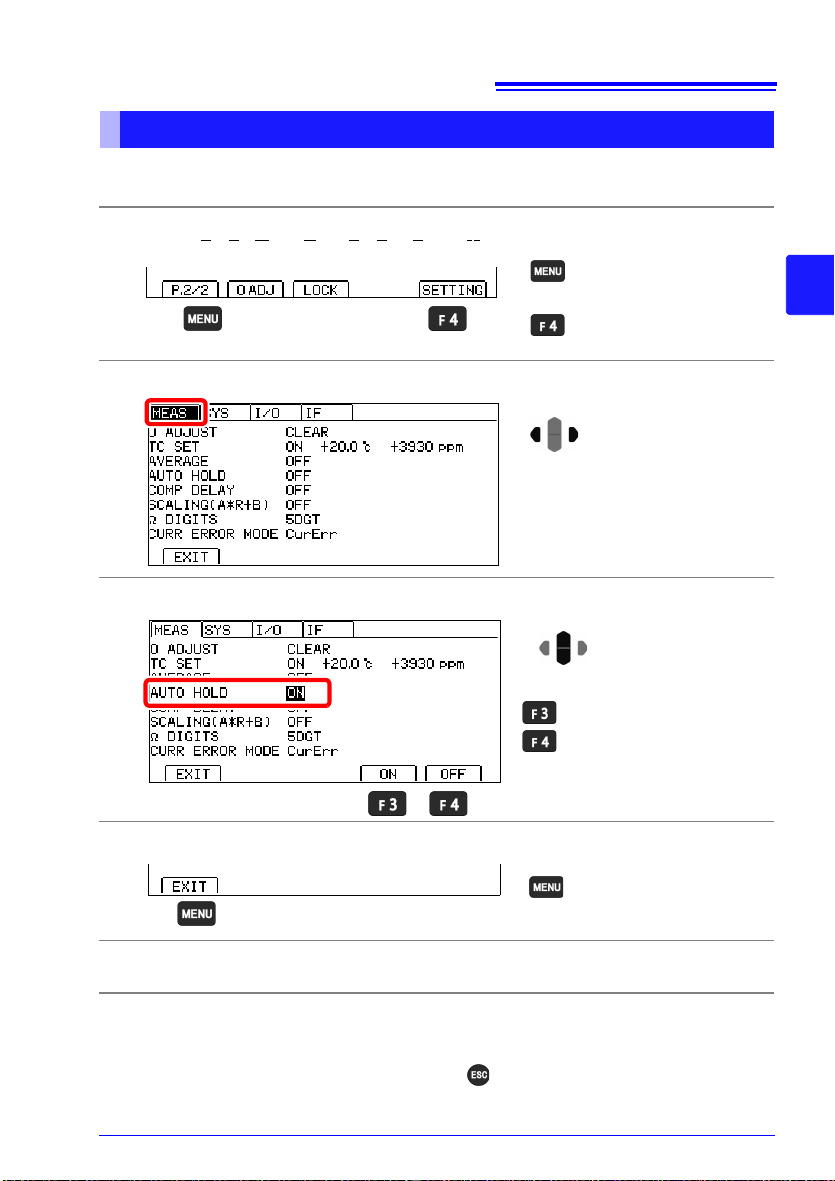
3.4 Checking Measured Values
Holding Measured Values
The auto-hold function provides a convenient way to check measured values. Once the
measured value stabilizes, the beeper will sound, and the value will be automatically held.
Open the Settings Screen.
1
Open the Measurement Settings Screen.
2
Enable the auto-hold function.
3
3
Return to the Measurement screen.
4
While the measured value is being held, the HOLD indicator will light up.
5
Canceling auto-hold operation
Hold operation is automatically canceled when the measurement leads are removed from
the measurement target and then brought into contact with the measurement target again.
You can also cancel hold operation by pressing or changing the range and measurement speed. When hold operation is canceled, the HOLD indicator will go out.
Page 50

42
3.4 Checking Measured Values
Page 51

Customizing Measurement
43
Conditions
Before making measurements, read "Operating Precautions" (p. 12) carefully.
This chapter explains functionality employed to make more advanced, more accurate measurements.
"4.1 Zero Adjustment" (p. 44)
"4.2 Stabilizing Measured Values (Averaging Function)" (p. 50)
"4.3 Correcting for the Effects of Temperature (Temperature Correction
(TC))" (p. 52)
"4.4 Correcting Measured Values and Displaying Physical Properties Other
than Resistance Values (Scaling Function)" (p. 54)
"4.5 Changing the Number of Measured Value Digits" (p. 58)
Chapter 4
4
Page 52

44
4.1 Zero Adjustment
4.1 Zero Adjustment
Perform zero-adjustment in the following circumstances:
• The measured value is not cleared due to thermal EMF or other factors.
The measured value will be adjusted to zero. (Accuracy is not affected by whether or
not the zero adjustment is performed.)
• Four-terminal connection (called Kelvin connection) is difficult.
The residual resistance of the two-terminal connection wires will be canceled.
For more information about how to perform zero-adjustment properly, see "Appendix 6 Zero
Adjustment" (p. A8).
Before Zero Adjustment
• Execute zero adjustment when the ambient temperature has changed, or when a mea-
surement lead is replaced after zero adjustment was performed. However, when performing zero-adjustment is difficult, for example when using the L2102 or L2103 Pin Type
Lead, perform zero-adjustment using the standard included L2101 Clip Type Lead or similar lead and then switch to the pin type lead to perform measurement.
• Zero adjustment should be executed in each range to be used. Perform zero-adjustment
for the current range only when setting the range manually or for all ranges when using
auto-ranging.
• Zero adjustment values are retained internally even when the instrument is turned off.
They are also saved with panels. You can also elect not to load zero-adjustment values
from panels.
See: "6.1 Saving Measurement Conditions (Panel Save Function)"(p.72)
"6.2 Loading Measurement Conditions (Panel Load Function)"(p.73)
• Zero-adjustment can be performed even when the EXT I/O 0ADJ signal is ON (when
shorted with the EXT I/O connector’s ISO_COM pin).
• Although resistance of -3%f.s. to 50%f.s. can be canceled in each range, try to keep the
canceled resistance to 3%f.s. (f.s.=30,000dgt.) The zero-adjustment range can be
changed to TIGHT (-3%f.s. to 3%f.s.).
See: "Changing the zero-adjustment range" (p. 47)
• If a resistance that is smaller than the resistance value when zero-adjustment was per-
formed is measured, the measured value will be negative.
Example: If you set an offset of 20 m for the 300 m range
If you measure 10 m, -10 m will be displayed.
Page 53

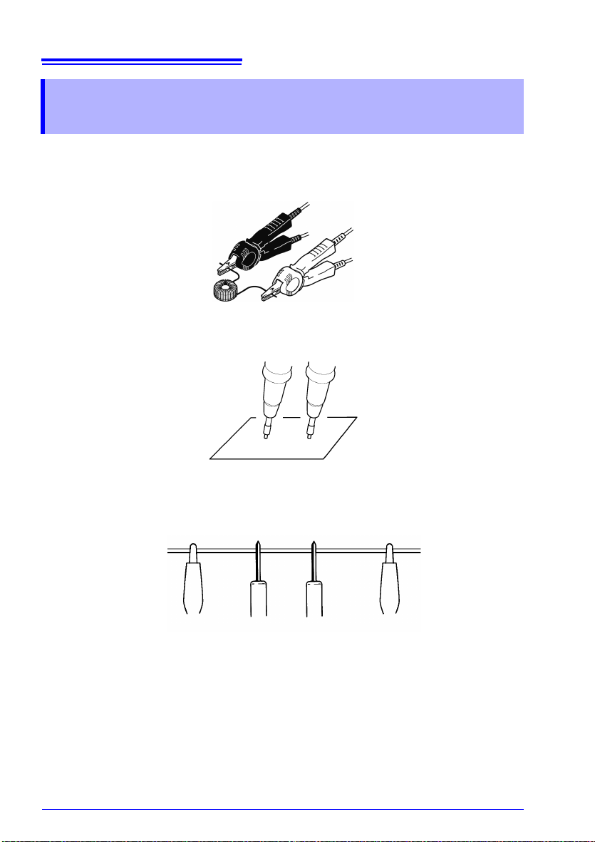
Performing zero-adjustment
Red
SOURCE
SOURCE
SOURCE
SENSE
SENSE
SENSE
Red
Black
Black
SOURCE
SENSE
Bring the "V" marks together
at the same position.
Connection
Connection
SENSE A SENSE B
SOURCE A SOURCE B
L2104 (option)
L2101
L2102, L2103 (options)
Since zero-adjustment cannot be performed with the L2102 or L2103,
use the L2101 Clip Type Lead or other lead type to perform zero-adjustment.
Place the alligator clips on the outside
and the lead rods on the inside when
performing zero-adjustment.
Correct
Incorrect
Short the measurement leads together.
1
45
4.1 Zero Adjustment
4
Page 54

46
Proper wiring Improper wiring
[0ADJ]
Perform zero-adjustment.
Switch the function menu
to P.2/2.
1
2
Perform zero-adjustment
and return to the Measurement screen.
Cancel the operation and
return to the previous
screen.
4.1 Zero Adjustment
Verify that the measured value is within ±3%f.s. If the zero-adjustment range
2
is set to NORMAL (-3%f.s. to 50%f.s.), zero-adjustment can be performed
when the measured value is 50%f.s. or less in each range, but a warning will
be issued when it is greater than 3%f.s.
If no measured value is displayed, verify whether the measurement leads
have been wired properly.
Perform zero-adjustment.
3
A confirmation message will be displayed. Confirm and return to the Mea-
4
surement screen.
Page 55

Zero Adjustment Faults
The Settings screen
appears.
Switch the function menu
to P.2/2.
1
2
Move the cursor to the [SYS]
tab with the left and right cursor keys.
If zero adjustment fails, the following error message appears.
47
4.1 Zero Adjustment
Before attempting zero adjustment again, confirm the following:
• Verify that the measured value is within each range (NORMAL: -3%f.s. to 50%f.s.,
TIGHT: -3%f.s. to 3%f.s.).
• When using measurement leads that you made, reduce the wiring resistance.
• Confirm that the measurement leads connections are correct.
See: "*2 Current Fault Detection Function" (p. 39)
• If zero-adjustment fails for auto-ranging, zero-adjustment will be canceled for all ranges.
• If zero-adjustment fails for a manually set range, zero-adjustment will be canceled for the
current range.
Changing the zero-adjustment range
Although the default setting of the zero-adjustment range is -3%f.s. to 50%f.s. (the warning
will be issued when the value is more than 3%f.s.), the zero-adjustment range can be
changed to the setting that a value exceeding 3%f.s. results in an error without issuing any
warning.
Open the Settings Screen.
1
Open the System Setting Screen.
2
4
Page 56

48
2
Range: -3%f.s. to 3%f.s.
Range: -3%f.s. to 50%f.s.
(default)
Selection
1
Return to the
Measurement screen.
The Settings screen
appears.
Switch the function menu
to P.2/2.
1
2
Move the cursor to the
[MEAS] tab with the left and
right cursor keys.
4.1 Zero Adjustment
Select the zero-adjustment range setting function to be TIGHT.
3
Return to the Measurement screen.
4
The changed setting will be applied to the zero-adjustment that will be performed after the
setting is changed. The zero-adjustment that has been already performed and panel-saved
remains effective. Perform zero-adjustment again as necessary.
Canceling zero-adjustment
Cancels zero-adjustment for all ranges.
Open the Settings Screen.
1
Open the Measurement Settings Screen.
2
Page 57

Select 0 ADJUST.
2
Cancel zero-adjustment.
Selection
1
Clear zero-adjustment and
return to the Settings
screen.
Cancel the operation and
return to the previous
screen.
Return to the
Measurement screen.
3
49
4.1 Zero Adjustment
A confirmation message will be displayed. Confirm and return to the Mea-
4
surement screen.
Return to the Measurement screen.
5
4
Page 58

50
The Settings screen
appears.
Switch the function menu
to P.2/2.
1
2
Move the cursor to the
[MEAS] tab with the left and
right cursor keys.
Enables the averaging
function
Disables the averaging
function (default) (go to
step 5)
Selection
2
1
4.2 Stabilizing Measured Values (Averaging Function)
4.2 Stabilizing Measured Values
(Averaging Function)
The averaging function averages multiple measured values and displays the results. It can
be used to reduce variation in measured values.
For internal trigger measurement (Free-Run), a moving average is calculated.
For external trigger measurement (and :READ? command operation) (Non-Free-Run), a
mean average is used.
For more information about communications commands, see the included application disc.
Average (of measurements D1 to D6) with Averaging Samples set to 2.
1st Sample 2nd Sample 3rd Sample
Free-Run (Moving Avg.) (D1+D2)/2 (D2+D3)/2 (D3+D4)/2
Non-Free-Run (Mean Avg.) (D1+D2)/2 (D3+D4)/2 (D5+D6)/2
Open the Settings Screen.
1
Open the Measurement Settings Screen.
2
Enable the averaging function.
3
Page 59

Set the number of averaging iterations.
Move the cursor to the setting you
wish to configure. Make the value
editable with the key.
2
Move the cursor to the digit you
wish to set with the left and right
cursor keys. Change the value
with the up and down cursor keys.
Change
values.
1
Move among
digits.
Setting range: 2 to 100 times (default: 2 times)
3
Accept
( Cancel)
Return to the
Measurement screen.
4
Return to the Measurement screen.
5
51
4.2 Stabilizing Measured Values (Averaging Function)
4
Page 60
52
The Settings screen
appears.
Switch the function menu
to P.2/2.
1
2
Move the cursor to the
[MEAS] tab with the left and
right cursor keys.
2
Enables the TC function
Disables the TC function
(default) (go to step 5)
Selection
1
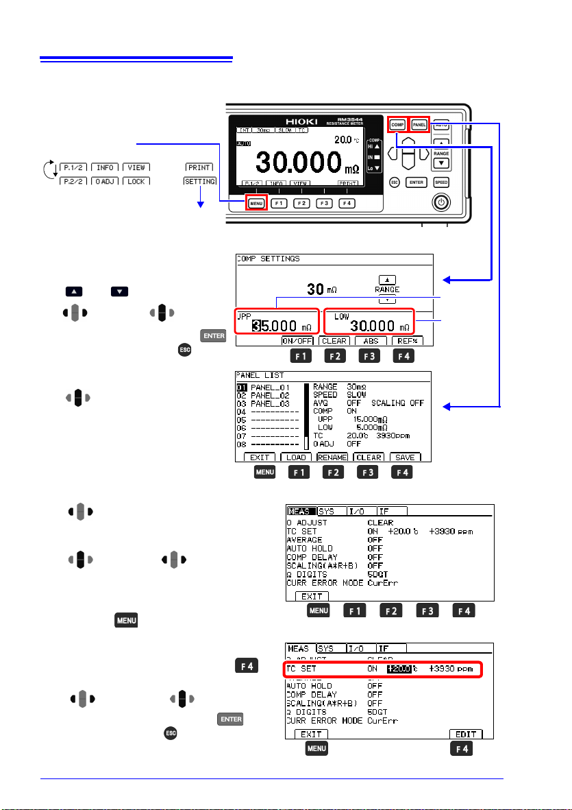
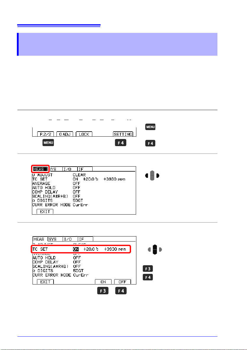
4.3 Correcting for the Effects of Temperature (Temperature Correction (TC))
4.3 Correcting for the Effects of Temperature
(Temperature Correction (TC))
Temperature correction converts resistance values to resistance values at standard temperature and displays the result.
For more information about the principle of temperature correction, see "Appendix 4 Tem-
perature Correction (TC) Function" (p. A4).
To perform temperature correction, connect the temperature sensor to the TEMP.SENSOR
jack on the back of the instrument.
See: "2.3 Connecting Z2001 Temperature Sensor (When using the TC)" (p. 27)
Open the Settings Screen.
1
Open the Measurement Settings Screen.
2
Enable the temperature correction function. (TC)
3
Page 61
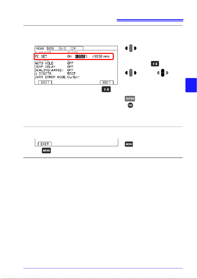
4.3 Correcting for the Effects of Temperature (Temperature Correction (TC))
Setting range
reference temperature : -10.0 to 99.9°C (default: 20°C)
temperature coefficient : -9999 to 9999ppm/°C (default: 3930ppm/°C)
Move the cursor to the setting you
wish to configure. Make the value
editable with the key.
2
Move the cursor to the digit you
wish to set with the left and right
cursor keys. Change the value
with the up and down cursor keys.
Change
values.
1
Move among
digits.
3
Accept
( Cancel)
Return to the
Measurement screen.
Set the reference temperature and temperature coefficient.
4
(Set the reference temperature and temperature coefficient by following steps 1
through 3 for each.)
Return to the Measurement screen.
5
53
4
Page 62

54
Range
Gain coefficient
(0.2000 to
1.9999)
×10
-3
(0.2000 to
1.9999)
×10
-2
(0.2000 to
1.9999)
×10
-1
(0.2000 to
1.9999)
×1
(0.2000 to
1.9999)
×10
(0.2000 to
1.9999)
×10
2
(0.2000 to
1.9999)
×10
3
30 m 00.000 000.00 0.0000 m 00.000 m 000.00 m 0.0000 00.000
300 m 000.00 0.0000 m 00.000 m 000.00 m 0.0000 00.000 000.00
3 0.0000 m 00.000 m 000.00 m 0.0000 00.000 000.00 0.0000 k
30 00.000 m 000.00 m 0.0000 00.000 000.00 0.0000 k 00.000 k
300 000.00 m 0.0000 00.000 000.00 0.0000 k 00.000 k 000.00 k
3 k 0.0000 00.000 000.00 0.0000 k 00.000 k 000.00 k 0.0000 M
30 k 00.000 000.00 0.0000 k 00.000 k 000.00 k 0.0000 M 00.000 M
300 k 000.00 0.0000 k 00.000 k 000.00 k 0.0000 M 00.000 M 000.00 M
3 M 0.0000 k 00.000 k 000.00 k 0.0000 M 00.000 M 000.00 M 0.0000 G
The Settings screen
appears.
Switch the function menu
to P.2/2.
1
2
4.4 Correcting Measured Values and Displaying Physical Properties Other than Resistance
4.4 Correcting Measured Values and Displaying Physical Properties Other than Resistance Values (Scaling Function)
This function applies a correction to measured values. It can be used to cancel the effects
of the probing position or differences between measuring instruments, or to apply a userspecified offset as an alternative to zero-adjustment. In addition, units can be specified,
allowing it to be used to convert measured values to physical properties other than resistance (for example, length).
Scaling is performed by means of the following equations:
RS = A × R + B
RS: Resistance value after scaling
R : Measured value after zero-adjustment and temperature correction
A : Gain coefficient Setting range: 0.2000 × 10
B : Offset Setting range: 0 to ±1 × 10⁹ (maximum resolution: 1 n)
Displayed and sent/received measured values as well as the printer output format vary with
the gain coefficient.
-3
to 1.9999 × 10
3
Open the Settings Screen.
1
Page 63

55
Move the cursor to the
[MEAS] tab with the left and
right cursor keys.
Enables the scaling function
Disables the scaling function (default) (go to step 8)
Selection
2
1
Setting range: 0.2000×10⁻³ to 1.9999×10
3
It is not possible to set the exponent (E+3, etc.) directly. Use
and to multiply by 10
and 1/10 as necessary.
Move the cursor to the setting you
wish to configure. Make the value
editable with the key.
2
Move the cursor to the digit you
wish to set with the left and right
cursor keys. Change the value
with the up and down cursor keys.
Change
values.
1
Move among
digits.
3
Accept
( Cancel)
Multiply by 10.
Multiply by 1/10.
Clear value.
4.4 Correcting Measured Values and Displaying Physical Properties Other than Resistance
Open the Measurement Settings Screen.
2
Enable the scaling function.
3
Set the gain coefficient.
4
4
Page 64

56
It is not possible to set the exponent (E+3, etc.) directly. Use
and to multiply by 10
and 1/10 as necessary.
Move the cursor to the setting you
wish to configure. Make the value
editable with the key.
2
Move the cursor to the digit you
wish to set with the left and right
cursor keys. Change the value
with the up and down cursor keys.
Change
values.
1
Move among
digits.
3
Accept
( Cancel)
Multiply by 10.
Multiply by 1/10.
Clear value.
Setting range: 0 to ±1×10⁹
(maximum resolution: 1 n, default: 0)
2
Use as the unit. (default)
(go to step 8)
Eliminate the unit.
(go to step 8)
Use a user-defined unit.
Selection
1
4.4 Correcting Measured Values and Displaying Physical Properties Other than Resistance
Set the offset.
5
Set the units for the displayed measured values.
6
Page 65
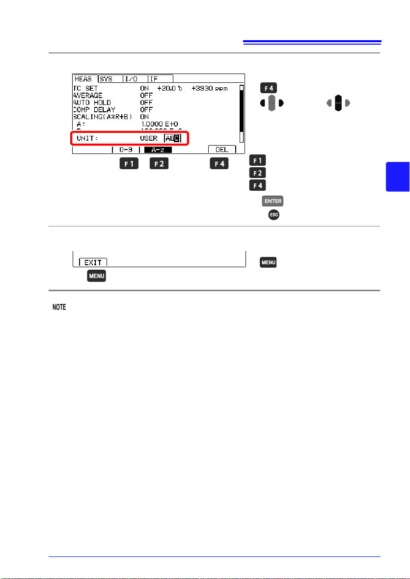
57
Enter a number from 0 to 9
Enter a letter from A to z
Delete 1 character.
1
Move the cursor to the digit you
wish to set with the left and right
cursor keys. Change the value
with the up and down cursor keys.
Change
values.
Move among
digits.
2
Accept
( Cancel)
Make the value editable with the
key.
Return to the
Measurement screen.
4.4 Correcting Measured Values and Displaying Physical Properties Other than Resistance
Edit the unit as desired.
7
Return to the Measurement screen.
8
4
Scaling calculation is performed on measured values after zero-adjustment calculation.
Consequently, measured values may not equal zero even after zero adjustment.
• If the calculation result exceeds the display range, the measured value will not be dis-
played at full scale.
Example: If you set an offset of 9 for the 3 range
Values in excess of 1 will be displayed as OvrRng.
• If the calculation result is negative, the displayed value will be negative.
Example: If you set an offset of -50 m for the 300 m range
If you measure 30 m, -20 m will be displayed.
Page 66

58
The Settings screen
appears.
Switch the function menu
to P.2/2.
1
2
Move the cursor to the
[MEAS] tab with the left and
right cursor keys.
2
5digits (35,000dgt.)
(default)
4digits (3,500dgt.)
Selection
1
Return to the
Measurement screen.
4.5 Changing the Number of Measured Value Digits
4.5 Changing the Number of Measured Value
Digits
Open the Settings Screen.
1
Open the Measurement Settings Screen.
2
Select the number of measurement digits.
3
Return to the Measurement screen.
4
Page 67

Judgment
Measured value > Upper limit value
Upper limit value Measured value Lower limit value
Measured value < Lower limit value
59
Function
This chapter explains measured value judgments (the comparator function). The comparator function provides the following capabilities:
• Displaying information on the instrument (COMP lamp Hi/IN/Lo)
• Sounding the beeper
(By default, the beeper is disabled.)
See: "Checking Judgments Using Sound (Judgment Sound Setting Function)"(p.68)
• Displaying data away from the instrument
The L2105 LED Comparator Attachment is an option.
See: "Checking Judgments with the L2105 LED Comparator Attachment (Option)"(p.70)
• Outputting judgment results to external equipment
See: "Chapter 8 External Control (EXT I/O)" (p. 89)
Moreover, the judgment timing can be delayed.
See: "Delaying the judge timing"(p.66)
Chapter 5
5
Page 68

60
Select the REF% (relative values) judgment mode
Decide whether a measured value is within specified tolerance
limits relative to a specified reference value (p. 64)
Select the ABS (absolute values) judgment mode
Decide whether a measured value is between specified upper
and lower threshold values (absolute values) (p. 62)
12.000 k... reference value
±0.08% ....... positive/negative
tolerance
example
100.00 m . upper threshold
80.00 m ... lower threshold
example
Hi
IN
IN
Lo
Hi
IN
Lo
Positive
tolerance [%]
Reference value []
Negative
tolerance [%]
Upper
threshold []
Lower
threshold []
5.1 Judging Measured Values (Comparator Function)
5.1 Judging Measured Values
(Comparator Function)
The comparator judgment mode can be set as one of the following:
Before Using the Comparator Function
• The comparator judgment indicator will function as follows for over-range events
(“OvrRng” display) and measurement faults (“- - - - -” display):
See: "Confirming Measurement Faults"(p.38)
Measured value display Comparator Judgment Indicator
+OvrRng Hi
-OvrRng Lo
- - - - -
• If power is turned off during comparator setting, changes to settings are lost as they
revert to their previous values. To accept the settings, press the .
Off (no judgment)
Page 69

5.1 Judging Measured Values (Comparator Function)
The Comparator Settings
screen appears.
Switch the comparator
function ON or OFF.
When the comparator function is OFF
Comparator judgments are indicated only when the comparator function is enabled.
When the comparator function is ON
Enabling and Disabling the Comparator Function
The comparator function is disabled by default.
When the function is disabled, comparator settings are ignored.
Open the Comparator Settings screen.
1
61
Enable or disable the comparator function.
2
Return to the Measurement screen.
3
The range cannot be changed while using the comparator function. To change the range,
do so with the and keys on the Comparator Settings screen. To use auto-ranging, turn OFF the comparator function.
5
Page 70
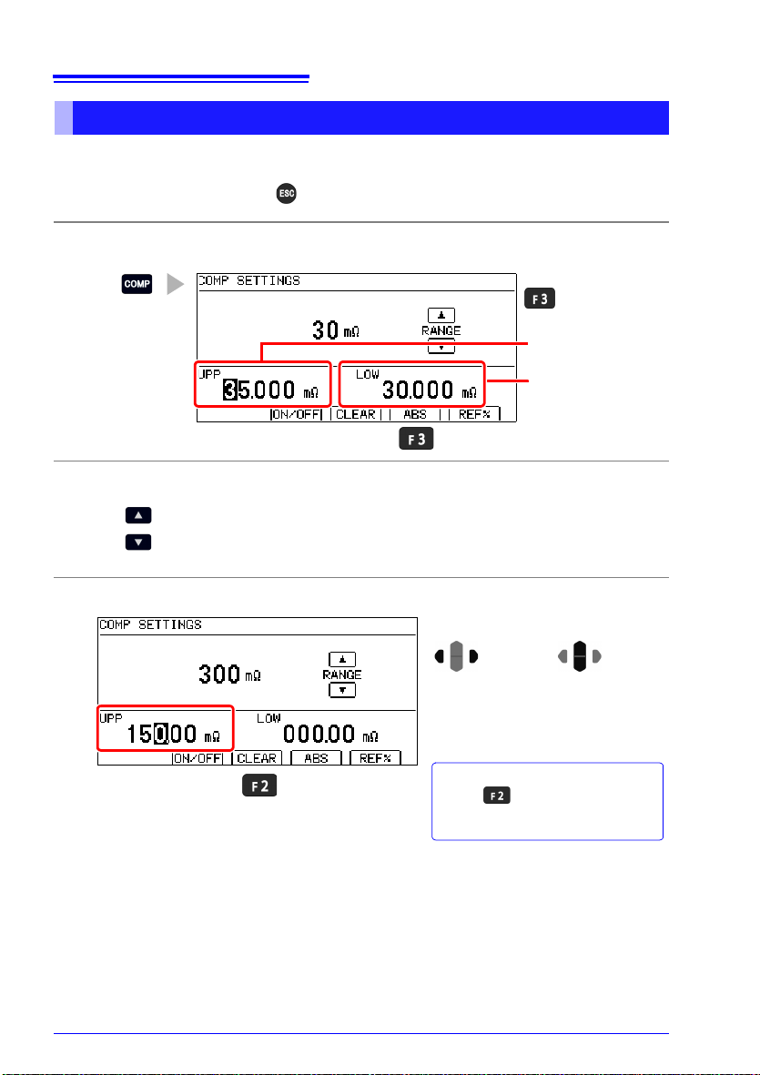
62
Upper threshold
Lower threshold
Switch to
ABS mode.
Select the range you wish to use.
Change the decimal point position and unit (changes each time you
press the button).
To Reset Numerical Values
Press to clear the upper limit
value. The upper limit value will be reset to 0.
Move the cursor to the digit you
wish to set with the left and right
cursor keys. Change the value
with the up and down cursor keys.
Change
values.
Move among
digits.
5.1 Judging Measured Values (Comparator Function)
Decide According to Upper/Lower Thresholds (ABS Mode)
Setting example: Upper threshold 150 m, lower threshold 50 m
To abort the setting process, press . Settings are abandoned and the display returns to the previous screen.
Open the absolute value threshold setting screen.
1
Set the range.
2
Set the positive tolerance.
3
Page 71
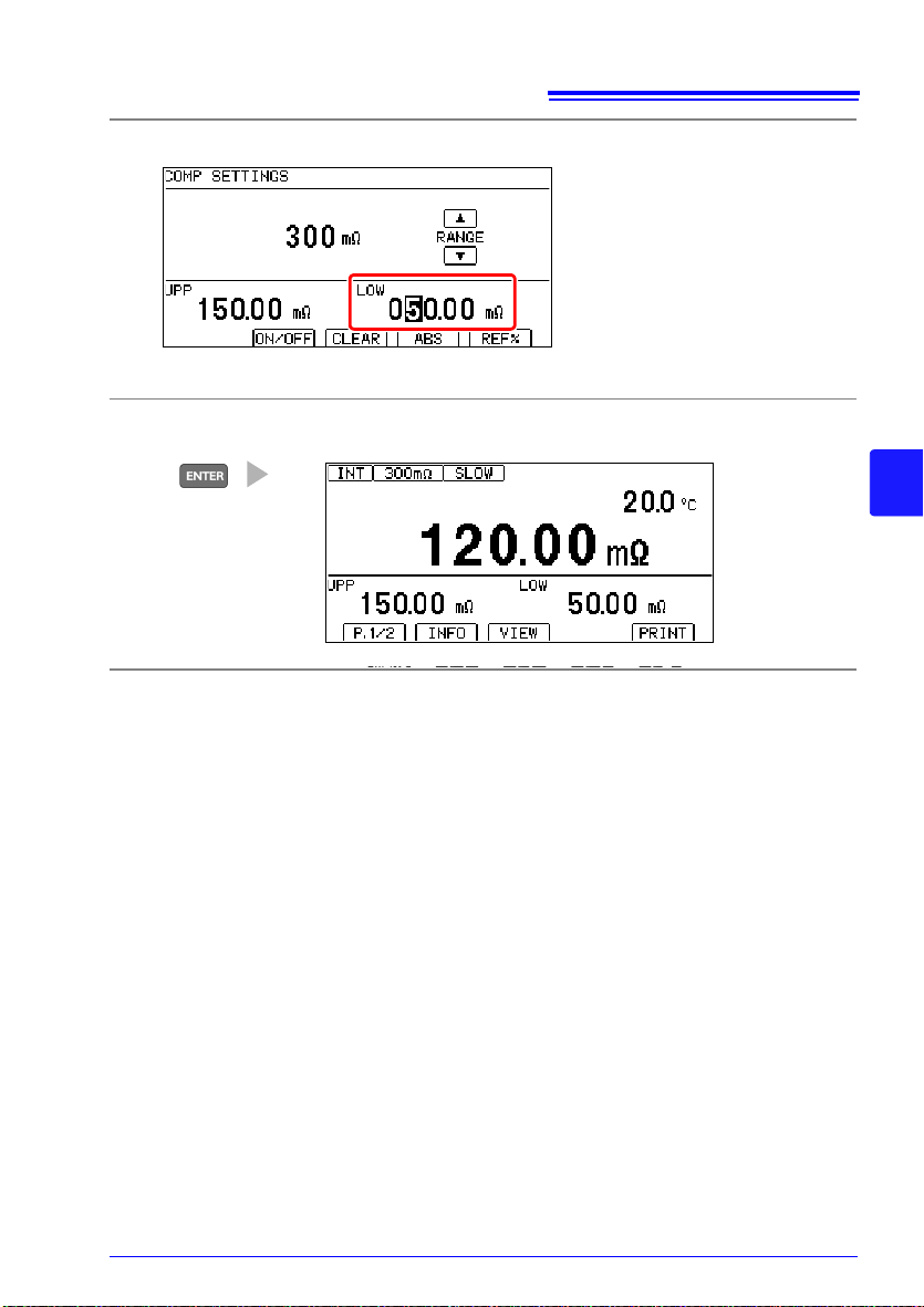
5.1 Judging Measured Values (Comparator Function)
Set the negative tolerance in the same way.
4
Accept the settings and return to the Measurement screen.
5
63
5
Page 72
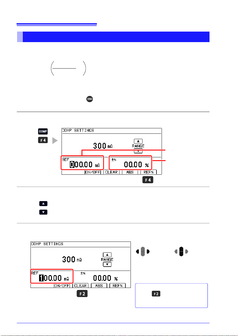
64
Relative Value =
(tolerance)
Reference
Value
Measured
Value
- 1
× 100 [%]
Display range: -999.99% to +999.99%
Reference value
Allowable range (upper and lower limit
ranges relative to the
reference value)
Select the range you wish to use.
Change the decimal point position and unit (changes each time you
press the button).
To Reset Numerical Values
Press to clear the reference
value. The reference value will be reset to 0.
Move the cursor to the digit you
wish to set with the left and right
cursor keys. Change the value
with the up and down cursor keys.
Change
values.
Move among
digits.
5.1 Judging Measured Values (Comparator Function)
Decide According to Reference Value and Tolerance (REF% Mode)
When REF% mode is enabled, the measured value will be displayed as an absolute value
(%).
Example setting: Set a reference value of 100 m with
To abort the setting process, press . Settings are abandoned and the display returns to the previous screen.
Open the relative tolerance setting screen.
1
Set the range.
2
Set the reference value.
3
Pressing an inoperative key during setting sounds a low-pitch beep (when the key beeper is enabled).
±1% allowable range.
Page 73

5.1 Judging Measured Values (Comparator Function)
To Reset Numerical Values
Press to clear the upper and
lower limit values. The upper and lower
limit values will be reset to 0.
Move the cursor to the digit you
wish to set with the left and right
cursor keys. Change the value
with the up and down cursor keys.
Change
values.
Move among
digits.
Set the allowable range (upper and lower limit values).
4
Accept the settings and return to the Measurement screen.
5
65
5
Page 74

66
Measurement
Fault (“- - - - -”)
is displayed
Measurement
order
Judge
1st 2nd 3rd 4th 5th 6th
1st
judgment
5th
judgment
6th
judgment
3rd
judgment
4th
judgment
2nd
judgment
Unjudged
Measurement
Fault (“- - - - -”)
is displayed
Judge
1st 2nd 3rd 4th 5th 6th
5th
judgment
6th
judgment
4th
judgment
Unjudged
Measurement
order
The Settings screen
appears.
Switch the function menu
to P.2/2.
1
2
Move the cursor to the
[MEAS] tab with the left and
right cursor keys.
5.1 Judging Measured Values (Comparator Function)
Delaying the judge timing
The judge timing can be delayed not to decide any judgment until a measurement value
becomes stable.
Example when the judge delay function is set to OFF
Example when the judge delay function is set to ON and the number of unjudged
measurements is three
Open the Settings Screen.
1
Open the Measurement Settings Screen.
2
Page 75

5.1 Judging Measured Values (Comparator Function)
Enables the judge delay
function
Disables the judge delay
function (default) (go to
step 5)
Selection
2
1
Move the cursor to the setting you
wish to configure. Make the value
editable with the key.
2
Move the cursor to the digit you
wish to set with the left and right
cursor keys. Change the value
with the up and down cursor keys.
Change
values.
1
Move among
digits.
Setting range: 1 to 100 times (default: 1 times)
3
Accept
( Cancel)
Return to the
Measurement screen.
Enable the judge delay function.
3
Set the the number of unjudged measurements.
4
67
5
Return to the Measurement screen.
5
• When the auto-hold function is set to ON, the judge delay function is automatically set to
OFF.
• For Non-Free-Run, the judge delay function is automatically set to OFF.
Page 76

68
The Settings screen
appears.
Switch the function menu
to P.2/2.
1
2
Move the cursor to the [SYS]
tab with the left and right cursor keys.
2
to
Select the sound you
desire.
Disable the beeper.
(default) (go to step 5)
Selection
1
5.1 Judging Measured Values (Comparator Function)
Checking Judgments Using Sound (Judgment Sound Setting Function)
The comparator judgment beeper can be enabled and disabled.
The judgment beeper is disabled (OFF) by default.
Separate judgment tones can be set for Hi, IN, and Lo judgments.
Open the Settings Screen.
1
Open the System Setting Screen.
2
Select the sound you desire for Hi judgments.
3
Page 77
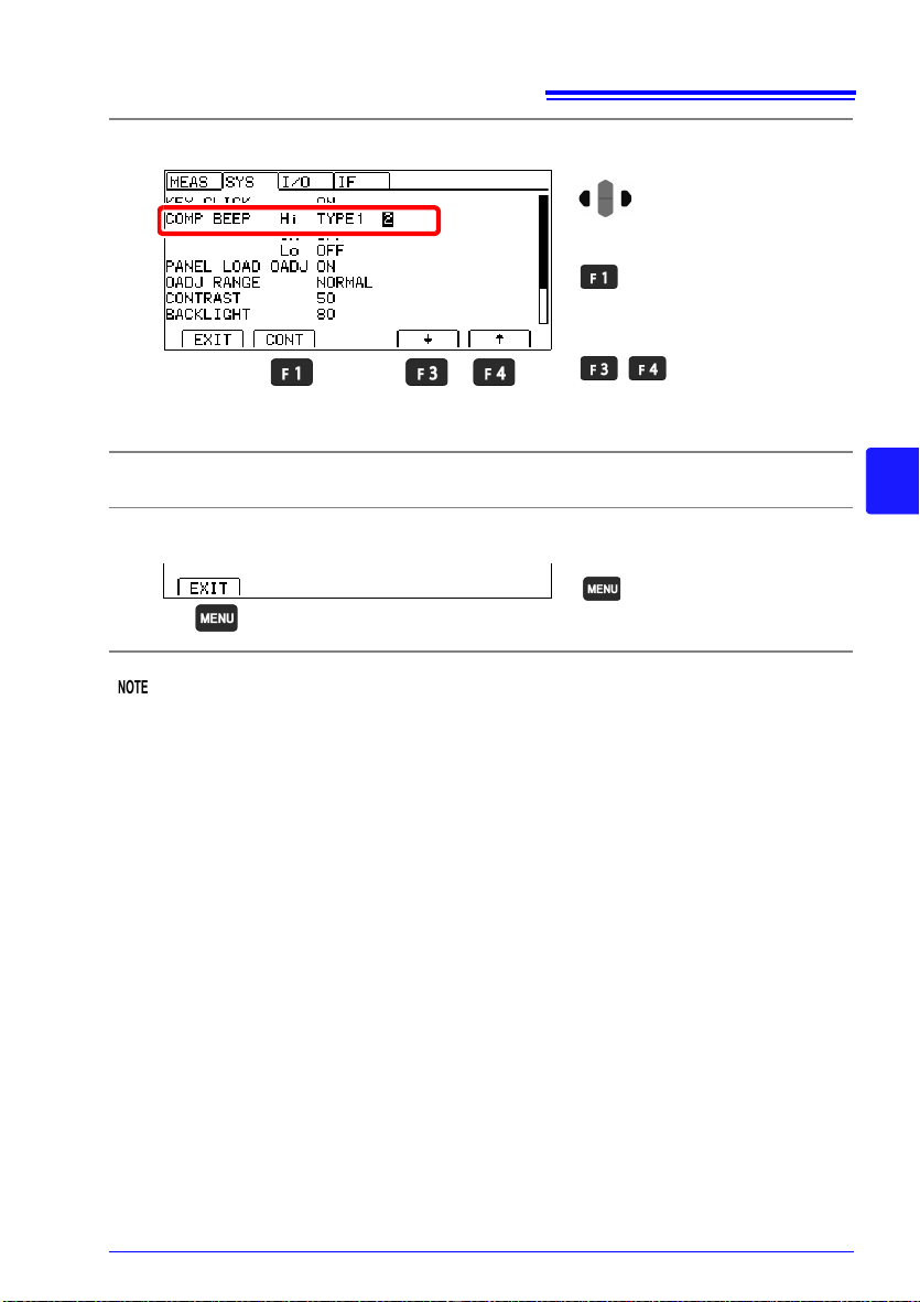
5.1 Judging Measured Values (Comparator Function)
Move the cursor to the setting
you wish to configure.
To sound the beeper con-
tinuously
To set the number of beeps:
Change the number
of beeps.
Setting range: 1 to 5 times, continuous
Return to the
Measurement screen.
Select the number of times to sound the beeper for Hi judgments.
4
Repeat this process to configure settings for IN and Lo judgments.
5
Return to the Measurement screen.
6
69
5
The volume cannot be adjusted.
If the volume is too loud, cover the opening on the bottom of the instrument, for example
with a piece of tape.
Page 78
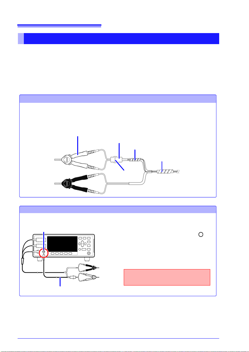
70
Attaching the LED Comparator Attachment
Position the LED Comparator Attachment where you wish.
Example: Using a tie band and two of the spiral wrappers that came with the L2105, attach the
LED Comparator Attachment to a measurement lead.
L2105 LED Comparator Attachment
L2101 Clip Type Lead
Spiral wrapper (small)
Spiral wrapper (large)
Tie band
Connecting the LED Comparator Attachment to the Instrument
Front Panel
L2105 LED Comparator Attachment
COMP.OUT jack
1 Confirm that the instrument's Main
power switch (rear panel) is OFF( ).
2 Plug the L2105 LED Comparator Attach-
ment into the COMP.OUT jack
on the
front panel.
Insert the plug securely all the way
into the jack.
2
5.1 Judging Measured Values (Comparator Function)
Checking Judgments with the L2105 LED Comparator Attachment (Option)
By connecting the L2105 LED Comparator Attachment to the COMP.OUT jack, you can
check judgment results easily at a distance from the instrument. The indicator will turn
green for IN judgments and red for Hi and Lo judgments.
Connection Methods
Before connecting the LED Comparator Attachment, read "Operating Precautions"(p.5)
carefully.
Page 79

71
Saving and Loading Panels
(Saving and Loading
Measurement Conditions)
Current measurement conditions can be saved and loaded using the panel load function
from the key operations, communications commands, or EXT-I/O.
The instrument can save up to 10 sets of measurement conditions. Saved conditions are
retained even when the instrument is turned off.
Settings that can be saved with the Panel Save function
• Panel name
• Resistance measurement range
• Measurement speed
• Averaging
• Comparator
• Comparator judgment beeper
• Scaling
• Temperature correction (TC)
• Auto-hold
• Zero-Adjust (Loading of these values can be disabled.)
Chapter 6
6
Page 80

72
The Panel List Screen
appears.
Save the conditions.
Selection
1
2
Enter a number from 0 to 9
Enter a letter from A to Z, or
an underbar character ( _ ).
Delete 1 character.
1
Move the cursor to the character
you wish to set with the left and
right cursor keys. Change the
character with the up and down
cursor keys.
Change
characters.
Move
among
characters.
2
Accept
( Cancel)
6.1 Saving Measurement Conditions (Panel Save Function)
6.1 Saving Measurement Conditions
(Panel Save Function)
Open the Panel List Screen.
1
Save the measurement conditions.
2
Enter the panel name.
3
(If you enter the number of a previously saved panel, a warning message will
be displayed.)
Page 81

73
The Panel List Screen
appears.
2
Selection
1
Load the panel.
(You can also load the
panel with the
key.)
Data saved for selected panel
Load the panel and switch
to the Measurement screen
(you can also do this with
the key).
Cancel the operation and
return to the previous
screen. (you can also do
this with the key)
The name of the loaded
panel will be displayed on
the Measurement screen.
6.2 Loading Measurement Conditions (Panel Load Function)
6.2 Loading Measurement Conditions
(Panel Load Function)
Loads the measurement settings saved by the Panel Save function.
By default, loading a panel causes zero-adjustment values to be loaded. If you do not wish
to load zero-adjustment values, see "Preventing Loading of Zero-adjustment Values"(p.74).
Open the Panel List Screen.
1
Select a panel number.
2
6
Verify that the confirmation message is shown and return to the Measurement
3
screen.
Page 82

74
The Settings screen
appears.
Switch the function menu
to P.2/2.
1
2
Move the cursor to the [SYS]
tab with the left and right cursor keys.
2
When a panel is loaded,
change zero-adjustment
values to the values in
effect when the panel was
saved. (default)
Do not change zero-adjustment values, even when
panel data is loaded.
Selection
1
Return to the
Measurement screen.
6.2 Loading Measurement Conditions (Panel Load Function)
• Panels can also be loaded with the EXT I/O LOAD0 to LOAD3 control and communica-
tions commands.
See: "Chapter 8 External Control (EXT I/O)"; "Input Signals" (p. 93)
For more information about commands, see the included application disc.
• If measurement conditions are changed after being loaded, the panel name will no longer
be displayed.
Preventing Loading of Zero-adjustment Values
By default, zero-adjustment values are also loaded along with panel data. The following
procedure can be used to prevent loading of zero-adjustment values.
Open the Settings Screen.
1
Open the System Setting Screen.
2
Select whether to load zero-adjustment values.
3
Return to the Measurement screen.
4
Page 83

6.3 Changing Panel Names
The Panel List Screen
appears.
2
Selection
1
Edit the panel name.
Enter a number from 0 to 9
Enter a letter from A to Z, or
an underbar character ( _ ).
Delete 1 character.
1
Move the cursor to the character
you wish to set with the left and
right cursor keys. Change the
character with the up and down
cursor keys.
Change
characters.
Move
among
characters.
2
Accept
( Cancel)
Return to the
Measurement screen.
Open the Panel List Screen.
1
Select a panel number.
2
75
6.3 Changing Panel Names
6
Edit the panel name.
3
Return to the Measurement screen.
4
Page 84

76
The Panel List Screen
appears.
2
Selection
1
Delete the panel.
Delete the panel and switch
to the previous screen (you
can also do this with the
key).
Cancel the operation and
return to the previous
screen. (you can also do
this with the key)
Return to the
Measurement screen.
6.4 Deleting Panel Data
6.4 Deleting Panel Data
Open the Panel List Screen.
1
Select a panel number.
2
Verify that the confirmation message is shown and return to the Measurement
3
screen.
Return to the Measurement screen.
4
Once a panel’s data is deleted, it cannot be restored (the delete operation cannot be
undone).
Page 85

System Settings Chapter 7
This chapter describes system settings.
"7.1 Disabling and Enabling Key Operations" (p. 78)
"7.2 Power Line Frequency Manual Setting" (p. 80)
"7.3 Enabling or Disabling the Key Beeper" (p. 82)
"7.4 Adjusting Screen Contrast" (p. 83)
"7.5 Adjusting the Backlight" (p. 84)
"7.6 Initializing (Reset)" (p. 85)
77
7
Page 86

78
Key operations other than AUTO, RANGE , SPEED, COMP,
PANEL, 0ADJ, PRINT, ENTER (trigger) and MENU [UNLOCK] (key-lock
cancel) keys are disabled.
To disable key operations: select [MENU]
[M.LOCK] is displayed when returning to the measurement screen.
Disabling All Except Comparator Settings
Only basic settings
(range, speed, comparator, panel load)
are enabled.
All key operations except ENTER (trigger) and MENU [UNLOCK] (keylock cancel) are disabled.
To disable key operations: select [FULL]
[F.LOCK] is displayed when returning to the measurement screen.
Disabling All Key Operations Including Comparator
Settings
Key operations to
change settings are
disabled (although
key-lock can be canceled).
Asserting (ON) the EXT I/O KEY_LOCK signal disables all panel keys, including MENU [UNLOCK] (key-lock cancel) and MENU [LOCAL] (disables remote control). However, the ENTER (trigger) key remains
enabled (p. 89).
To cancel the key lock state: Turn OFF the EXT I/O KEY_LOCK signal.
When you execute panel load operation by sending a LOAD signal, no
key operation is available while the LOAD signal is being the on state.
To enable key operation, switch the LOAD signal to the off state after the
panel load is complete.
Disabling All Panel Keys
All key operations are
disabled.
Display the Key Lock
Selection screen.
Switch the function menu
to P.2/2.
1
2
7.1 Disabling and Enabling Key Operations
7.1 Disabling and Enabling Key Operations
Disabling Key Operations (Key-Lock Function)
Activate the key-lock function to disable the instrument’s front panel key operations.
Three key-lock levels are available to suit specific purposes.
1
Page 87

7.1 Disabling and Enabling Key Operations
Disable all except key-lock
cancel and return to the
Measurement screen.
Disable all except key-lock
cancel and basic settings
change and return to the
Measurement screen.
Return to the
Measurement screen.
Enable or disable key operations.
2
[UNLOCK] is displayed.
(Key-lock operation triggered by the EXT I/O KEY_LOCK signal is not displayed.)
Re-Enabling Key Operations (Key-Lock Cancel)
Key-lock can be canceled only when [UNLOCK] is displayed.
Press and hold [UNLOCK] for one second.
79
7
If key operations are disabled by the KEY_LOCK signal, de-assert (OFF) the signal to
unlock the keys.
When you execute panel load operation by sending a LOAD signal, no key operation is
available while the LOAD signal is being the on state.
To enable key operation, switch the LOAD signal to the off state after the panel load is complete.
Page 88

80
The Settings screen
appears.
Switch the function menu
to P.2/2.
1
2
Move the cursor to the [SYS]
tab with the left and right cursor keys.
7.2 Power Line Frequency Manual Setting
7.2 Power Line Frequency Manual Setting
With the default setting (AUTO), the instrument attempts to automatically detect the line frequency, but manual setting is also available.
• Unless the line frequency is set correctly, measured values may be unstable.
An error message appears if line noise is high enough to prevent correct frequency
detection (ERR:097 (p.169)). In that case, set the instrument’s line frequency manually.
• When the AUTO setting is selected, the line frequency is automatically set to 50 or 60 Hz
when the instrument is turned on or reset.
However, automatic detection is not available when the line frequency changes after turning power on or resetting.
If the actual line frequency deviates from 50 or 60 Hz, select the closest frequency.
Examples:
If the actual line frequency is 50.8 Hz, select the 50 Hz setting.
If the actual line frequency is 59.3 Hz, select the 60 Hz setting.
Open the Settings Screen.
1
Open the System Setting Screen.
2
Page 89

Select the line frequency being used.
2
Automatically detect local
line frequency (default)
When the line frequency is
50 Hz
When the line frequency is
60 Hz
Selection
1
Return to the
Measurement screen.
3
Return to the Measurement screen.
4
81
7.2 Power Line Frequency Manual Setting
7
Page 90

82
The Settings screen
appears.
Switch the function menu
to P.2/2.
1
2
Move the cursor to the [SYS]
tab with the left and right cursor keys.
2
Enables the beeper
(default)
Disables the beeper
Selection
1
Return to the
Measurement screen.
7.3 Enabling or Disabling the Key Beeper
7.3 Enabling or Disabling the Key Beeper
The key beeper sound can be enabled and disabled.
The key beeper is enabled (ON) by default.
Open the Settings Screen.
1
Open the System Setting Screen.
2
Select whether to enable or disable the key beeper.
3
Return to the Measurement screen.
4
(Version 2.00 and later only)
To disable the key beeper, error beep, and auto-hold beep, turn off the instrument and then
turn it back on while holding down the [F1] and [ENTER] keys. "(
displayed as the KEY CLICK setting, and the error beep and auto-hold beep will be set to
the same setting as the keep deeper.
ERR,AUTO HOLD)" will be
Page 91

83
The Settings screen
appears.
Switch the function menu
to P.2/2.
1
2
Move the cursor to the [SYS]
tab with the left and right cursor keys.
2
Decrease the contrast.
Increase the contrast.
Selection
1
Setting range: 0 to 100%, 5% step
(default: 50%)
Return to the
Measurement screen.
7.4 Adjusting Screen Contrast
7.4 Adjusting Screen Contrast
The screen may become hard to see when ambient temperature changes. In this case,
adjust the contrast.
Open the Settings Screen.
1
Open the System Setting Screen.
2
7
Adjust the contrast.
3
Return to the Measurement screen.
4
Page 92
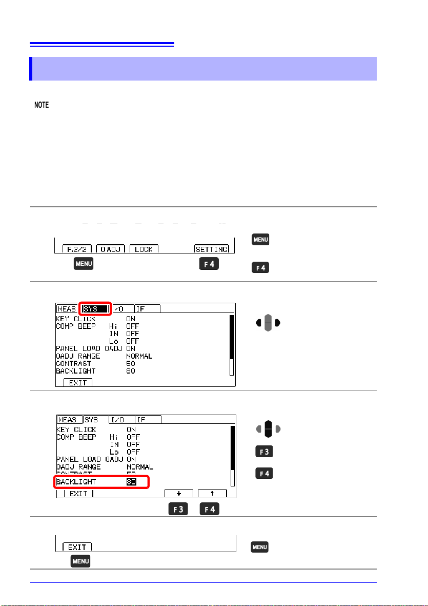
84
The Settings screen
appears.
Switch the function menu
to P.2/2.
1
2
Move the cursor to the [SYS]
tab with the left and right cursor keys.
Selection
1
2
Decrease the backlight
brightness.
Increase the backlight
brightness.
Setting range: 0 to 100%, 5% step
(default: 80%)
Return to the
Measurement screen.
7.5 Adjusting the Backlight
7.5 Adjusting the Backlight
Adjust backlight brightness to suit ambient illumination.
• When external (EXT) triggering is selected, backlight brightness is automatically reduced
after non-operation for one minute.
(Version 2.00 and later only)
To disable automatic dimming of the backlight, turn off the instrument and then turn it
back on while holding down the [F1] and [ENTER] keys. The backlight will no longer be
dimmed. If the key beeper is turned off while using this setting, the error beep and autohold beep will also be disabled.
See: (p.82)
• Be aware that the display may be hard to see when brightness is set too low (near 0%).
Open the Settings Screen.
1
Open the System Setting Screen.
2
Adjust the backlight.
3
Return to the Measurement screen.
4
Page 93
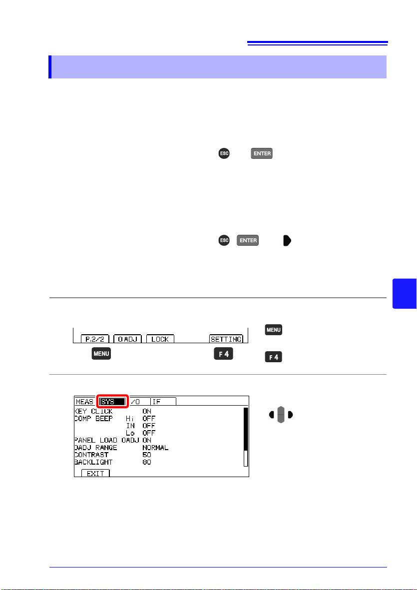
85
The Settings screen
appears.
Switch the function menu
to P.2/2.
1
2
Move the cursor to the [SYS]
tab with the left and right cursor keys.
7.6 Initializing (Reset)
7.6 Initializing (Reset)
Two reset functions are available.
For more information about communications commands, see the included application disc.
Reset: Returns measurement conditions (except the panel data) to factory defaults.
The instrument can be reset by three methods.
• Reset from the System setting screen
• Turn on the instrument while holding down and .
• Reset by remote control command
∗RST command (Interface settings are not initialized.)
System reset: Returns all measurement conditions and the panel save data to factory
The instrument can be system reset by three methods.
• System reset from the System setting screen
• Turn on the instrument while holding down , , and .
• Reset by remote control command
:SYSTem:RESet command (Interface settings are not initialized.)
This procedure describes reset from the System setting screen.
Open the Settings Screen.
1
Open the System Setting Screen.
2
defaults.
7
Page 94

86
Selection
1
2
Perform a reset.
Perform a system reset.
Cancel the operation
Execute
7.6 Initializing (Reset)
Select RESET.
3
Select whether to initialize the instrument.
4
The Measurement screen is displayed when system reset finishes.
Page 95

7.6 Initializing (Reset)
Default Settings
Screen Setting and Key Default Settings See
Measurement screen COMP OFF (p.61)
Measurement screen
(P.1/2)
Measurement screen
(P.2/2)
Setting
screen
(SETTING)
Measurement
Settings screen
(MEAS)
System
Settings screen
(SYS)
EXT I/O
Settings screen
*1
(I/O)
Communications
Interface
Settings screen
*1
(IF)
AUTO ON
(RANGE) 3M
SPEED SLOW (p.33)
VIEW (F2) OFF (p.35)
0 ADJ (F1) OFF
LOCK (F2) OFF
TC SET OFF (p.52)
AVERAGE OFF (p.50)
AUTO HOLD OFF (p.41)
COMP DELAY OFF (p.66)
SCALING(A∗R+B) OFF
A: +1.0000E+0
B: +0.0000E+0
UNIT:
DIGITS 5DGT (p.58)
CURR ERROR MODE CurErr (p.40)
KEY CLICK ON (p.82)
COMP BEEP Hi OFF
Lo OFF
PANEL LOAD 0ADJ ON (p.74)
0ADJ RANGE NORMAL (p.47)
CONTRAST 50 (p.83)
BACKLIGHT 80 (p.84)
POWER FREQ AUTO (p.80)
TRIG SOURCE INT (p.109)
TRIG EDGE OFF ON (ON EDGE) (p.111)
TRIG/PRINT FILT OFF (p.113)
EOM MODE HOLD (p.115)
JUDGE/BCD MODE JUDGE (p.117)
INTERFACE RS232C (p.123)
SPEED 9600bps (p.126)
DATA OUT OFF (p.133)
CMD MONITOR OFF (p.131)
PRINT INTRVL OFF (p.142)
PRINT COLUMN 1LINE (p.141)
(p.32)
(p.44)
(p.78)
(p.54)
(p.68)IN OFF
*1 RM3544-01 only
87
7
Page 96

88
7.6 Initializing (Reset)
Page 97

External Control
Signal input/output
89
(EXT I/O)
The EXT I/O connector on the rear of the instrument supports external control by providing
output of the EOM and comparator judgment signals, and accepting input of TRIG and
KEY_LOCK signals. All signals are isolated from the measurement circuit and ground (I/O
common pins are shared). Input circuit can be switched to accommodate either current sink
output (NPN) or current source output (PNP).
Confirm input and output ratings, understand the safety precautions for connecting a control
system, and use accordingly.
Check the controller’s I/O specifications.
Set the instrument’s NPN/PNP switch. (p.90)
Chapter 8
8
Connect the instrument’s EXT I/O connector to the controller. (p.91)
Make instrument settings. (p. 109)
Page 98

90
Left: Current sink (NPN)
Right: Current source (PNP)
8.1 External Input/Output Connector and Signals
8.1 External Input/Output Connector
and Signals
Switching between Current Sink (NPN) and Current Source (PNP)
Before switching, see "Before Switching between Current Sink (NPN) and Current Source
(PNP)" (p. 11).
The NPN/PNP switch allows you to change the type of programmable controller that is supported.
The instrument ships with the switch set to the NPN position.
See: "8.3 Internal Circuitry"(p.104)
NPN/PNP switch setting
NPN PNP
RM3544 input circuit Supports sink output. Supports source output.
RM3544 output circuit Non-polar Non-polar
ISO_5V output +5 V output -5 V output
Page 99

91
EXT I/O Connector (Instrument Side)
Connector: (Instrument Side)
37-pin D-sub female with #4-40 screws
Mating Connectors:
DC-37P-ULR (solder type) /
DCSP-JB37PR (pressure weld type)
Japan Aviation Electronics Industry Ltd.
12345678910111213141516171819
202122232425262728293031323334353637
TRIG, IN0
BCD_LOW
KEY_LOCK
LOAD1
LOAD3
(Reserved)
(Reserved)
ISO_5V
ISO_COM
ERR
HI, HILO
LO, BCD2-1, RNG_OUT1
BCD2-3, RNG_OUT3
BCD3-1
BCD3-3
BCD4-1
BCD4-3
OUT0, BCD5-1, BCD1-1
OUT2, BCD5-3, BCD1-3
0ADJ
(Reserved)
LOAD0
LOAD2
(Reserved)
(Reserved)
PRINT, IN1
ISO_COM
EOM
INDEX, BCD2-0, RNG_OUT0
IN
BCD2-2, RNG_OUT2
BCD3-0
BCD3-2
BCD4-0
BCD4-2
BCD5-0, BCD1-0
OUT1, BCD5-2, BCD1-2
8.1 External Input/Output Connector and Signals
Connector Type and Signal Pinouts
Before connecting a connector, see "Before Connecting EXT I/O" (p. 11). Use of EXT I/O
enables the following control functionality:
• Measurement start (TRIG) Measurement end (EOM, INDEX)
Acquisition of judgment results (HI, IN, LO, ERR)
• Measurement start (TRIG) Measurement end (EOM, INDEX)
Acquisition of measured values (BCD_LOW, BCDm_n, RNG_OUTn)
• Panel load (LOAD0 to LOAD3, TRIG)
• General-purpose I/O (IN0, IN1, OUT0, OUT1, OUT2)
The functionality described in "Performing an I/O Test (EXT I/O Test Function)" (p. 118)
provides a convenient way to check external I/O operation.
TRIG
1
IN0
IN
2 BCD_LOW IN
3 KEY_LOCK IN Key-Lock Level 22 LOAD0 IN Panel load Level
4 LOAD1 IN Panel load Level 23 LOAD2 IN Panel load Level
Pin Signal name I/O Function Logic Pin Signal name I/O Function Logic
External trigger
General-pur-
pose input
Edge 20 0ADJ IN Zero adjust Edge
BCD
Lower byte
Level 21 (Reserved) - - -
output
8
Page 100

92
8.1 External Input/Output Connector and Signals
Pin Signal name I/O Function Logic Pin Signal name I/O Function Logic
5 LOAD3 IN Panel load Level 24 (Reserved) - - -
6 (Reserved) - - - 25 (Reserved) - - -
7(Reserved) - - - 26
Isolated power
8ISO_5V
9ISO_COM -
10 ERR OUT
11 HI, HILO OUT
12
13
14 BCD3-1 OUT BCD Level 33 BCD3-2 OUT BCD Level
15 BCD3-3 OUT BCD Level 34 BCD4-0 OUT BCD Level
16 BCD4-1 OUT BCD Level 35 BCD4-2 OUT BCD Level
17 BCD4-3 OUT BCD Level 36
18
19
LO,
BCD2-1,
RNG_OUT1
BCD2-3,
RNG_OUT3
OUT0,
BCD5-1,
BCD1-1
OUT2,
BCD5-3,
BCD1-3
appli-
supply +5 V
cable
(-5 V) output
Isolated
common signal
ground
Measurement
fault
Comparator
judgment
Comparator
OUT
OUT BCD Level 32 BCD3-0 OUT BCD Level
OUT
OUT
judgment
BCD
General-pur-
pose output
BCD
General-pur-
pose output
BCD
-27ISO_COM -
-28 EOM OUT
Level 29
Level 30 IN OUT
Level 31
Level 37
Level
PRINT
IN1
INDEX,
BCD2-0,
RNG_OUT0
BCD2-2,
RNG_OUT2
BCD5-0,
BCD1-0
OUT1,
BCD5-2,
BCD1-2
OUT
OUT BCD Level
OUT BCD Level
OUT
Printing of
measured values
IN
General-pur-
pose input
Isolated
common signal
ground
End of
measurement
Analog
measurement
finished
Comparator
judgment
General-pur-
pose output
Edge
-
Level
Level
Level
Level
BCD
• The 0ADJ signal should be asserted (ON) for at least 10 ms.
• The connector's frame is connected to the instrument's rear panel (metal portions) as well
as the power inlet's protective ground terminal.
When switching panel load operation using commands or key operation, fix pins 4 and 5
as well as 22 and 23 to ON or OFF.
 Loading...