

Hioki RM3544, RM3544-01 Instruction Manual

Instruction Manual
RM3544
RM3544-01
RESISTANCE METER
June 2014 Revised edition 2 RM3544A981-02 14-06H

Using This Instruction Manual
To do this… Refer to these sections in t his m anual.
Review important
information
Start using the instrument right away
Learn more about
instrument functions
Learn more about
product specifications
Troubleshoot a problem
Learn more about
resist ance measure ment
Learn more about
communicat i o ns commands
Safety Informati o n (p.3)
Operating Precautions (p.5)
Overview (p.15)
Search for the function in question in the table
of contents (p.i) or the index (p.Index 1).
Specifications (p. 145)
Troubleshooting (p. 160)
Appendix (p . A1)
Communications Command Instruction Manual
(on the application di sc)


Contents
Introduction.....................................................1
Verifying Package Contents...........................1
Safety Information..........................................3
Operating Precautions......... ..... ...... ..... ...........5
Chapter 1 Overview 15
1.1 Product Overview and Features ........15
1.2 Names and Functions of Parts ...........17
1.3 Measurement Process .......................19
1.4 Screen Organization and
Operation Overview ...........................21
Contents
Chapter 4 Cu sto m iz ing Mea-
surement Conditions
43
4.1 Zero Adjustment .................................44
4.2 Stabilizing Measured Values
(Averaging Function) ..........................50
4.3 Correcting for the Effect s of Temper atur e
(Temperatu re Correction (TC)) ...........52
4.4 Correcting Meas ured Value s and D isplaying Physical Properties Other than Resis-
tance Values (Scaling Function) .........54
4.5 Changing the Number of Measured
Value Digits ........................................58
i
1
2
3
4
5
Chapter 2 Measurement
Preparations 25
2.1 Connecting the Power Cord............... 25
2.2 Connecting Measurement Leads .......26
2.3 Connecting Z2001 Temperature Sensor
(When using the TC) ..........................27
2.4 Turning the Power On and Off ...........28
Turning On the Instrument with the
Main Power Switch ...................................28
Turning Off the Instrument with the
Main Power Switch ...................................28
Canceling the Standby State ....................28
Placing the Instrument in the
Standby State ........................................ ...29
2.5 Pre-Operation Inspection ...................30
Chapter 3 Basic Measurements
31
3.1 Selecting the Measurement Range ....32
3.2 Setting the Measurement Speed .......33
3.3 Connecting Measurement Leads to the
Measurement Target ..........................34
3.4 Checking Measured Values ...............35
Switching the Display ................................35
Conf irm ing Me asu rem en t Faul ts ............... 3 8
Holding Measured Values .........................41
6
Chapter 5 J ud gm en t
Function 59
5.1 Judging Measured Values
(Comparator Function) .......................60
Enabling and Disabling the Comparator
Function ............... .................................... 61
Decide According to Upper/Lower Thresholds
(ABS Mode) ............................ ..... ..... ..... .. 62
Decide According to Reference Value and
Tolerance (REF% Mode) ......................... 64
Delaying the judge timing ......................... 66
Checking Judgments Using Sound
(Judgment Sound Setting Function) ........ 68
Checking Judgments with the L2105 LED
Comparator Attachment (Option) ............. 70
Chapter 6 Saving and Loading
Panels (Saving and
Loading Measurement Conditions) 71
6.1 Saving Measurement Conditions
(Panel Save Function) ........................72
6.2 Loading Measurement Conditions
(Panel Load Function) ........................73
Preventing Loading of Zero-adjustment
Values .................. .................................... 74

ii
Contents
6.3 Changing Panel Names .....................75
6.4 Deleting Panel Data ...........................76
Chapter 7 System Settings 77
7.1 Disabling and Enabling Key Operations
...........................................................78
Disabling Key Operations
(Key-Lock Function) ................................. 78
Re-Enabling Key Operations
(Key-Lock Cancel) ................................... 79
7.2 Power Line Frequency Manual Setting
...........................................................80
7.3 Enabling or Disabling the Key Beep er 82
7.4 Adjusting Screen Contrast ..................83
7.5 Adjusting the Backlight .......................84
7.6 Initializing (Reset) ...............................85
Default Settings ........................................ 87
Chapter 8 External Control
(EXT I/O) 89
8.1 External Input/Ou tput Connector
and Signals......................................... 90
Switching between Current Sink (NPN) and
Current Source (PNP) .............................. 90
Connector Type and Signal Pinouts ........ 91
Signal Descriptions .................................. 93
8.2 Timing Chart .......................................97
From Start of Measurement to Acquisition
of Judgment Results ................................ 97
Zero-adjustment timing ............................ 99
Panel Load Timing ................................. 100
BCD Signal Timing ................................. 100
Output Signal State at Power-On ........... 101
Acquisition Process When Using an
External Trigger ..................................... 102
8.3 Internal Circuitry ...............................104
Electrical Specifications ......................... 106
Connection Examples ............................ 107
8.4 External I/O Settings ........................108
Setting Measurement Start Conditions
(Trigger Source) ..................................... 108
Setting the TRIG Signal Logic ................ 110
Eliminating TRIG/PRINT Signal Chatter
(Filter Function) ...................................... 112
Setting EOM Signal ................................ 114
Switching Output Modes
(JUDGE Mode/ BCD Mode) ................... 116
8.5 Checking External Control ...............117
Performing an I/O Test
(EXT I/O Test Function) ......................... 117
8.6 Supplied Connector Assembly .........119
Chapter 9 Communications
(USB/ RS-232C
Interface) 121
9.1 Overview and Features ....................121
Specifications ............. ............................ 122
9.2 Preparations before Use
(Connections and Settings) .............123
Using the USB Interface .........................123
Using the RS-232C Interface ................. 126
9.3 Controlling the Instrument with
Commands and Acquiring Data ....... 130
Remote and Local States ....................... 130
Displaying Communications Commands
(Communications Monito r Function ) ...... 131
9.4 Auto-Exporting Measu red Va lues (at En d
of Measurement) (Data Output Function)
..........................................................133
Chapter 10Printing (Using an
RS-232C Printer) 137
10.1 Connecting the Printer to the Instrument
..........................................................137
10.2 Printing .............................................140
Printing Measured Values and Comparator
Judgments .................. ......... .......... .... ..... 140
Printing List of Measuremen t Cond it ions
and Settings ........................................... 140
Chapter 11Specifications 145
11.1 Instrument Specifications ........ ...... ...145
Measurement Ranges ................... .........145
Measurement Method ............................ 145
Measurement Specifications ..................1 46
About Instrument Accuracy .................... 148
Functions ............... ..... .... ..... ..... ..... .... ..... 149
Interface ................ ................................. 154

Environment and Safety Specifications ..158
Accessories ............................................158
Options ...................................................158
Chapter 12Maintenance and
Service 159
12.1 Troubleshooting ...............................160
Q&A (Frequently Asked Questions) ........160
Error Displays and Remedies .................169
12.2 Replacing the Measurement Circuit’s
Protective Fuse ................................171
12.3 Inspection and Repair ......................172
Appendix A 1
Appendix 1Block Diagram ..........................A 1
Appendix 2Four-Terminal (Voltage-Drop)
Method......................................A 2
Appendix 3 DC and AC Measurement.........A 3
Appendix 4Temperature Correction (TC)
Function....................... ..... ..... ...A 4
Appendix 5Effect of Thermal EMF..............A 6
Appendix 6Zero Adjustment .......................A 8
Appendix 7Unstable Measured Values.....A 13
Appendix 8Detecting the Location of a
Short on a Printed Circuit Board
................................................A 21
Appendix 9 JEC 2137 Induction Machine-com-
pliant Resistance Measurement
................................................A 22
Appendix 10Making Your Own Measurement
Leads......................................A 23
Appendix 11Checking Measurement Faults
................................................A 25
Appendix 12Using the I nstrument wi th a
Withstanding Voltage Tester...A 26
Appendix 13Measurement Leads (Options)
................................................A 27
Appendix 14Rack Mounting......................A 28
Appendix 15Dimensional Diagram............A 31
Appendix 16Calibration.............................A 32
Appendix 17Adjustment Procedure...........A 36
Appendix 18Instrument Settings (Memo)..A 37
iii
Contents
Index Index 1
6
7
8
9
10
11
12
12
Appendix
Index

iv
Contents
Introduction
When you receive the instrument, inspect it carefully to ensure that no damage
occurred during shipping. In particular, check the accessories, panel switches, and
connectors. If damage is evident, or if it fails to operate according to the specifications, contact your authorized Hioki distributor or reseller.
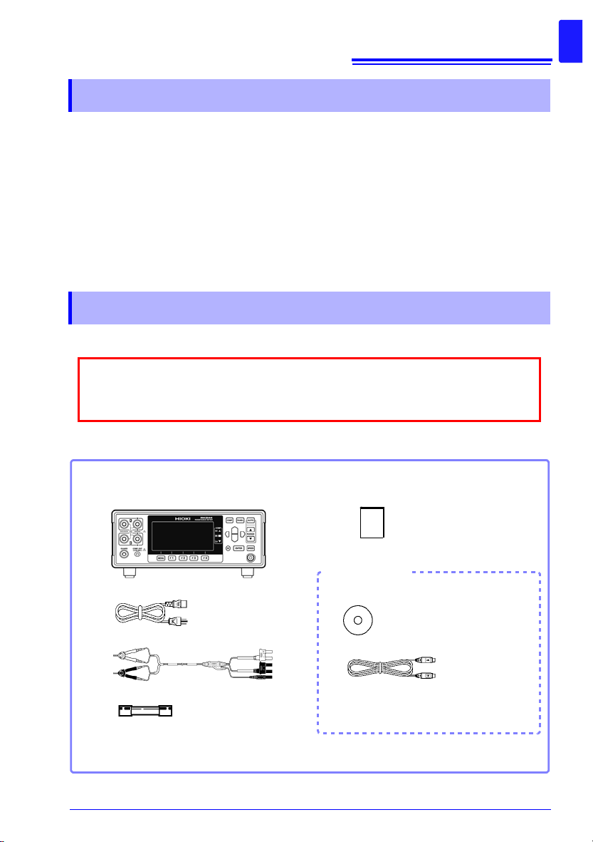
Confirm that these contents are provided.
Model RM3544 or RM3544-01..................1
Power Cord (2-line + ground) (p. 25) ........1
Model L2101 Clip Type Lead ................... .1
Spare Fuse (F500mAH/250V)...................1
Instruction Manual (This document)...1
* The latest version of the application disc can be downloaded from the Hioki web site.
Application disc (CD)*.........................1
(Communications Command
Instruction Manual , USB drive r)
USB cable (A-B type) .........................1
EXT I/O Male Connector (p. 119).......1
RM3544-01 only
Introduction
Thank you for purchasing the HIOKI Model RM3544/ RM3544-01 Resistance Meter.
To obtain maximum performance from the instrument, please read this manual first, and
keep it handy for future reference.
Model RM3544-01 is the same as the RM3544, but with USB, RS-232C, and EXT I/O
included.
Registered tradem ar ks
Windows is a registered trademark of Microsoft Corporation in the United States and/or
other countries.
Verifying Package Contents
Inspection
1
Content confirmation
2
Measurement
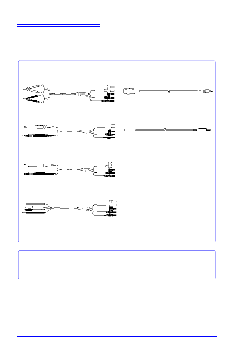
Model L2101 Clip Type Lead
Model L2102 Pin Type Lead
Model L2103 Pin Type Lead
Model L2104 4-Terminal Lead
Interface Cables
Model 9637 RS-232C Cable (9pin-9pin/ 1.8 m/ crossover cable)
Model 9638 RS-232C Cable (9pin-25pin/ 1.8 m/ crossover cable)
Model L2105 LED Comparator Attachment
Model Z2001 Temperature Sensor
Verifying Package Contents
Options
Contact your authorized Hioki distributor or reseller for details.
See: "Appendix 13 Measurement Leads (Options)" (p. A27)
Safety Information
Safety Information
This instrument is designed to conform to IEC 61010 Safety Standards, and has been thoroughly tested for safety prior to shipment.
However, using the instrument in a way not described in this manual may negate the provided safety features.
Before using the instrument, be certain to carefully read the following safety notes.
Mishandling during use could result in injury or death, as well as damage to the product. Be certain that you understand the instructions and
precautions in the manual before use.
With regard to the electricity supply, there are risks of electric shock,
heat generation, fire, and arc discharge due t o shor t circ ui ts. If persons
unfamiliar with electricity measuring instruments are to use the product, another person familiar with such instruments must supervise
operations.
This manual contains information and warnings essential for safe operation of the instrument and for maintaining it in safe operating condition. Before using it, be sure to carefully
read the following safety precautions.
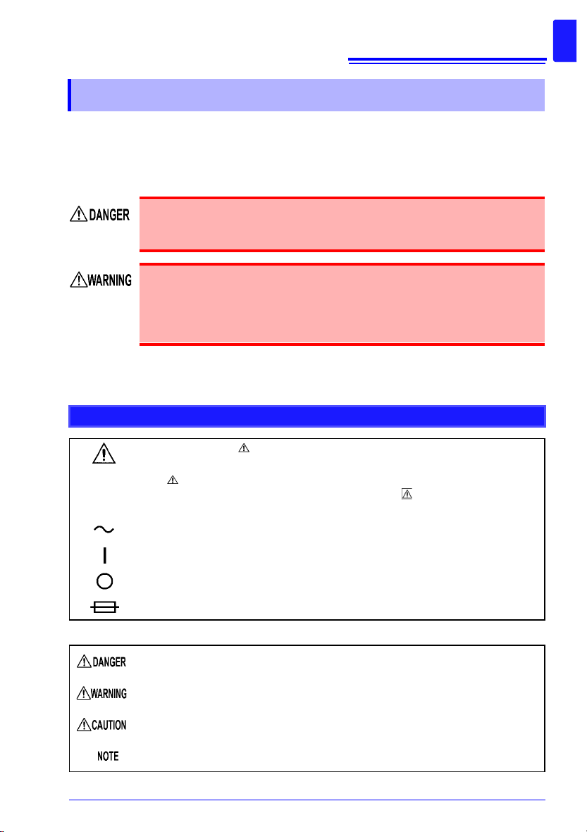
Safety Symbols
3
In the manual, the symbol indicates particularly important information that the
user should read before using the instrument.
The symbol printed on the instrument indicates that the user should refer to a
corresponding topic in the manual (marked with the symbol) before using the
relevant function.
Indicates AC (Alternating Current).
Indicates the ON side of the power switch.
Indicates the OFF side of the power switch.
Indicates a fuse.
The following symbols in this manual indicate the relative importance of cautions and warnings.
Indicates that incorrect operation presents an extreme hazard that could result in
serious injury or death to the user.
Indicates that incorrect operation presents a significant hazard that could result in
serious injury or death to the user.
Indicates that inc o rr ect op er ati on pre s ents a po ss ib ili ty of i n jur y to th e use r or dam age to the instrument.
Indicates advisory ite ms relate d to perform ance or cor rect oper ation of th e instrument.
4
Safety Information
Symbols for Various Standards
This symbol indicates that the product conforms to regulations set out by the EC
Directive.
WEEE marking:
This symbol indicates that the electrical and electronic appliance is put on the EU
market after August 13, 2005, and producers of the Member States are required to
display it on the appliance under Article 11.2 of Directive 2002/96/EC (WEEE).
Other Symbols
Indicates the prohibited action.
(p. )
[ ]
SET
(Bold characters)
Unless otherwise specified, “Windows” represents Windows XP, Windows Vista, Windows 7, or
Windows 8.
Accuracy
We define measurement tol erances in terms of f.s. (full scale ), rdg. (read ing) and dgt. (di git) values, w ith the
following meanings.
f.s.
rdg.
dgt.
See: "Example accuracy calculations" (p. 148)
Indicates the location of reference information.
*
Indicates that descriptive information is provided below.
Square brackets indicate instrument display labels (such as setting item names).
Bold characters within the text indicate operating key labels.
(maximum display value)
This is usually the name of the maximum displayable value. For this instrument, it
indicates the currently selected range.
(reading or displayed value)
The value currently being measured and indicated on the measuring instrument.
(resolution)
The smallest displayable unit on a digital measuring instrument, i.e., the input value
that causes the digital display to show a “1” as the least-significant digit.
Operating Precautions
Operating Precautions
Follow these precautions to ensure safe operation and to obtain the full benefits of the various functions.
Preliminary Checks
Before using the instrument for the first time, verify that it operates normally to ensure that
no damage occurred during storage or shipping. If you find any damage, contact your
authorized Hioki distributor or reseller.
Before using the instrument, make sure that the insulation on the
power cord, leads or cables is undamaged and that no bare conductors
are improperly exposed. Using the instrument in such conditions could
cause an electric shock, so contact your authorized Hioki distributor or
reseller for replacements.
5
6
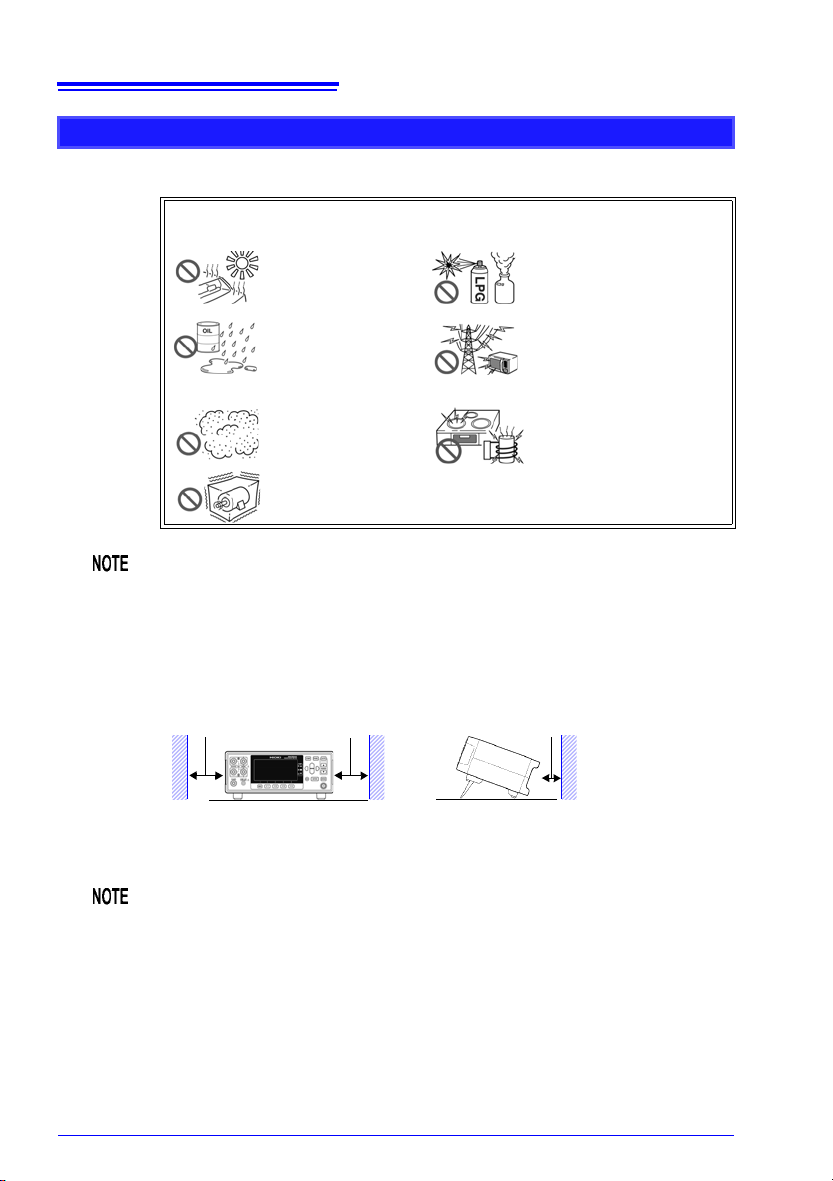
10 mm or more
Rear
50 mm or more 50 mm or more
The instrument can be used with the stan d (p. 18).
It can also be rack-mounted. (p. A28).
Operating Precautions
Instrument Installation
Operating temperature and humidity : 0 to 40°C at 80% RH or less (non-condensating)
Storage temperature and humidity : -10°C to 50°C at 80% RH or less (non-condensating)
Avoid the following locations that could cause an accident or damage to the
instrument.
Correct measurement may be impossible in the presence of strong magnetic
fields, such as near transformers and high-current conduct or s, or i n the presence of strong electromagnetic fields such as near radio transmitters.
Exposed to direct sunlight
Exposed to h igh temp erature
Exposed to water, oil,
other chemicals, or s olvents
Exposed to high humidity or condensation
Exposed to high levels
of particulate dust
Subject to vibration
In the presence of corrosive or
explosive gases
Exposed to strong electromagnetic fields
Near electromagnetic radiators
Near induction heating systems
(e.g., high-frequency induction heating systems and IH
cooking utensils)
Installation Precautions
• The instrument should be operated only with the bottom downwards.
• Do not place the instrument on an unstable or slanted surface.
Unplugging the power cord kills power to the instrument. Be sure to provide
enough unobstructed space to unplug the power cord immediately in an
emergency.
Handling the Instrument
• Do not allow the inst ru men t to get w e t, and do not take measurements
with wet hands. This may cause an electric shock.
• Do not attempt to modify, disassemble or repair the instrument; as
fire, electric shock and injury could result.
• To avoid damage to the instrument, protect it from physical shock when
transporting and handling. Be especially careful to avoid physical shock
from dropping.
• To avoid damage to the instrument, do not apply voltage or current to mea-
surement terminals, TEMP.SENSOR jack, or COMP.OUT jack.
• This instrument may cause interference if used in residential areas. Such
use must be avoided unless the user takes special measures to reduce
electromagnetic emissions to prevent interference to the reception of radio
and television broadcasts.
• Use the original packing materials when transporting the instrument, if pos-
sible.
Handling the Cords and Leads
7
Operating Precautions
To avoid electrical shock, be careful t o avoid shorting live lines with the
test leads.
• Avoid stepping o n or pinching cables, which could damage t he cable insul a-
tion.
• To avoid breaking cables or lead wires, do not bend or pull them.
• To avoid damaging the power cord, grasp the plug, not the cord, when
unplugging it from the power outlet.
• To avoid damaging the cable, grasp the connector, not the cable, when
unplugging the cable.
• The ends of the pin type lead are sharp. Be careful to avoid injury.
• Keep the cables well away from heat sources, as bare conductors could be
exposed if the insulation melts.
• Temperature sensors are precision devices. Be aware that excessive volt-
age pulses or static discharges can destroy the film.
• Avoid subjecting the temperature sensor tip to physical shock, and avoid
sharp bends in the leads. These may damage the probe or break a wire.
8
Operating Precautions
• Use only the specified cords and leads. Using a non-specified cord or lead
may result in incorrect measurements due to poor connection or other reasons.
• If the part of the temperature sensor that connects to the instrument
becomes dirty, wipe it clean. The presence of dirt may affect temperature
measured values by increasing the contact resistance.
• Exercise care so that the temperature sensor connector does not become
disconnected. (If the sensor is disconnected, it will not be possible to perform temperature correction.)
CD-R disc precautions
• Exercise care to keep the recorded side of discs free of dirt and s cratches.
When writing text on a disc’s label, use a pen or marker with a soft tip.
• Keep discs inside a protective case and do not expose to direct sunlight,
high temperature, or high humidity.
• Hioki is not liable for any issues your computer system experiences in the
course of using this disc.
Before Connecting the Power Cord
• To avoid electrical accidents and to maintain the safety specifications
of this instrument, connect the power cord provided only to a 3-contact (two-conductor + ground) ou tl et .
• Use only the design ate d power cord with this instrument. Use of other
power cords may cause fire.
• Before using the instrument, make sure that the insulation on the
power cord is undamaged and that no bare conduct ors are impr operly
exposed. Any damage could cause electric shock, so contact your
authorized Hioki distributor or reseller.
To avoid damaging the power cord, grasp the plug, not the cord, when
unplugging it from the power outlet.
Before Connecting Measuremen t Leads
To avoid shock and short circuits, turn off all power before connecting
measurement leads.
Before Connecting the LED Comparator Attachment
• To keep from damaging the instrument or LED Comparator Attachment,
turn off the instrument before connecting the attachment.
• The COMP.OUT jack is provided exclusively for use with the L2105. Do not
connect any device other than the L2105.
• The attachment may not fulfill the specifications if the connector is not
attached securely.
• Do not over-tighten the cable tie around the measurement leads. Doing so
may damage the measurement leads.
• Avoid the following as damage to the cable conductor or insulation may
result:
Twisting or pulling on cables
Bending cables near the lamp excessively in order to connect them
Before Connecting the Temperature Sensor
Failure to fasten the connectors properly may result in sub-specification performance or damage to the equipment.
Note the following precautions to avoid damaging the instrument:
• To keep from damaging the instrument or temperature sensor, turn off the
instrument’s main power switch before connecting the sensor.
• Connect the temperature sensor by inserting the plug all the way into the
TEMP.SENSOR jack. A loose connection can cause a large error component in measured values.
9
Operating Precautions
If the temperature sensor jack becomes dirty, wipe it clean. The presence of
dirt will cause an error in temperature measured values.
10
Operating Precautions
Before Connecting Data Cables (US B, RS-232C)
Observe the following precautions when connecting the instrument and a
controller:
• To avoid faults, do not disconnect or reconnect the USB cable during instru-
ment operation.
• The USB and RS-232C interfaces are not isolated from the ground circuit.
Connect the instrument and the controller to a common earth ground.
Using different grounds could result in potential difference between the
instrument and the controller. Potential difference on the data cable can
result in malfunctions and faults.
• Before connecting or disconnect ing the RS- 232C Cabl e, always tu rn off the
instrument and the controller. Failure to do so could result in equipment
malfunction or damage.
• After connecting the RS-232C Cable, tighten the screws on the connector
securely. Failure to secure the connector could result in equipment malfunction or damage.
Before Connecting the Printer
Because electric shock and instrument damage hazards are present,
always follow the steps below when connecting the printer.
• Always turn off the instrument and the printer before connecting.
• A serious hazard can occur if a wire becomes dislocated and contacts
another conductor during operation. Make certain connections are
secure.
Operating Precautions
Before Switching between Current Sink (NPN) and Current Source (PNP)
• Configure the NPN/PNP setting to accommodate externally connected
equipment.
• Do not operate the NPN/PNP switch while the instrument is on.
Before Connecting EXT I/O
To avoid electric shock or damage to the equipment, always observe
the following precautions when connecting to the EXT I/O connect or.
• Always turn off the main power switch on the instrument and on any
devices to be connected before making connec tions.
• Be careful to avoid exceeding the ratings of external terminals (p.
106).
• During operation, a wire becoming dislocated and contacting another
conductive object can be serious hazard. Use screws to secure the
external connectors.
• The ISO_5V pin of the EXT I/O connector is a 5V (NPN)/ -5V (PNP)
power output. Do n ot apply ext ernal power t o thi s pin. (Exte rnal p owe r
cannot be supplied to the instrument’s EXT I/O connector.)
11
To avoid damage to the instrument, observe the following cautions:
• Do not apply voltage or current to the EXT I/O terminals that exceeds their
ratings.
• When driving relays, be sure to install diodes to absorb counter-electromo-
tive force.
• Be careful not to short-circuit ISO_5V to ISO_COM.
• Configure the NPN/PNP setting to accommodate externally connected
equipment.
• Do not operate the NPN/PNP switch while the instrument is on.
See: "Connector Type and Signal Pinouts" (p. 91)
Before Turning Power On
Before turning the instrument on, make sure the supply voltage
matches that indicated on its power connector. Connection to an
improper supply voltage may damage the instrument and present an
electrical hazard.
Avoid using an uninterruptible power supply (UPS) or DC/AC inverter with
rectangular wave or pseudo-sin e-wave output t o power t he instru ment. Doing
so may damage the instrument.
12
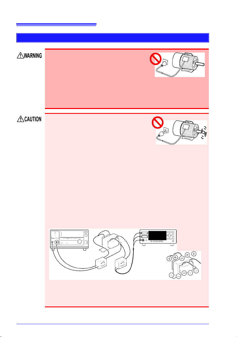
The measurement target is
connected to a power supply.
• Never attempt to measure at a point where volt-
age is present. Even if the power supply to the
motor is turned off, while the motor is rotating
inertially, high electromotive power is generated
in terminals. When attempting to measure a
transformer or motor immediately after voltage
withstanding test, induced voltage or residual
charge may damage the instrument.
Rotating inertially
• When the RM3544 is used in a way that connects to a withstanding voltage
tester via switching relays, construct a testing line bearing the following in
mind.
See: "Appendix 12 Using the Instrument with a Withstanding Voltage Tester" (p.
A26)
(1) The voltage withstanding specification of switching relays should
include a safe margin over the withstanding testing voltage.
(2) To protect against damage due to arc discharge in relay contacts, all
RM3544 measurement terminals should be grounded during voltage
withstanding testing.
(3) To protect against damage due to residual charge, measure resistance
first, and voltage withstanding last.
3158 AC Withstanding Voltage HiTester
Withstand voltage of relay switch is not high enough.
Residual charge from voltage
withstanding test is present.
RM3544
Operating Precautions
Before Measuring
• To avoid electric shock or damage to the
instrument, do not apply voltage to the
measurement terminals. Also, to avoid
electrical accidents, only take measurements after turning off the power to the
measurement targets being measured.
• Sparks may result at the moment the instrument is connected to, or
disconnected from, the measurement target. To avoid fire or bodily
injury, avoid use in the presence of explosive gases.
• Battery internal resistance cannot be measured with this instrument. It will
sustain damage. To measure battery internal resistance, we recommend the
HIOKI 3554, 3555, BT3562, BT3563 and 3561 Battery HiTesters.
• When measuring devices such as power supply transformers with high
inductance or open-type solenoid coils, measured value may be unstable.
In such cases, connect a film capacitor of about 1 F between SOURCE A
and SOURCE B.
• Carefully insulate all SOURCE A, SENSE A, SENSE B, and SOURCE B
wiring. Proper 4-terminal measurements cannot be performed and an error
will occur if core and shield wires touch.
• The SOURCE terminal is protected by a fuse. If the fuse is tripped, the
instrument will display “
Blown Fuse.” and you will not be able to measure
resistance values. If the fuse is tripped, replace the fuse.
See: "12.2 Replacing the Measurement Circuit’s Protective Fuse" (p. 171)
When using the temperature sensor
The temperature sensor is not waterproof. Do not submerse it in water or
other liquid.
• Allow the measurement target for which temperature correction is being
performed and the temperature sensor to adjust to the am bient temper ature
prior to measurement. Failure to do so will result in a large error component.
• Handling of the temperature sensor with bare hands may cause the sensor
to pick up inductive noise, resulting in unstable measured values.
• The temperature sensor is designed for use in applications in which ambi-
ent temperature is measured. It is not possible to accurately measure the
temperature of the measurement target itself by placing the sensor in contact with the surface of the target.
• Connect the temperature sensor by inserting the plug all the way into the
TEMP.SENSOR jack. A loose connection may cause a large error component in measured values.
13
Operating Precautions

14
Operating Precautions

15
• Installed footprint: 215 mm × 166 mm
Compact footprint and limited depth leave plenty of work space in front of the instrument.
• Measurement range: 30.000 m to 3.0000 M with a basic accuracy of 0.02%
rdg.
• Maximum measurement current: 300 mA
Ensures stable measurem ent, even when there is a significant amount of exter na l noise.
• No need for warm-up operation or zero-adjustment
Since wasteful wait t im es a re not required, you can s t ar t m aki ng measurements as soon as
the instrument is turned on.
• Choice of interfaces
RM3544 (no interface), RM3544-01 (USB, RS-232C, EXT I/O)
Compact yet reliable specifications
1.1 Product Overview and Features
Overview Chapter 1
1.1 Product Overview and Features
The RM3544 is capable of performing high-speed, high-precision measurement of the
winding resistance of components such as motors and transformers, the contact resistance
of relays and switches, the pattern resistance of printed circuit boards, and the DC resistance of fuses, resistors, and materials such as conductive rubber using four-terminal measurement. Since the instrument incorporates a temperature correction function, it is
particularly well suited to the measurement of targets whose resistance values vary with
temperature.
1
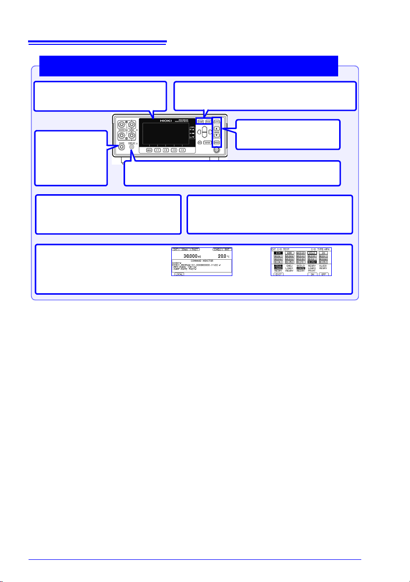
16
LED Comparator Attachment (option)
Streamlines work by eliminating the need to look at the screen.
Graphical LCD
Operation is intuit ive and easy to l earn.
Easy configuration of comparator and panel
load operation
Facilitates smooth se tup changes o n production lines.
Simple basic settings
Range and measurement
speed can be set directly.
Guard terminal
You can reduce the
effects of external
noise by connecting the guard terminal.
Free power supply (100 to 240 V) with
automatic frequency switching
Allows the instrument to be easily moved to
overseas production lines.
Judgment sounds with user-selectable patterns
Keeps you from mistaking audio from a
nearby operator ’s instrument as your own.
Easy-to-use functions in research and development,
on production lines, or in acceptance inspections
Monitor and test functions
Provides robust support for line development by allowing you to check
communications and E XT I/ O on th e
screen.
Example communic ations
monitor screen
Example EXT I/O test
screen
1.1 Product Overview and Features
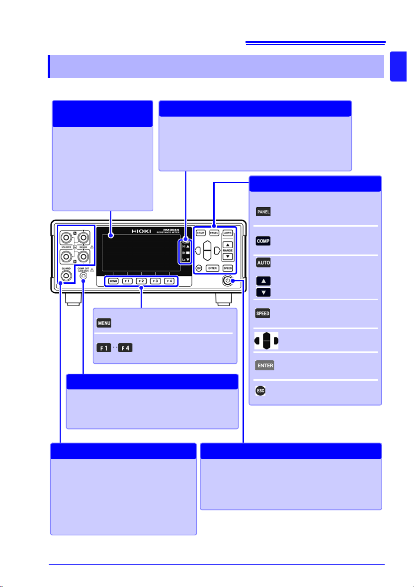
17
Display Screen (Monochrome graphical LCD)
Display of measuremen ts and
settings (p. 21)
Viewing Measured
Values and Settings
COMP indicator LEDs
Indicate the judgment result of the measured value (p.60).
Hi Measured value is above upper limit
IN Pass (meets criteria)
Lo Measured value is below lower limit
Viewing Comparator Results
MENU key
Switching of F key pages
F keys
Selection of settings displayed
on the screen
COMP.OUT jack
Connect the L2105 LED Comparator Attachment to
view judgment re sults without needing to refe r to the
instrument display. (p.70)
Connecting the LED Compa rator Att achment
PANEL key
Saving and loading of panels
(p.72)
COMP key
Configuration of comparator
settings (p.60)
AUTO, RANGE key
Range switching (p.32)
SPEED key
Measurement speed switch ing
(p.33)
Cursor keys
Selection of settings and digits
ENTER key
Acceptance of settings and
manual trigger input
ESC key
Cancellation of operation
Settings
Measurement T erminals
Connect measurement leads (p. 26).
• SOURCE A : Current detection terminal
• SOURCE B : Current source terminal
• SENSE A : Voltage detection terminal
• SENSE B : Voltage detection terminal
• GUARD : Guard terminal
Connecting Measurement Leads
STANDBY Key: Initiates or cancels the
standby stat e. (p . 28) .
• Unlit: power off (when no power supplied)
• Red light: Standby State (while power is supplied)
• Green light: power on
Initiating and Canceli ng the Standby State
1.2 Names and Functions of Parts
1.2 Names and Functions of Parts
Front Panel
1
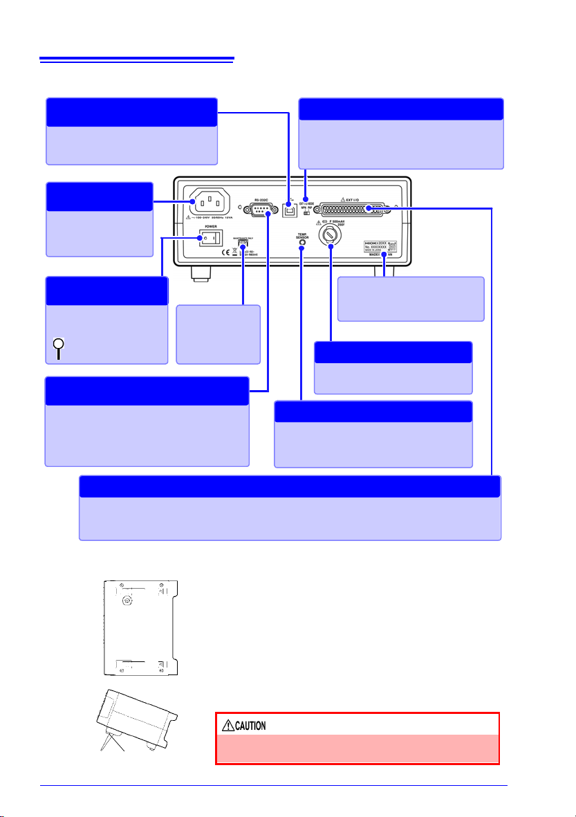
18
TEMP.SENSOR jack
Connect the Z2001 Temperature Sensor
when using temperature correction (p.27).
Correcting Temperature
RS-232C connector
• Connect to a computer, PLC, or other
device (p.126).
• Connect to a printer (p.137).
RS-232C Communications
Printer Output
Fuse holder (p.171)
Replacing the Fuse
Main power switch
(p.28)
: Main power off
: Main power on
Turning the Main
Power On and Off
EXT I/O connector
Connect when controlling the instrument with a PLC, I/O board, or other equipment to allow measurement to be started and measured values and comparator results to be acquired (p. 89).
External Control
Manufacturer's Serial No.
Do not remove this label, as it is
required for product support.
Power Inlet
Connect the supplied
power cord (p.25).
Connecting the
Power Cord
EXT I/O NPN/PNP switch
Left : Current sink (NPN)
Right : Current source (PNP)
Switching between NPN and PNP
USB jack
Connect to a computer (p.123).
Sending and Receiving
Data via USB
Maintenance
terminal
Do not use.
Bottom Panel
Stand
When using the stand
Extend the legs all the way. Do not extend partially.
Make sure to extend both legs of the stand.
Collapsing the stand
Do not collapse the sta nd partway. Be sur e to collapse it
all the way.
This instrument can be rack mounted.
See: "Appendix 14 Rack Mounting" (p. A28)
Parts removed f rom th is inst rumen t sh ould be sto red
in a safe place to enable future reuse.
Do not apply heavy downward pressure with the
stand extended. The stand could be damaged.
1.2 Names and Functions of Parts
Rear Panel
19
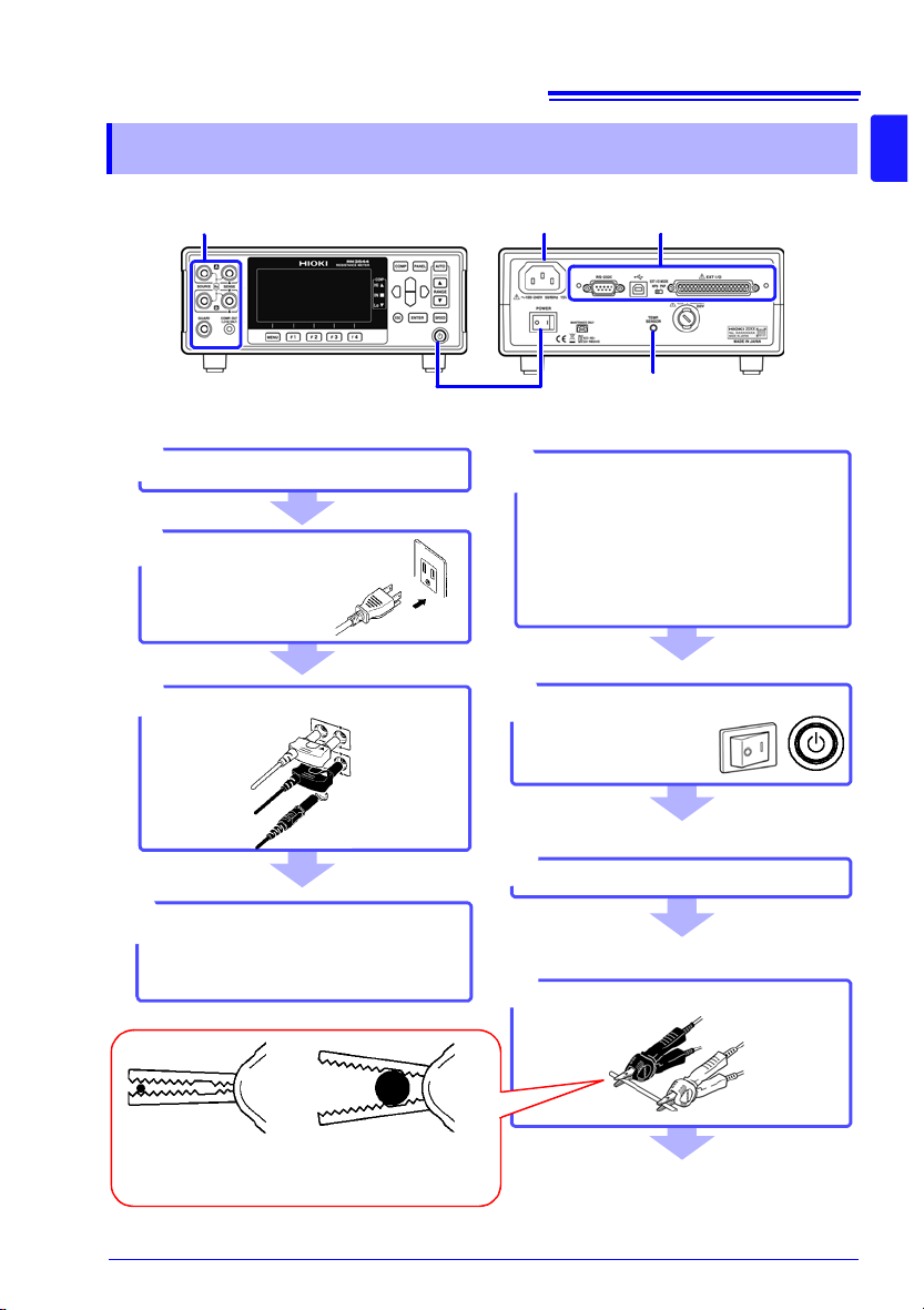
Install this instrum e nt (p. 5)
1
Rear Panel
Tu rn on the instrument and cancel
the standby state
(p.28)
6
When finished measuring, turn the
power off (p.28).
Connect the temperature sensor
(p.27)
(When using the temperature correction function)
4
2
3
Make instrument settings
*1
Connect measurement leads (p.26)
7
Connect to the test sample (p.34)
8
Connect the power
cord (p.25)
Connect the external interface
(RM3544-01; as necessar y)
5
• Using the printer (p.137)
• Using the USB or RS-232C inter-
face (p.121)
• Using the EXT I/O (p.89)
When clipping a small-gauge
wire
(Clip with the tip of the alligator
clips.)
When clipping a large-gauge
wire
(Clip with the back of the alligator
clips, where there are no teeth.)
6
3
4
2
5
Front Pane l
Rear Front
1.3 Measurement Process
1.3 Measurement Process
1

20
1.3 Measurement Proces s
*1 About zero-adjustment
Perform zero-adjustment in the following circumstances:
• The measured value is not cleared due to thermal EMF or other factors.
The measured value will be adjusted to zero. (Accuracy is not affected by whether or
not the zero adjustment is performed.)
• Four-terminal connection (called Kelvin connection) is difficult.
The residual resistance of the two-terminal connection wires will be canceled.
See: "4.1 Zero Adjustment" (p.44)
"Appendix 6 Zero Adjustment" (p.8)
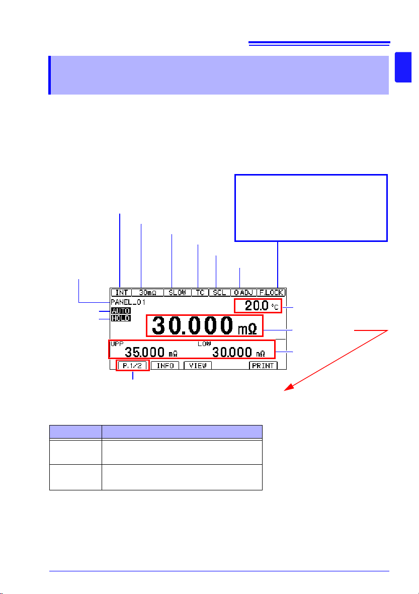
21
Trigger source (INT/EXT)
Measurement range
TC (ON)
0ADJ (ON)
Auto range
Key lock state or remote state
Cancel the key lock state or remote
state by pressing and ho lding the
MENU key.
F.LOCK : All operations prohibited .
M.LOCK: Menu operations prohibited.
RMT : Remote state
Judgment value
Switched with the VIEW key
(No display / temperature /
pre-calculation resistance
value)
Page switching
Measurement scre en la yo u t
Hold state
Scaling (ON)
Measurement speed
Number and name
of loaded panel
Measured value
1.4 Screen Organization and Operation Overview
1.4 Screen Organization and
Operation Overview
The instrument’s screen interface consists of a Measurement screen and various Settings
screens.
The screen examples in this guide appear reversed (black on white) for best visibility on the
printed page. However, the instrument screens can actually be displayed only as white
characters on black background.
1
Display of information other than measured values
(For more information, see "Confirming Measurement Faults" (p.38).)
* To treat current faults (when the source wiring is open) as over-range events, change the
Display Description
+OvrRng
-OvrRng
- - - - -
current fault output mode setting. (p.40)
Over-range
Not measured, or broken conn ection in measurement target *
22
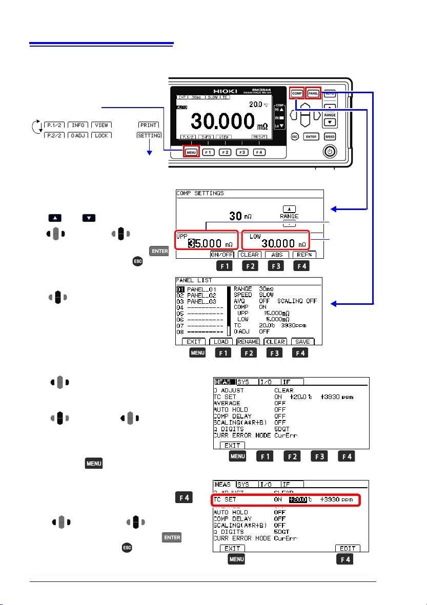
Overview of screen operation
Menu switching
(4) To Settings screens
(1) Measurement screen
(2) Comparator Settings screen
Upper limit
value
Lower limit
value
(3) Panel Save/Load screen
Select a panel number.
3
Change
values.
Move among
digits.
Accept the setting with the
key or cancel with the key.
4
Change the range with the
and keys.
2
1
2
Perform action with an F key.
1
Select the mode with an F key.
(4) Settings screen
< Setting values >
Make the value editable with the
key.
2
Change values.
1
Move among
digits.
Accept the setting with the key
or cancel with the key.
3
Return to the Measurement screen
with the key.
Move to the [M EAS], [SYS], [I/ O],
or [IF] tab.
([I/O] and [IF] tabs: RM3544-01 only.
Not shown on RM3544.)
1
2
Select a
setting.
Move among
settings.
Switch functions with an F key or set
values.
3
4
1.4 Screen Organization and Operation Overview
 Loading...