


PW9005
HIOKI PW9005A980-07
GPS ボックス
GPS BOX
取扱説明書
Instruction Manual
Mar. 2023 Revised edition 7
PW9005A980-07
JA/EN
[600339727]

目 次
はじめに................................................................................................................1
HIOKI PW9005A980-07
梱包内容の確認..................................................................................................1
安全について ......................................................................................................2
ご使用にあたっての注意...............................................................................3
第 1 章
概要 ___________________________________________5
1.1 製品概要 ............................................................................................5
1.2 各部の名称と機能 ......................................................................... 5
第 2 章
PQ3198 と接続する ____________________________7
2.1 測定前の点検 ..................................................................................7
2.2 接続の手順 .......................................................................................8
第 3 章
PQ3198 で GPS の設定をする
(GPS 状態を確認する ) ________________________ 11
i
目次
第 4 章
PQ3198 の GPS 測位と時刻補正について ______ 15
第 5 章
仕様 _________________________________________ 19
PW9005A980-07
3.1 接続先を GPS に設定する ....................................................12
3.2 タイムゾーンを設定する ........................................................13
3.3 GPS 状態を確認する ...............................................................14
3.4 GPS マーク ( 測位状態・エラー状態の表示 ) .............14
4.1 GPS 測位 .......................................................................................15
4.2 時刻補正処理 ...............................................................................17
4.3 GPS イベント機能 ....................................................................17

ii
HIOKI PW9005A980-07
目次
第 6 章
保守・点検 ____________________________________21
6.1 交換部品と寿命について .......................................................21
6.2 本器を廃棄する .......................................................................... 22
6.3 困ったときは ............................................................................... 23
はじめに
HIOKI PW9005A980-07
はじめに
このたびは、HIOKI PW9005 GPS ボックス をご選定いただき、誠にありがとうございま
す。この製品を十分にご活用いただき、末長くご使用いただくためにも、取扱説明書はて
いねいに扱い、いつもお手元に置いてご使用ください。
PW9005 GPS ボックスを以降「本器」と記載します。
取扱説明書の最新版
取扱説明書の内容は、改善・仕様変更などのために変更する場合があり
ます。
最新版は、弊社ウェブサイトからダウンロードできます。
https://www.hioki.co.jp/jp/support/download/
製品ユーザー登録のお願い
製品に関する重要な情報をお届けするために、ユーザー登録をお願いし
ます。
https://www.hioki.co.jp/jp/mypage/registration/
梱包内容の確認
1
本器がお手元に届きましたら、輸送中において異常または破損がないか点検してからご使
用ください。特に付属品および、端子類に注意してください。
おり動作しない場合は、お買上店(代理店)か最寄りの営業拠点にご連絡ください。
本体 • GPS ボックス
付属品 • GPS アンテナ ( 約 5 m)
本器を輸送するときは
本器を輸送する場合は、お届けしたときの梱包材料をご使用ください。
輸送中に破損しないように梱包し、故障内容も書き添えてください。輸送中の破損につい
ては保証しかねます。
万一、破損あるいは仕様ど
• RS-232C ケーブル
• 取扱説明書 ( 本書 )
2
HIOKI PW9005A980-07
安全について
安全について
この取扱説明書には本器を安全に操作し、安全な状態に保つのに要する情報や注意事項が
記載されています。本器を使用する前に、次の安全に関する事項をよくお読みください。
この機器は IEC 61010 安全規格に従って、設計され、試験し、安全な状
態で出荷されています。測定方法を間違えると人身事故や機器の故障につ
ながる可能性があります。また、本器をこの取扱説明書の記載以外の方法
で使用した場合は、本器が備えている安全確保のための機能が損なわれる
可能性があります。
取扱説明書を熟読し、十分に内容を理解してから操作してください。万一
事故があっても、弊社製品が原因である場合以外は責任を負いかねます。
取扱説明書の注意事項には、重要度に応じて次の表記がされています。
操作や取り扱いを誤ると、使用者が死亡または重傷につながる危険性
が極めて高いことを意味します。
操作や取り扱いを誤ると、使用者が死亡または重傷につながる可能性
があ
ることを意
操作や取り扱いを誤ると、使用者が傷害を負う場合、または機器を損
傷す
る可能性が
製品性能および操作上でのアドバイスを意味します。
味します。
あることを意味します。
安全記号
規格に関する記号
直流(DC)を示します。
EU 指令が示す規制に適合していることを示します。

ご使用にあたっての注意
HIOKI PW9005A980-07
ご使用にあたっての注意
• 本器を安全にご使用いただくために、また機能を十二分にご活用いただくために、次の
注意事項をお守りください。
• 本器の仕様だけではなく、使用する付属品、オプションなどの仕様の範囲内で本器をご
使用ください。
設置環境
3
保存温湿度範囲本体 : -20
GPS アンテナ : -40
使用温湿度範囲本体 : 0
°C ~ 50°C、80%rh 以下 ( 結露しないこと )
GPS アンテナ : -40
本器の故障、事故の原因になりますので、次のような場所には設置しない
でください。
• 不安定な台の上や傾いた場所に置かないでください。落ちたり、倒れた
りした場合、けがや本体の故障の原因になります。
• 底面以外の部分を下にして設置しないでください。本器の故障や火災を
引き起こす恐れがあります。
• 本器の損傷を防ぐため、運搬および取り扱いの際は振動、衝撃を避けて
ください。特に、落下などによる衝撃に注意してください。
°C ~ 50°C、80%rh 以下 ( 結露しないこと )
°C ~ 85°C( 結露しないこと )
°C ~ 85°C 40%rh ~ 95%rh
直射日光があたる場所
高温になる場所
水、油、薬品、溶剤な
どのかかる場所
多湿
、結露するような
場所
ホコリの多い場所
振動の多い場所
機械的
腐食性ガスや爆発性ガ
スが発生する場所
強力な電磁波を発生す
る場
帯電しているものの近
く
誘導加熱装置の近く
(高周波誘導加熱装置、
IH 調
所
理器具など)
本器は EN 61326 Class A の製品です。
住宅地などの家庭環境で使用すると、ラジオおよびテレビ放送の受信を妨
害することがあります。
その場合は、作業者が適切な対策を施してください。
4
HIOKI PW9005A980-07
ご使用にあたっての注意
取り扱いについて
感電事故を防ぐため、本体ケースは絶対に外さないでください。内部に
は、高電圧や高温になる部分があります。
• 本器の損傷を防ぐため、運搬および取り扱いの際は振動、衝撃を避けて
ください。特に、落下などによる衝撃に注意してください。
• UPS(無停電電源)や DC-AC インバータを使用して本器を駆動する場合
は、矩形波および擬似正弦波出力の UPS および DC-AC インバータを使
用しないでください。本器を破損することがあります。
AC アダプタについて
• ACアダプタは、PQ3198付属のZ1002 ACアダプタを必ず使用してく
ださい。AC アダプタの定格電源電圧は AC100 V ~ 240 V( 定格電源
電圧に対し ±10% の電圧変動を考慮しています)、定格電源周波数は
50/60 Hz です。機器の損傷および電気事故を避けるため、それ以外の
電圧での使用は絶対にしないでください。
• 感電事故を避けるため、また本器の安全性を確保するために、接地形 2
極コンセントに電源コードを接続してください。
使用前の確認
使用前には、保存や輸送による故障がないか、点検と動作確認をしてから使用してくださ
い。故障を確認した場合は、お買上店(代理店)か最寄りの営業拠点にご連絡ください。
• 断線防止のため、電源コードをコンセントまたは本器から抜く場合は、
差込み部分(コード以外)を持って抜いてください。
• 故障を避けるため、通信中はケーブルを抜かないでください。
• ケーブルを接続したり、取り外したりするときは、必ず PQ3198 の電源
を切ってください。誤動作や故障の原因になります。
• ケーブル接続後は、コネクターに付いているねじをしっかりと固定して
ください。コネクターの接続を確実
なります。
にしないと、誤動作や故障の原因に
第 1 章 概要
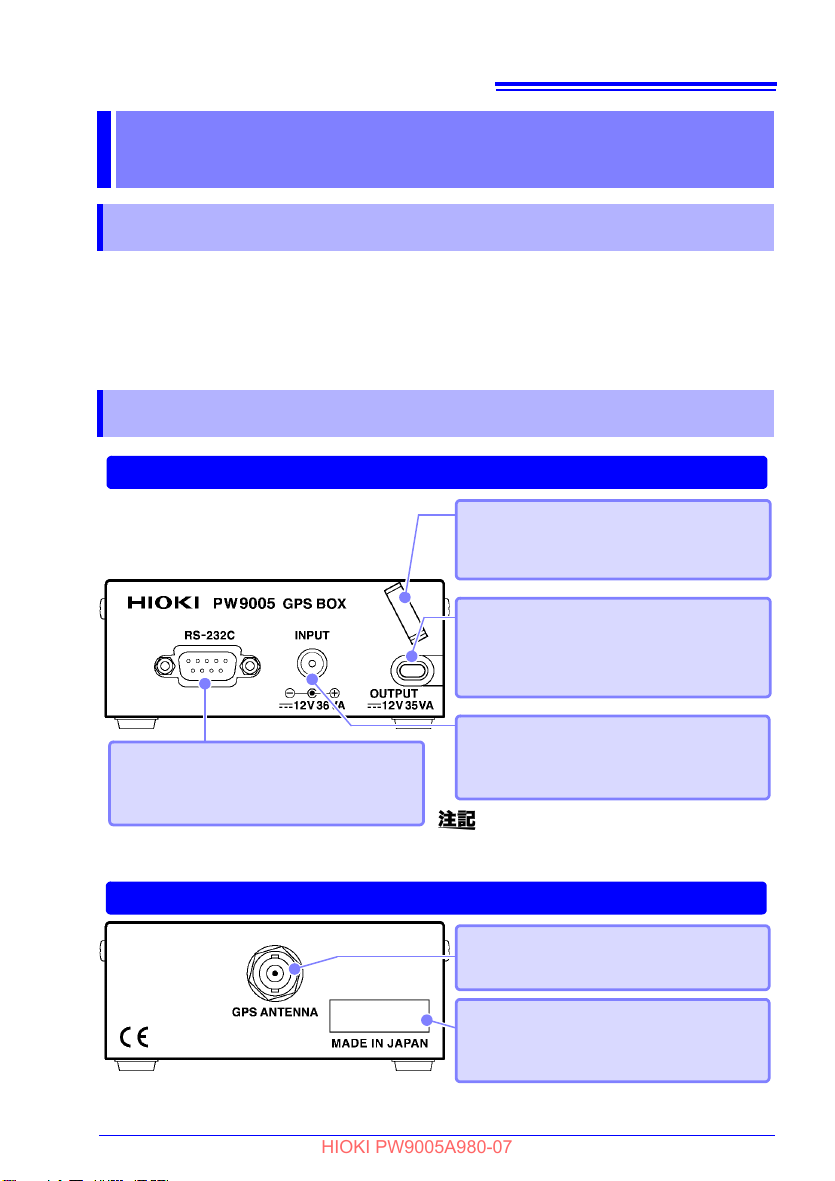
前面
背面
RS-232C インターフェイス
付属の RS-232C ケーブルを使用して、
PQ3198 に接続します。
AC アダプタ接続端子
PQ3198 付属の Z1002 AC アダプタ
を接続します。
DC 電源出力ケーブル
PQ3198 の AC アダプタ接続端子に接
続することで、PQ3198 に電源を供給
します。
アンテナ接続端子
付属の GPS アンテナを接続します。
本器には電源スイッチはありません。
AC アダプタを接続すると電源が入ります。
製造番号
製造番号を示します。管理上必要にな
りますので、はがさないでください。
ロッキングクランプ
AC アダプタのコードを通します。
(AC アダプタの抜け防止 )
HIOKI PW9005A980-07
概要 第 1 章
1.1 製品概要
本器は、PQ3198* 電源品質アナライザと組合わせて使用すると、GPS を使用した正確な
時刻を取得することができます。
本書で説明していない PQ3198 の取り扱いについては、PQ3198 付属の取扱説明書をご
覧ください。
*:PW3198 電源品質アナライザも同様に使用できます。
1.2 各部の名称と機能
5
3

6
HIOKI PW9005A980-07
第 1 章 概要
第 2 章 PQ3198 と接続する
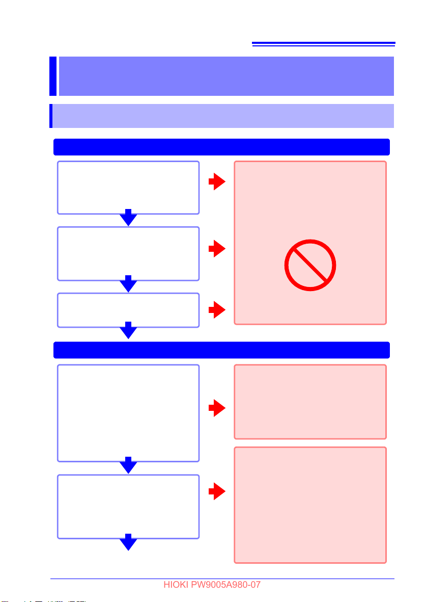
ケーブルの点検
RS-232C ケーブル・DC 電源出
力ケーブルの被覆が破れたり、金
属が露出していませんか ?
1. 接続前の点検
2. 電源投入後の点検
AC アダプタの点検
• AC アダプタに破損はないですか ?
• 電源コードの被覆が破れていま
せんか ?
本体の点検
本体に破損はないですか ?
損傷がある場合は、感電事故の原因に
なりますので、使用しないでくださ
い。
お買い上げ店 ( 代理店 ) か最寄りの
営業拠点にご連絡ください。
AC アダプタを接続したとき
参照 : P.9
• PQ3198 の電源は入りますか ?
• PQ3198 は AC アダプタ動作に
なっていますか ?
(本器には電源スイッチはありま
せん。AC アダプタを接続すると
電源が入ります )
電源コード・DC 電源出力ケーブルの
断線、AC アダプタの故障、または本
器内部が故障している可能性があり
ます。
お買い上げ店 ( 代理店 ) か最寄りの
営業拠点にご連絡ください。
OK
NG
NG
NG
OK
OK
NG
OK
PQ3198 を設定したとき
参照 : P.11
• 本器は検出されていますか ?
(PQ3198 画面上の「GPS」マ ー
クが赤色以外になっている )
付属の RS-232C ケーブル以外で接
続されている場合、正しく検出でき
ない場合があります。
付属の RS-232C ケーブル使用でも
本器が検出されない場合は、RS-
232C ケーブルが断線しているか、
PQ3198・本器内部が故障している
可能性があります。
お買い上げ店 ( 代理店 ) か最寄りの
営業拠点にご連絡ください。
NG
OK
点検完了です。
HIOKI PW9005A980-07
PQ3198 と接続する 第 2 章
2.1 測定前の点検
7
3
8
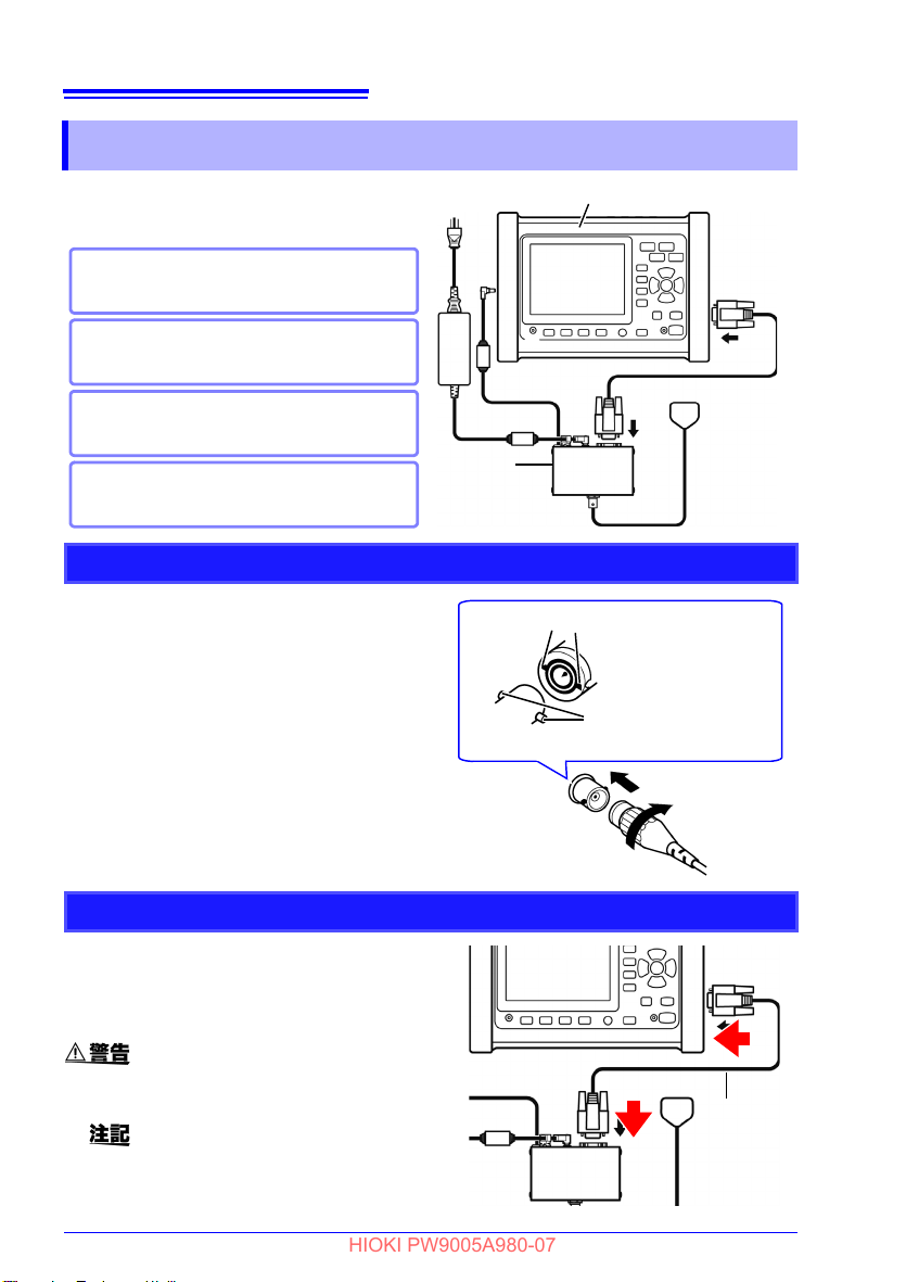
PQ3198 電源品質アナライザ
参照 :「2. RS-232C ケーブルを本器と
PQ3198 に接続する」(p.8)
参照 :「3. DC 電源出力ケーブルを
PQ3198 に接続する」(p.9)
参照 :「4. Z1002 AC アダプタを本器
に接続する」(p.9)
参照 :「1. GPS アンテナを本器に接続す
る」(p.8)
1
2
234
4
本器
接続の前に必ず「ご使用にあたっての注意」
(p.3) をよく読んでください。
1 GPSアンテナのBNCコネクタの溝を、
本体アンテナ接続端子のコネクタガイ
ドに合わせて挿し込む。
2 右へ回してロックする。
( 取外す場合は、コネクタを左に回し
てロックを解除してから、引き抜く。)
1
GPS アンテナの BNC コネクタの溝
アンテナ接続端子の
コネクタガイド
2
1 本器付属の RS-232C ケーブルを本器
とPQ3198のRS-232Cインターフェ
イスに接続する。
付属の RS-232C ケーブル以外で接続
すると、PQ3198 で正しく本器を検出
できない場合があります。
RS-232C
ケーブル
インターフェイスのコネクタの脱着時
は、各機器の電源を切ってください。
感電事故の原因になります。
HIOKI PW9005A980-07
第 2 章 PQ3198 と接続する
2.2 接続の手順
1. GPS アンテナを本器に接続する
2. RS-232C ケーブルを本器と PQ3198 に接続する
3. DC 電源出力ケーブルを PQ3198 に接続する
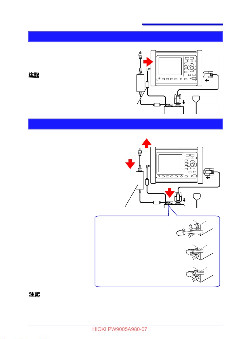
1 本器のDC 電源出力ケーブルを PQ3198
の AC アダプタ接続端子に接続する。
PQ3198 の電源を切った状態で接続
してください。
DC 電源出力ケーブル
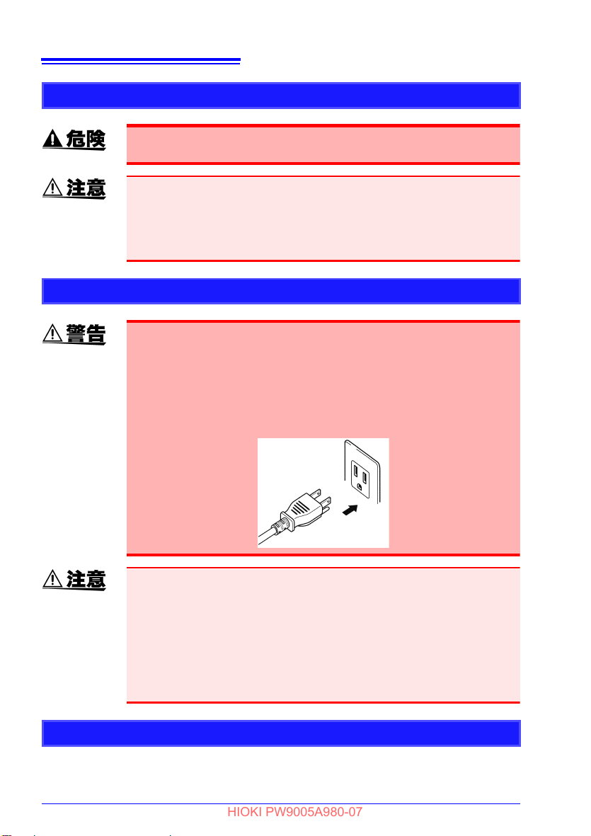
1 電源コードを AC アダプタのイン
レットに接続する。
2 AC アダプタの出力プラグを本器に
接続する。
( コード抜け防止のため、ロッキン
グクランプに AC アダプタのコード
を挟みます )
3 電源コードの入力プラグをコンセン
トに接続する。
2
3
1
1. ロッキングクランプを開く
2. ロッキングクランプに AC アダプ
タのコードを引っ掛ける
3. ロッキングクランプを閉める
• 本器には電源スイッチはありません。ACアダプタを接続すると電源が入るため、
AC アダプタは必ず最後に接続してください。
• 電源を切るときは、本器から AC アダプタを抜いてください。
Z1002 AC アダプタ
HIOKI PW9005A980-07
4. Z1002 AC アダプタを本器に接続する
第 2 章 PQ3198 と接続する
9
3

10
HIOKI PW9005A980-07
第 2 章 PQ3198 と接続する

第 3 章 PQ3198 で GPS の設定をする (GPS 状態を確認する )
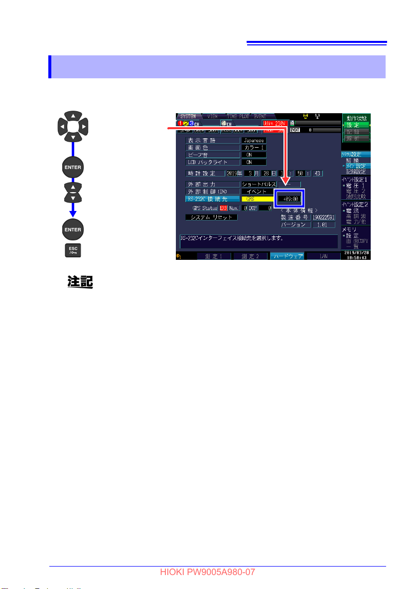
[ メイン設定 ]
[SYSTEM] 画面
[ ハードウェア ]
動作状態を[設定]に変更したいときは?
[ 記録 ] の場合 :
START/STOP キーで記録終了後、
DATA RESET キーを押す。
[ 解析 ] の場合 :
DATA RESET キーを押す。
*
HIOKI PW9005A980-07
PQ3198 で GPS の設定を
する (GPS 状態を確認す
11
る )
PW3198 を使用する場合は、 バージョン 1.07 以降と組み合わせてご使用
ください。1.06 以前のバージョンでは正常に動作しません。
PQ3198 で、GPS の設定をします。GPS の設定は本器と PQ3198 が接続された状態で
行ってください。
設定、および状態表示は下記の画面で行います。動作状態は「設定」の状態で行います。
*:PW3198 を使用する場合は、 キーになります。
第 3 章
3
12
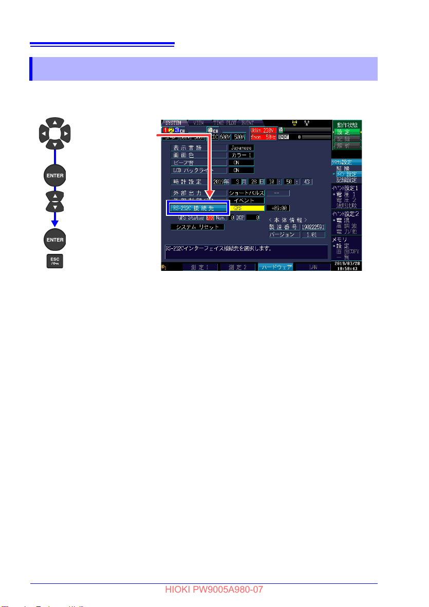
[RS-232C 接続先 ]
*
プルダウン
メニュー表示
[GPS] 選択
決定
キャンセル
HIOKI PW9005A980-07
第 3 章 PQ3198 で GPS の設定をする (GPS 状態を確認する )
3.1 接続先を GPS に設定する
RS-232C 接続先を、「GPS」に設定します。
設定後、画面上部に GPS マーク (p.14) が表示されます。
*:PW3198 では [RS 接続先 ] と表示されます。
第 3 章 PQ3198 で GPS の設定をする (GPS 状態を確認する )
[RS-232C 接続先 ]
横の枠を選択
プルダウン
メニュー表示
[+09:00] 選択
決定
キャンセル
HIOKI PW9005A980-07
3.2 タイムゾーンを設定する
タイムゾーンを設定します。協定世界時 (UTC)*からの時差を設定します。
日本で使用する場合には「+09:00」に設定します。
タイムゾーンの設定はGPSマークが黄色か青色の状態で行ってください。
GPS マークが赤色の状態で設定を行うと設定した内容が反映されません。
タイムゾーンを変更した場合、その変更内容は GPS マーク (p.14) が青色
( 時刻補正実行状態 ) になった時点で PQ3198 の内部時刻を再設定しま
す。( 再設定には数秒かかります )
GPS マークが青色になり、PQ3198 の時刻が正しく設定されていること
を確認してから、記録を開始してください。
* 協定世界時 (UTC: Coo
全世界で時刻を記録する際に使われる公式な時刻です。天体観測を元に定める GMT ( グ
リニッジ標準時 ) とほぼ同じですが、SI 単位系の 1 秒を原子時計で計測して決定してい
ます。GMT ( グリニッジ標準時 ) と協定世界時 (UTC) の差は1秒以内になるように調整
されています。
rdinated Universal Time)
13
3
14
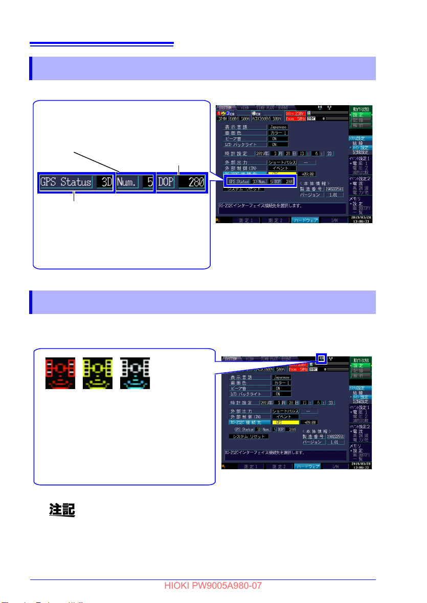
測位状態
Err : 未測位
2D : 2D 単独測位
3D : 3D 単独測位
D2D : デイファレンシャル 2D 測位
D3D : デイファレンシャル 3D 測位
測位衛星数
測位計算に使
用している衛
星個数を示し
ます。
DOP 値
0 ~ 9999
GPS の測位状態の信頼性
を示します。0 以外で小さ
い数字であるほど、信頼性
が高いことを示します。
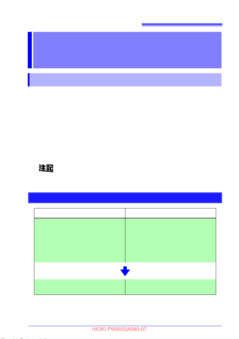
GPS の測位状態を色を変えて示します。
赤色 : PQ3198 が本器を検出できない状態
黄色 : 本器が衛星を捕捉できない、または、
測位ができない状態
記録中に時刻補正を中止した状態
青色 : 本器が衛星を捕捉して、PQ3198 が内
部時計を時刻補正を行っている状態
HIOKI PW9005A980-07
第 3 章 PQ3198 で GPS の設定をする (GPS 状態を確認する )
3.3 GPS 状態を確認する
[SYSTEM]-[ メイン設定 ]-[ ハードウエア ] 画面で GPS 状態を確認できます。
3.4 GPS マーク ( 測位状態・エラー状態の表示 )
PQ3198 の画面上部に GPS マークを表示します。
GPS マークは、RS 接続先を
GPS マークが赤色のときは、PQ3198 が本器を検出できていません。
RS-232Cケーブル、Z1002 ACアダプタの接続などを確認してください。
参照 :「2. RS-232C ケーブルを本器と PQ3198 に接続する」(p.8)、「4.
「GPS」に設定すると表示され、GPS の測位状態を示します。
Z1002 AC アダプタを本器に接続する」(p.9)
第 4 章 PQ3198 の GPS 測位と 時刻補正について
HIOKI PW9005A980-07
PQ3198 の GPS 測位と
15
時刻補正について
第 4 章
4.1 GPS 測位
GPS アンテナは上空の見晴らしが良く、周囲に障害物がないところに設置してください。
参照 :「アンテナの設置環境」(p.16)
本器の電源を初めて入れる場合や、一定期間 (1 ~ 2 週間程度 ) 使用していない場合 ( 電源
OFF の状態が続いたとき ) は、本器と PQ3198 を接続・設定後、本器が衛星捕捉して測
位状態になるまでに時間がかかることがあります。( アンテナの設置環境 (p.16) により、
数分から数十分かかることもあります )
本器が測位状態になると、PQ3198 は時刻補正を開始します。
PQ3198 の記録開始は、
さい。
時刻補正をしていない状態で PQ3198 の記録を開始すると、時系列グラ
フで記録する時刻やイベント発生時刻は、GPS を使用した時刻になりま
せんのでご注意ください。
GPS 測位の流れと GPS マークの状態について
GPS 測位の流れ GPS マークの状態
本器と PQ3198 を接続して、PQ3198
の設定を行った直後 ( 初期状態 )
参照 :「第 2 章 PQ3198 と接続する」
(p.7)、「第 3 章 PQ3198 で
GPS の設定をする (GPS 状態を確
認する )
必ず GPS マーク (p.14) が青色になってから行うようにしてくだ
黄色
」(p.11)
( 衛星を捕捉できない、または測位がで
きない状態です )
※GPS マークが赤色の場合は
PQ3198 が正しく接続できていない
可能性があります。(p.7)
、本器と
3
PQ3198 が内部時計を時刻補正開始し、
終了した状態
青色

16
HIOKI PW9005A980-07
第 4 章 PQ3198 の GPS 測位と 時刻補正について
PQ3198 の時刻補正誤差
GPS 時刻補正された状態下での、PQ3198 相互の時刻相対誤差は最大 4
m sec です。
ただし、測位状態でも DOP 値が大きい場合では測位の信頼性が低いため、
この限りではありません。
アンテナの設置環境
本器の電源を初めて入れるときや一定期間使用していないとき、測位状態
になるまでの時間は、アンテナの設置場所と GPS 衛星の位置に大きく影
響を受けます。
本器が GPS 衛星をうまく捕捉するためには、アンテナを上空の見晴らし
が良く障害物の無い場所に設置することが理想的です。逆に森林の中や高
層ビルが立ち並ぶ場所などのように、障害物が多く天頂方向しか空が開け
ていないような場所では、衛星の見通しが遮られうまく捕捉できないこと
があります。
特に、初めて電源を入れるときや一定期間使用していないときは、完全に
天空の開いた場所にアンテナを設置して衛星信号の受信を試みることが重
要です。屋内やベランダなど上空を見通せる方向が限られた場所にアンテ
ナを設置すると、電源を入れてから数十分経過しても測位状態にならない
こともあります。
また、アンテナの設置場所が建物など大きな障害物の側で、上空を見通せ
る方向が限られる場合、一度 GPS 衛星を捕捉しても衛星の移動により、時
間が経過すると未測位状態になってしまうことがあります。PQ3198 の記
録中に GP
性があります。(「4.2 時刻補正処理」(p.17) 参照 )
長期間の記録を行う場合は、上空を見通せる範囲がなるべく広い環境にア
ンテナを設置してください。
S 未測位状態が長い期間続くと、時刻補正を行えなくなる可能
GPS のロールオーバ
一般的に GPS 受信器には、ロールオーバという問題があります。これは、
年月日情報がある一定期間経過するとリセットされ、誤った年月日が出力
されるようになる現象です。
本器では、2035 年 6 月 16 日 23 時 59 分 59 秒以降は、この問題により
時刻補正が正常にできなくなります。
うるう秒の対応について
PQ3198 は、うるう秒に対応していません。
うるう秒の調整があった場合、PQ3198 が [ 設定 ] 状態以外の時は、ms
時刻補正の時刻補正範囲を超えてしまうため、GPS 時刻エラー (GPS Err)
となり、それ以降時刻補正ができなくなります。
PQ3198 が [ 設定 ] 状態の時は、通常に時刻補正が行われます。

第 4 章 PQ3198 の GPS 測位と 時刻補正について
HIOKI PW9005A980-07
4.2 時刻補正処理
PQ3198 は、測位状態のときに時刻補正を実施します。
時刻補正には、「通常時刻補正」と「ms 時刻補正」の 2 種類あり、PQ3198 の動作状態
により異なります。
17
通常時刻補正
ms 時刻補正
PQ3198 が [ 設定 ] 状態の時に実施されます。
1 秒に 1 回 PQ3198 の時刻デー
に補正します。GPS マークが青色であれば、PQ3198 は GPS 時刻
と同期した時刻で動作しています。
PQ3198 が [ 設定 ] 状態
PQ3198 の内部時計と GPS 時刻のズ
秒に 1 回 ms 単位で時刻補正を行います。
PQ3198 の内部時計精度は、0.3 秒 / 日 (23°C±5°C) です。GPS の未測
位状態が一定期間 (1 時間程度 ) 続くと、PQ3198 の内部時計が GPS 時
刻と ±16 ms 以上ずれる可能性があります。
PQ3198 の記録中に、PQ3198 の内部時計と GPS 時刻のズレが ±16 ms
より大きくなった場合は、測定データの時刻の整合性がとれなくなるた
め、GPS イベントを発生し、以後記録中の時刻補正は行いません。
(PQ3198 が記録を終了し設定状態に戻ると、「通常時刻補正」を行いま
す。)
タを GPS から取得した時刻データ
以外のとき
に実施されます。
レが ±16 ms以内の場合は、30
3
4.3 GPS イベント機能
PQ3198 では、時刻補正状態 (GPS マーク青色の
GPS の状態が変化すると次の GPS イベントを発生します。
1. GPS エラー (GPS IN)
GPS エラーが発生したことを意味します。
( 時刻補正状態(GP
2. GPS 測位 (GPS OUT)
GP
S エラーが解消したことを意味します。
( エラー状態(GP
3. GPS 時刻エラー (GPS Err)
GP
S の時刻補正不能であることを意味します。
(PQ3198 の内部時計と GP
注意事項
GPS (Global Positioning System) は、米国が開発し、同国が管理・運用する測
位システムであり、その運用によっては、GPS が保証できる測位機能は著しく劣
化することがあります。
本仕様書に記載された事項は、上記の場合を含めて保証したものではないことに注
意してください。
GPS の利用にあたっては、本システムの特性を十分に理解して、使用者の責任に
おいてその利益を活用することが重要です。
状態 ) で記録を開始した場合、記録中に
S マーク青色)からエラー状態
S マーク青色以外)から時刻補正状態
S 時刻が ±16 ms 以上ずれたとき )
(GPS マーク青色以外)になったとき )
(GPS マーク青色)になったとき )

18
HIOKI PW9005A980-07
第 4 章 PQ3198 の GPS 測位と 時刻補正について

第 5 章 仕様
HIOKI PW9005A980-07
仕様 第 5 章
19
使用場所
使用温湿度範囲
保存温湿度範囲
適合規格
無線認証
実時間補正確度
電源
電源出力
バックアップ電池寿命
インターフェイス
外形寸法
DC 電源出力ケーブル長
質量
製品保証期間
GPS 機能詳細
付属品
屋内使用、汚染度 2、高度 2000 m まで
0°C ~ 50°C、80%rh 以下 ( 結露しないこと )
GPS アンテナ -40°C ~ 85
-20°C ~ 50°C、80%rh 以下 ( 結露しないこと )
GPS アンテナ -40°C ~ 85°
安全性 EN61010
EMC EN61326
European Union and Others
EN301 489-1
EN301 489-17
EN303 413
Australia, New Zealand
AS/NZS 4268
GPS 時間確度 ±2 ms 以内 (PQ3198 本体電源 ON 時 )
Z1002 AC アダプタ (DC12 V)
定格電源電圧 : AC100 V ~ 240 V
定格電源周波数 : 50 Hz/60 Hz
予想される過度過電圧 2500 V
最大定格電力 36
DC12 V、PQ3198 専用電源 (35 VA)
約 6 年 (23°C 参考値、時刻・測位バックアップ用 )
RS-232C ( 調歩同期式シリアル )
コネクタ: D-sub 9 ピン (1 個 )
接続先 :
約 100W×40H×60D mm ( 突起物含まず )
約 1150 mm
約 330 g (GPS アンテナ除く , 本体のみ )
3 年間
1PPS 信号 : 1 秒 UTC 同期パルス
捕捉データ :
GPS アンテナ
RS-232C ケーブル ( 約 2 m)
取扱説明
( 定格電源電圧に対し
VA (PQ3198 と電源を共用 )
PQ3198
時刻・衛星情報
書
°C 40%rh ~ 95%rh
C ( 結露しないこと )
Class A
±10% の電圧変動を考慮 )
3

20
HIOKI PW9005A980-07
第 5 章 仕様

第 6 章 保守・点検
HIOKI PW9005A980-07
21
保守・点検 第 6 章
クリーニング
本器の汚れをとるときは、柔らかい布に水か中性洗剤を少量含ませて、軽く拭いてくださ
い。
ベンジン、アルコール、アセトン、エーテル、ケトン、シンナー、ガソリ
ン系を含む洗剤は絶対に使用しないでください。変形、変色することがあ
ります。
改造・修理について
改造、分解、修理はしないでください。火災や感電事故、けがの原因にな
ります。
3
6.1 交換部品と寿命について
使用環境や使用頻度により、寿命は変わります。下記期間の動作を保証するものではあり
ません。交換の際には、お買上店(代理店)か最寄りの営業拠点にご連絡ください。
定期的なバックアップ電池の交換をお勧めします。交換の際は、お買上店(代理店)か最
寄りの営業拠点にご連絡ください。
部品名 交換寿命
バックアップ用リチウム電池 約 6 年

22
リチウム電池の取り出し方法
1 本器の両側面のネジ(4本)を外す。
2 上ケースを外し、上に持ち上げる。
3 基板についている電池ホルダから
リチウム電池を外す。
リチウム電池
3
ネジ ネジ
1
上ケース
2
CALIFORNIA, USA ONLY
Perchlorate Material - special handling may apply.
See www.dtsc.ca.gov/hazardouswaste/perchlorate
HIOKI PW9005A980-07
第 6 章 保守・点検
6.2 本器を廃棄する
本器を廃棄するときは、リチウム電池を取り出し、地域で定められた規則に従って処分し
てください。
• 感電事故を避けるため、Z1002 AC アダプタ、RS-232C ケーブル、お
よび GPS アンテナを外してからリチウム電池を取り外してください。
• 電池をショート、充電、分解または火中への投入はしないでください。
破裂する恐れがあり危険です。
• 電池を取り出した場合、誤って飲みこまないように、幼児の手が届かな
いところに電池を保管してください。

第 6 章 保守・点検
HIOKI PW9005A980-07
6.3 困ったときは
故障と思われるときは、「修理に出される前に」を確認してから、お買上店(代理店)か
最寄りの営業拠点にご連絡ください。
修理に出される前に
症状 原因 対処方法・参照箇所
23
• PQ3198 で本器が
認識されない
•
PQ3198 の GPS
マークが赤いまま
変わらない
• 測位状態にならな
い
• PQ3198 の GPS
マークが黄色
変わらない
ケーブルが正しく接続されていな
い可能性があります。
本器、または PQ3198 が故障して
いる可能性があります。
本器の電源を初めて入れる場合や、
一定期
間使用してい
器が衛星を捕捉して測位状態にな
るまでに時間かかることがありま
から
す。
アンテナの設置環境により衛星を
捕捉できない可能性
ない場合は、本
があります。
PQ3198 との接続を確認してくだ
さい。
参照 :「2.2 接続の手順」(p.8)
また、AC アダプタは PQ3198 に付
属する Z1002、RS-232C ケーブル
は本器に付属するケーブルを使用
してください。
参照 :「2.1 測定前の点検」(p.7)
参照 :「4.1
アンテナを可能な限り上空の見晴
らしが良く障害物のない場所に設
置してください。
参照 :「アンテナの設置環境」
GPS 測位」(p.15)
(p.16)
3
本器を輸送するときは
本器を輸送する場合は、お届けしたときの梱包材料をご使用ください。
輸送中に破損しないように梱包し、故障内容も書き添えてください。輸送中の破損につい
ては保証しかねます。

24
HIOKI PW9005A980-07
第 6 章 保守・点検

HIOKI PW9005A980-07

HIOKI PW9005A980-07

PW9005
HIOKI PW9005A980-07
GPS BOX
Instruction Manual

HIOKI PW9005A980-07

Contents
Introduction ..............................................................................1
HIOKI PW9005A980-07
Verifying Package Contents....................................................1
Safety Information....................................................................2
Operating Precautions.............................................................3
Chapter 1
Overview ___________________________________ 5
1.1 Product Overview ......................................................5
1.2 Part Names/Functions and Display Indicators .......5
Chapter 2
Connecting the PW9005 to the PQ3198 __________ 7
2.1 Pre-measurement Inspection ...................................7
2.2 Connection Procedure ..............................................9
Chapter 3
Configuring GPS with the PQ3198
(Verifying the GPS Status) ___________________ 11
i
Contents
Chapter 4
PQ3198 GPS Positioning and Time Correction___ 15
Chapter 5
Specifications______________________________ 19
3.1 Setting the Connected Device to GPS ...................12
3.2 Setting the Time Zone .............................................13
3.3 Checking the GPS Status .......................................14
3.4 GPS Mark (GPS Status and Error Status Display) 14
4.1 GPS Positioning ......................................................15
4.2 Time Correction Processing ...................................17
4.3 GPS Event Function ................................................17

ii
HIOKI PW9005A980-07
Contents
Chapter 6
Maintenance and Service ____________________ 21
6.1 Replaceable Parts and Operating Lifetimes ......... 21
6.2 Disposing of the GPS Box ..................................... 22
6.3 Troubleshooting ..................................................... 23

Introduction
HIOKI PW9005A980-07
Introduction
Thank you for purchasing the HIOKI Model PW9005 GPS Box.To obtain maximum perfor-
mance from the device, please read this manual first, and keep it handy for future reference.
The latest edition of the instruction manual
The contents of this manual are subject to change, for example as a
result of pro
The latest edition can be downloaded from Hioki’s website.
https://www.hioki.com/global/support/download
Product registration
Register your product in order to receive important product information.
https://www.hioki.com/global/support/myhioki/registration
For CE
Hereby, Hioki declares that the radio equipment Model PW9005 is in compliance with
Directive 2014/53
The full text of the EU declaration of conformity is available at the following Hioki’s website:
https://www.hioki.com/global/support/download/declaration
duct improvements or changes to specifications.
/EU.
1
Verifying Package Contents
When you receive the device, inspect it carefully to ensure that no damage occurred during
shipping. In particular, check the accessories and connectors. If damage is evident, or if it
fails to operate according to the specifications, contact your dealer or Hioki representative.
Accessories • GPS antenna (Approx. 5 m)
Transporting Precautions
Use the original packing materials when transporting the device, if possible.
Pack the device so that it will not sustain damage during shipping, and include a description of existing damage. We do not take any responsibility for damage in
ping.
•GPS Box
• RS-232C cable
• Instruction Manual (this publication)
curred during ship-

2
HIOKI PW9005A980-07
Safety Information
Safety Information
This manual contains information and warnings essential for safe operation of the device
and for maintaining it in safe operating condition. Before using it, be sure to carefully read
the following safety precautions.
This device is designed to comply with IEC 61010 Safety Standards,
and has been thoroughly tested for safety prior to shipment. However, mishandling during use could result in injury or death, as well
as damage to the device. Using the device in a way not described in
this manual may negate the provided safety features.
Be certain that you understand the instructions and precautions in
the manual before use. We disclaim any responsibility for accidents
or injuries not resulting directly from device defects.
The following symbols in this manual indicate the relative importance of cautions and warnings.
Indicates that incorrect operation presents an extreme hazard that
could result in serious injury or death to the user.
Indicates that incorrect operation presen
could result in serious injury or death to the user.
Indicates that incorrect operation presents a p
user or damage to the device.
Indicates advisory items related to perfo
the device.
ignificant hazard that
ts a s
ossibility of injury to the
rmance or correct operation of
Safety Symbols
Symbols for Various Standards
Indicates DC (Direct Current).
Indicates that the product conforms to regulations set out by the EU
Directive.

Operating Precautions
HIOKI PW9005A980-07
Operating Precautions
Follow these precautions to ensure safe operation and to obtain the full benefits of the various functions.
Installation Precautions
3
Storage temperature and
humidi
ty
Operating
t
emperature
and humidity
GPS Box: -20°C to 50°C, 80%RH or less (non-condensating)
GPS antenna: -40°C to 85°C (non-condensating)
GPS Box: 0°C to 50°C, 80%RH or less (non-condensating)
GPS antenna: -40°C to 85°C, 40%RH to 95%RH
Avoid the following locations that could cause an accident or damage to the instrument.
Exposed to direct sunlight
Exposed to high temperature
Ex
posed to water, oil,
other chemic
vents
Exposed to high humidity or condensation
Expo
of pa
Subject to vibration
als, or so
sed to high levels
rticulate dust
l-
In the presence of corrosive or explosive
gases
Exposed to strong
el
ectromagnetic fields
Near electromagnetic
radiators
Near induction heating
systems
(e.g., high-frequency
in
duction heating systems and IH cooking
utensi
ls)
• Do not slant the device or place it on top of an uneven surface. Dropping
or knocking down the device can cause injury or damage to the device.
• Do not install the device with any side except the bottom facing down.
This may caus
e a fire or other malfunction in the device.
• To avoid damage to the device, protect it from physical shock when
transporti
ng and handling. Be especially careful to avoid physical shock
from dropping.
This device may cause interference if used in residential areas. Such use
must be avoided unless the user takes special measures to reduce electromagnetic emissions to prevent interference to the reception of radio and
television broadcasts.

4
HIOKI PW9005A980-07
Operating Precautions
Handling
To avoid electric shock, do not remove the device's case. The internal components of the device carry high voltages and may become
very hot during operation.
• To avoid damage to the device, protect it from physical shock when
transporting and handling. Be especially careful to avoid physical shock
from dropping.
• Avoid using an uninterruptible power supply (UPS) or DC/AC inverter
with r
ment. Doing so may damage the instrument.
AC Adapter
• Use only the Z1002 AC Adapter that ships with the PQ3198. AC
adapter input voltage range is 100 to 240 VAC (with ±10% stability)
at 50/60 Hz. To avoid electrical hazards and damage to the device,
do not apply voltage outside of this range.
• To avoid electrical accidents and to maintain the safety specifications of this instrument, connect the power cord only t
(two-conductor + ground) outlet.
ectangular wave or pseudo-sine-wave output to power the instru-
o a 3-contact
Preliminary Checks
Before using the device for the first time, verify that it operates normally to ensure that no
damage occurred during storage or shipping. If you find any damage, contact your dealer
or Hioki representative.
• To avoid damaging the power cord, grasp the plug, not the cord, when unplugging it from the power outlet.
• To avoid equipment failure, do not disconnect the cable while communications
are in
progress.
• Before connecting or disconnecting any cord, always turn off thePQ3198. Failure to do so could result in equipment malfuncti
• After connecting the cord, tighten the screws on the connector securely. Failure
to secure
the connector could result in equipment malfunction or damage.
on or damage.

Chapter 1 Overview
Front
Back
RS-232C Interface
Connect the PW9005 to the PQ3198 using the included RS-232C cable.
AC adapter terminal
Connect the Z1002 AC Adapter that
came with the PQ3198.
DC power supply output cable
Connect to the PQ3198’s AC adapter terminal to supply power to the PQ3198.
Antenna terminal
Connect the included GPS antenna.
The PW9005 has no power switch. It
turns on automatically when the AC
adapter is connected.
Serial No.
Displays the instrument’s serial number. Do not remove the label as the information is contains is necessary in
order to manage the device.
Locking clamp
Pass the AC adapter cord through this
clamp (to prevent the AC adapter from
being unplugged).
HIOKI PW9005A980-07
5
Overview Chapter 1
1.1 Product Overview
When used with the PQ3198* Power Quality Analyzer, the PW9005 GPS Box allows the
instrument to acquire the time accurately by using the Global Positioning System (GPS).
For information about the PQ3198 that is not included in this manual, refer to the Instruction Manual that came with the PQ3198.
*: The PW3198 Power Quality Analyzer can also be used in conbination with the PW9005.
1.2 Part Names/Functions and Display Indicators
3

6
HIOKI PW9005A980-07
Chapter 1 Overview

Chapter 2 Connecting the PW9005 to the PQ3198
Cable inspection
Has the insulation worn off the RS232C or DC power supply cable?
Are the wires exposed?
1. Inspection before Connecting the Device
AC adapter inspection
• Is the AC adapter damaged?
• Has the insulation worn off the
power cord?
PW9005 inspection
Is the GPS box damaged?
Do not use the GPS box if you discover any damage. Doing so may
cause electric shock.
Contact your HIOKI distributor.
NO
YES
YES
YES
NO
NO
Continued to the next page.
HIOKI PW9005A980-07
Connecting the PW9005 to
7
the PQ3198
Chapter 2
2.1 Pre-measurement Inspection
3

8
2. Inspection after Turning on the Device
After connecting the AC adapter
See: p. 10
• Is the PQ3198 on?
• Is the PQ3198 operating on AC
adapter power? (There is no
power switch on the GPS box. It
turns on when the AC adapter is
connected.)
There may be a break in the power
cord or DC power supply output
cable, the AC adapter may be malfunctioning, or the GPS box may
be malfunctioning.
Contact your HIOKI distributor.
NO
YES
After configuring the PQ3198
See: p. 11
• Was the PW9005 detected? (The
[GPS] icon on the PQ3198’s screen
should be a color other than red.)
The PQ3198 may not detect the
PW9005 if it is connected with a
cable other than the included RS232C cable.
If the PW9005 is not detected
despite being connected with the
included RS-232C cable, there
may be a break in the RS-232C
cable, or the device may be malfunctioning.
Contact your HIOKI distributor.
NO
YES
The inspections are complete.
HIOKI PW9005A980-07
Chapter 2 Connecting the PW9005 to the PQ3198

Chapter 2 Connecting the PW9005 to the PQ3198
PQ3198 Power Quality Analyzer
See: "2. Connecting the RS-232C
cable to the PW9005" (p.9)
See: "3. Connecting the DC Power Supply
Output Cable to the PQ3198" (p.10)
See: "4. Connecting the Z1002 AC
Adapter to the PW9005" (p.10)
See: "1. Connecting the GPS
Antenna to the PW9005" (p.9)
1
2
234
4
GPS
Box
Read "Operating Precautions" (p.3) carefully before connecting the GPS box.
1 Align the groove on the BNC con-
nector on the GPS antenna with the
connector guide on the PW9
005’s
antenna terminal and insert.
2 Turn the connector clockwise to
lock it in place.
(To disconnect the connector, turn
it c
ount
erclockwise to unlock it and
then pull.)
1
GPS antenna BNC connector groove
Antenna terminal connector guide
2
1 Connect the PW9005 to the
PQ3198’s RS-232C interface with
the included RS-232C cable.
The PQ3198 may not detect the
PW9005 if i
t is connected with a cable
other than the included RS-232C cable.
RS-232C
cable
Turn off all devices before connecting them. Failure to do so may
result in electric shock.
HIOKI PW9005A980-07
2.2 Connection Procedure
1. Connecting the GPS Antenna to the PW9005
9
3
2. Connecting the RS-232C cable to the PW9005

10
1 Connect the PW9005’s DC power supply
output cable to the PQ3198’s AC adapter
terminal.
Turn off the PQ3198 before connecting the cable.
DC power supply
output cable
1 Connect the power cord to the AC
adapter’s inlet.
2 Connect the AC adapter’s output
plug to the PW9005.
(Loop the AC adapter’s cord through
the
lo
cking clamp to keep it from be-
coming disconnected.)
3 Connect the power cord’s input
plug to an outlet.
2
3
1
1. Open the locking clamp.
2. Pass the AC adapter’s cord
through the locking clamp.
3. Close the locking clamp.
• The PW9005 does not have a power switch. Since connecting the AC adapter
will turn on the device, be sure to connect the adapter last.
• Disconnect the AC adapter from the PW9005 to turn it off.
Z1002 AC Adapter
HIOKI PW9005A980-07
Chapter 2 Connecting the PW9005 to the PQ3198
3. Connecting the DC Power Supply Output Cable to the PQ3198
4. Connecting the Z1002 AC Adapter to the PW9005

Chapter 3 Configuring GPS with the PQ3198 (Verifying the GPS Status)
[MAIN]
[SYSTEM]
screen
[HARDWARE]
To set the instrument to [SETTING] mode:
If [RECORDING]:
Stop recording with the START/STOP key and
then press the DATA RESET key.
If [ANALYZING]:
Press the DATA RESET key.
*
HIOKI PW9005A980-07
11
Configuring GPS with the PQ3198 (Verifying the GPS Status)
Chapter 3
Use the device in combication with the PW3198 with the firmware version
1.07 or later installed. If the installed firmware is version 1.06 or earlier,
they will not operate properly.
GPS operation is configured with the PQ3198. GPS operation should be configured while
the PW9005 is connected to the PQ3198.
The following screen is used to make settings and view the device status while in [SET-
TING] mode.
3
*: For the PW3198, press key.

12
[RS-232C connection]
*
Display the
pull-down menu
Select [GPS]
Accept the setting
Cancel
HIOKI PW9005A980-07
Chapter 3 Configuring GPS with the PQ3198 (Verifying the GPS Status)
3.1 Setting the Connected Device to GPS
Set the RS-232C connected device to [GPS].
After making this setting, the GPS mark (p.14) will appear at the top of the screen.
*: For the PW3198, select [RS
connection
].

Chapter 3 Configuring GPS with the PQ3198 (Verifying the GPS Status)
Select the box
next to
[RS-232C]
Display the
pull-down menu
Select [+09:00]
Accept the setting
Cancel
HIOKI PW9005A980-07
13
3.2 Setting the Time Zone
The time zone should be set as the time difference from Coordinated Universal Time
(UTC*). If using the device in Japan, this parameter should be set to [+09:00].
Configure the time zone setting when the GPS mark is yellow or blue. The
setting will not be applied if configured while the GPS mark is red. When
changing the time zone, the PQ3198’s internal time will be reset once the
GPS mark (p.14) turns blue (indicating that time correction is active). (It
will take several seconds for the time to be reset.)
3
*Coordinated Universal Time (UTC)
The official time used worldwide. Although UTC is almost identical to Greenwich Mean
Time (GMT
suring 1 SI second using an atomic clock. Regular adjustments ensure that GMT and
UTC differ by no more than 1 second.
Start recording after verifying that the GPS mark has turned blue, and that
the PQ3198’s time has been set properly.
), which is based on astronomical observations, UTC is determined by mea-

14
GPS status
Err : No GPS data
2D : 2D independent position
3D : 3D independent position
D2D : Differential 2D position
D3D : Differential 3D position
No. of GPS satellites
Indicates how many satellites are being used.
DOP value
0 to 9,999
Indicates the reliability of
GPS positioning. Smaller
(non-zero) values indicate
greater reliability.
The mark’s color indicates the GPS status.
Red : The PQ3198 cannot detect the
PW9005.
Yellow : The PW9005 cannot acquire satellites
or is otherwise unable to calculate its
position.
Time correction was canceled during
recording.
Blue : The PW9005 has acquired satellites,
and the PQ3198’s internal clock is being corrected.
HIOKI PW9005A980-07
Chapter 3 Configuring GPS with the PQ3198 (Verifying the GPS Status)
3.3 Checking the GPS Status
The GPS status can be checked on the [SYSTEM]-[MAIN]-[HARDWARE] screen.
3.4 GPS Mark (GPS Status and Error Status Display)
The GPS mark at the top of the PQ3198 screen indicates the GPS status when the RS
connected device is se
t to [GPS].
If the GPS mark is red, the PQ3198 is unable to detect the PW9005.
See: "2. Connecting the RS-232C cable to the PW9005" (p.9),
"4. Connecting the Z1002 AC Adapter to the PW9005" (p.10)

Chapter 4 PQ3198 GPS Positioning and Time Correction
HIOKI PW9005A980-07
PQ3198 GPS Positioning and
15
Time Correction
Chapter 4
4.1 GPS Positioning
Position the GPS antenna so that it has a clear view of the overhead sky, with no obstructions nearby.
See: "Antenna installation" (p.16)
When turning on the PW9005 for the first time, or when the device has not been used for a
certain period of time
take some time after connecting the device to the PQ3198 and configuring it for it to
acquire satellites and calculate its position. (Depending on the environment in which the
antenna has been installed, this process may take anywhere from several minutes to several dozen minutes (p.16).)
Once the PW9005 has calculated its position, the PQ3198 will begin time correction.
When starting recording with the PQ3198, be sure to verify that the GPS mark (p.14) is blue.
The GPS Positioning Process and the Status of the GPS Mark
GPS positioning process GPS mark status
Immediately after connecting the
PW9005 and PQ3198 and configuring
the PQ3198 (initial state)
See: "Chapter 2 Connecting the
PW9005 to the PQ3198" (p.7),
"Chapter 3 Configuring GPS
with the PQ3198 (Verifying the
GPS Status)" (p.11)
(about 1 to 2 weeks, with the power turned off the entire time), it may
Note that if PQ3198 recording is started while time correction is disabled,
GPS time will not be used to record times and event times on time series
graphs.
The PW9005 is unable to acquire satellites or calculate its position.
*If the GPS mark is red, it is possible that
the PW9005 and PQ3198 have no
connected properly.(p.7)
Yellow
t been
3
When the PQ3198 has started and ended
time correction of its internal clock.
Blue

16
HIOKI PW9005A980-07
Chapter 4 PQ3198 GPS Positioning and Time Correction
PQ3198 time correction error
Once GPS time correction has been enabled, the maximum reciprocal relative time error for the PQ3198 is 4 ms. However, larger errors are possible
with large DOP values, which indicate that positioning is subject to a low
level of reliability, even when the PW9005 has calculated its position.
Antenna installation
When turning on the PW9005 for the first time or using it for the first time
after a certain period of time has passed, the amount of time it takes to calculate its position varies significantly with the antenna location and GPS
satellite positions.
In order for the PW9005 to acquire GPS satellites quickly, it is best for the
antenna to be
obstructions nearby. By contrast, the unit’s ability to acquire satellites may
be compromised when the antenna is positioned such that its view of the
overhead sky, and therefore of the constellation of GPS satellites, is
obstructed, for example due to placement in a forest or on a street surrounded by tall buildings.
When turning on the PW9005 for the first time or using it for the first time
after a cert
reception of satellite signals by placing the antenna in a location where it
has an unobstructed view of the entire sky. If the antenna is placed so that
it has only a limited view of the overhead sky, for example indoors or on a
veranda, the unit may be unable to detect its position, even after dozens of
minutes have passed since it was turned on.
Similarly, if the antenna is placed next to a large obstruction such as a
building, it may i
the satellites’ movement. If the PW9005 is unable to detect its position for
an extended period of time while recording data with the PQ3198, the
instrument may cease to be able to perform time correction (see "4.2 Time
Correction Processing" (p.17)). When you plan to record data for an
extended period of time, it is recommended to place the antenna so that it
has as unimpeded a view of the overhead sky as possible.
GPS rollover problem
Generally, GPS receivers have a rollover problem. This is a phenomenon
such that the date information will be reset after a certain period of time,
resulting in a false date output.
The system time of the device rolls over at 23:59:59, June 16, 2035. Subsequently, the time correction will not be performed correctly.
Leap second
Model PQ3198 does not deal with leap seconds. When the PQ3198 is not
in [SETTING] mode, a leap second will exceed the millisecond time correction range, resulting in a GPS time error (GPS Err) and failure of the time
correction function. When the PQ3198 is in [SETTING] mode, time corrections will operate properly.
positioned with a clear view of the overhead sky with no
ain period of time has passed, it is particularly important to test
nitially acquire satellites only to lose reception later due to

Chapter 4 PQ3198 GPS Positioning and Time Correction
HIOKI PW9005A980-07
4.2 Time Correction Processing
The PQ3198 performs time correction when the PW9005 has acquired GPS satellites and
calculated its position.
Two types of time correction are used, depending on the PQ3198’s operational status: continuous time correction and millisecond time correction.
17
Continuous time correction
Millisecond time correction
Continuous time correction is performed while the PQ3198 is in
[SETTING] mode. The PQ3198’s time data is corrected with time
data acquired from GPS satellites once every second. As long as the
GPS mark is blue, the PQ3198 is synchronized with GPS time.
Millisecond time correction is performed whenever the PQ3198 is not in
[SETTING] mode. As long as the difference between the PQ3198’s
internal clock and the GPS time is less than 16 ms, time correction is performed once every 30 seconds using millisecond
The precision of the PQ3198’s internal clock is 0.3 s/day (at 23°C ±5°C). If
the PW9005 is unable to detect its position for a certain period of time
(about 1 hour), the difference between the PQ3198’s internal clock and
GPS time may exceed 16 ms.
A GPS event is generated and time correction is halted during subsequent
recording if the difference between the PQ3198’s internal clock and GPS
time exceeds 16 ms while the PQ3198 is recording, since such a large difference would compromise the measurement data’s time consistency.
(Once recording is stopped and the PQ3198 returns to [SETTING] mode,
continuous time correction is used.)
u
nits.
3
4.3 GPS Event Function
When the GPS status changes after recording has been started with the PQ3198 in the
time-corrected state (with a blue GPS mark), the next GPS event is generated.
1. GPS error (GPS IN)
Indicates that a GPS error has occurred.
(The instrument changed from the time-corrected state [blue GPS mark] to the error
state
[GPS mark
2. GPS
3. GP
position detected (GPS OUT)
Indicates tha
(The instrument changed from the error state [GPS mark other than blue] to the timecor
recte
S time error (GPS Err)
Indicates tha
(The difference between the PQ3198’s internal clock and the GPS time reached or
excee
ded 16 ms.)
other than blue].)
t the GPS error was cleared.
d state [blue GPS mark].)
t GPS time correction is not possible.

18
HIOKI PW9005A980-07
Chapter 4 PQ3198 GPS Positioning and Time Correction
CAUTION
The Global Positioning System (GPS) was developed and is managed and
operated by the United States. The positioning functionality offered by the
system has been known to decline dramatically on occasion. Note that the
information and descriptions of functionality provided in this manual do not
constitute a guarantee of performance, including in the event of a deterioration in GPS performance as described above. All use of GPS functionality is
the sole responsibility of the user and should occur in the context of an
understanding of the system’s characteristics.

Chapter 5 Specifications
HIOKI PW9005A980-07
Specifications Chapter 5
19
Operating environment
Operating temperature
and humidity
Storage temperature
and humidity
Applicable Standards
Wireless certification
Real-time correction
accuracy
Power supply
Power supply output
Backup battery life
Interface
Indoors, pollution degree 2, altitude up to 2000 m (6562 ft.)
0°C to 50°C (32°F to 122°F), 80%RH or less (non-condensing
GPS antenna: -40°C to 85°C (-40°F to 185°F)
-20°C to 50°C (-4°F to 122°F), 80%RH or less (non-condensing)
GPS antenna: -40°C to 85°C (-40°F to 185°F)
Safety EN61010
EMC EN61326 Class A
European Union and Others
EN301 489-1
EN301 489-17
EN303 413
Australia, New Zealand
AS/NZS 4268
Within ±2 ms of GPS time accuracy (when PQ3198 is on)
Z1002 AC Adapter (12 VDC)
Rated supply voltage: 100 V to 240 V AC (Voltage fluctuation of ±10% from
the rated supply voltage are taken into account.)
Rated power supply frequency: 50 Hz/60 Hz
Anticipated transient overvoltage 2500 V
Maximum rated output: 36 VA (sharing power supply with PQ3198)
12 V DC; PQ3198 power supply (35 VA)
Approx. 6 years (at 23°C (73.4°F), for time and positioning backup)
RS-232C (asynchronous serial)
Connector : D-sub 9 pins (1 connector)
Connects to : PQ3198
, 40%RH to 95%RH
(non-condensing)
Dimensions Approx.100W×40H×60D mm (3.94”W×1.57”H×2.36”D) (excluding pro-
truding parts)
DC power supply output cable length
Weight
Product warranty
period
GPS function details
Accessories
Approx. 1,150 mm
Approx. 330 g (11.6 oz.) (excluding GPS antenna, GPS box only)
3 years
1PPS signal : 1 s UTC synchronized pulse
Captured data : Time and satellite information
GPS antenna
RS-232C cable (Approx. 2 m (78.74”))
Instruction manual
3

20
HIOKI PW9005A980-07
Chapter 5 Specifications

Maintenance and
HIOKI PW9005A980-07
Chapter 6 Maintenance and Service
21
Service
Cleaning
To clean the device, wipe it gently with a soft cloth moistened with water or mild detergent.
Never use solvents such as benzene, alcohol, acetone, ether, ketones,
thinners or gasoline, as they can deform and discolor the case.
Modifying or Repairing the Device
Do not attempt to modify, disassemble or repair the device; as fire,
electric shock and injury could result.
Chapter 6
6.1 Replaceable Parts and Operating Lifetimes
Useful life depends on the operating environment and frequency of use. Operation cannot
be guaranteed beyond the following periods
For replacement parts, contact your dealer or Hioki representative.
Part Replacement life
Backup lithium battery Approx. 6 years
3
It is recommended to replace the backup battery periodically. Contact your HIOKI distributor for a replacement battery.

22
Removing the lithium battery
1 Remove the 4 screws from the
sides of the device.
2 Remove the top case and lift it
off.
3 Remove the lithium battery
from the battery holder, which
is mounted on the circuit
board.
Lithium battery
3
Screws Screws
1
Top case
2
CALIFORNIA, USA ONLY
Perchlorate Material - special handling may apply.
See www.dtsc.ca.gov/hazardouswaste/perchlorate
HIOKI PW9005A980-07
Chapter 6 Maintenance and Service
6.2 Disposing of the GPS Box
When disposing of this device, remove the lithium battery and dispose of battery and
device in accordance with local regulations.
• To prevent electric shock, disconnect the device from the Z1002 AC
Adapter, RS-232C cable, and GPS antenna before removing the lithium battery.
• Battery may explode if mistreated. Do not sh
disassemble or dispose of in fire.
• Keep batteries away from children to prevent accidental swallowing.
ort-circuit, recharge,

Chapter 6 Maintenance and Service
HIOKI PW9005A980-07
6.3 Troubleshooting
If damage is suspected, check the "Before requesting repairs" section before contacting
your dealer or Hioki representative.
Before requesting repairs
Problem Symptom Probable Causes Remedies and References
23
• The PQ3198 will not
recognize the
PW9005.
• The PQ3198’s GPS
mark stays red.
• The PW9005 is
ble to
una
its position.
• The PQ3198’s GPS
mark stays
calculate
yello
The cable may not be connected
properly.
The PW9005 or PQ3198 may be
malfunctioning.
When turning on the PW9005 for
the first time or after it has not
been used for a certain period of
time, it may take some time for
w.
the device to acquire satellites
and calculate its position.
The device may not be able to
re satell
acqui
in which the antenna has been
installed.
ue to the manner
ites d
Verify the connection to the PQ3198.
See: "2.2 Connection Procedure"
(p.9)
Use the Z1002 AC Adapter included
with the PQ3198 and the RS-232C
cable included with the PW9005.
See: "2.1 Pre-measurement
Inspection" (p.7)
See: "4.1 GPS Positioning" (p.15)
Position the antenna so that it has
a
s unobstructed a view of the overhead sky as possible and avoid
p
lacing it near obstructions.
See: "Antenna installation" (p.16)
3
Transporting Precautions
Use the original packing materials when transporting the device, if possible.
Pack the device so that it will not sustain damage during shipping, and include a description of existing damage. We do not take any responsibility for damage in
ping.
curred during ship-

24
HIOKI PW9005A980-07
Chapter 6 Maintenance and Service

HIOKI PW9005A980-07

www.hioki.co.jp/
www.hioki.com/
HIOKI PW9005A980-07
 Loading...