

PW9000, PW9001
結線アダプタ
WIRING ADAPTER
取扱説明書 / Instruction Manual
May 2020 Revised edition 3
PW9000A980-03 20-05H
JA/EN
概要
PQ3198
PW9000
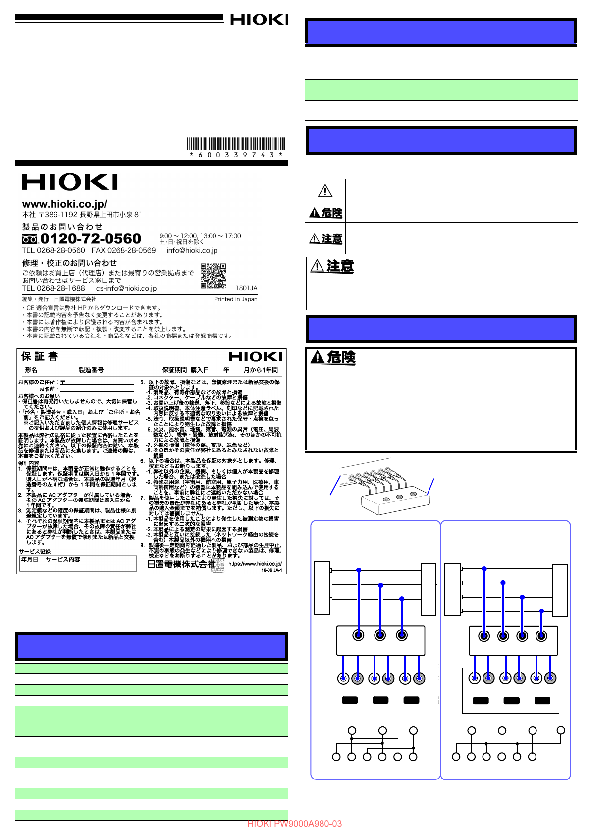
結線アダプタの出力端子 6 本
すべてを、接続する機器の電
圧入力端子に合わせて差し込
みます。
止まるまで確実に挿入してく
ださい。
例 :
A
B
C
U- U+ U- U+ U- U+
U INPUT
CH1 CH2 CH3 CH
L
O
A
D
青
A, B, C: Line
黄赤
S
O
U
R
C
E
電源側 負荷側
ABC
青黄赤黒黒黒
三相 3 線 (3P3W3M)
A
B
C
U INPUT
CH1 CH2 CH3 CH
赤
N
青黒黄
U- U+ U- U+ U- U+
S
O
U
R
C
E
L
O
A
D
A, B, C: Line
N: Neutral
電源側 負荷側
ABCN
青黄赤黒黒黒
三相 4 線 (3P4W)
U- U+ U- U+ U- U+
CH1 CH2 CH3
ABC
N
U- U+ U- U+ U- U+
CH1 CH2 CH3
AB
C
PW9001 結線アダプタ
PW9000 結線アダプタ
HIOKI PW9000A980-03
結線アダプタは、三相 3 線または三相 4 線の電源電圧ライン測定に使用する
PQ3198 電源品質アナライザ用のアダプタです。PW3390 パワーアナライ
ザにも使用できます。
PW9000
結線アダプタ
PW9001
結線アダプタ
三相 3 線用 (3P3W3M)
通常 6 本必要になる電圧コードを 3 本で結線できます。
三相 4 線用 (3P4W)
通常 6 本必要になる電圧コードを 4 本で結線できます。
ご使用の前に
安全についての注意および保守サービスについては、接続する機器の取扱説
明書をご覧ください。
注意や危険を示します。機器上にこの記号が表示されている場
合は、取扱説明書の該当箇所をご覧ください。
作業者が死亡または重傷に至る切迫した危険がある場合につい
て記述しています。
作業者が軽傷を負うおそれがある場合、または機器などに損害
や故障を引き起こすことが予想される場合について記述してい
ます。
感電事故を防ぐため、ケーブル内部から白または赤色部分(絶縁
層)が露出していないか確認してください。ケーブル内部の色が
露出している場合は、使用しないでください。
はじめに
このたびは、HIOKI PW9000, PW9001 結線アダプタ をご選定いただき、誠
にありがとうございます。この製品を十分にご活用いただき、末長くご使用
いただくためにも、取扱説明書はていねいに扱い、いつもお手元に置いてご
使用ください。
接続方法
・ 最大入力電圧を超える測定はしないでください。本器を破損し、
人身事故になります。
・ 対地間最大定格電圧は 1000 V (CAT Ⅲ ), 600 V (CAT Ⅳ ) で
す。大地に対してこの電圧を超える測定はしないでください。本
器を破損し、人身事故になります。
・ ただし、最大入力電圧や対地間最大定格電圧は、接続する機器
に依存します。
仕様
製品保証期間 1 年間
使用場所 屋内、高度 2000 m まで 汚染度2
使用温湿度範囲 -10C ~ 50C、80% rh 以下 ( 結露しないこと )
保存温湿度範囲 -20C ~ 50C、80% rh 以下 ( 結露しないこと )
最大入力電圧
対地間最大定格電圧
最大定格電流 1 A
耐電圧
適合規格 EN 61010、A タイプ
外形寸法 約 125W×80H×32D mm ( ケーブル長 約 152 mm)
質量 約 190 g
PW9000: 1000 V (A-B 間、B-C 間、C-A 間 )
PW9001: 1000 V (A-N 間、B-N 間、C-N 間 )
1740 V (A-B 間、B-C 間、C-A 間 )
1000 V、測定カテゴリⅢ ( 予想される過渡過電圧 8000V)
600 V、測定カテゴリⅣ ( 予想される過渡過電圧 8000V)
AC6.880 kVrms (50/60 Hz、感度電流 1 mA)
電圧入力端子 - ケース間
PW3390 への接続方法は、PW3390 の取扱説明書をご覧ください。
PW9000, PW9001
WIRING ADAPTER
Instruction Manual
EN
May 2020 Revised edition 3
PW9000A980-03 20-05H
PW9000
PQ3198
PW9000
Connect all 6 output pins on the
wiring adapter to the voltage input
terminals on the device to which it
is being connected. Insert plugs all
the way in.
Example:
A
B
C
U- U+ U- U+ U- U+
U INPUT
CH1 CH2 CH3 CH
L
O
A
D
Blue
A, B, C: Line
Yellow
Red
S
O
U
R
C
E
ABC
Blue
Yellow
Red
Black
Black
Black
Three-phase 3-wire (3P3W3M)
U- U+ U- U+ U- U+
U INPUT
CH1 CH2 CH3 CH
A
B
C
Red
N
Blue
Black
Yellow
S
O
U
R
C
E
L
O
A
D
A, B, C: Line
N: Neutral
ABCN
Blue
Yellow
Red
Black
Black
Black
Three-phase 4-wire (3P4W)
U- U+ U- U+ U- U+
CH1 CH2 CH3
ABC
N
U- U+ U- U+ U- U+
CH1 CH2 CH3
AB
C
PW9001 Wiring Adapter
PW9000 Wiring Adapter
HIOKI PW9000A980-03
Wiring Adapter
PW9001
Wiring Adapter
For three-phase 3-wire (3P3W3M)
Only three voltage cords need to be connected to the circuit, instead of six.
For three-phase 4-wire (3P4W)
Only four voltage cords need to be connected to the circuit, instead of six.
Before Use
For more information about safety precautions and maintenance service, refer
to the instruction manual for the device to which you plan to connect the wiring
adapter.
Indicates cautions and hazards. When the symbol is printed on
the instrument, refer to a corresponding topic in the Instruction
Manual.
Indicates an imminently hazardous situation that will result in
death of or serious injury to the operator.
Indicates a potentially hazardous situation that may result in
minor or moderate injury to the operator or damage to the device
or malfunction.
To prevent an electric shock accident, confirm that the white or red
portion (insulation layer) inside the cable is not exposed. If a color
inside the cable is exposed, do not use the cable.
Warranty
Warranty malfunctions occurring under conditions of normal use in conformity
with the Instruction Manual and Product Precautionary Markings will be
repaired free of charge. This warranty is valid for a period of one (1) year from
the date of purchase. Please contact the distributor from which you purchased the product for further information on warranty provisions.
Introduction
Thank you for purchasing the HIOKI Model PW9000/PW9001 Wiring Adapter.
To obtain maximum performance from the device, please read this manual
first, and keep it handy for future reference.
Specifications
Product warranty
period
Operating
environment
Storage temperature
and humidity
Operating temperature and humidity
Maximum input
voltage
Maximum rated voltage to earth
Maximum rated
current
Dielectric strength
Applicable standard EN 61010, A type
Dimensions
Mass Approx. 190 g (6.7 oz.)
The Wiring Adapter are specially designed to facilitate connections
to three-phase 3- and 4-wire systems using the PQ3198 Power Quality Analyzer. It can also be used with the PW3390 Power Analyzer.
Overview
1 year
Indoors, pollution degree 2, up to 2000 m ASL
-10°C to 50°C (14°F to 122°F), 80% RH or less
(non-condensing)
-20°C to 50°C (-4°F to 122°F), 80% RH or less
(non-condensing)
PW9000: 1000 V (between A and B, B and C, C and A)
PW9001: 1000 V (between A and N, B and N, C and N)
1000 V, Measurement category III
(anticipated transient overvoltage 8000 V)
600 V, Measurement category IV
(anticipated transient overvoltage 8000 V)
1 A
6.880 kVrmsAC (50/60Hz, current sensitivity 1 mA)
(Between voltage input terminals and case)
Approx. 125W×80H×32D mm (4.92”W×3.15”H×1.26”D)
(Cable length: Approx. 152 mm (5.98”))
1740 V (between A and B, B and C, C and A
Connecting a Wiring Adapter
• Do not exceed the maximum input voltage during measurement. Doing so may damage the adapter or cause injury.
• The maximum terminal-to-ground rated voltage is 1,000 V
(Cat III) or 600 V (Cat IV). Do not exceed these voltages relative to ground during measurement. Doing so may damage
the adapter or cause injury.
• The maximum input voltage and maximum terminal-toground rated voltage depend on the connected device.
For connection to the PW3390, see the PW3390 Instruction Manual.
 Loading...