

Hioki PW6001, PW6001-02, PW6001-03, PW6001-04, PW6001-05 Instruction Manual
...


Contents
Contents
Measurement Process .............................. 1
System Architecture .................................. 2
Example Measurement Setups................. 3
Introduction ................................................ 5
Verifying Package Contents ..................... 6
Options .........................................................7
Safety Information ..................................... 9
Operating Precautions .............................11
1 Overview 17
1.1 Product Overview ........................... 17
1.2 Features .......................................... 17
1.3 Part Names and Functions ............ 19
1.4 Basic Operation (Screen Display
and Layout) ..................................... 25
Screen Operation ........................................25
Common Screen Display ............................28
Measurement Screen Display .....................29
Screen Layouts ...........................................30
2 Preparing for
Measurement 33
2.1 After Purchase ................................ 33
Wrapping voltage cords in spiral tubes .......33
2.2 Inspecting the Instrument
before Use ....................................... 34
2.3 Connecting the Power Cord .......... 35
2.4 Connecting the Voltage Cords ...... 35
2.5 Connecting the Current Sensors .. 36
Connecting a current sensor to the
Probe1 terminal ..........................................37
Connecting a current sensor to the
Probe2 terminal ..........................................38
If the measurement range exceeds
(using a VT and CT) ...................................39
2.6 Turning the Instrument On/Off ...... 40
2.7 Setting the Connection Mode
and Current Sensors ...................... 41
2.8 Connecting the Instrument to
the Measurement Lines (Zero-
adjustment) ..................................... 43
Zero-adjustment and degaussing (DMAG) .43
Connecting the voltage cords to the
measurement lines .....................................44
Connecting the current sensor to the
measurement lines .....................................44
Using the quick conguration function ........45
2.9 Verifying Proper Connections
(Connection Check) ....................... 47
3 Viewing Measured
Values 49
3.1 Displaying Measured Values ......... 49
Selecting display parameters ......................49
3.2 Viewing Power Measured Values
and Changing Measurement
Conditions ...................................... 52
Displaying power measured values ............52
Displaying voltage and current ...................53
Setting the ranges .......................................53
Conguring zero-suppression .....................56
Setting the data update rate .......................57
Setting the synchronization source .............58
Setting the low-pass lter (LPF) ..................59
Conguring frequency measurement ..........60
Setting the frequency source ......................60
Setting the measurement upper limit
frequency and the lower limit frequency .....61
Setting the rectier ......................................62
Conguring scaling (when using a VT
[PT] or CT) ..................................................62
3.3 Viewing Integration Values ............ 63
Displaying integration values ......................63
Setting the integration mode .......................66
Using manual integration ............................67
Performing integration while using the
time control function ....................................68
3.4 Viewing Harmonic Measured
Values .............................................. 69
Displaying harmonics ..................................69
Setting the harmonic measurement mode ..72
Setting the THD calculation method ...........73
THD calculation order .................................73
Setting the grouping method .......................74
3.5 Viewing Measured Values for
Power Factor and Loss .................. 75
Displaying efciency and loss .....................75
Setting the calculation formulas for
efciency and loss ......................................76
Example measurements .............................77
3.6 Viewing Motor Measured
Values (Motor Analysis and D/
A-equipped Models) ....................... 80
Displaying motor measured values .............80
Performing zero-adjustment of motor input 81
Setting motor input ......................................82
Measuring a motor’s electrical angle ..........89
Detecting the motor’s direction of rotation ..91
1
2
3
4
5
6
7
8
9
10
Appx. Ind.
PW6001A961-04
i

Contents
4 Viewing Waveforms 93
4.1 Displaying Waveforms ................... 93
Displaying waveforms on the WAVE
screen .........................................................93
Displaying waveforms and measured
values on the WAVE+VALUE screen ..........94
Initializing the display position ....................94
4.2 Changing the Waveform Display
and Conguring Recording ........... 96
Vertical axis zoom factor and display
position settings ..........................................96
Time axis setting .........................................97
Detailed display settings .............................99
Vertical axis scale display ...........................99
Trigger settings .........................................100
4.3 Recording Waveforms ................. 102
Recording a waveform continuously .........102
Recording a waveform once .....................102
Activating the trigger manually ..................102
4.4 Analyzing Displayed Waveforms 103
Viewing displayed waveform values
(Cursor measurement) ..............................103
Enlarging waveforms (zoom function) ......104
4.5 Viewing FFT Analysis Results .... 105
Displaying waveforms and FFT analysis
results .......................................................105
Changing the window size and position ....106
Displaying FFT analysis results as values 108
Turning the display of FFT analysis
results on and off ......................................108
Setting the lower limit frequency for the
FFT peak value display .............................109
Setting the window function ...................... 110
Changing the scale of the vertical axis
on the FFT analysis results display .......... 111
5 Using the Instrument’s
Functionality 113
5.1 Time Control Function ..................113
Interval time control .................................. 11 3
Timer time control .....................................113
Actual time control .................................... 113
5.2 Averaging Function .......................115
Simple average (ADD) .............................. 11 5
Exponential average (EXP) ...................... 11 5
5.3 Hold and Peak Hold Functions ....117
Hold function ............................................. 11 7
Peak hold function .................................... 119
5.4 Delta Conversion Function ......... 122
-Y conversion ..........................................122
∆
Y-∆ conversion ..........................................123
5.5 Selecting the Power Calculation
Formula ......................................... 124
5.6 Current Sensor Phase Shift
Function ........................................ 125
5.7 User-dened Calculations (UDF) 127
5.8 Simple Graph Function ................ 129
D/A monitor graph .....................................129
Detailed display settings ...........................130
Vertical axis scale display .........................130
X-Y plot function .......................................131
Vertical axis/horizontal axis scale
settings, integration full-scale setting ........133
6 Changing System
Settings 135
Checking and changing settings ...............135
Correcting the touch panel ........................136
6.1 Initializing the Instrument ............ 136
System reset .............................................136
Boot key reset ...........................................136
6.2 Default Settings ............................ 137
7 Saving Data and
Manipulating Files 139
7.1 Inserting and Removing USB
Flash Drives .................................. 139
7.2 File Operations Screen ................ 141
7.3 Saving Measurement Data .......... 142
Setting which measurement parameters
to save ......................................................142
Manually saving measurement data .........144
Automatically saving measurement data ..145
Automatic save operation using time
control .......................................................147
7.4 Saving Waveform Data ................ 148
7.5 Saving FFT Data ........................... 150
7.6 Saving Screenshots ..................... 152
7.7 Saving Settings Data ................... 153
7.8 Loading Screenshots ................... 154
7.9 Loading Settings Data ................. 154
7.10 File and Folder Operations .......... 155
Creating a folder .......................................155
Deleting les and folders ..........................155
Changing the name of a le or folder ........156
Copying les .............................................156
Formatting a USB ash drive ....................156
7.11 Measured Value Data Format ...... 157
Header structure .......................................157
Status data ................................................160
Measured value data format .....................162
7.12 Waveform Binary Data Format .... 163
ii

Contents
Data format ...............................................163
8 Connecting External
Devices 169
8.1 Synchronization Interface
(Two-instrument Synchronized
Measurement) ............................... 169
Connecting 2 instruments with the
L6000 Optical Connection Cable ..............170
8.2 Using D/A Output (Motor
Analysis and D/ A-equipped
Models Only) (Analog and
Waveform Output) ........................ 173
Connecting an application-specic
device to the instrument ............................173
Selecting output parameters .....................175
Output rates ..............................................178
Examples of D/A output ............................180
8.3 Using Motor Analysis (Motor
Analysis and D/ A-equipped
Models Only) ................................. 182
Connecting a torque meter and
tachometer ................................................182
8.4 Controlling Integration with
External Signals ........................... 185
8.5 Connecting an LR8410 Link-
compatible Logger ....................... 188
9 Connecting the
Instrument to a
Computer 189
9.1 Using the LAN Interface .............. 190
Conguring LAN settings and building a
network environment ................................190
Connecting the LAN cable ........................192
Controlling the instrument remotely with
an Internet browser ...................................193
9.2 Performing Instrument File
Operations from a Computer
(Using FTP) ................................... 195
Using FTP to connect to the instrument ...196
Performing le operations with FTP ..........197
9.3 Using GP-IB .................................. 198
Connecting the GP-IB cable .....................199
Setting the GP-IB address ........................199
9.4 Using RS-232C ............................. 200
Conguring the D-sub 9-pin connector .....201
Connecting the RS-232C cable ................202
9.5 Canceling the Remote State
(Reverting to the Local State) ..... 203
10 Specications 205
10.1 General Specications ................ 205
10.2 Basic Specications .................... 206
10.3 Functional Specications ............ 221
10.4 Measurement Parameter
Detailed Specications ................ 231
10.5 Calculation Formula
Specications ............................... 239
11 Maintenance and
Service 251
11.1 Repairs, Inspections, and
Cleaning ........................................ 251
11.2 Disposing of the Instrument ....... 253
Removing the lithium battery ....................253
11.3 Replacement Parts and Their
Service Lives ................................ 254
Replacing the fuse ....................................254
12 Troubleshooting 255
12.1 Frequently Asked Questions ....... 255
12.2 Error Displays ............................... 257
Startup errors and operating errors ..........257
Control errors ............................................257
USB ash drive and le operation errors ..259
Appendix Appx.1
Appx. 1 Rack-mounting the
Instrument ........................ Appx.1
Rack-mounting hardware .....................Appx.1
Installation instructions ........................Appx.4
Appx. 2 Outline Drawings ............. Appx.6
Index Ind.1
11
12
3
4
5
6
7
8
9
10
Appx.
Appx. Ind.
iii

iv
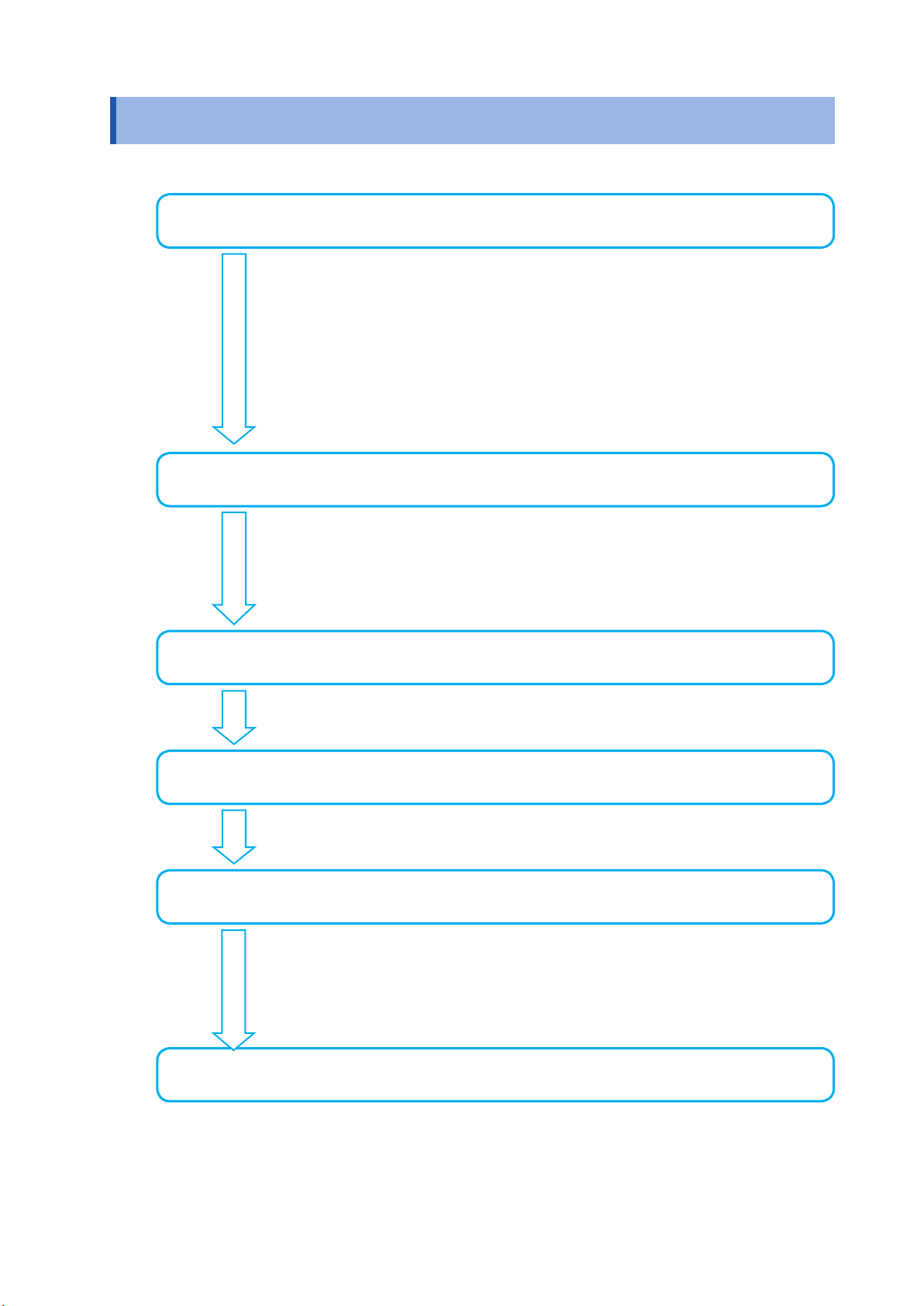
Measurement Process
Be sure to read “Operating Precautions” (p. 11) before use.
Setting up the instrument
• “Instrument placement” (p. 12)
• “2.1 After Purchase” (p. 33)
• “2.2 Inspecting the Instrument before Use” (p. 34)
• Be sure to inspect the instrument before connecting it or turning it on.
• “2.3 Connecting the Power Cord” (p. 35)
• “2.6 Turning the Instrument On/Off” (p. 40)
To ensure accurate measurement, allow a warm-up period of at least
30 minutes to elapse after turning on the instrument before performing
zero-adjustment.
Connecting the instrument
Measurement Process
• “2.7 Setting the Connection Mode and Current Sensors” (p. 41)
• Be sure to perform zero-adjustment before connecting the instrument.
• “2.8 Connecting the Instrument to the Measurement Lines (Zero-
adjustment)” (p. 43)
• “2.9 Verifying Proper Connections (Connection Check)” (p. 47)
Setting the measurement conditions
• “3 Viewing Measured Values”(p. 49)
• “4 Viewing Waveforms”(p. 93)
Viewing measured values
• “3 Viewing Measured Values”(p. 49)
• “4 Viewing Waveforms”(p. 93)
Saving data
• “Manually saving measurement data” (p. 144)
• Saving data with actual time control (p. 147)
Saving data with timer control (p. 147)
•
Saving data with interval control (p. 147)
•
• USB ash drive and the instrument’s internal memory (p. 139)
Analyzing data
• “8 Connecting External Devices”(p. 169)
• “9 Connecting the Instrument to a Computer”(p. 189)
1
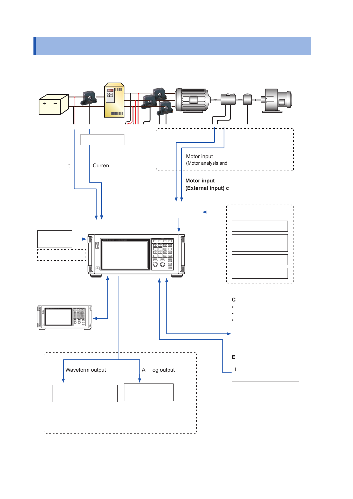
System Architecture
System Architecture
Inverter
Battery
sensor
EncoderTorque
Current sensor
Voltage input Current input
Input channels
USB ash
drive
Internal memory
Motor
Motor input
(Motor analysis and D/A-equipped models only)
Motor input
(External input) channels
Some combination
of inputs
Load
Encoder signalTorque sensor signal
External input
Pyranometer output
Thermometer analog
output
Pulse signal
Waveform trigger
Two-instrument
synchronization
Waveform output Analog output
Oscilloscope, memory
recorder, etc.
Communications interfaces
• LAN
• GP-IB
• RS-232C
Computer, controller, etc.
External control
Integration control
Start/stop/reset
Logger,
comparator, etc.
D/A output
Motor input
(Motor analysis and D/A-equipped models only)
2

Example Measurement Setups
Example Measurement Setups
Conversion efciency measurement of inverters with built-in SiC
3-phase
power
supply
Measuring the efciency of PV power conditioners
DC measurement
Converter
Power conditioner
Solar panel
Inverter
AC measurement
Motor
Power system
Load
EV/HEV motor analysis
Battery
Inverter Motor
Torque
sensor
Pulse
encoder
Load
3

Example Measurement Setups
4
Introduction
Thank you for purchasing the Hioki PW6001 Power Analyzer. To obtain maximum performance
from the product, please read the instruction manual rst, and keep it handy for future reference.
• One or more clamp-on sensors, AC/DC current sensors, or other sensors are required in order
to provide current input to the instrument. (These devices are referred to collectively as “current
sensor(s)” in this manual.) For more information, see the instruction manual for the current
sensor(s) you are using.
• One or more voltage cords (voltage measurement option) or other similar cords are required
in order to provide voltage input to the instrument. The instrument’s voltage input terminals
use standard φ 4 mm CAT II (1000 V) or CAT III (600 V) compatible safety banana connectors.
Provide voltage cords as appropriate for your application.
Trademarks
• Microsoft and Windows are either registered trademarks or trademarks of Microsoft Corporation
in the United States and other countries.
• Adobe and Adobe Reader are trademarks of Adobe Systems Incorporated.
• Bluetooth® is a registered trademark of Bluetooth SIG, Inc.(USA). The trademark is used by
HIOKI E.E. CORPORATION under license.
• ParaniTM is a registered trademark of Sena Technologies, Inc.
Introduction
Product model numbers
Right side
Product model number
PW6001-01 1 n/a
PW6001-02 2 n/a
PW6001-03 3 n/a
PW6001-04 4 n/a
PW6001-05 5 n/a
PW6001-06 6 n/a
PW6001-11 1 Motor analysis and D/A output
Number of input
channels
Product model number
Additional functionality
PW6001-12 2 Motor analysis and D/A output
PW6001-13 3 Motor analysis and D/A output
PW6001-14 4 Motor analysis and D/A output
PW6001-15 5 Motor analysis and D/A output
PW6001-16 6 Motor analysis and D/A output
In this manual, models equipped with motor analysis and D/A output functionality are referred to as “motor
analysis and D/A-equipped models.”
5
Verifying Package Contents
Verifying Package Contents
Once you have received the instrument, verify that it has not suffered any damage during shipment
before using it. Pay particular attention to accessories, panel switches, and terminals. If you discover any
damage or nd that the instrument does not operate as stipulated in its specications, please contact your
authorized Hioki distributor or reseller. When transporting the instrument, use the original packaging.
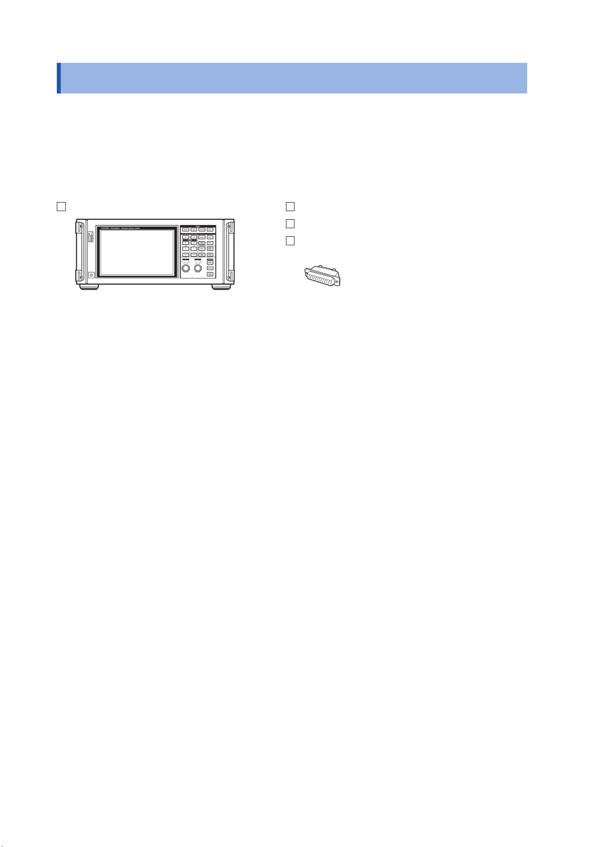
Verify that the packaging includes all contents.
PW6001 Power Analyzer Instruction manual
Power cord
D-sub 25-pin connector
(Motor analysis and D/A-equipped models only)
6
Options
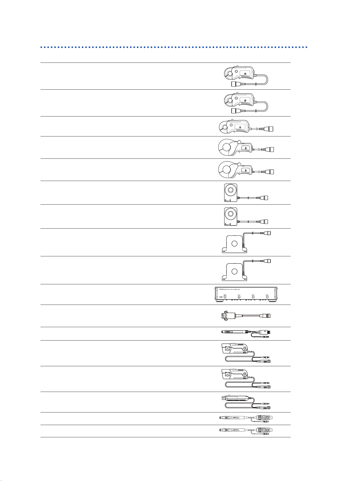
Current measurement options
CT6841 AC/DC Current Probe (20 A)
CT6843 AC/DC Current Probe (200 A)
CT6844 AC/DC Current Probe (500 A)
CT6845 AC/DC Current Probe (500 A)
CT6846 AC/DC Current Probe (1000 A)
Verifying Package Contents
CT6862 AC/DC Current Sensor (50 A)
Cord length: 3m
CT6863 AC/DC Current Sensor (200 A)
Cord length: 3 m
9709 AC/DC Current Sensor (500 A)
Cord length: 3 m
CT6865 AC/DC Current Sensor (1000 A)
Cord length: 3 m
PW9100 AC/DC Current Box (50 A)
CT9900 Conversion Cable
(PL23 receptacle/ME15W plug)
3273-50 Clamp On Probe (30 A)
3274 Clamp On Probe (150 A)
3275 Clamp On Probe (500 A)
3276 Clamp On Probe (30 A)
CT6700 Current Probe (5 A)
CT6701 Current Probe (5 A)
7
Verifying Package Contents
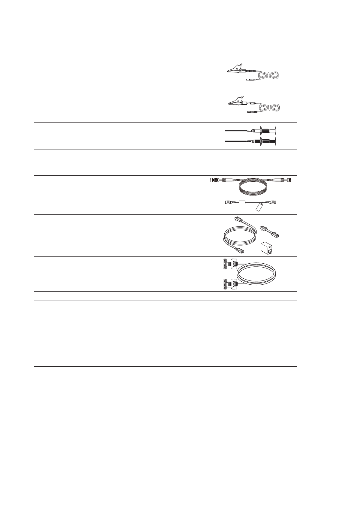
Voltage measurement options
L9438-50 Voltage Cord
(Banana connector/banana connector; red and
black × 1 ea.; cord length: approx. 3 m)
L1000 Voltage Cord (banana connector/banana
connector; red, yellow, blue, and gray × 1 ea.;
black × 4; cord length: approx. 3 m with alligator
clips)
9243 Grabber Clip (red and black × 1 ea.)
Connection options
L6000 Optical Connection Cable (10 m)
L9217
9642
9637 RS-232C Cable (9-pin/9-pin; cross; 1.8 m)
9151-02 GP-IB Connector Cable (2 m)
9444
Connection Cord (isolated BNC; 1.7 m; for motor
input)
LAN Cable
(CAT 5e with cross conversion connector; 5 m)
Connection Cable
(For external control use; 9-pin/9-pin; straight;
1.5 m)
Other options
Specialorder
Specialorder
Rack mount hardware (for EIA or JIS)
Carrying case
(Rigid trunk type; with casters)
8
Safety Information
Safety Information
The PW6001 has been designed and tested in accordance with the IEC 61010 safety standard and
shipped in a safe state. However, failure to adhere to the precautionary information and follow the
instructions provided in this instruction manual may render safety-related functionality provided by
the instrument inoperable.
Before using the instrument, be sure to carefully review the following important safety information.
DANGER
Improper use of the instrument may result in bodily injury or equipment damage.
Read this instruction manual carefully and ensure that you understand its contents
before operating the instrument.
WARNING
Electricity poses a number of hazards, including electric shock, overheating, re,
and arc discharge (caused by a short). Individuals using an electrical measuring
instrument for the rst time should be supervised by a technician who has experience
in electrical measurement.
Safety-related notations
This manual classies safety information on the basis of the severity of the associated risk and
hazard level using the following categories.
DANGER
WARNING
CAUTION
IMPORTANT
*
Indicates an imminent hazard that could lead to serious injury or death.
Indicates a hazard that could lead to serious injury or death.
Indicates a hazard that could lead to minor injury or that could be expected to
result in equipment or other damage.
Indicates information or content that is especially important to keep in mind when
operating the instrument or performing maintenance work.
Indicates a high-voltage hazard.
Warns that failure to verify safety or improper use of the instrument could lead to
electric shock, burns, or death.
Indicates an action that you must refrain from performing.
Indicates an action that you must perform.
Indicates that there is additional information below.
p.
[ ]
ON
Unless otherwise noted, the term “Windows” is used in this manual to refer to Windows XP, Windows Vista,
and Windows 7.
Indicates a reference page number.
Key names are enclosed in parentheses.
Text shown on the instrument’s screen is formatted in bold.
9
Safety Information
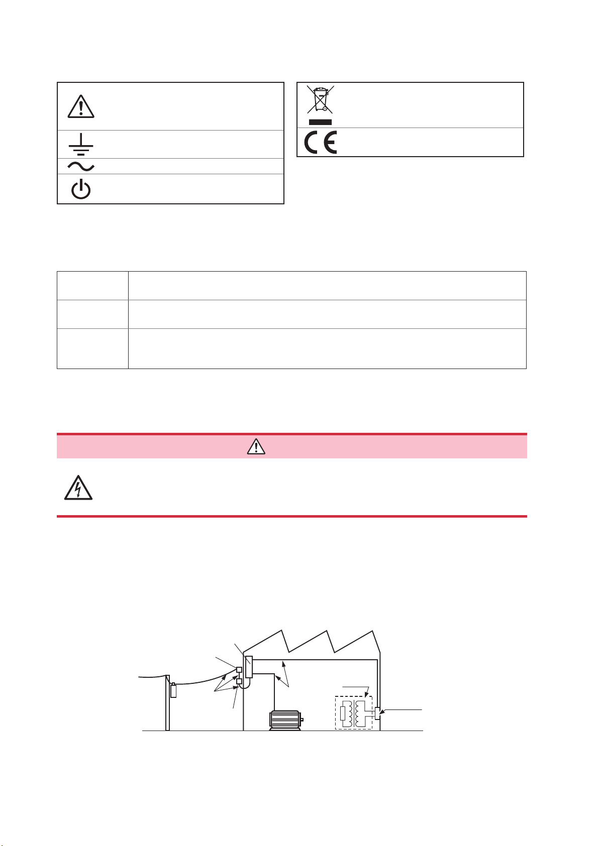
Symbols displayed on the instrument
Indicates the need for caution or a hazard.
When this symbol is displayed on the
instrument, refer to the corresponding
section of the instruction manual.
Indicates the ground terminal.
Indicates AC (Alternating Current)
Indicates the power supply’s “on” and “off”
positions.
Symbols related to standards
Indicates the Waste Electrical and
Electronic Equipment Directive (WEEE
Directive) in EU member states.
Indicates that the product conforms to
regulations set out by the EC Directive.
Accuracy
We dene measurement tolerances in terms of f.s. (full scale), rdg. (reading) and dgt. (digit) values, with
the following meanings:
f.s.
rdg.
dgt.
(Maximum display value)
The maximum displayable value. This is usually the name of the currently selected range.
(Reading or displayed value)
The value currently being measured and indicated on the measuring instrument.
(Resolution)
The smallest displayable unit on a digital measuring instrument, i.e., the input value that causes
the digital display to show a “1” as the least-signicant digit.
Measurement categories
To ensure safe operation of measurement instruments, IEC 61010 establishes safety standards
for various electrical environments, categorized as CAT II to CAT IV, and called measurement categories.
DANGER
• Never use a measuring instrument whose measurement category is lower than the
location in which it will be used. Doing so may result in a serious accident.
• Never use a measuring instrument with no category labeling in a CAT II to CAT IV
measurement category. Doing so may result in a serious accident.
The PW6001 conforms to the safety requirements for CAT II (1000 V) and CAT III (600 V) measuring instruments.
CAT II: When directly measuring the electrical outlet receptacles of the primary electrical circuits in equipment
connected to an AC electrical outlet by a power cord (portable tools, household appliances, etc.)
CAT III: When measuring the primary electrical circuits of heavy equipment (xed installations) connected directly to
the distribution panel, and feeders from the distribution panel to outlets
CAT IV: When measuring the circuit from the service drop to the service entrance, and to the power meter and
primary overcurrent protection device (distribution panel)
Distribution panel
Service entrance
Service drop
CAT IV
Power meter
Internal wiring
CAT III
CAT II
T
Outlet
10
Fixed installation
Operating Precautions
Operating Precautions
Please observe the following precautions to ensure that you can use the instrument safely and fully utilize
its functionality.
Checking the instrument before use
Before using the instrument, check the instrument for any damage that may have been sustained
while in storage or transit, inspect it, and verify that it is operating properly. If you discover any
malfunction or damage, contact your authorized Hioki distributor or reseller.
DANGER
Damage to voltage cords or the instrument may result in electric shock. Check
voltage cords for worm insulation and exposed metal before use. If you nd
damage, replace the cords with those specied by our company. Failure to do so
may result in electric shock.
WARNING
To prevent electric shock, verify that the white or red portion of the cable
(insulation layers) are not exposed. If any color is visible from the inside of the
cable, do not use the instrument.
Installation
Installing the instrument in inappropriate locations may cause a malfunction of instrument or may
give rise to an accident. Avoid the following locations.
WARNING
• Exposed to direct sunlight or high temperature
• Exposed to corrosive or combustible gases
• Exposed to water, oil, chemicals, or solvents
• Exposed to high humidity or condensation
• Exposed to a strong electromagnetic eld or electrostatic charge
• Exposed to high quantities of dust particles
• Near induction heating systems (such as high-frequency induction heating
systems and IH cooking equipment)
• Susceptible to vibration
CAUTION
• Do not place the instrument on an unstable bench or inclined surface. Doing so may
cause the instrument to fall off the surface or to fall over, resulting in bodily injury or
equipment damage.
• Do not use an uninterruptible power supply (UPS) or a DC-AC inverter that produces
rectangular waves or pseudo-sine-wave output to power the instrument. Doing so
may damage the instrument.
11
Operating Precautions
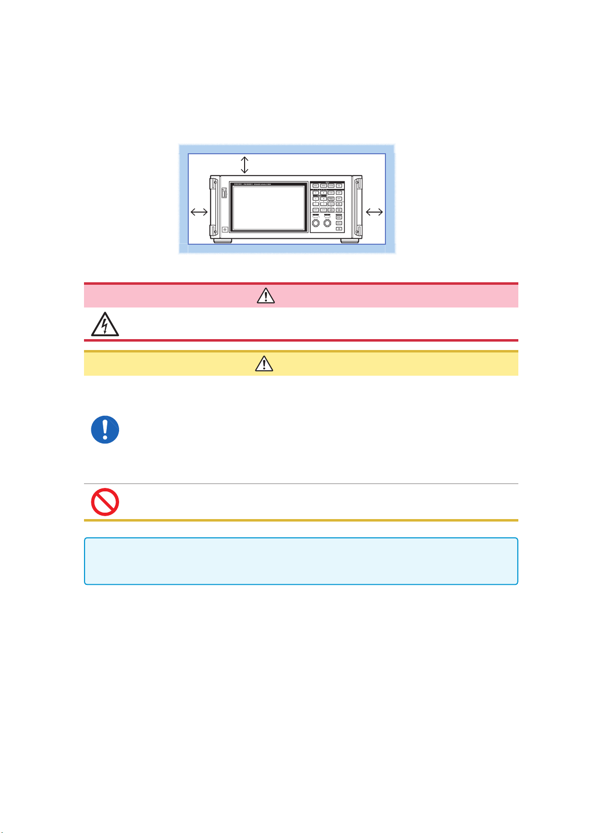
Instrument placement
• Place the instrument right-side up.
• Do not block the instrument’s air vents.
• Leave at least 20 mm between the instrument’s air vents and surrounding surfaces.
See “1.3 Part Names and Functions” (p. 19).
Handling of the instrument
At least 20 mm on all sides
DANGER
To prevent electric shock, never remove the instrument’s enclosure. There are
high-voltage and high-temperature parts inside the instrument.
CAUTION
• To prevent damage to the instrument, avoid exposing it to vibration or mechanical
shock when transporting or otherwise handling it. Exercise particular care not to drop
the instrument.
• If the instrument malfunctions or displays an error during use, consult
“12 Troubleshooting” (p. 255) and then contact your authorized Hioki distributor or
reseller.
• Carry the instrument using its handle after disconnecting all cords and removing the
USB ash drive.
• Do not press down on the touch panel with excessive force or use hard or sharp
objects to press down on the touch panel. Doing so may result in equipment damage.
This instrument may cause interference if used in residential areas. Such use must be avoided
unless the user takes special measures to reduce electromagnetic emissions to prevent
interference to the reception of radio and television broadcasts.
12
Cord and current sensor handling
• Always connect voltage cords and current sensors to the secondary side of a
circuit breaker. The secondary side will be protected by the breaker in the event
of a short. Do not measure the primary side of a circuit breaker as it will carry a
larger current, increasing the amount of damage in the event of a short-circuit.
• When using the instrument, always use the designated power cord. Use of a
power cord other than the designated cord may result in re.
• Connect current sensors and voltage cords to the instrument before connecting
them to a live measurement line. Observe the following precautions to prevent
short-circuits and electric shock:
• Do not place the metal part of the tips of voltage cord clips across two
measurement lines at the same time. Never touch the metal part of the tips of
voltage cord clips.
• When a current sensor is in the open position, do not place the metal part
of its clamp tip across two measurement lines at the same time or use the
sensor on a bare conductor.
• Do not connect voltage cords unnecessarily.
Operating Precautions
DANGER
• To prevent short-circuit or bodily injury, use current sensors with circuits
whose voltage is less than or equal to the sensor’s maximum rated input-toground voltage. Do not use current sensors with bare conductors. (For more
information about a current sensor’s maximum rated input-to-ground voltage,
refer to its instruction manual.)
WARNING
• When using an AC/DC Current Sensor such as the CT6862, it is necessary to
cut the measurement line in order to route it through the sensor. To prevent
an electric shock or short-circuit, turn off all equipment before connecting the
sensor.
• To prevent an electric shock or short-circuit, use the designated voltage cords
to connect the measurement lines to the instrument’s voltage input terminals.
CAUTION
• To ensure safety, use only voltage cords designated by our company.
• To prevent a break in instrument wiring, grip the plug (not the cord) when unplugging
the power cord from an outlet or disconnecting it from the instrument.
• Exercise caution as conductors being measured may become hot.
• To avoid damaging cord insulation, do not step on cords or allow them to be pinched
between other objects.
• If a voltage cord melts, its metal conductor may be exposed. Do not use a cord whose
metal conductor is exposed. Doing so may result in electric shock, burns, or other
injury.
• Do not drop current sensors or subject them to mechanical shock. Doing so may
damage the core joint and adversely impact measurement. When disconnecting a
connector, always release the lock and then grip the connector to pull it out. Pulling
on connectors with excessive force before releasing the lock or pulling on cables will
cause damage to connectors. (p. 36)
• Do not connect or disconnect connectors while the instrument is on or while a sensor
is clamped to the conductor being measured. Doing so may damage the instrument or
current sensor.
13
Operating Precautions
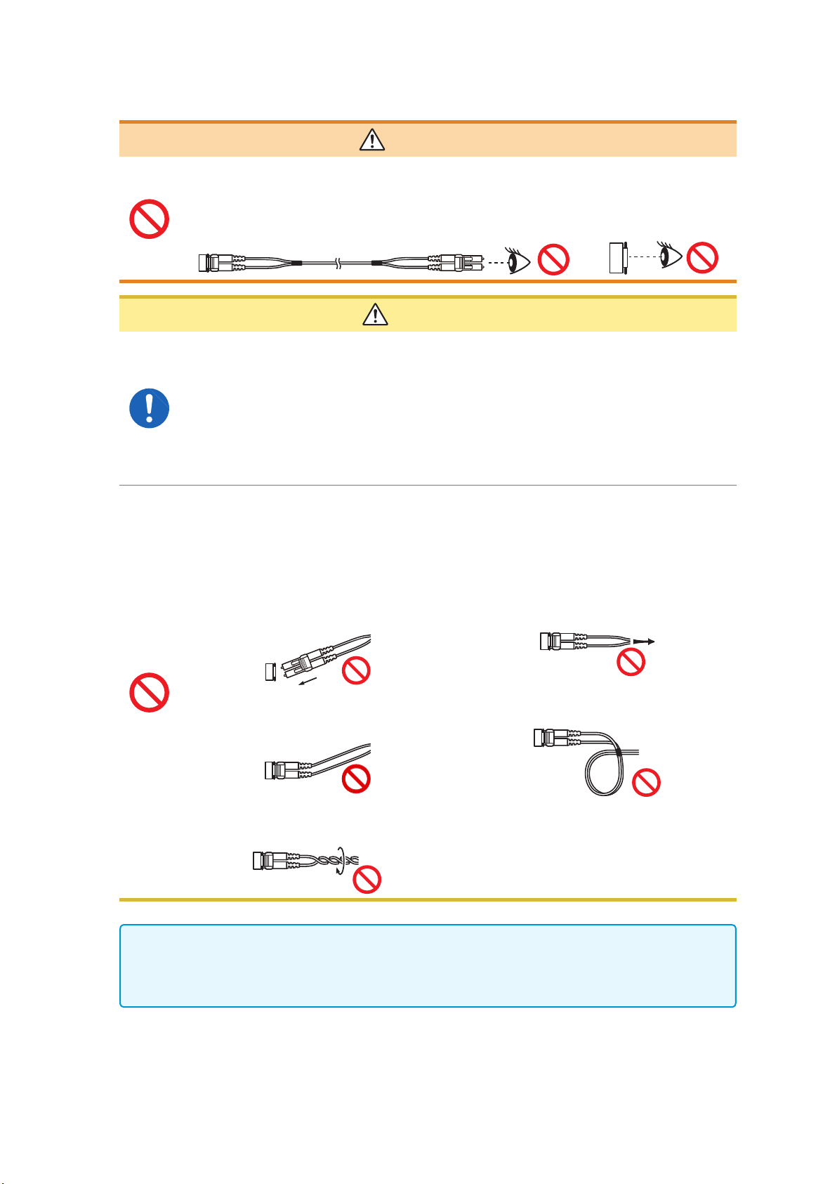
Handling of the L6000 Optical Connection Cable
WARNING
When connecting an L6000 Optical Connection Cable that is already connected
to an operating optical output to the instrument, never look directly at the tip of
the cable or observe it with a device such as a magnifying glass. Doing so may
adversely affect your eyes or damage your vision.
CAUTION
• When connecting an L6000 Optical Connection Cable to the instrument, exercise care
to ensure that there is no dirt or dust in the optical connector. In particular, exercise
caution concerning the end face (ferrule). Accurate measurement may be impossible
if the cable is connected while there is dirt or other foreign matter on the face, or if the
face is scratched or otherwise damaged.
• The instrument’s two-instrument synchronization connector and the L6000 Optical
Connection Cable’s optical connector are precisely machined parts. When not in use,
always attach the included dust cap to each.
• When cleaning the center of an optical connector, do not apply excessive force to the
cleaning cloth. Doing so may damage the connector, preventing it from performing to
specications.
• To prevent damage to the L6000 Optical Connection Cable, observe the following
precautions:
• Do not insert the optical connector at an
angle.
• Do not bend the cable at the neck of the
optical connector.
• Do not bend or twist the cable. • Do not touch the end face (ferrule).
• Do not pull on the cable with excessive
force.
• Do not allow the cable to become kinked.
14
• Clean the optical connector end face (ferrule) of the L6000 Optical Connection Cable each time
it is connected.
• To clean the L6000 Optical Connection Cable’s optical connectors, use the 9738 Optical
Connector Cleaner.
Before connecting the instrument
• Do not measure voltages that exceed the rating indicated on the instrument
labeling or the measurement range listed in the specications. Doing so may
result in damage to the instrument or bodily injury.
• The maximum rated input-to-ground voltages for the instrument’s voltage
inputs are as follows:
CAT II: 1000 V DC, 1000 V AC rms
CAT III: 600 V DC, 600 V AC rms
Do not measure a voltage in excess of these limits. Doing so may result in
damage to the instrument or bodily injury.
• The Probe1 and Probe2 terminals are not isolated. These input terminals are
provided for use with optional current sensors only. Connections of input other
than output from an optional current sensor may damage the instrument or
result in bodily injury.
• To avoid electric shock and instrument damage, do not input a voltage in
excess of the maximum input voltage to the instrument’s external input
terminals.
Operating Precautions
DANGER
• Before turning on the instrument, verify that the supply voltage being used is
the same as that noted on the instrument’s power inlet. Use of a voltage outside
the specied supply voltage range may result in damage to the instrument or
an electrical accident.
• To avoid an electric shock or short-circuit, verify that all connections have been
made securely. Loose terminals may result in increased contact resistance,
causing overheating, equipment burnout, or re.
• Connect voltage cords to input terminals securely. Loose terminals may result
in increased contact resistance, causing overheating, equipment burnout, or
re.
To ensure safety, always disconnect the power cord from the instrument and isolate the
instrument from the power supply completely when not in use.
Measurement precautions
WARNING
CAUTION
WARNING
If you notice smoke, an unusual sound, an unusual odor, or other anomaly,
halt measurement immediately, disconnect measurement lines, turn off the
instrument, unplug the power cord from the outlet, and disconnect the instrument
from the measurement target. Then contact your authorized Hioki distributor or
reseller. Continued use may result in re or electric shock.
15

Operating Precautions
Precautions when transporting the instrument
CAUTION
• To transport the instrument safely, use the packing box and cushioning material in
which the product was shipped from Hioki. However, do not use the packing box if it is
torn or deformed, and do not use the cushioning material if it has been crushed. If you
are unable to use the packing box and cushioning materials in which the product was
shipped from Hioki, consult your authorized Hioki distributor or reseller.
• Be sure to disconnect any voltage cords and current sensors as well as power cords
from the instrument before packing it. When transporting, avoid dropping or other
excessive impact.
• Pack the instrument so that it will not be damaged during shipment and note the
nature of the malfunction. Damage occurred during transportation is not covered by
warranty.
16

Product Overview
1
Overview
1.1 Product Overview
The PW6001 series of power analyzers comprises models with simultaneous measurement capabilities
for targets ranging from one 1-phase/2-wire circuit to two 3-phase/4-wire circuits, enabling them to
accommodate a variety of measurement lines. Variants offer from one to six channels.
For use in the development and evaluation of increasingly efcient inverter motors
• The PW6001 can perform high-precision, high-stability, wideband inverter power measurement that is highly
reproducible.
• The instrument can perform electrical angle measurement, which is a necessary part of motor analysis.
• When connected to a high-precision torque meter and encoder, the instrument can measure motor efciency.
For use in the development and evaluation of alternative energy technologies,
including solar power, wind power, and fuel cells
• The PW6001 can simultaneously measure AC power and DC power at a high level of precision and calculate
efciency.
• The instrument can measure power drawn from the grid, power sold to the grid, and power by consumption/
generation by means of DC mode and RMS mode current and power integration.
1
Overview
For use in the measurement of high-frequency power in wireless power feeds
and DC/DC converters
• The PW6001 can measure power at frequencies of up to 1 MHz.
• The instrument can measure and analyze harmonic distortion of switching waveforms at frequencies of up to
300 kHz.
1.2 Features
Simultaneous measurement of multiple circuits incorporating various types
of power lines (p. 41)
• For 3-phase/3-wire circuits, users can select a Hioki model 3193-compatible 3V3A connection or a Hioki
model 3390-compatible 3P3W3M connection in addition to the two-wattmeter method. The 3P3W3M
connection is particularly well suited to measuring power with inverter motors that have high-frequency leak current.
High accuracy and highly stable circuitry for high measurement reproducibility (p. 75)
The instrument delivers best-in-class basic accuracy and DC accuracy for active power and therefore provides
support for DC/AC conversion efciency with high-accuracy measurement performance.
High-bandwidth, high-speed opto-isolated sampling
• The PW6001 can measure increasingly high-speed switching waveforms accurately thanks to wideband
voltage and current input circuits (DC, 0.1 Hz to 2 MHz) and 5 MS/s, 18-bit high-speed, high-resolution
sampling capability.
• Thanks to its use of voltage inputs that use new optical devices to implement isolation with a high dielectric
strength, the instrument delivers a CMRR of 80 dB (at 100 kHz), enabling it to aggressively reject highfrequency common-mode noise when measuring inverters.
Support for a variety of current sensors (p. 36)
• In addition to conventional power measurement sensors, the PW6001 supports wideband current probes
designed for use with megahertz-order frequencies.
• The instrument ships standard with a power supply for 3270 series clamp-on probes.
17

Features
New functionality to take full advantage of current sensor performance (p. 125)
The instrument’s phase compensation calculations can correct current sensor’s high-frequency phase
characteristics.
Complete six-channel + dual mode harmonic analysis function (p. 69)
The PW6001 supports simultaneous harmonic analysis for all channels. By performing simultaneous harmonic
analysis for multiple circuits with different frequencies, the instrument can perform simultaneous harmonic
analysis for both the primary and secondary sides of an inverter.
Waveform observation functionality on par with that of an oscilloscope (p. 93)
The PW6001 can record waveforms of up to 100 sec. in duration (10 kS/s sampling) or 10 sec. in duration (at
100 kS/S sampling) thanks to its large waveform storage memory (1 Mword × 6 voltage/current channels).
Standard USB ash drive support and large internal memory (p. 139)
• Thanks to its large, 64 MB internal memory capacity, the PW6001 can continuously record data for numerous
parameters even when using a high-speed interval.
• Data can be saved directly on a USB ash drive, screens can be copied to a USB ash drive, and data can
be copied from the internal memory to a USB ash drive.
Easy-to-understand touch panel and key operation (p. 19)
• The PW6001 can be controlled using either dedicated hardware keys or an easy-to-understand touch panel.
• Comments can be entered on the touch panel when saving screen copies and measurement data.
Robust motor analysis functionality (option) (p. 182)
• When fed output from a torque meter and tachometer, the PW6001 can measure motor power and motor
efciency.
• The instrument supports A-phase/B-phase pulse output from a rotary encoder as rotation input and can
detect the direction of rotation.
• It also supports Z-phase output from the encoder and can measure the motor’s electrical angle.
• A single PW6001 can simultaneously accept two sets of torque and RPM input, leveraging its six channels of
input to allow simultaneous analysis of two motors.
• The instrument can simultaneously display either the torque waveform or the encoder pulse waveform along
with voltage and current waveforms.
• Since all inputs are functionally isolated, they can be used for two-channel voltage measurement at up to
±10 V or pulse waveform measurement across four channels at up to 1 MHz.
High-speed D/A output with waveform capability (option) (p. 173)
The PW6001 incorporates 20 channels of D/A output, enabling it to generate analog output for 20 userselected measurement parameters.
• When using waveform output mode, voltage and current waveforms for the number of channels with which
the instrument is equipped are output in order at 1 MS/s and 16 bits. Safe, isolated voltage and current
waveforms can be input to another waveform measuring instrument for analysis.
High-performance remote synchronization function using optical ber (p. 169)
• Optical ber can be connected to the synchronization interface to enable synchronized measurement at
multiple locations with different instrument power supply potentials.
• Up to two instruments separated by up to 500 m can be synchronized to perform measurement.
Dedicated communications application software (downloadable from Hioki’s
website) (p. 189)
• A dedicated PC application that can control the instrument remotely, acquire data in real time, and display it
on the screen can be downloaded free of charge from our website.
• The following communications interfaces are supported: LAN, GP-IB, RS-232C.
18
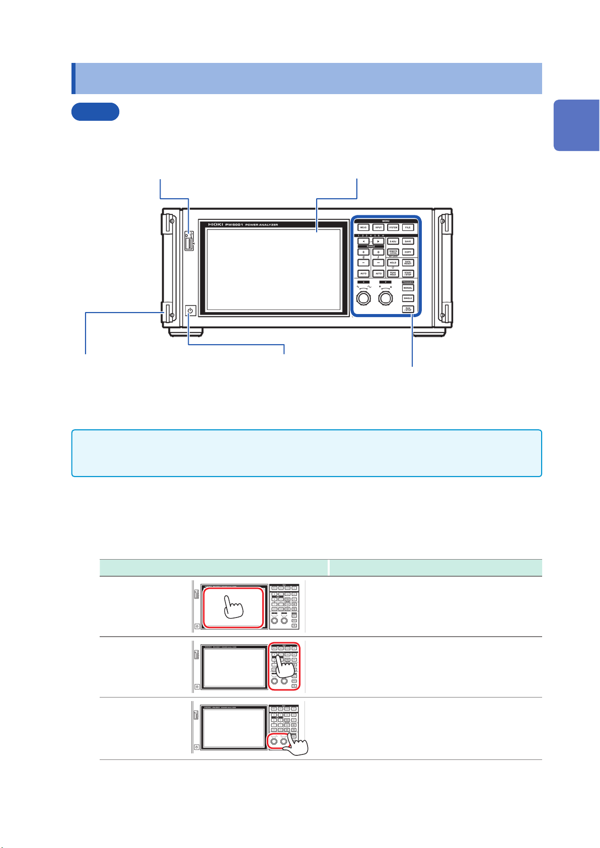
1.3 Part Names and Functions
Front
Part Names and Functions
USB ash drive interface (p. 139)
Connect a USB ash drive to save measurement data,
settings, screenshots, and other data. This interface does
not support use of a mouse, keyboard, or other device.
Handle
Use the handle to carry the
instrument.
Power switch (p. 40)
Turn the instrument on and off.
Display
Touch the touch panel to display measured values and
change settings.
Control area (p. 20)
1
Overview
• Both key operation and touch panel operation are completely disabled while the key lock function is
active, with the exception of key operation used to cancel the key lock state (p. 21).
• The key lock state will persist even if the instrument’s power is cycled.
Instrument operation
The instrument is controlled by means of the MENU keys and rotary knobs in the control area and
the display’s touch panel.
Operation Description
Touch
Press
Turn
Touch the touch panel.
Press a control key.
Turn a rotary knob.
19
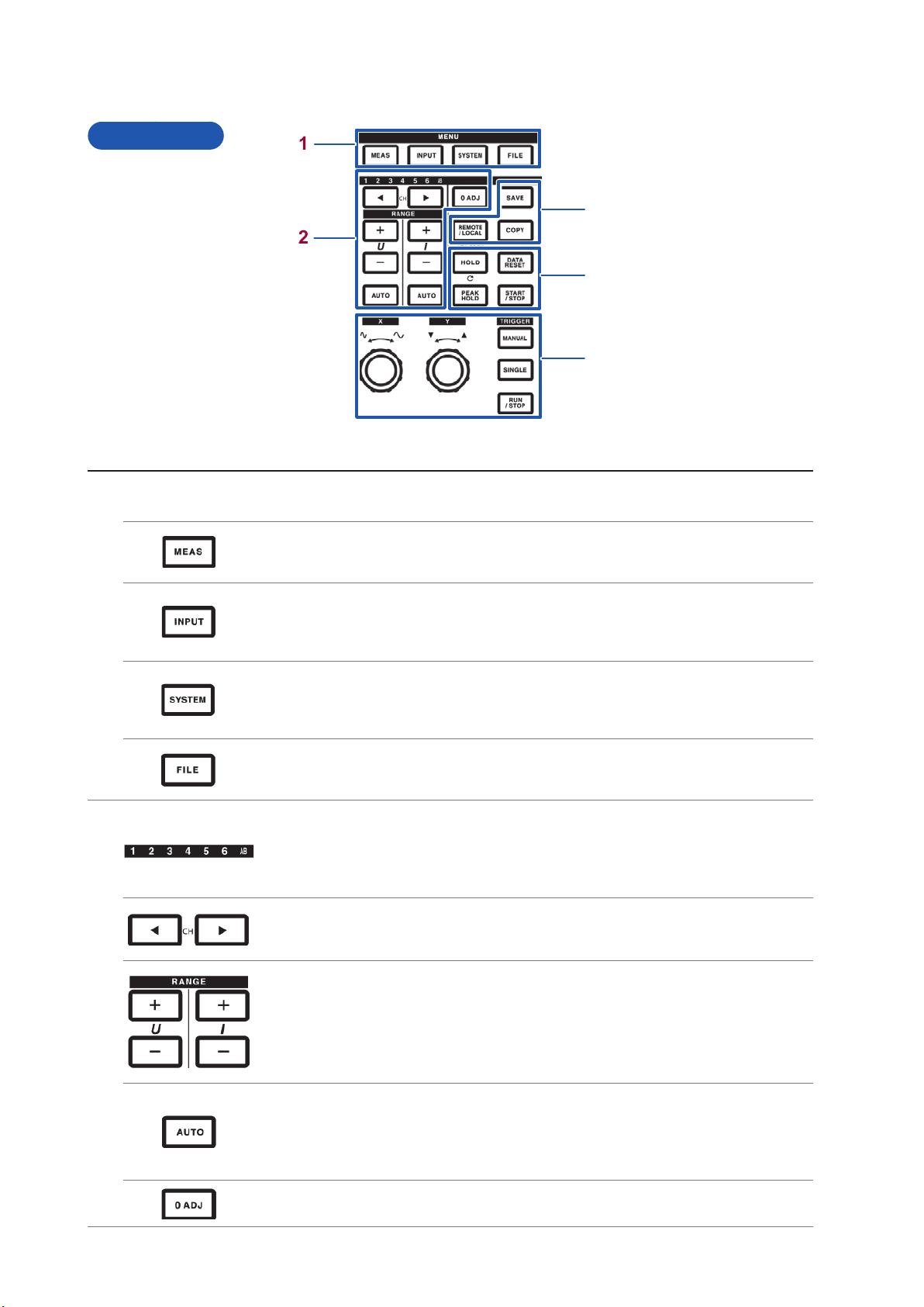
Part Names and Functions
Control area
1
3
2
4
5
MENU keys (switching screens)
1
Pressing a key causes the selected key to light up and the screen to change to the selected screen.
[MEAS] key (p. 30)
Displays the Measurement screen.
The Measurement screen is used to display measured values and waveforms.
[INPUT] key (p. 31)
Displays the Input Settings screen.
The Input Settings screen is used to congure settings related to input, connections, measurement,
and calculations.
[SYSTEM] key (p. 135)
Displays the System Settings screen.
The System Settings screen is used to congure settings related to time control, interfaces, and
overall instrument parameters.
[FILE] key (p. 139)
Displays the File Operations screen.
The File Operations screen is used to manipulate les.
2
Channel indicator LED
• Lights up to indicate the input channel to which the [RANGE] key and setting indicators apply.
• Channels that have been grouped into a connection based on connection settings will light up at
the same time.
• The AB LED corresponds to CH A and CH B on motor analysis and D/A-equipped models.
[CH] keys
• Used to switch the channel whose channel indicator LED is lit up.
• Used to switch the channel on the Basic Settings screen and Harmonic screen.
[RANGE] keys
• The U [+/-] keys change the voltage range, while the I [+/-] keys change the current range.
• Changes apply to the channel whose channel indicator LED is lit up.
• When the AB LED is lit up, the U buttons apply to CH A analog input, while the I buttons apply to
CH B analog input.
• When the [AUTO] key is lit up, AUTO range operation is canceled when the range is changed.
20
[AUTO] keys
• The U [AUTO] key enables the AUTO range function for voltage, while the I [AUTO] key enables
the AUTO range function for current. The key will light up. It will go out if pressed again, and the
range will be xed to the current setting at that time.
• Changes apply to the channel whose channel indicator LED is lit up.
[0ADJ] key (p. 43)
Performs zero adjustment for the input channel.
Part Names and Functions
3
Measurement control keys
4
The measurement control keys function primarily to control power measurement functions. They do not affect the waveform
display.
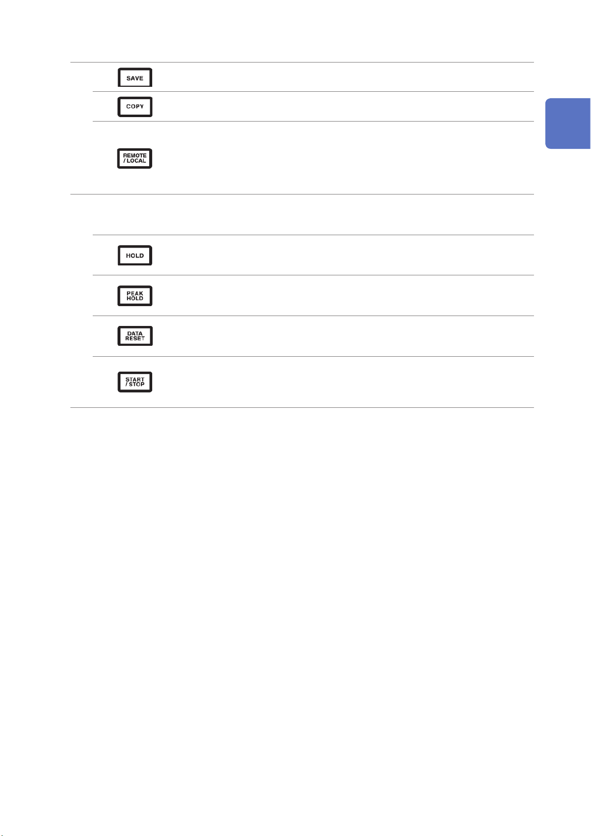
[SAVE] key
Saves the measurement data at the time the key is pressed to the USB ash drive.
[COPY] key
Saves a screenshot of the screen at the time the key is pressed to the USB ash drive.
[REMOTE/LOCAL] key (key lock)
• Lights up when in the remote state for GP-IB communications. Pressing the key again will return
to the local state, causing the light to turn off.
• Pressing and holding the key for 3 sec. or more will enable the key lock function, causing the key
lock icon to be displayed on the screen. Pressing and holding the key again for 3 sec. or more will
cancel the key lock, causing the light to turn off.
[HOLD] key
• Toggles the hold function on and off. The key lights up when the hold function is on.
• Pressing the [HOLD] key while the peak hold function is on will clear the peak hold data.
[PEAK HOLD] key
• Toggles the peak hold function on and off. The key lights up when the peak hold function is on.
• Pressing the [PEAK HOLD] key while the hold function is on will update the hold data.
[DATA RESET] key
• Resets integration data.
• The key functions while the [START/STOP] key is lit up (red).
1
Overview
[START/STOP] key
• Controls starting and stopping of the integration and automatic save functions.
• It lights up when operation starts (green) and when operation stops (red).
• It turns off when the [DATA RESET] key is pressed.
21
Part Names and Functions
Waveform control keys (rotary knobs)
5
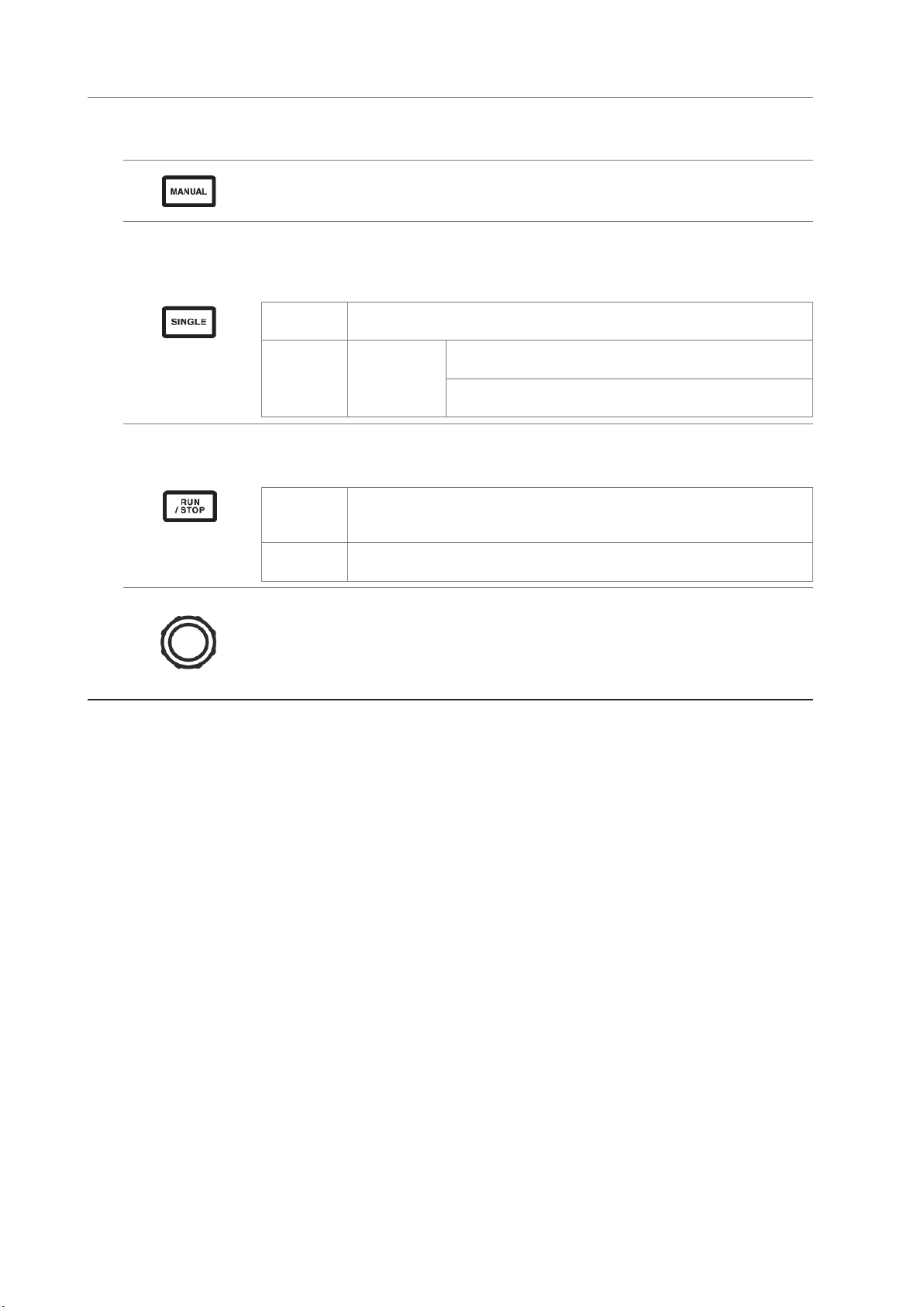
The waveform control keys function primarily to control waveform capture. They operate independently of the instrument’s
power measurement functionality.
[MANUAL] key (manual trigger function)
• Forcibly applies a trigger while waiting for a trigger.
• The trigger is applied when the key is pressed, causing recording to start.
[SINGLE] key
• Performs one waveform capture.
• The key lights up (green) when pressed. Once the trigger is applied and the waveform captured, it
turns off.
Lit up (green)
Off
The instrument is waiting for a trigger.
Recording will start when the trigger is applied.
Recording will stop once data has been recorded for the
[RUN/STOP]:
Lit up (red)
recording length.
Pressing [RUN/STOP] while the instrument is waiting for a trigger
will cause recording to stop.
[RUN/STOP] key
• Causes waveform to be recorded continuously.
• The key lights up (turns green) when pressed and then turns red when pressed again.
Lit up
(green)
Lit up
(red)
The instrument enters the trigger standby state.
Recording will start when the trigger is applied.
The instrument will repeatedly wait for a trigger.
Recording will stop.
Rotary knobs
• The rotary knobs function primarily to zoom waveforms in or out and to change the position or
cursor.
• They are also used with certain settings to vary (increase/decrease) values.
• Each knob operates as appropriate when turned or pressed while lit up but does nothing if the
light is off.
22
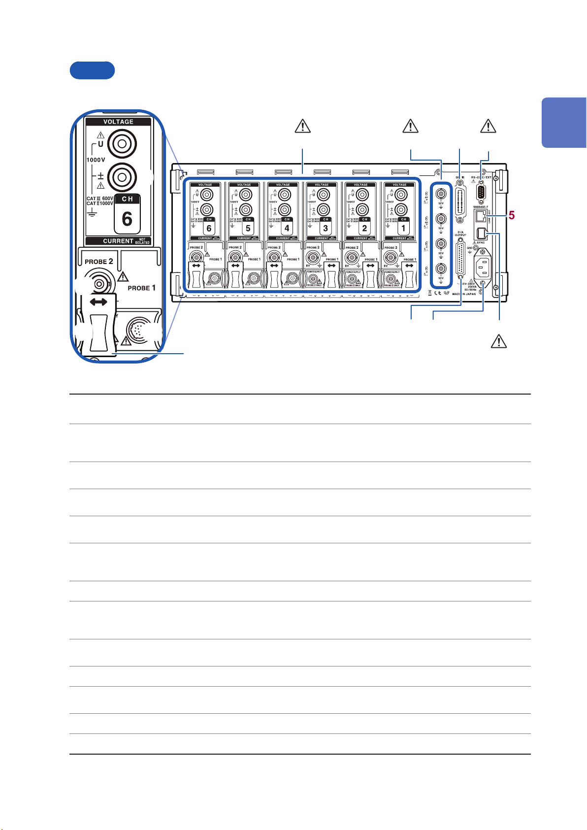
Back
10
Part Names and Functions
(p. 13) ,
(p. 15)
(p. 201)(p. 13)
1
1 2
9
3 4
Overview
5
11
12
13
Input channels 1 through 6
1
Motor input (external
2
input) channels (p. 80)
GP-IB connector (p. 198)
3
D-sub 9-pin connector
4
(p. 201)
LAN connector (p. 190)
5
Two-instrument
synchronization connector
6
(p. 169)
Power inlet (p. 35) Connect the included power cord.
7
D/A output connector
8
(p. 173)
Voltage input terminal
9
(p. 35)
Insert up to six channels in the form of units that accept input of voltage and current for one
phase of power.
(Motor analysis and D/A-equipped models only)
• Measure motor efciency.
• Input torque sensor and tachometer output to measure motor output.
• Control the instrument remotely using GP-IB.
• Transfer data to a computer.
• Control the instrument remotely from a computer or controller via serial RS-232C communications.
• Control starting and stopping of integration with a contact switch.
• Control the instrument remotely over a LAN.
• Acquire data.
Perform measurements using two synchronized instruments.
(Motor analysis and D/A-equipped models only)
• Input the instrument’s output into a recorder to record data over an extended period of time.
• Input to an oscilloscope to observe the waveform.
Connect a Hioki-designated voltage cord.
8
7
6
p.14
Probe2 terminal (p. 38) Connect a Hioki 3270 series current probe for wideband current measurement.
10
Probe2 power supply
11
terminal (p. 38)
Probe1 terminal (p. 37) Connect a CT6800 series current sensor for high-precision current measurement.
12
Sliding cover Slide open the cover to select the current sensor being used.
13
Connect a 3270 series current probe.
23
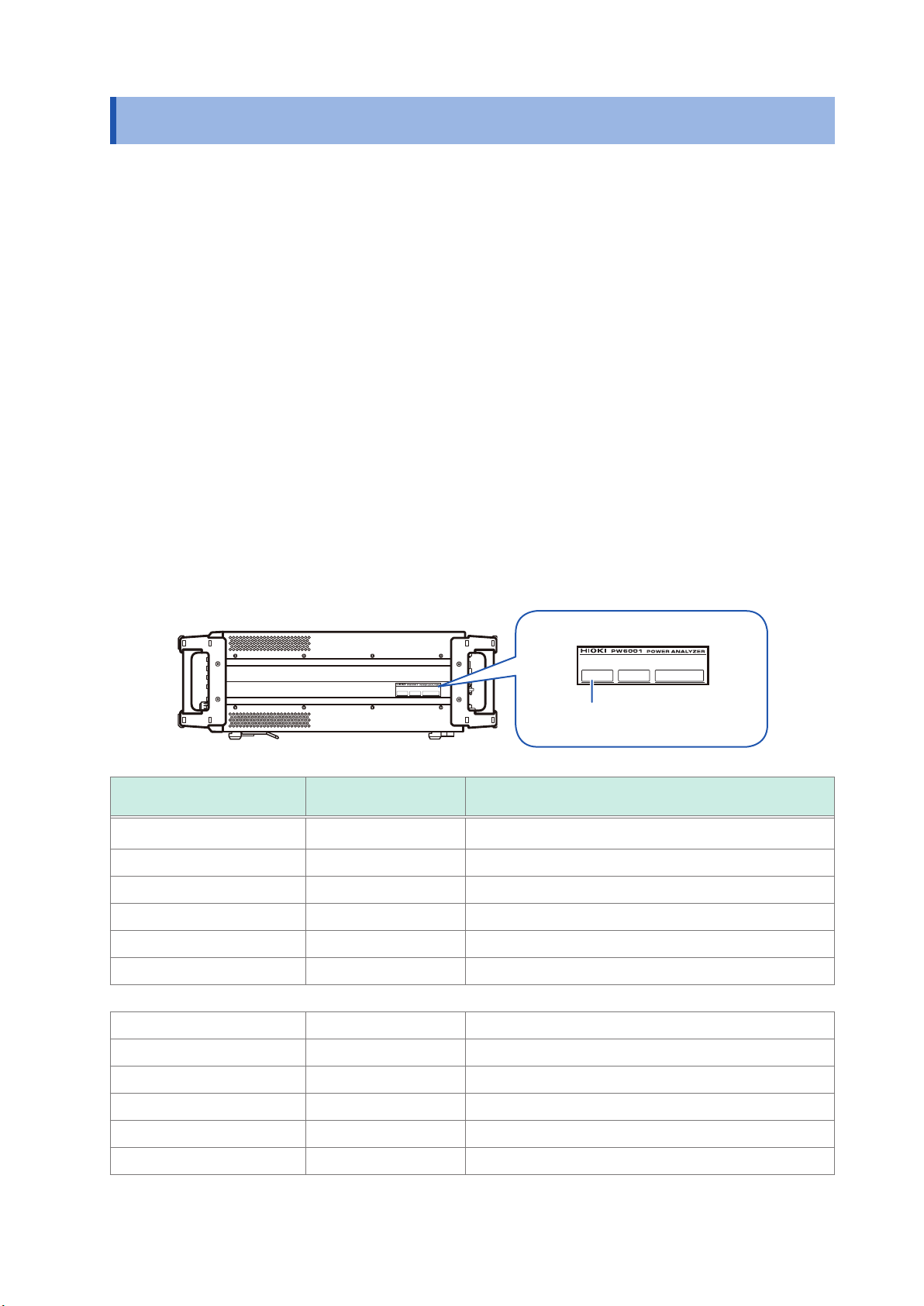
Part Names and Functions
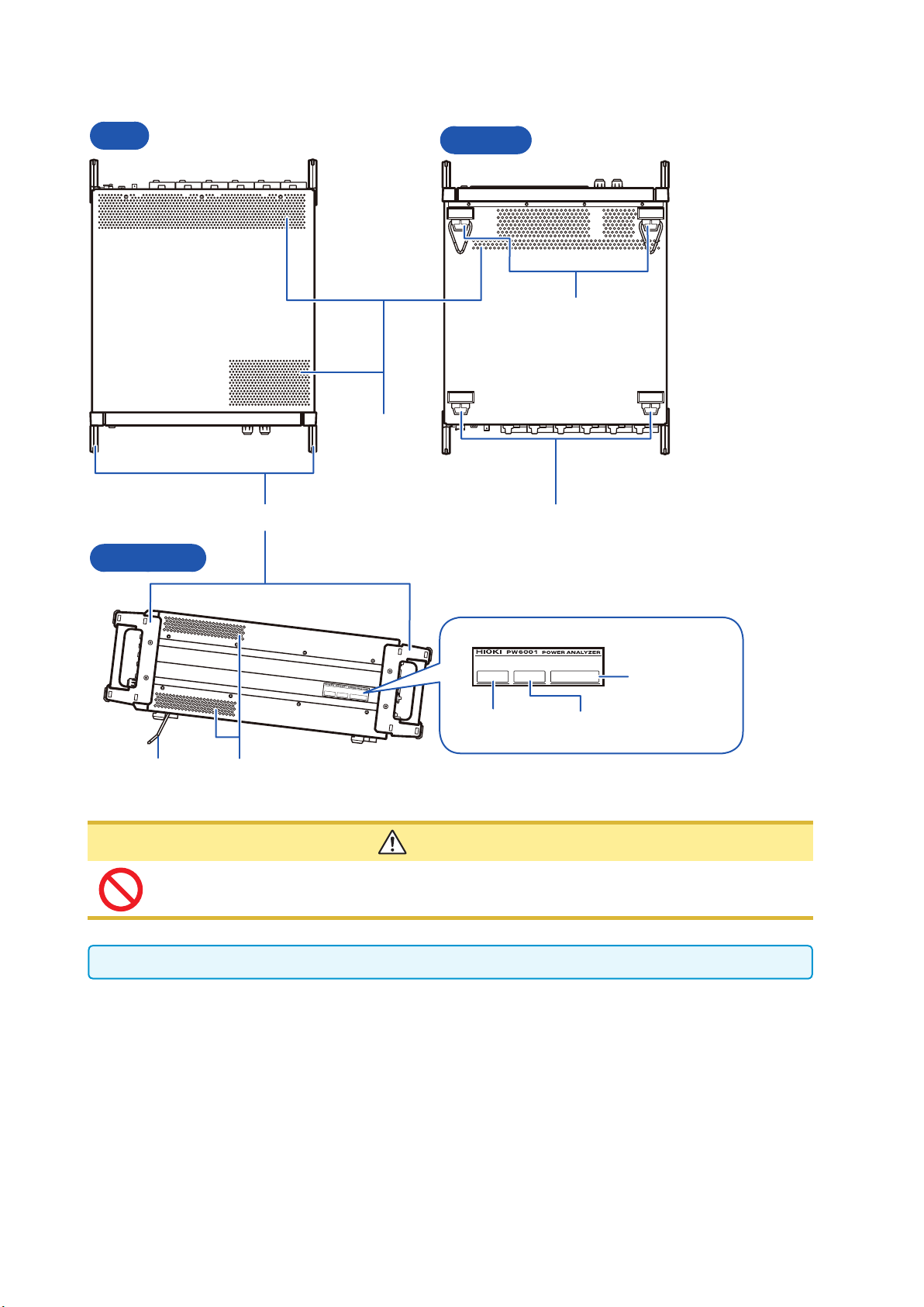
Top
Right side
Handles
Bottom
Support legs
(With stand)
Air vents
Support legs
Serial number
Model number MAC address
Stand
Air vents
CAUTION
Do not subject the instrument to excessive force from above while using the stand. Doing so
may damage the stand.
Leave at least 20 mm between the instrument’s air vents and surrounding surfaces.
24
 Loading...