

Hioki PW3390, PW3390-02, PW3390-01, PW3390-03 Instruction Manual


Contents
Introduction.................................................................................1
i
Contents
1
Confirming Package Contents....................................................2
Safety Notes...............................................................................4
Usage Notes...............................................................................7
Chapter 1
Overview __________________________________ 11
1.1 Product Overview.............................................................. 11
1.2 Features............................................................................ 12
1.3 Operating Overview .......................................................... 14
Chapter 2
Names and Functions of Parts,
Basic Operations & Screens__________________ 15
2.1 Names and Functions of Parts.......................................... 15
2.2 Basic Operations............................................................... 18
2
3
4
5
6
7
2.3 Display Items and Screen Types ...................................... 19
2.3.1 Common Display Items .......................................................... 19
2.3.2 Measurement Screen ............................................................. 20
2.3.3 Screen Types ......................................................................... 21
Chapter 3
Measurement Preparations___________________ 25
3.1 Operations in general........................................................ 25
3.2 Initial Instrument Preparations .......................................... 26
3.3 Pre-Operation Inspection .................................................. 28
3.4 Connecting the Power Cord.............................................. 29
3.5 Grounding the Instrument's Functional Earth
(when measuring in noisy environments) .........................29
3.6 Connecting the Voltage Measurement Cables ................. 30
3.7 Connecting the Current Sensors....................................... 30
3.8 Turning the Power On and Off .......................................... 33
8
9
10
11
12
付
3.9 Selecting the Wiring Mode ................................................ 34
3.10 Setting the Current Sensors.............................................. 38
PW3390A961-01
録
索
引

ii
Contents
3.11 Attaching to the Lines to be Measured and Zero Adjustment 41
3.12 Verifying Correct Wiring (Connection Check) ................... 43
Chapter 4
Viewing Measurement Values _________________ 45
4.1 Measurement Value Display Procedure ........................... 45
4.2 Viewing Power Measurements, and Changing the
Measurement Configuration ............................................. 49
4.2.1 Displaying Power Measurements .......................................... 49
4.2.2 Selecting Ranges................................................................... 51
4.2.3 Selecting the Sync Source..................................................... 56
4.2.4 Frequency Measurement Settings......................................... 58
4.2.5 Selecting the Rectification Method......................................... 60
4.2.6 Setting Scaling (when using VT(PT) or CT)........................... 61
4.2.7 Setting the Low-Pass Filter.................................................... 62
4.3 Integration Value Observation .......................................... 63
4.3.1 Displaying Integration Values ................................................ 63
4.3.2 Setting the Integration Mode.................................................. 66
4.3.3 Manual Integration Method .................................................... 67
4.3.4 Integration Combined with Timing Control............................. 69
4.4 Viewing Harmonic Measurement Values.......................... 72
4.4.1 Displaying the Harmonic Bar Graph ...................................... 72
4.4.2 Displaying the Harmonic List ................................................. 74
4.4.3 Displaying Harmonic Vectors................................................. 75
4.4.4 Selecting the Harmonic Sync Source .................................... 77
4.4.5 Selecting the THD Calculation Method.................................. 78
4.5 Viewing Waveforms .......................................................... 79
4.5.1 Displaying Waveforms ........................................................... 79
4.5.2 Resizing Waveforms.............................................................. 82
4.6 Viewing Noise Measurement Values (FFT Function) ....... 83
4.6.1 Displaying Noise Voltage and Current................................... 83
4.6.2 Setting the Sampling Frequency and Points.......................... 85
4.6.3 Setting the Minimum Noise Frequency.................................. 86
4.6.4 Measurement Channel and Window Function Settings......... 88
4.7 Viewing Efficiency and Loss Measurement Values .......... 89
4.7.1 Displaying Efficiency and Loss .............................................. 89
4.7.2 Selecting the Calculation Formula ......................................... 90
4.7.3 Measurement Examples ........................................................ 91
4.8 Viewing Motor Measurement Values
(Model PW3390-03 only) ................................................. 94
4.8.1 Motor Input Settings............................................................... 96

4.8.2 Measuring Motor Electrical Angle......................................... 102
4.8.3 Detecting the Motor Rotation Direction................................. 105
Chapter 5
Operating Functions _______________________ 107
5.1 Timing Control Functions ................................................ 107
5.2 Averaging Function ......................................................... 110
5.3 Data Hold and Peak Hold Functions............................... 112
5.3.1 Data Hold Function............................................................... 112
5.3.2 Peak Hold Function .............................................................. 113
5.4 X-Y Plot Function ............................................................ 115
5.5 Delta Star Transform Function........................................ 116
iii
Contents
11
12
12
13
3
4
4
5.6 Selecting the Calculation Method ................................... 118
5.7 Trend Function................................................................ 119
Chapter 6
Changing System Settings __________________ 127
6.1 Initializing the Instrument (System Reset) ...................... 130
6.2 Factory Default Settings.................................................. 131
Chapter 7
Data Saving and File Operations _____________ 133
7.1 Inserting and Removing Storage Media.......................... 134
7.2 The File Operation Screen.............................................. 136
7.3 Media Formatting ............................................................ 137
7.4 Saving Operations .......................................................... 138
7.5 Measurement Data Saving ............................................. 139
5
5
6
6
7
7
8
9
10
7.5.1 Manually Saving Measurement Data.................................... 139
7.5.2 Auto-Saving Measurement Data .......................................... 141
7.5.3 Selecting Measurement Items to Save................................. 143
7.6 Saving Noise Data and Waveform Data ......................... 145
7.6.1 Saving Noise Data................................................................ 145
7.6.2 Saving Wave Data................................................................ 146
7.7 Saving Screen Capture Images ...................................... 147
7.8 Loading Screenshots ...................................................... 148
7.9 Saving Setting Configurations......................................... 149
7.10 Reloading Setting Configurations ................................... 150
11
付
録
索
引

iv
Contents
7.11 File and Folder Operations ............................................. 151
7.11.1 Creating Folders .................................................................. 151
7.11.2 Copying Files and Folders ................................................... 152
7.11.3 Deleting Files and Folders ................................................... 154
7.11.4 Renaming Files and Folders ................................................ 155
Chapter 8
Connecting External Devices ________________157
8.1 Connecting Multiple PW3390
(Synchronized Measurements) ....................................... 157
8.2 Controlling Integration with External Signals .................. 161
8.3 Using Analog and Waveform D/A Output ....................... 164
8.3.1 Connecting Application-Specific Devices to the Instrument. 164
8.3.2 Output Item Selection .......................................................... 166
8.3.3 Output Level ........................................................................ 169
8.3.4 D/A Output Examples .......................................................... 170
8.4 Connecting the Instrument to a LR8410 Link-compatible Logger .......... 172
8.4.1 Configuring and Connecting the Adapter............................. 173
8.5 Using the Motor Testing.................................................. 174
Chapter 9
Operation with a Computer __________________177
9.1 Control and Measurement via Ethernet ("LAN") Interface 178
9.1.1 LAN Settings and Network Environment
Configuration 178
9.1.2 Instrument Connection......................................................... 180
9.2 Remote Control of the Instrument by Internet Browser .. 182
9.2.1 Connecting to the Instrument............................................... 182
9.2.2 Operating Procedure ........................................................... 183
9.3 Control and Measurement via USB Interface ................. 184
9.3.1 Connecting to the Instrument............................................... 184
9.3.2 After Connecting .................................................................. 184
9.4 Control and Measurement via RS-232C Interface.......... 185
9.4.1 Connecting to the Instrument............................................... 185
9.4.2 Setting the RS-232C Communications Speed..................... 186
Chapter 10
Specifications _____________________________ 189
10.1 General Specifications.................................................... 189
10.2 Basic Specifications........................................................ 190

10.3 Functions Specifications ................................................. 199
10.4 Setting Specifications...................................................... 204
10.5 Measurement Item Details .............................................. 207
v
Contents
10.6 Calculation Formula Specifications................................. 210
10.7 Wiring System Diagram Specifications ........................... 217
Chapter 11
Maintenance and Service ___________________ 219
11.1 Cleaning.......................................................................... 219
11.2 Trouble Shooting............................................................. 219
11.3 Error Indication................................................................ 222
11.4 Disposing of the Instrument ............................................ 226
Appendix__________________________________A1
Appendix 1Block Diagram ............................................................ A1
Appendix 2Measurement Data Saving Format............................. A2
Appendix 3Physical Illustration..................................................... A5
Appendix 4Rack Mounting............................................................ A6
12
12
13
3
4
4
5
5
6
6
7
7
Index ______________________________________ i
8
9
10
11
Appendix
Index

vi
Contents
Introduction
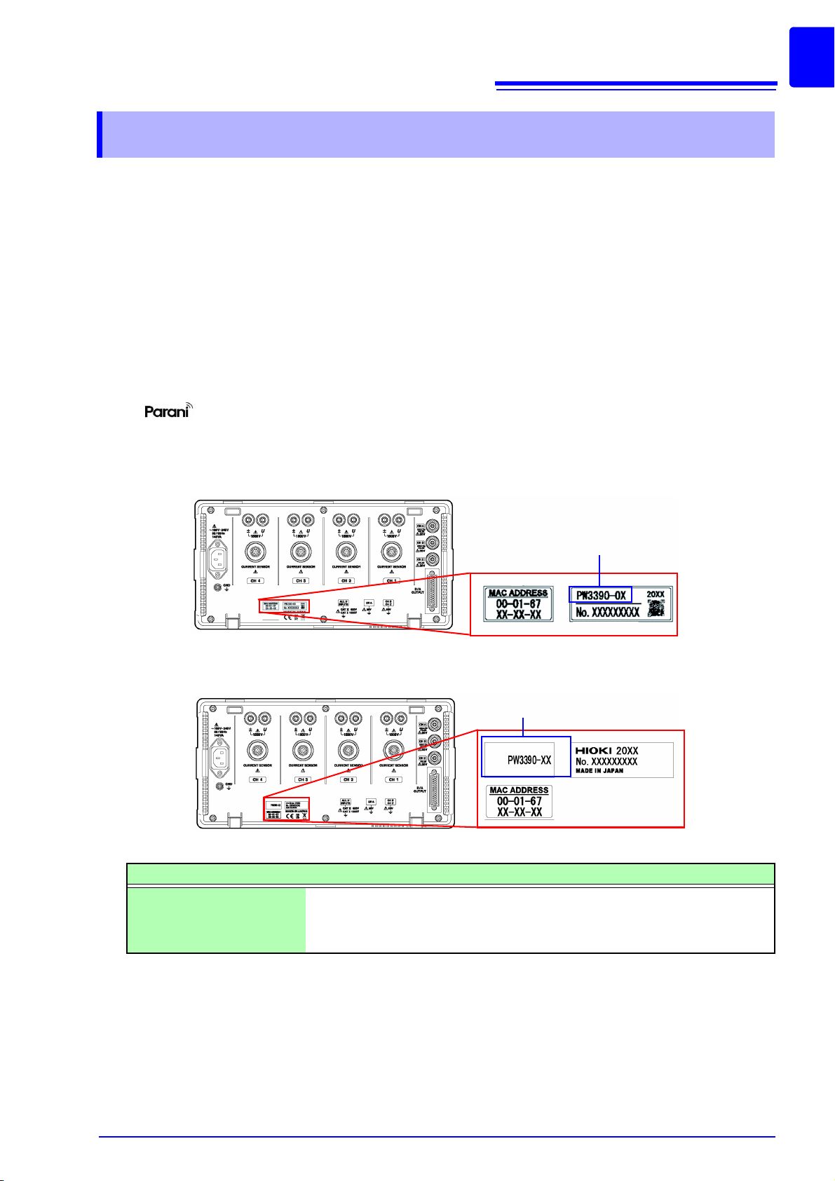
Rear side
The product model number is indicated as below depending on a manufacturing date.
Product model number
Product model number
Introduction
Thank you for purchasing the Hioki PW3390 Power Analyzer. To obtain maximum performance from the
product, please read this manual first, and keep it handy for future reference.
To measure current, the power analyzer requires clamp-on current probes or AC/DC current probes
(Options, (p. 3), afterwards referred to generically as “current sensors”). See your current sensor’s
instruction manual for details.
Trademarks
• CompactFlash is a registered trademark of Sandisk Corporation (USA).
• Microsoft and Windows are either registered trademarks or trademarks of Microsoft Corporation in the
United States and other countries.
• Adobe and Adobe Reader are trademarks of Adobe Systems Incorporated.
• Bluetooth
E.E. CORPORATION under license.
• is a trademark of SENA Technologies Co., Ltd..
is a registered trademark of Bluetooth SIG, Inc.(USA). The trademark is used by HIOKI
1
Product model numbers
Product model number Feature
PW3390-01 Basic model (model without motor analysis and D/A output)
PW3390-02 Model with D/A output
PW3390-03 Model with motor analysis and D/A output
2
Confirming Package Contents
Confirming Package Contents
When you receive the instrument, inspect it carefully to ensure that no damage occurred during shipping.
In particular, check the accessories, panel switches, and connectors. If damage is evident, or if it fails to
operate according to the specifications, contact your authorized Hioki distributor or reseller.
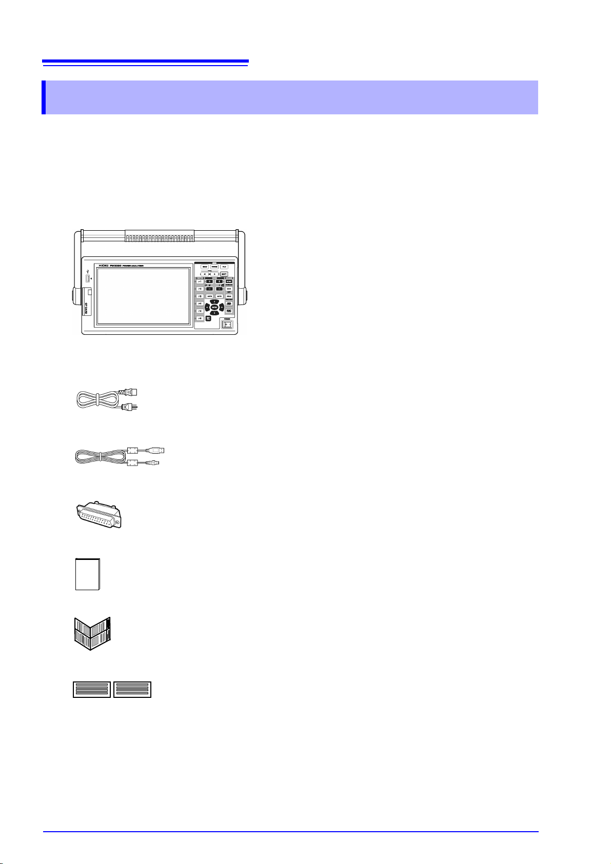
Confirm that these contents are provided.
Main instrument
PW3390 Power Analyzer ×1
Accessories
Grounded power cord ×1
USB cable
D-Sub connector
Instruction manual
Measurement guide
×1
×1 (used only with the D/A output function-equipped PW3390-02 or PW3390-03)
×1
×1
Input cable labels (to identify voltage cords and current sensor channels)
Please attach to the instrument before use. (p. 26)
×2

Options
Current measurement options
• 9272-05 Clamp On Sensor (20 A/200 A AC)
• CT6841-05 AC/DC Current Probe (20 A)
• CT6843-05 AC/DC Current Probe (200 A)
• CT6844-05 AC/DC Current Probe (500 A, 20 mm)
• CT6845-05 AC/DC Current Probe (500 A, 50 mm)
• CT6846-05 AC/DC Current Probe (1000 A)
• PW9100-03 AC/DC Current Box (50 A, 3 channels)
• PW9100-04 AC/DC Current Box (50 A, 4 channels)
• CT6862-05 AC/DC Current Sensor (50 A)
• CT6863-05 AC/DC Current Sensor (200 A)
• 9709-05 AC/DC Current Sensor (500 A)
• CT6904 AC/DC Current Sensor (500 A)
• CT6865-05 AC/DC Current Sensor (1000 A)
• CT9557 Sensor Unit (sensor power supply with 4-channel addition function)
• CT9904 Connection Cable (for connecting the CT9557)
• CT9900 Conversion Cable (PL23 receptacle/ME15W plug)
• Special-order: 5 A rated version of the PW9100
• Special-order: 2000 A pass-through sensor
• Special-order: High-accuracy version of the 9709-05
• Special-order: High-accuracy version of the CT6862-05
• Special-order: High-accuracy version of the CT6863-05
• CT7742 AC/DC Auto-Zero Current Sensor (2000 A)
• CT7642 AC/DC Current Sensor (2000 A)
• CT7044 AC Flexible Current Sensor (6000 A, 100 mm)
• CT7045 AC Flexible Current Sensor (6000 A, 180 mm)
• CT7046 AC Flexible Current Sensor (6000 A, 254 mm)
• CT9920 Conversion Cable (PL14 receptacle/ME15W plug)
3
Confirming Package Contents
Voltage measurement options
• L9438-50 Voltage Cord (banana/banana; 1 each red and black; with alligator clips/approx. 3 m)
• L1000 Voltage Cord (banana/banana; 1 each red, yellow, blue, and gray; 4 black; with alligator clips/approx. 3 m)
• L4931 Extension Cable Set (banana/banana; 1 each red and black/
L9438-50 or L1000)
• L1021-01 Patch Cord (branched bananas/banana; 1 red/approx. 0.5 m, for branching the L9438-50 or L1000)
• L1021-02 Patch Cord (branched bananas/banana; 1 black/approx. 0.5 m, for branching the L9438-50 or L1000)
• 9243 Grabber Clip (1 each red and black)
• PW9000 Wiring Adapter (for three-phase 3-wire)
• PW9001 Wiring Adapter (for three-phase 4-wire)
approx.
1.5 m, for extending the
Connection options
• L9217 Connection Cord (isolated BNC/isolated BNC; 1.6 m; for motor analysis input)
See "8.5 Using the Motor Testing" (p. 174)
• Special-order: D/A Output Cable (25-pin D-sub/male BNC; 16-channel conversion/2.5 m)
• 9683 Connection Cable (for synchronization /1.5 m)
See "Connecting Multiple PW3390 (Synchronized Measurements)" (p. 157)
• 9642 LAN Cable (5 m, with straight/cross conversion connector)
• 9637 RS-232C Cable (9pin-9pin/1.8 m, crossing cable)
Other options
• 9728 PC Card 512M (512 MB CF Card + Adapter)
• 9729 PC Card 1G (1 GB CF Card + Adapter)
• 9830 PC Card 2G (2 GB CF Card + Adapter)
• 9794 Carrying Case (PW3390 dedicated hard type)
• Special-order: Rack mounting hardware (EIA/JIS)
4
Safety Notes
Safety Notes
This instrument is designed to comply with IEC 61010 Safety Standards, and has
been thoroughly tested for safety prior to shipment. However, mishandling during use could result in injury or death, as well as damage to the instrument. However, using the instrument in a way not described in this manual may negate the
provided safety features.
Be certain that you understand the instructions and precautions in the manual
before use. We disclaim any responsibility for accidents or injuries not resulting
directly from instrument defects.
This manual contains information and warnings essential for safe operation of the product and for maintaining it in safe operating condition. Before using the product, be sure to carefully read the following
safety notes.
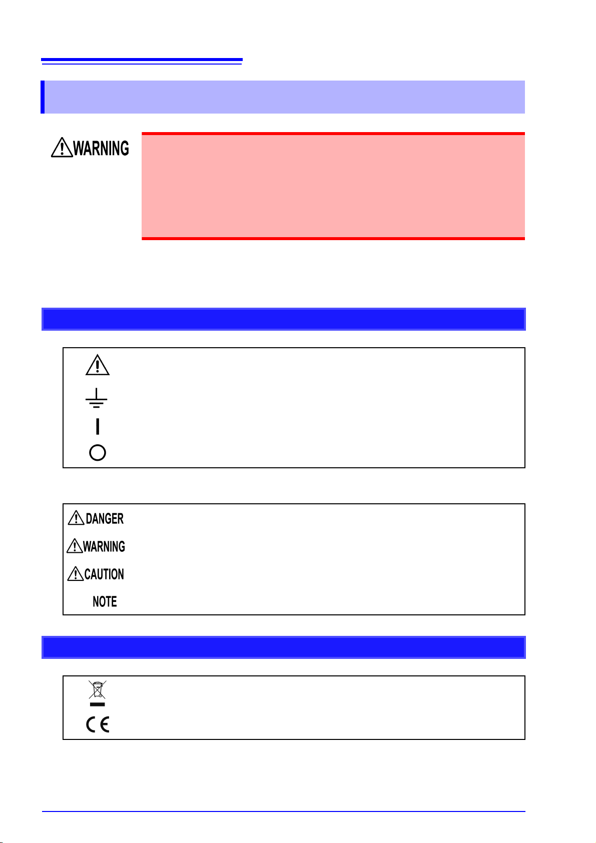
Safety symbols
Indicates cautions and hazards. When the symbol is printed on the instrument, refer to
a corresponding topic in the Instruction Manual.
Indicates a grounding terminal.
Indicates the ON side of the power switch.
Indicates the OFF side of the power switch.
The following symbols in this manual indicate the relative importance of cautions and warnings.
Indicates that incorrect operation presents a significant hazard that could result in serious injury or death to the user.
Indicates that incorrect operation presents a significant hazard that could result in serious injury or death to the user.
Indicates that incorrect operation presents a possibility of injury to the user or damage
to the product.
Advisory items related to performance or correct operation of the product.
Symbols for various standards
Indicates the Waste Electrical and Electronic Equipment Directive (WEEE Directive) in
EU member states.
Indicates that the product conforms to regulations set out by the EU Directive.
Other symbols
Symbols in this manual
Indicates the prohibited action.
(p. ) Indicates the location of reference information.
Indicates quick references for operation and remedies for troubleshooting.
* Indicates that descriptive information is provided below.
[ ] Menus, commands, dialogs, buttons in a dialog, and other names on the screen
and the keys are indicated in brackets.
CURSOR
(Bold character)
Windows Unless otherwise specified, “Windows” represents Windows 7, Windows 8, or Win-
Dialog Dialog box represents a Windows dialog box.
Bold characters within the text indicate operating key labels.
dows 10.
5
Safety Notes
Mouse action terminology
Click: Press and quickly release the left button of the mouse.
Right-click: Press and quickly release the right button of the mouse.
Double click: Quickly click the left button of the mouse twice.
Drag: While holding down the left button of the mouse, move the mouse and then release
the left button to deposit the chosen item in the desired position.
Activate: Click on a window on the screen to activate that window.
Accuracy
We define measurement tolerances in terms of f.s. (full scale), rdg. (reading) and dgt. (digit) values, with
the following meanings:
f.s. (maximum display value or scale length)
The maximum displayable value or scale length. This is usually the name of the
currently selected range.
rdg. (reading or displayed value)
The value currently being measured and indicated on the measuring instrument.
dgt. (resolution)
The smallest displayable unit on a digital measuring instrument, i.e., the input value
that causes the digital display to show a "1" as the least-significant digit.
6
Safety Notes
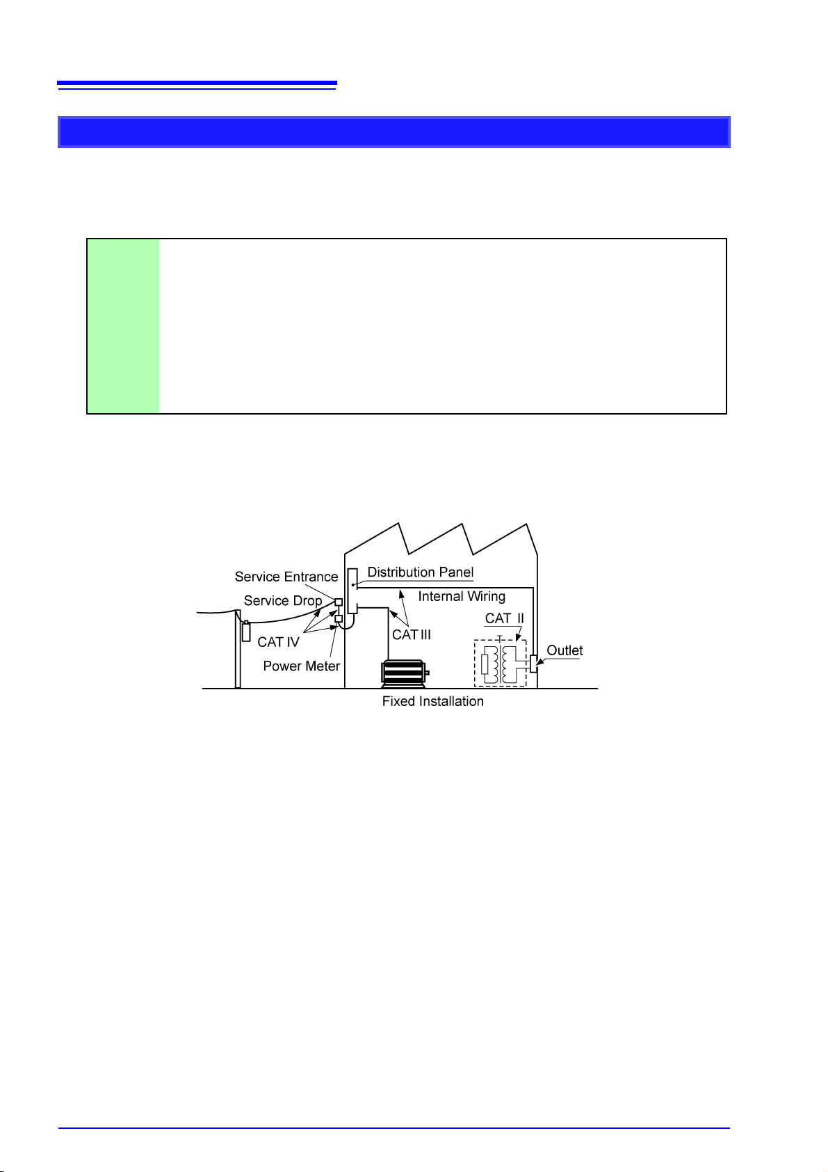
Measurement categories
This instrument complies with CAT II (1000 V) and CAT III (600 V) safety requirements.
To ensure safe operation of measurement instruments, IEC 61010 establishes safety standards for various electrical environments, categorized as CAT II to CAT IV, and called measurement categories.
CAT II Primary electrical circuits in equipment connected to an AC electrical outlet by a power
cord (portable tools, household appliances, etc.) CAT II covers directly measuring electrical outlet receptacles.
CAT II covers directly measuring electrical outlet receptacles.
CAT III Primary electrical circuits of heavy equipment (fixed installations) connected directly to the
distribution panel, and feeders from the distribution panel to outlets.
CAT IV The circuit from the service drop to the service entrance, and to the power meter and pri-
mary overcurrent protection device (distribution panel).
Using a measurement instrument in an environment designated with a higher-numbered category than that for
which the instrument is rated could result in a severe accident, and must be carefully avoided.
Use of a measurement instrument that is not CAT-rated in CAT II to CAT IV measurement applications
could result in a severe accident, and must be carefully avoided.
Usage Notes
50 mm or more
50 mm or more
Usage Notes
Follow these precautions to ensure safe operation and to obtain the full benefits of the various functions.
Before use
Before using the instrument the first time, verify that it operates normally to ensure that the no damage
occurred during storage or shipping. If you find any damage, contact your authorized Hioki distributor or
reseller.
Before using the instrument, make sure that the insulation on the voltage cords
is undamaged and that no bare conductors are improperly exposed. Using the
instrument in such conditions could cause an electric shock, so contact your
authorized Hioki distributor or reseller for replacements.
7
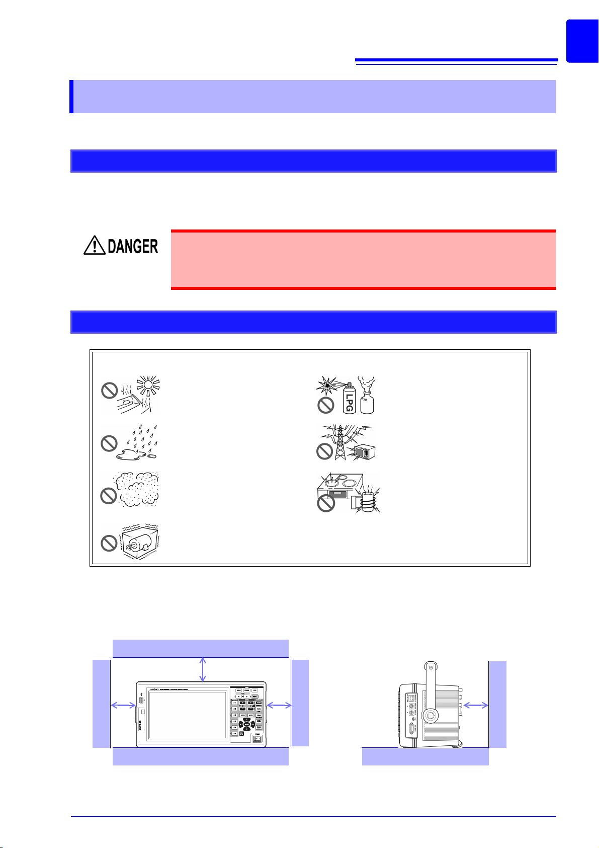
Instrument installation
Avoid the following locations that could cause an accident or damage to the instrument.
Exposed to direct sunlight
Exposed to high temperature
Exposed to liquids
Exposed to high humidity or
condensation
Exposed to high levels of particulate dust
Subject to vibration
In the presence of corrosive or
explosive gases
Exposed to strong electromagnetic fields
Near electromagnetic radiators
Near induction heating systems
(e.g., high-frequency induction
heating systems and IH cooking
utensils)
Installing
• The instrument should be operated only with the bottom or rear side downwards.
• Vents (on the right side of the instrument) must not be obstructed.
8
Usage Notes
Handling the instrument
To avoid electric shock, do not remove the instrument's case. The internal components of the instrument carry high voltages and may become very hot during
operation.
• If the instrument exhibits abnormal operation or display during use, review the information in Troubleshooting section "11.2 Trouble Shooting" (p. 219) and Error Indications section "11.3 Error Indication" (p. 222) before contacting your authorized
Hioki distributor or reseller.
• To avoid damage to the instrument, protect it from physical shock when transporting
and handling. Be especially careful to avoid physical shock from dropping.
• To move the instrument, first disconnect all cables, remove any CF card and USB
memory, and carry it by the handle.
• Do not apply heavy downward pressure with the stand extended. The stand could
be damaged.
See "Using the Handle as a Stand" (p. 15)
• Use a common ground for both the instrument and any devices to be connected.
Using different ground circuits will result in a potential difference between the instrument's ground and the computer's ground. If the communications cable is connected
while such a potential difference exists, it may result in equipment malfunction or
failure.
• Before connecting or disconnecting the communications cable, always turn off the
instrument and any devices to be connected. Failure to do so could result in equipment malfunction or damage.
• After connecting the communications cable, tighten the screws on the connector
securely. Failure to secure the connector could result in equipment malfunction or
damage.
This instrument may cause interference if used in residential areas. Such use must be
avoided unless the user takes special measures to reduce electromagnetic emissions
to prevent interference to the reception of radio and television broadcasts.
Handling the cords and current sensors
Connect the current sensors or voltage cords to the instrument first, and then to
the active lines to be measured. Observe the following to avoid electric shock
and short circuits.
• Do not allow the voltage cord clips to touch two wires at the same time. Never
touch the edge of the metal clips.
• When the current sensor is opened, do not allow the metal part of the clamp to
touch any exposed metal, or to short between two lines, and do not use over
bare conductors.
• To avoid short circuits and potentially life-threatening hazards, never attach the
current sensor to a circuit that operates at more than the maximum rated voltage to earth (See your current sensor's instruction manual for its maximum ratings.)
• Current sensor and voltage cables should only be connected to the secondary
side of a breaker, so the breaker can prevent an accident if a short circuit
occurs. Connections should never be made to the primary side of a breaker,
because unrestricted current flow could cause a serious accident if a short circuit occurs.
• Connect only those voltage cables necessary for measurement.
• To prevent an electric shock accident, confirm that the white or red portion
(insulation layer) inside the cable is not exposed. If a color inside the cable is
exposed, do not use the cable.
9
Usage Notes
• In order to use the CT6862 AC/DC Current Sensor, the line to be measured
must be temporarily disconnected.
To avoid shock and short circuits, turn off the power to lines to be measured
before making connections to terminals to be measured and turning on the
instrument.
• To avoid electric shock, do not exceed the lower of the ratings shown on the
instrument and test leads.
• To avoid electric shock and short-circuit accidents, use only the specified voltage
cord to connect the instrument input terminals to the circuit to be tested.
• For safety reasons, when taking measurements, only use the optional voltage cord.
Avoid stepping on or pinching cables, which could damage the cable insulation.
• To avoid breaking the cables, do not bend or pull them.
• To avoid damaging the power cord, grasp the plug, not the cord, when unplugging it
from the power outlet.
• Keep the cables well away from heat sources, as bare conductors could be exposed
if the insulation melts.
• Be careful to avoid dropping the current sensors or otherwise subjecting them to
mechanical shock, which could damage the mating surfaces of the core and
adversely affect measurement.
• Be careful when handling the cords, since the conductor being measured may
become very hot.
• When disconnecting the connector, be sure to release the lock before pulling off the
connector. Forcibly pulling the connector without releasing the lock, or pulling on the
cable, can damage the connector.
• To prevent damage to the instrument and current sensors, never connect or disconnect a sensor while the power is on, or while the sensor is clamped around a conductor.
10
Usage Notes
Before connecting measurement cables
• Do not use the instrument with circuits that exceed its ratings or specifications. Doing so may damage the instrument or cause it to become hot, resulting in bodily injury.
• Never exceed a current sensor’s input current rating. Doing so could destroy
the instrument and cause personal injury.
• Before turning the instrument on, make sure the source voltage matches that
indicated on the instrument's power connector. Connection to an improper
supply voltage may damage the product and present an electrical hazard.
• To avoid electrical accidents and to maintain the safety specifications of this
instrument, connect the power cord provided only to an outlet.
For safety reasons, disconnect the power cord when the instrument is not used.
Before connecting to the lines to be measured
To avoid electrical hazards and damage to the instrument, do not apply voltage
exceeding the rated maximum to the external input terminals.
• To avoid electrical accidents, confirm that all connections are secure. The
increased resistance of loose connections can lead to overheating and fire.
• Ensure that the input does not exceed the maximum input voltage or current to
avoid instrument damage, short-circuiting and electric shock resulting from
heat building.
• When the power is turned off, do not apply voltage or current to the voltage input terminals, current input terminals, or current sensors. Doing so may damage the instrument.
• Note that the instrument may be damaged if the applied voltage or current exceeds
the measurement range.
While measuring
If an abnormality such as smoke, strange sound or offensive smell occurs, stop
measuring immediately, disconnect from the measurement lines, turn off the
instrument, unplug the power cord from the outlet, and undo any changes to the
wiring. Contact your authorized Hioki distributor or reseller as soon as possible.
Continuing to use the instrument may result in fire or electric shock.

11
The Hioki PW3390 Power Analyzer is a high-precision, broad-range instrument for measuring electrical
power from DC to inverter frequencies. Four input channels are provided to support single- and threephase inverter motor system measurements.
For developing and evaluating high efficiency inverter motors
For developing and evaluating alternative energy sources such as solar,
wind power, and fuel cells
For inverter motor maintenance
1.1 Product Overview
1
Overview Chapter 1
1.1 Product Overview
• High precision and stability ensure highly reproducible power measurements
• Electrical phase angle measurements necessary for motor analysis
• Measure motor efficiency by connecting with a high precision torque meter or encoder.
Chapter 1 Overview
• Simultaneously measure AC and DC power.
• Separately measure power input, sold, consumed, and regenerated using the DC mode and the current and integrated power (electrical energy) in RMS mode.
• Save long-term measurement data to high-capacity storage media.
• Easily measure inverter secondary power on site.
• Simultaneously measure primary and secondary inverter power.
• Measure inverter noise.

12
Supports multiple power system configurations
High accuracy over a broad range
Current sensor phase correction function (standard feature)
Provides both fast data processing and high accuracy
Extensive data analysis functions are included as standard features
Simultaneous analysis of all parameters
Supports measurements with both easy-to-use clamp probes and highprecision penetrating probes
1.2 Features
1.2 Features
• Four isolated voltage and current input channels are provided to support simultaneous multisystem measurements such as inverter primary and secondary power.
• Measure power system wiring configurations from single-phase to three-phase, four-wire.
• Broad frequency range (0.5 Hz to 5 kHz fundamental) supports DC to inverter frequencies.
• Basic accuracy is ±0.04% rdg. ±0.05% f.s. at DC and from 0.5 Hz to 200 kHz.
• Precise measurements over a broad range of inverter carrier frequencies: ±0.2% rdg. ±0.1% f.s.
at 10 kHz, and ±1.5% rdg. ±0.5% f.s. at 100 kHz.
• This function utilizes virtual oversampling, a new technology, to correct current sensor phase
errors at a resolution of 0.01
power-factor power components contained in inverter output switching frequencies.
• While maintaining high accuracy, power measurements and harmonic analysis updates every
50 ms.
• During low-frequency measurements, data is automatically updated in sync with frequency, so
no refresh (data update rate) switching is needed when changing from low to high rotation
rates.
• Simultaneously measure RMS, mean, AC and DC components, and fundamental waveforms.
• Perform harmonic analysis up to the 100
kHz.
• Display high-speed waveforms sampled at up to 500 kS/s.
• Perform multifaceted analysis with X-Y graph functions.
, allowing accurate measurement of the high-frequency, low-
th
order and inverter noise (FFT) analysis up to 200
• Simultaneously analyzes harmonics, noise while performing integration, displaying waveforms
and trend graph.
• Select from various AC and AC/DC clamp-on current probes with ranges from 20 A to 1000 A.
• Measure high currents with high precision using clamp-on current sensor probes.
• Clamp-on current probes eliminate the need for problematic direct contact with wiring.
• In-phase effects on inverter measurements are greatly reduced by isolating current sensors
from the measurement objects.

13
Single-unit instrument ideal for portable as well as rack-mount
applications
Variety of interfaces are equipped in standard
PC application program provides remote control and data acquisition (p. 177)
Wiring confirmation function avoids wiring mistakes (p. 43)
Multi-instrument synchronization capability supports additional
measurement channels (p. 157)
Prepared for motor evaluation options (p. 174)
D/A output option for waveform output (p. 164)
Easy-to-see color LCD (p. 15)
1.1 Product Overview
1
• Small and light weight (approx. 4.6 kg), with a convenient carrying handle (p. 15).
• Rack mountable in 170 mm (EIA 4U) vertical space.
• Includes 100 Mbps Ethernet and USB 2.0 High Speed communications interfaces.
• Supports high-speed data communication systems.
• Provides a dedicated front-panel USB port and CF card slot for removable storage devices.
• Supports high-capacity media for high-speed data storage.
• With the instrument connected to a computer by LAN, USB cable, or RS-232C, use the PC
application program to acquire data on the computer and control the instrument remotely.
Download the PC application program from Hioki's website. (http://www.hioki.com)
• Even without the PC application program, the same operations can be performed using a
browser to access the HTTP server function.
• The vector display avoids wiring mistakes by confirming even complicated three-phase wiring.
Chapter 1 Overview
• Measure with up to 8 instruments simultaneously.
• Slave instruments measure and record data in synchronization with the master instrument.
• Using the PC application program, synchronously acquire and record data on up to 8 instruments.
• Motor power can be determined by measuring torque meter output and rotation rate.
• Supports both analog DC and frequency-output-type torque measurement inputs.
• Supports both analog DC and rotation pulse outputs for measurement inputs.
• Supports encoder Z-phase signals for phase measurements with standard encoder pulses.
• Outputs up to 16 analog measurement parameters on 16 D/A output channels.
• Voltage and current waveforms sampled at 500 kHz in the waveform output mode provide
safely isolated voltage and current waveforms for other waveform measuring instruments.
• Includes a 9-inch color TFT LCD.
• Easily view waveforms and graphs on the wide-screen 800 480 dot display.
14
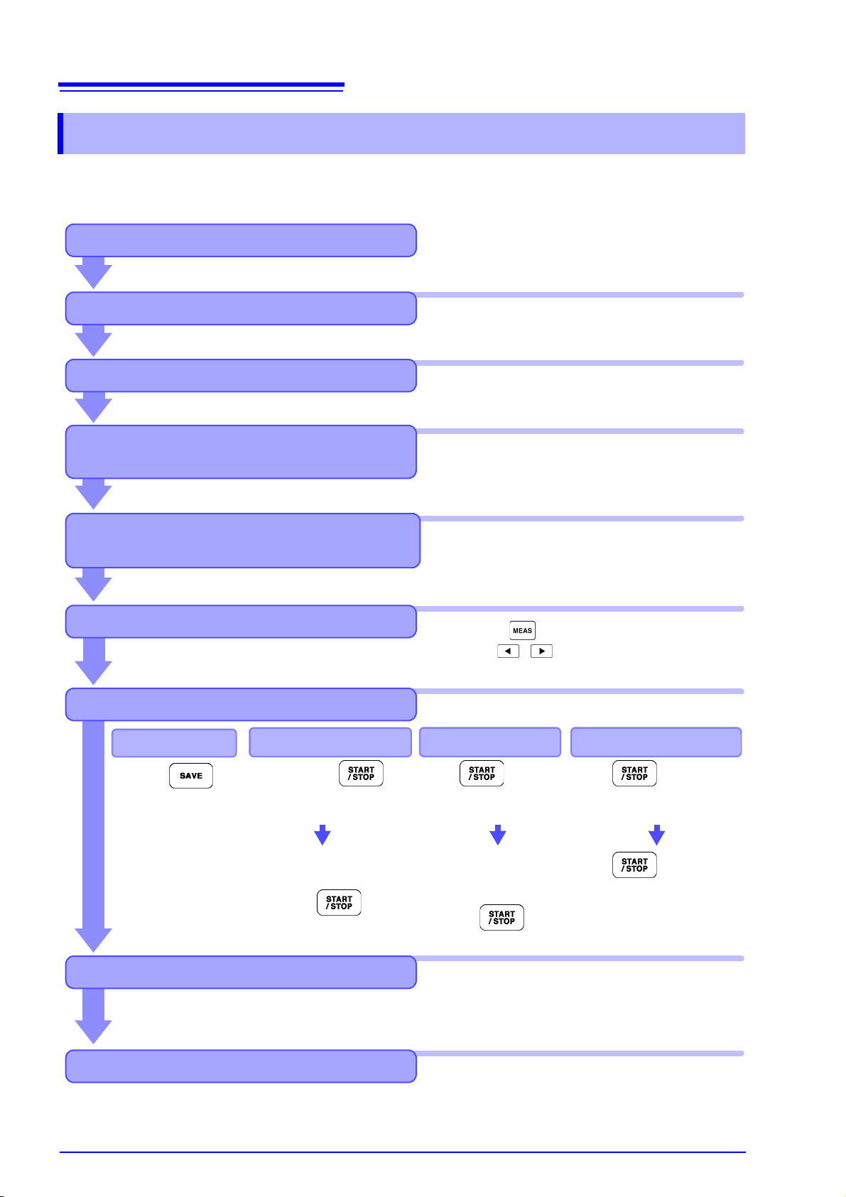
Saving
Turning Power Off
Analyzing Saved Data on a Computer
Installing the Instrument
Initial Instrument Preparations
Stops automatically at the
specified stop time.
Press the key to
force stop.
After pressing
saving starts at the specified start time.
Connect the instrument to a computer with the supplied USB cable or an Ethernet cable and use the
dedicated PC application program to transfer data to
the computer for analysis. This also enables remote
operation and control of the instrument.
See 3.2 ( p.26)
See 3.3 ( p.28)
See 3.4 ( p.29) to 3.8 ( p.33)
See 3.9 ( p.34) to 3.12 ( p.43)
See Chapter 7 ( p.133)
See "Instrument installation" (p. 7)
See Chapter 9 ( p.177)
Press the key, and select display contents
with the and F keys.
See "2.2 Basic Operations" (p. 18)
Viewing Measurement Values
Press the .
Manual saving
Pre-Operation Inspection
Connecting Cables and Probes, and
Turning Power On
Configuring wiring settings and sensor
settings, and checking the wiring
See Section 3.8 ( p.33)
Always perform these checks before connecting, and when turning the power on.
See Chapter 4 ( p.45)
For high-precision measurements, allow at least
30 minutes warm-up after power-on before executing zero adjustment.
Configure current sensor phase correction to
facilitate more precise measurement.
Always execute zero adjustment before connecting to measurement objects.
Press to save
for a specified time
span.
Save timer control
Press to start.
Save the specified time span.
Press to stop.
When the timer and real-time
control are set, stops at the
specified time.
Stops automatically
when the specified time
has elapsed.
Press the key to
force stop.
Save interval control
Save in realtimecontrol
1.3 Operating Overview
1.3 Operating Overview
Be sure to read "Usage Notes" (p. 7) before measuring.
Follow the procedures below to perform measurements. Data saving and analysis on the computer can
be performed as necessary.
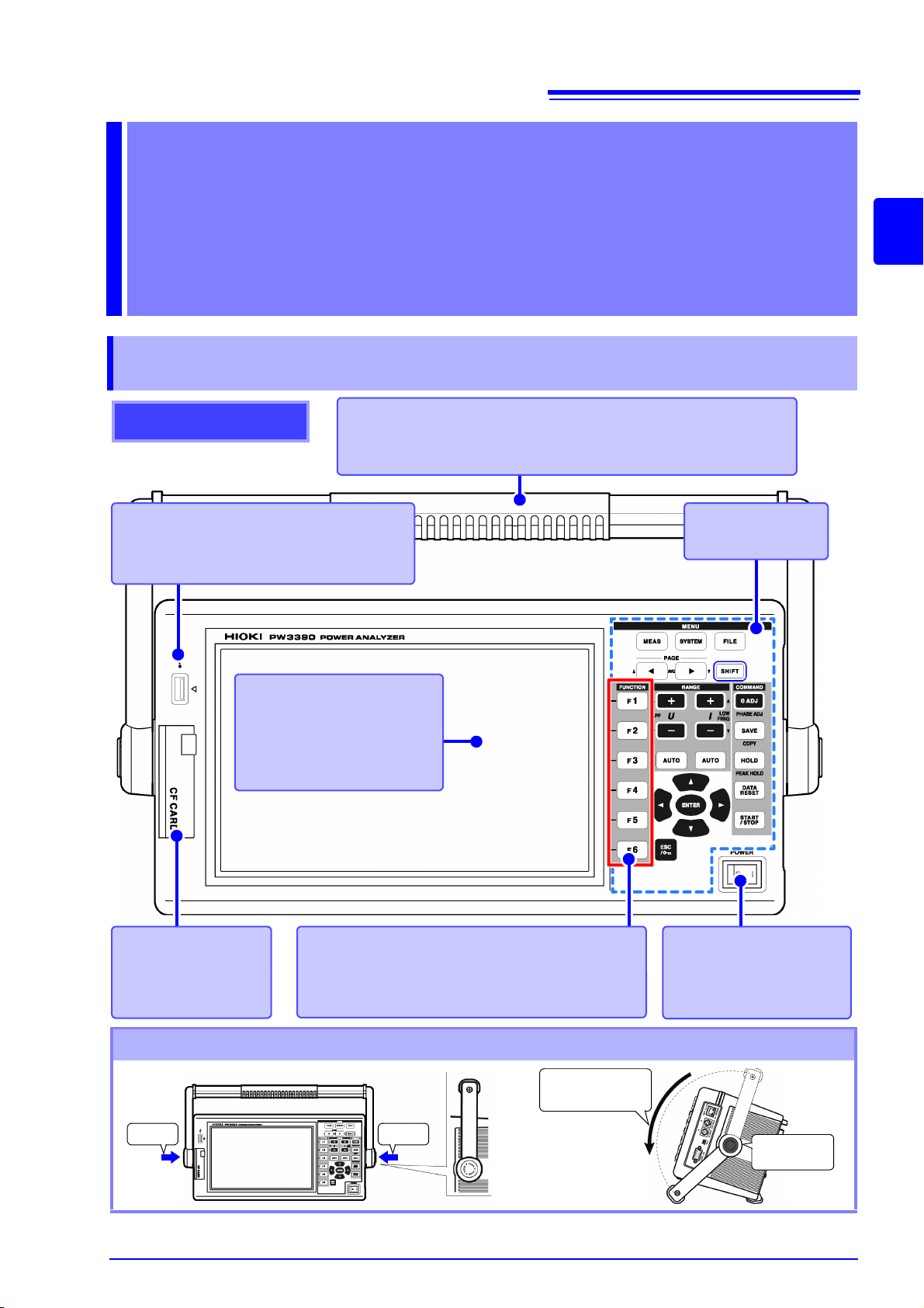
2.1 Names and Functions of Parts
Display
Displays the Measurement,
Setting, or File Operation
screen.
See p. 19
CF card interface
Insert a CF card.
See p. 134
Front
F key (Function key)
Select and change display contents and settings.
See p. 18
Operation keys
See p. 16
Handle
Use to carry the instrument, and fold it down to serve as a stand.
See Bottom part of this page
Power switch
Turns the instrument on
and off.
See p. 33
USB memory interface
Connect a USB flash drive storage device.
See p. 133
Press Press
Keep on
pressing
Rotate the handle
to the click point.
12
Names and Functions of Parts,
Basic Operations
& Screens Chapter 2
2.1 Names and Functions of Parts
15
2
Chapter 2 Names and Functions of Parts, Basic Operations & Screens
Using the Handle as a Stand
16
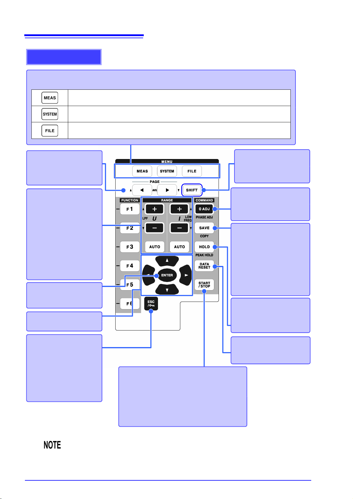
SHIFT key
(Lit when running)
Activates alternate key functions.
START/STOP key
(Lit when running)
Starts and stops integration and saving operations.
To restart integration and saving: Press the DATA
RESET key to reset integration values, then press
this key. (Press the START/STOP key without reset-
ting the integrated value if you wish to add the integration result to the previous one.)
SAVE key
Saves data to the storage
media.
See 7.5.2 (p.141)
(Screen Capture)
Press the SAVE key while
holding the SHIFT key to capture a screen image to the
specified storage media.
(p. 147)
ESC key
Cancels the last change to a
setting, and returns it to its
original state.
(Key-lock)
Hold for three seconds to
toggle the key lock. The key
lock state is indicated at the
top of the screen (p. 19).
Operation keys
DATA RESET key
Resets the integration values.
See 4.3.1 (p.63)
0 ADJ key
Performs zero adjustment and
current sensor degaussing.
See 3.11 (p.41)
HOLD key
(Lit when running)
Toggles the peak-hold function.
See 5.3 (p.112)
RANGE keys
•The U + and – keys change
the voltage measurement
range, and the I + and –
keys change the current
measurement range.
• Pressing the AUTO key
activates Auto Ranging (p.
52).
• These keys also set the lowpass filter (p. 62) and the
lower measurement limit setting (p. 58).
PAGE ke y
• Changes the screen page.
• Allows you to configure
averaging (p. 110).
MENU keys (Screen selection)
Press a key to select a screen (the lit key indicates the current selection).
Displays the Measurement screen for viewing measurement values. Voltage and current ranges can be selected, and low-pass filter settings can be changed.
(p. 21)
Displays the Setting screen for setting measurement criteria, wiring mode (phase systems), wiring check and system environment configuration.
(p. 22)
Displays the File Operation screen for performing file operations on data saved to
storage media, and selecting data file formats.
(p. 23)
ENTER key
Accepts selections and
changes to settings.
CURSOR key
Move the cursors.
2.1 Names and Functions of Parts
• When the key lock function is enabled, all other key operations are disabled.
• The key lock state is retained even when power is off.
17
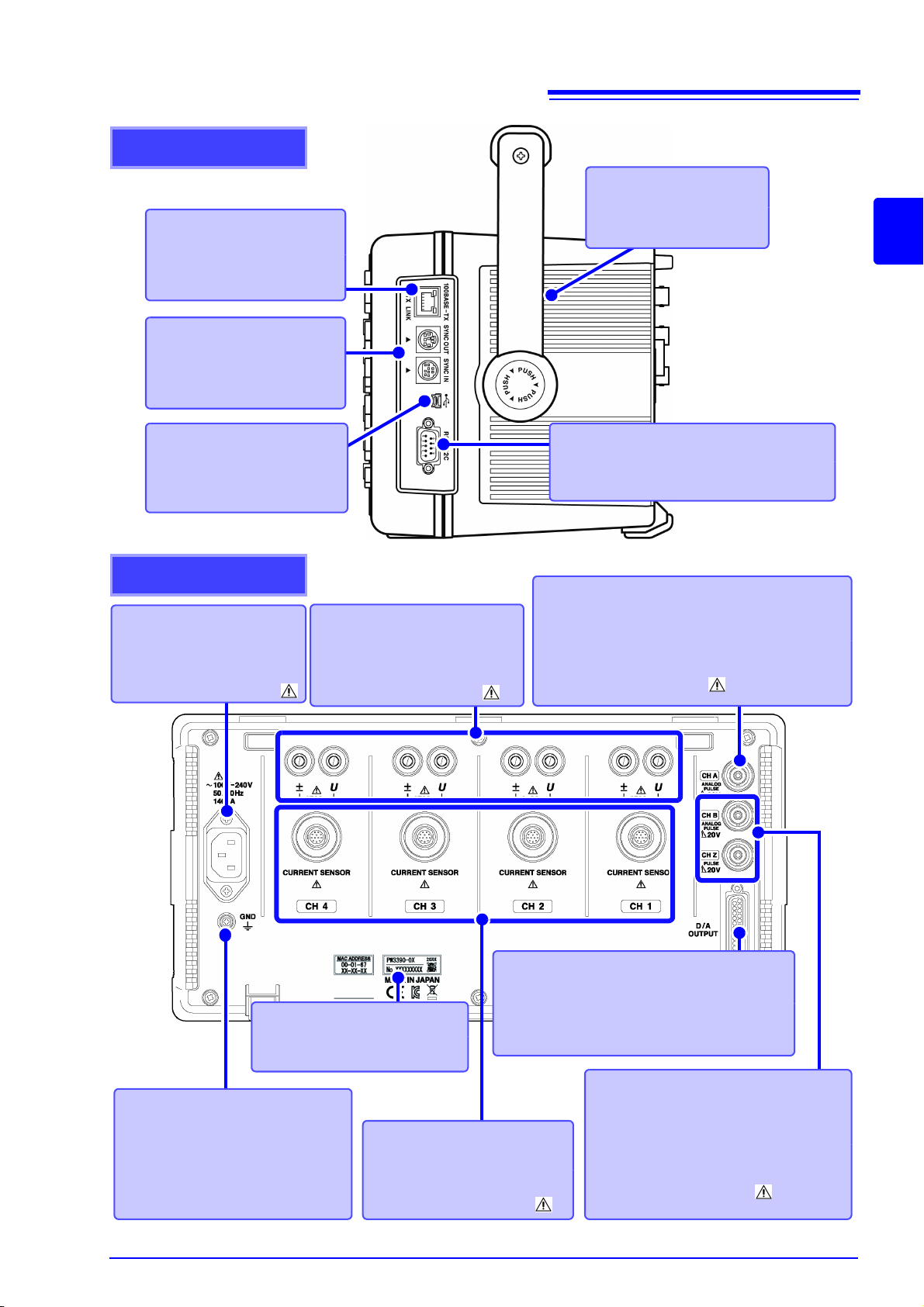
Right side
Ethernet interface jack
For LAN connection with an
Ethernet cable.
See p. 180
Sync interface
For synchronizing cables, as
needed.
See p. 157
Vent
Keep clear of obstructions.
See p. 7
RS-232C interface
For RS-232C cable connection, as needed.
See p. 185
USB port
For the supplied USB cable,
as needed.
See p. 184
Rear side
Voltage input terminals
Connect Hioki-specified voltage
measurement cables.
See p. 30,
"Usage Notes" (p. 7)
Current input terminals
Connect an Hioki-specified current sensor.
See p. 30,
"Usage Notes" (p. 7)
Power inlet
Connect the supplied power
cord.
See p. 29,
"Usage Notes" (p. 7)
Output terminal
Connect the supplied D-sub plug (PW3390-02
[model with D/A output] and PW3390-03 [model with motor analysis and D/A output] only).
See p. 164
CH A torque signal input BNC jack
Connect the Hioki L9217 BNC connection cable to
this terminal (PW3390-03 [model with motor analysis and D/A output] only).
See p. 174,
"Usage Notes" (p. 7)
CH B and CH Z rotation signal
input BNC jacks
Connect the Hioki L9217 Connection
Cord to these t er mi nals (PW3390-03 [model with motor analysis and D/A output] only).
See p. 174,
"Usage Notes" (p. 7)
Serial No.
This is the instrument’s serial
number.
Functional ground terminal
Connect this terminal to a clean
common ground to suppress electrical noise when measuring in an
electrically noisy environment.
See p. 29
2.1 Names and Functions of Parts
2
Chapter 2 Names and Functions of Parts, Basic Operations & Screens
18
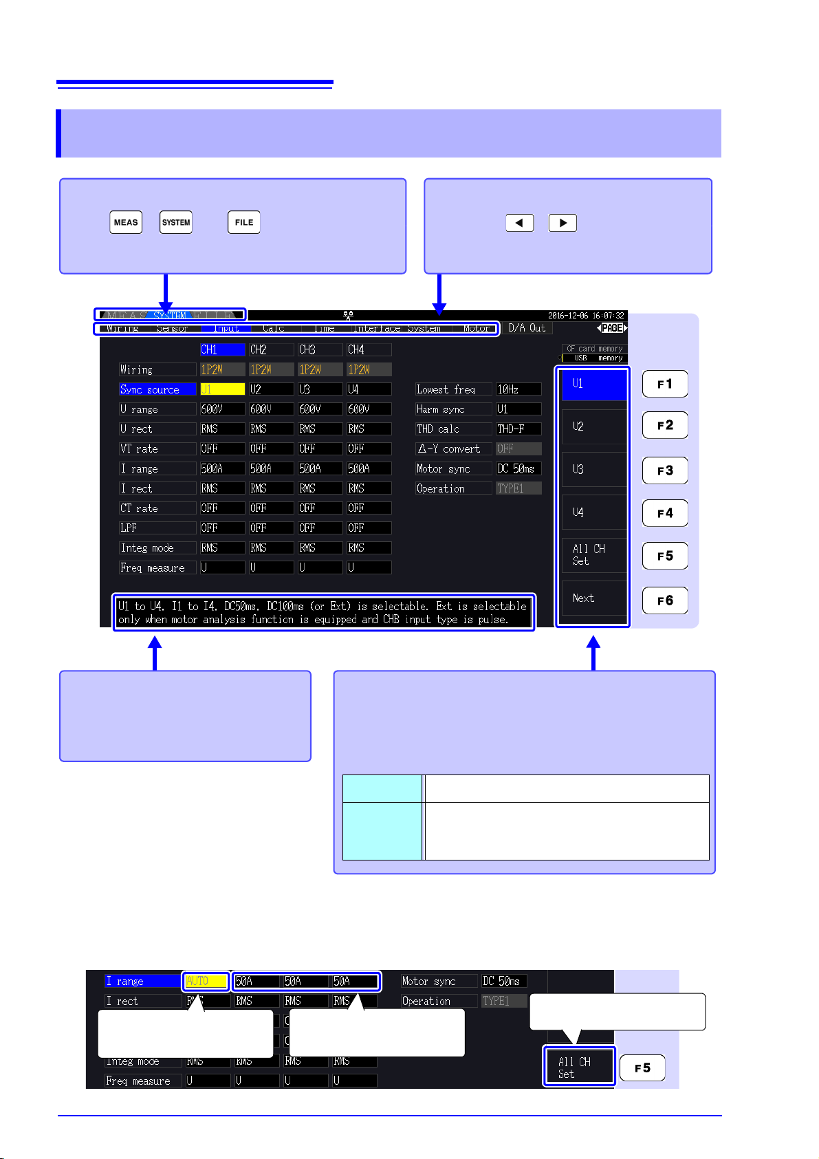
Set any channel to
[AUTO].
1
All channels are set to
[AUTO].
3
Select [All CH Set]
2
To select a display screen
Press , , or to display the corresponding screen.
See p. 21 to p. 23
Help comment
Describes the object at the current
cursor position (only on Setting and
File Operations screens).
Using [All CH Set]
(For example, to enable auto-ranging on all channels.)
CH1 CH2 CH3 CH4
To select the displayed screen page
Press the keys to change.
See p. 21, p. 23
To select and change display contents and settings
Press one of the F keys to select and change display contents and settings. The displayed function labels depend on
the currently displayed screen.
Special Setting Items
All CH Set Select to apply the same setting to all channels.
Next
This appears when more than six setting
items are available. Press F6 to display the
function labels of the additional items.
2.2 Basic Operations
2.2 Basic Operations
2.3 Display Items and Screen Types
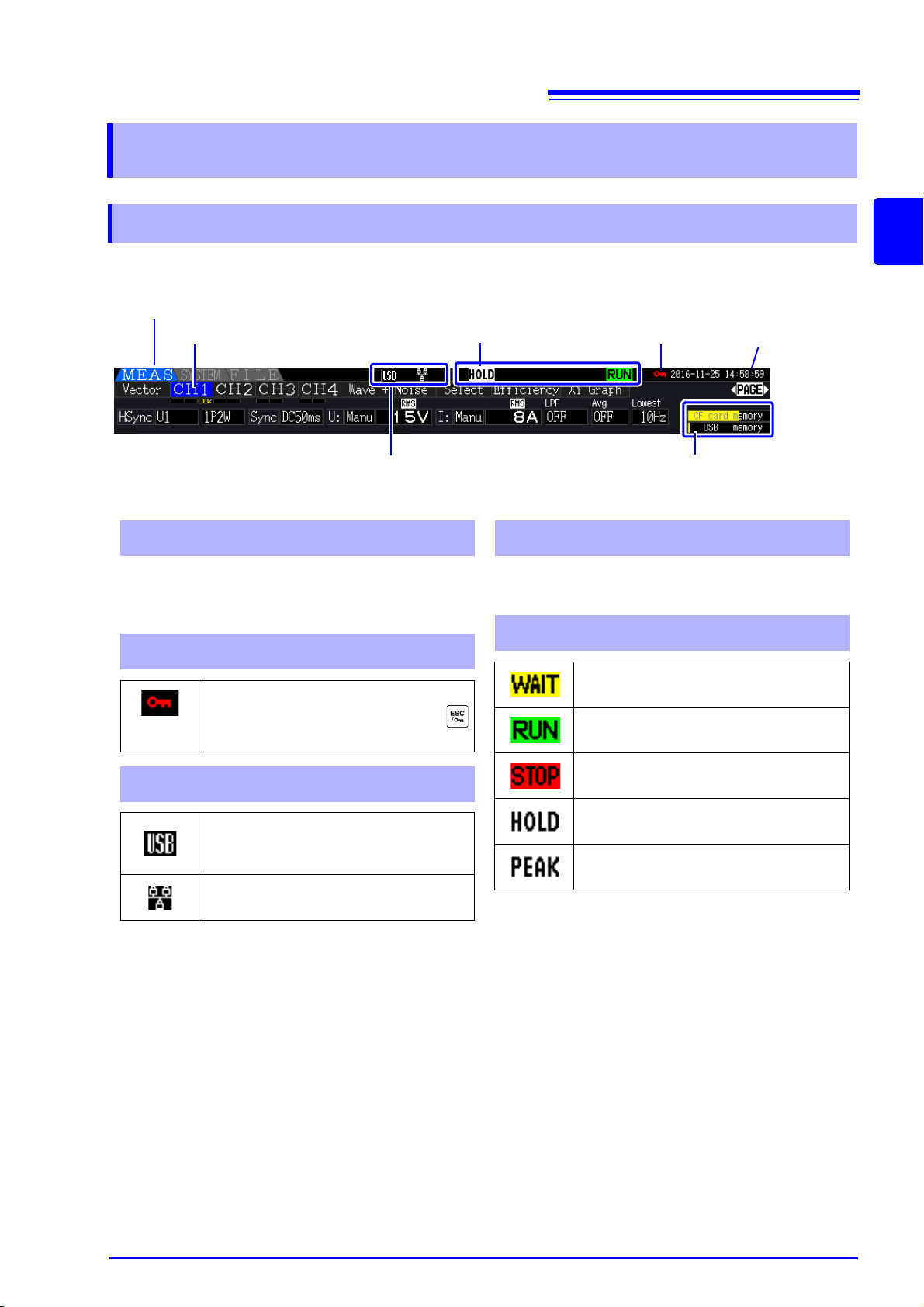
Operating State Indicators
45
Key-Lock Indicator
2
Displayed Page
Interface Indicators
Storage Media
Indicators
3
Displayed Screen
Time Display
Level indicators for the CF card and USB memory
stick. The used storage space is indicated in yellow, and it turns to red when the media is 95% full.
1 Storage Media Indicators
2 Key-Lock Indicator
Lights to indicate Key Lock is active
(keys are locked), after holding the
key for three seconds.
3 Interface Indicators
Lights when the instrument is connected to a computer by USB cable
(and the computer is on).
Lights when the instrument is connected to a LAN.
Displays the current date and time.
To set the Clock: (p. 129)
4 Time Display
5 Operating State Indicators
Indicates that the instrument is in the
integration standby state.
Indicates integration is in progress.
Indicates integration is stopped.
Indicates Data Hold is active.
Indicates Peak Hold is active.
1
2.3 Display Items and Screen Types
19
2.3.1 Common Display Items
These items are displayed on every screen.
2
Chapter 2 Names and Functions of Parts, Basic Operations & Screens
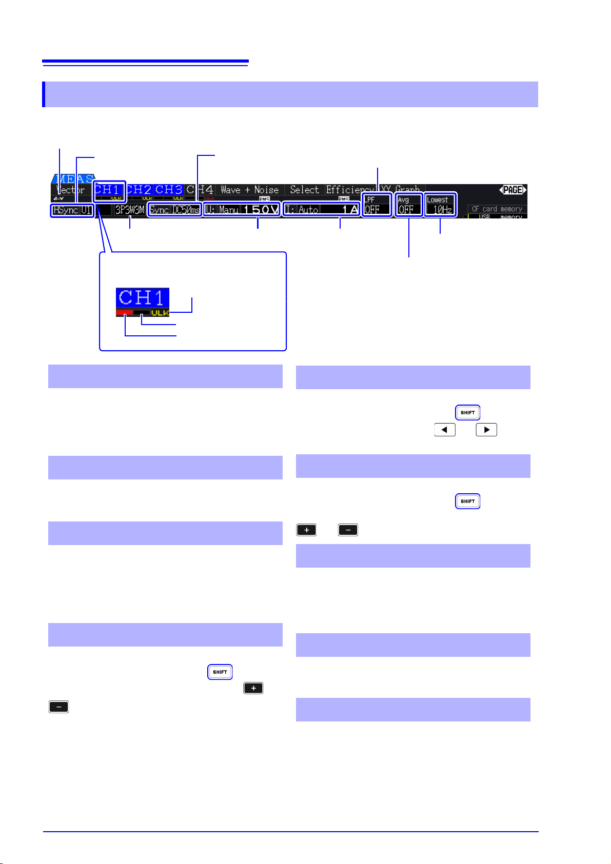
20
Current peak over range
Voltage peak over range
Sync Unlocked
Peak Over display indicators
1
Wiring mode
2
Voltage range
3
Current range
3
Average
5
Low-pass filter
4
Lower
measurement limit
6
Sync source
7
Harmonic sync
source
8
-Y Transform
9
These indicators appear in red at the bottom of
each channel page tab (CH1 to CH4). These indicate (from the left) when voltage and current peaks
ranges are exceeded (p. 48), and when synchronization is unlocked (p. 57).
Indicates the selected wiring mode (p. 34). The wiring mode (phase system selection) must be set to
match actual measurement connections.
• Indicate the voltage and current range settings.
• The settings are made by the RANGE keys (p. 52).
• When the range has been set manually, [MANU]
appears.
• When the auto-ranging is enabled, [AUTO]
appears (p. 51).
Indicates the low-pass filter setting (p. 62).
To change the setting, hold the key while
pressing an
LPF key (one of the left-most or
RANGE keys).
1 Peak Over display indicators
2 Wiring mode
3 Voltage range/Current range
4 Low-pass filter
Indicates the averaging setting state (p. 110).
To change the setting, hold the key while
pressing the
AVG key either or of the
PAGE key.
Displays the lower measurement limit setting (p. 58).
To change the setting, hold the key while
pressing a
LOW FREQ key (one of the right-most
or
RANGE keys).
Indicates the synchronization source signal that
determines the period (between zero crossings)
used as the basis for all calculations.(p. 56) The setting is made on the Input Settings page of the Settings screen.
Indicates the synchronization signal source used for
harmonic measurements.(p. 77) The setting is made
on the Input Settings page of the Settings screen.
Indicates whether -Y transform is enabled or disabled (ON/OFF)(p. 116). The setting is made on the
Input Settings page of the Settings screen.
5 Average
6 Lower measurement limit
7 Sync source
8 Harmonic sync source
9 -Y Transform
2.3 Display Items and Screen Types
2.3.2 Measurement Screen
These display items appear only on the Measurement screen.
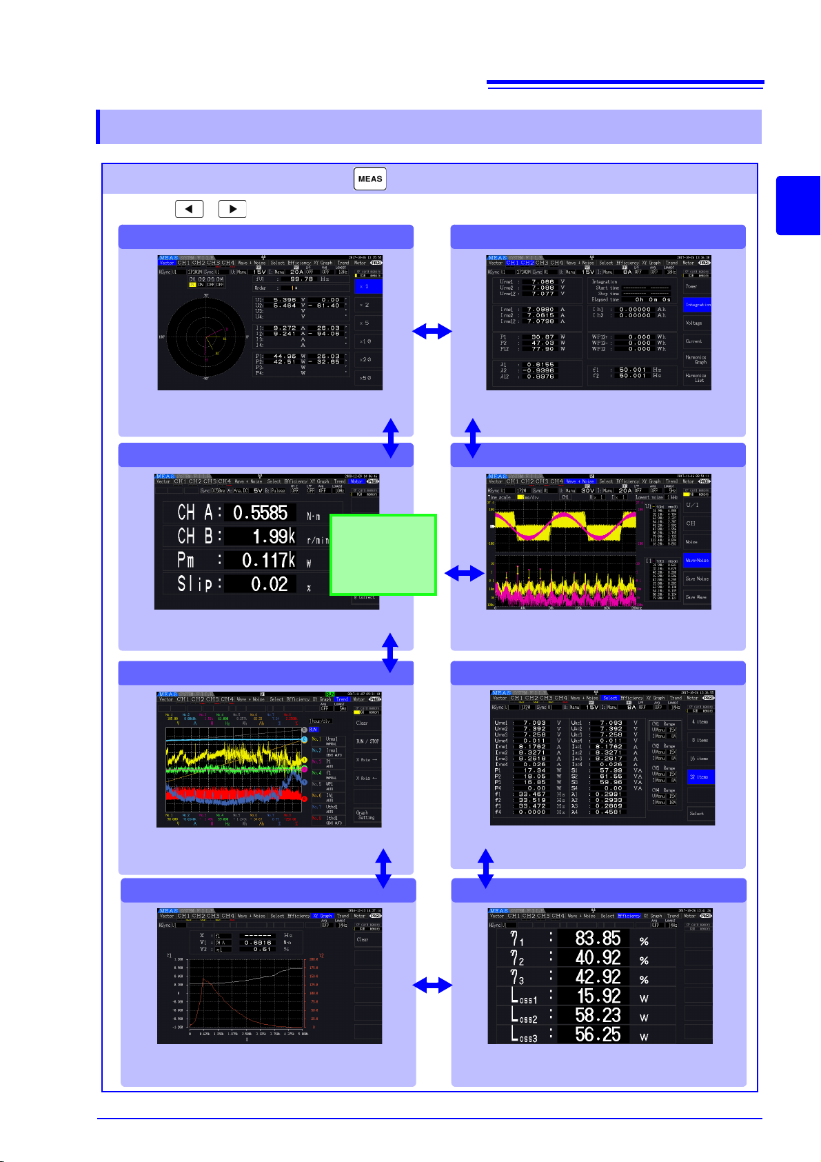
2.3.3 Screen Types
[Efficiency]
This page displays the numerical values of efficiency
and loss determined by calculation formulas.
[XY Graph]
This page displays an X-Y graph of measurement
parameters selected for horizontal and vertical axes.
[CH1 to CH4]
[Motor]
[Trend]
[Wave + Noise]
[Vector]
[Select]
Measurement Screen (Press the key to display)
Press the keys to change the screen page as follows.
This screen displays measurement values.
This page displays measured harmonic voltage,
harmonic current, and harmonic power on channels
1 to 4 as numerical values and as vectors.
This page displays measured values for the
motor analysis.
This page displays measurement item fluctuations.
This page displays measured power, voltage and current
values, integration values, and provides access to
harmonic graphs and lists for each channel.
This page displays voltage, current, and noise
waveforms. The data can be saved.
Select any parameter on this page for display.
Displayed only on
the PW3390-03
(model with motor
analysis and D/A
output).
21
2.3 Display Items and Screen Types
2
Chapter 2 Names and Functions of Parts, Basic Operations & Screens
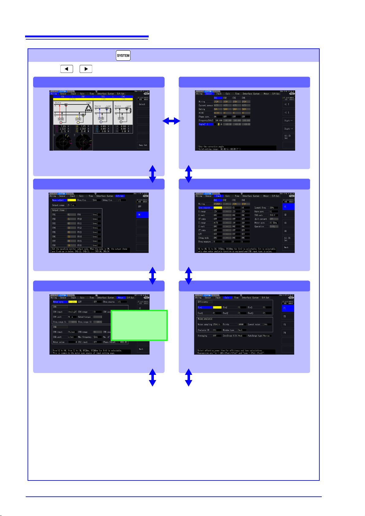
22
[Motor]
[Wiring]
[D/A Out]
Select the appropriate wiring mode (phase system configurations) and execute quick setup on this page. Wiring diagrams for each mode depict the appropriate
measurement cable connections.
Make D/A output-related settings on this page.
Make motor measurement-related settings
on this page.
[Sensor]
[Input]
Make detailed measurement criteria settings
on this page.
[Calc]
Make calculation-related settings on this page.
Setting Screen (Press the key to display)
Press the keys to change the screen page as follows.
Use this screen to view and change settings for measurement criteria,
wiring mode, wiring check and system environment configuration.
To next page
Displayed only on the
PW3390-03 (model
with motor analysis
and D/A output).
2.3 Display Items and Screen Types
 Loading...