

Hioki PW3390 Instruction Manual

EN
Communication Command Instruction Manual
PW3390
Power Analyzer
This instruction manual handles only parts related to commands.
For communication settings, please refer to the instruction manual for the main unit
Care has been taken to ensure the accuracy of the contents in this instruction
May.2018 Revised edition 1
PW3390A975-01 18-05H
manual, however, please approach HIOKI’s Sales Planning Division or your
nearest HIOKI dealer should you have any queries or found any mistakes.
Improvements may be made to this instruction manual without prior notice.
Unauthorized reproduction or copying of this instruction manual is prohibited.

PW3390 Power Analyzer Communication Command Instruction Manual Second Edition
1. Communication Command Overview ...................................................................................... 6
Commands/Messages ............................................................................................................................ 6
Command Syntax .................................................................................................................................. 7
Command Program Header .................................................................................................................. 7
Query Program Header ......................................................................................................................... 8
Response Message ................................................................................................................................. 8
Terminator and Separator .................................................................................................................... 9
Multiple-Command Header Omission ............................................................................................... 10
Note ...................................................................................................................................................... 10
2. Command Reference (Standard Command) .......................................................................... 11
Clear Standard Event Status Register (SESR) (except Output Queue) ......................................... 11
Read Standard Event Status Register (SESR) ................................................................................. 11
Query Device ID (Recognition Code) ................................................................................................. 12
Set 1 for Output Queue When Finished All Pending Operations .................................................... 12
Query Instrument Options ................................................................................................................. 13
Initialize Instrument .......................................................................................................................... 13
Request a Sampling ............................................................................................................................ 13
Execute Next Command after Command Has Finished Processing ............................................... 14
3. Command Reference (Device-Specific Commands) ............................................................ 15
Set and Query Frequency Full Scale ................................................................................................. 15
Set and Query Coefficient of Integrated Full Scale .......................................................................... 15
Set and Query D/A Output Items ....................................................................................................... 16
Select and Query Waveform Output .................................................................................................. 16
Setting and Querying Full-scale D/A Output Waveform .................................................................. 17
Select and Query Auto Range Limit .................................................................................................. 17
Set and Query Average ....................................................................................................................... 18
Set and Query LCD Backlight ............................................................................................................ 18
Select and Query Beep Sound ............................................................................................................ 19
Set and Query Efficiency, Pin of Loss Calculation Formula ............................................................ 19
Set and Query Efficiency, Pout of Loss Calculation Formula .......................................................... 20
Set and Query Automatic Saving ....................................................................................................... 20
Query Existence of CF Card ............................................................................................................... 21
Acquire File Name in CF Card ........................................................................................................... 21
Acquire Folder Name in CF Card ...................................................................................................... 22
Acquire File Data in CF Card ............................................................................................................ 23
Querying File Size in CF Card ........................................................................................................... 24
Set and Query Time ............................................................................................................................ 25
Set and Query Current Auto Range ................................................................................................... 26
Setting and Querying Phase Correction Formulas for Current Sensors ........................................ 26
2/107

PW3390 Power Analyzer Communication Command Instruction Manual Second Edition
Set and Query Phase Correction Angle for Current Sensors ........................................................... 27
Set and Query Phase Correction Frequency for Current Sensors ................................................... 27
Select and Query Current Rectifier Type .......................................................................................... 28
Set and Query Current Range ............................................................................................................ 29
Set and Query Current Sensor for CT9920 ....................................................................................... 30
Initialize Data of Saved Items ............................................................................................................ 30
Set and Query Efficiency, Saved Items of Loss Calculation Value .................................................. 31
Set and Query Saved Items of Motor Input ...................................................................................... 31
Initialize Harmonic Saved Data Items .............................................................................................. 32
Select and Query Harmonic List Saved Items .................................................................................. 33
Set and Query Output Order of Harmonic Data Saving .................................................................. 34
Set and Query Saved Items of Integration Values ........................................................................... 35
Set and Query Noise Peak Value Saving ........................................................................................... 36
Set and Query Saved Items of Normal Measurement Values in Respective Channels ................. 37
Set and Query Saved Items of SUM’s Normal Measurement Values ............................................. 38
Set and Query Saved Items of Voltage Data ..................................................................................... 39
Set and Query Saved Items of Current Data .................................................................................... 40
Select and Query ON/OFF of Δ-Y Calculation .................................................................................. 41
Execute and Query Zero Adjust ......................................................................................................... 42
Key Operations of The Instrument .................................................................................................... 43
Switching Display ............................................................................................................................... 43
Setting and Querying Display Items of Select Screens .................................................................... 44
Select and Query Display Screen Color ............................................................................................. 44
Select and Query Start Up Screen ..................................................................................................... 45
Set and Query Motor Analysis Function Phase Zero Adjust Degree ............................................... 45
Select and Query Motor Analysis Function Channel A Input .......................................................... 46
Set and Query Motor Analysis Function Channel A Input Frequency Range ................................ 47
Set and Query Motor Analysis Function Channel A Rating Torque ................................................ 48
Select and Query Low-pass Filter of Motor Analysis Function ....................................................... 48
Execute and Clear Motor Analysis Function’s Phase Zero Adjust................................................... 49
Set and Query Motor Analysis Function Channel A Range ............................................................. 49
Set and Query Motor Analysis Function Channel A Scaling ........................................................... 50
Set and Query Input Frequency Source for Motor Analysis Function’s Slip Calculation ............. 50
Set and Query Motor Analysis Function’s Motor Synchronized Sources ........................................ 51
Select and Query Motor Analysis Function Channel A Unit ........................................................... 51
Execute Zero Adjust of Motor Analysis Function .............................................................................. 52
Set and Query Motor Analysis Function Channel B Range ............................................................. 52
Set and Query Pulse ON/OFF of Motor Analysis Function Channel B Input ................................ 53
Set and Query Motor Analysis Function Channel Z Input .............................................................. 53
Set and Query Motor Analysis Function Channel B Measured Maximum Frequency ................. 54
3/107

PW3390 Power Analyzer Communication Command Instruction Manual Second Edition
Set and Query Motor Analysis Function Motor Pole Value ............................................................. 54
Set and Query Pulse Values of Motor Analysis Function Channel B .............................................. 55
Set and Query Motor Analysis Function Channel B Scaling ........................................................... 55
Select and Query Motor Analysis Function Channel B Units ......................................................... 56
Select and Query Noise Analysis Measurement Channel ................................................................ 56
Set and Query Noise Lower Limit Frequency ................................................................................... 57
Select and Query Noise Analysis Point Values ................................................................................. 57
Select and Query Noise Analysis Sampling Speed ........................................................................... 58
Set and Query Noise Analysis Window Function ............................................................................. 58
Set and Query Zero Cross Filter ........................................................................................................ 59
Set and Query Measurement Lower Limit Frequency ..................................................................... 59
Select and Query Frequency Measurement Source .......................................................................... 60
Select and Query Harmonic Synchronized Source ........................................................................... 60
Set and Query THD Calculation Formula......................................................................................... 61
Set and Query Header for Response Message .................................................................................. 61
Set and Query Hold Status ................................................................................................................. 62
Set and Query Integration Mode ....................................................................................................... 63
Execute Integration Data Reset ......................................................................................................... 63
Execute Integration (Time) Start ....................................................................................................... 64
Query Integration (Time) .................................................................................................................... 64
Execute Integration (Time) Stop ........................................................................................................ 64
Set and Query Interval Time.............................................................................................................. 65
Set and Query IP Address .................................................................................................................. 65
Set and Query Default Gateway ........................................................................................................ 66
Set and Query Subnet Mask .............................................................................................................. 66
Set and Query Key Lock ..................................................................................................................... 67
Set and Query Main Instrument Display Language ........................................................................ 67
Select and Query Low Pulse Filter (LPF) ......................................................................................... 68
Query Measurement Data .................................................................................................................. 69
Query Harmonic Measurement Data ................................................................................................ 70
Query Noise Measurement Value Data ............................................................................................. 71
Query Voltage Noise Measurement Value Data................................................................................ 71
Query Current Noise Measurement Value Data .............................................................................. 72
Initialize Communication Output Item Data.................................................................................... 72
Set and Query Efficiency, Loss Calculation Value Communication Output Items ........................ 73
Set and Query Communication Output Items of Motor Input ........................................................ 74
Initialize Harmonic Communication Output Data Items ................................................................ 74
Select and Query Harmonic List Communication Output Items .................................................... 75
Set and Query Output Order of Harmonic Data Communication Output ..................................... 76
Set and Query Communication Output Items of Integration Value ............................................... 77
4/107

PW3390 Power Analyzer Communication Command Instruction Manual Second Edition
Set and Query Normal Measurement Value Communication Output Items of Respective
Channels .............................................................................................................................................. 78
Set and Query SUM’s Normal Measurement Value Communication Output Items ..................... 79
Set and Query Voltage Data Communication Output Items ........................................................... 80
Set and Query Current Data Communication Output Items .......................................................... 81
Query Existence of USB Memory ...................................................................................................... 82
Acquire File Name in USB Memory .................................................................................................. 82
Acquire Folder Name in USB Memory .............................................................................................. 83
Acquire File Data in USB Memory .................................................................................................... 83
Querying File Size in USB Memory ................................................................................................... 84
Select and Query Wiring Mode .......................................................................................................... 85
Setting and Querying Formula for Three-phase Power ................................................................... 86
Set and Query Execution Confirmation Message ............................................................................. 86
Select and Query RS232C Communication Speed ............................................................................ 87
Set and Query Automatic Saving Folder Name ................................................................................ 87
Set and Query Manual Saving Folder Name .................................................................................... 88
Select and Query Manual Saving Media Location ........................................................................... 88
Setting and Querying Delimiter for CSV File ................................................................................... 89
Set and Query CT Ratio ...................................................................................................................... 89
Set and Query VT Ratio ...................................................................................................................... 90
Set and Query Synchronized Source .................................................................................................. 90
Select and Query Actual Time ON/OFF ............................................................................................ 91
Set and Query Actual Time Start Time ............................................................................................. 92
Set and Query Actual Time Stop Time .............................................................................................. 93
Select and Query Master/Slave of Synchronized Control Master ................................................... 94
Set and Query Synchronized Event Items ........................................................................................ 94
Set and Query Timer Control ON/OFF ............................................................................................. 95
Set and Query Timer ........................................................................................................................... 95
Set and Query Numerical Data Format ............................................................................................ 96
Set and Query Response Message Unit Separator ........................................................................... 97
Set and Query Voltage Auto Range .................................................................................................... 98
Select and Query Voltage Rectifier Type ........................................................................................... 99
Set and Query Voltage Range ........................................................................................................... 100
Set and Query Zero Suppress ........................................................................................................... 101
4. Fundamental Measurement Item Parameters ..................................................................... 102
5. Troubleshooting ..................................................................................................................... 107
5/107
PW3390 Power Analyzer Communication Command Instruction Manual Second Edition
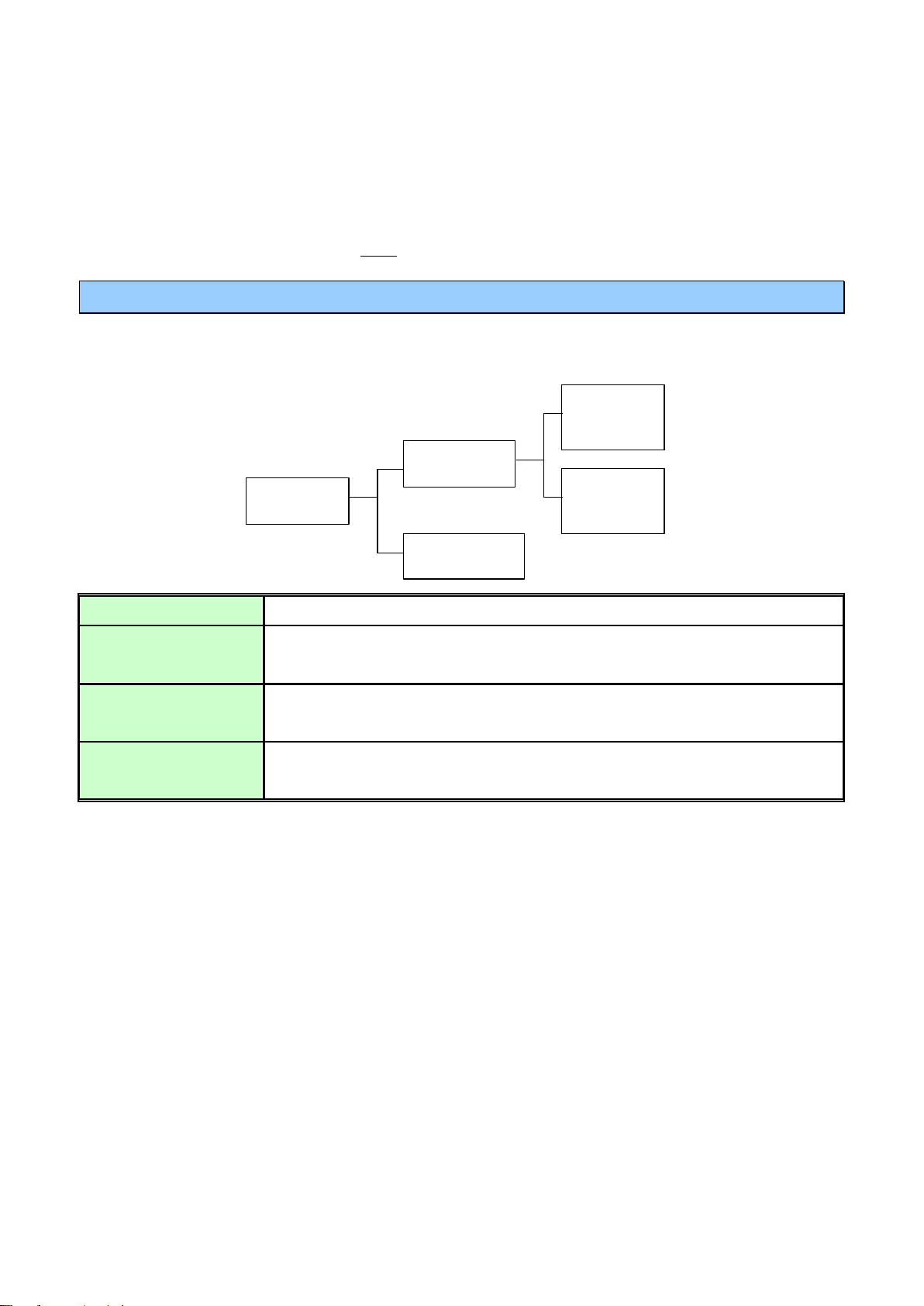
Message
Program
Message
Response
Message
Command
Program
Message
Query
Program
Message
Program Message
Message sent from the controller to the instrument.
Response Message
Message sent from the instrument to the controller. This message is created at
the time when a query program message is received and syntax checked.
Command Program
Message
Command to control settings and resetting of the instrument.
Query Program
Message
Order to interrogate instrument on operation results, measurement results,
and setting status.
1. Communication Command Overview
The PW3390 Power Analyzer can communicate with PC via LAN(TCP/IP) or RS-232C, so that users
can control the functions, and acquire measurement data and recorded data through text commands and
queries.
The port number of TCP/IP is fixed to 3390.
Commands/Messages
Data sent and received from the communication device are called messages and are classified as
follows.
Command/Program message, and Query Program Message are collectively known as commands.
6/107
PW3390 Power Analyzer Communication Command Instruction Manual Second Edition
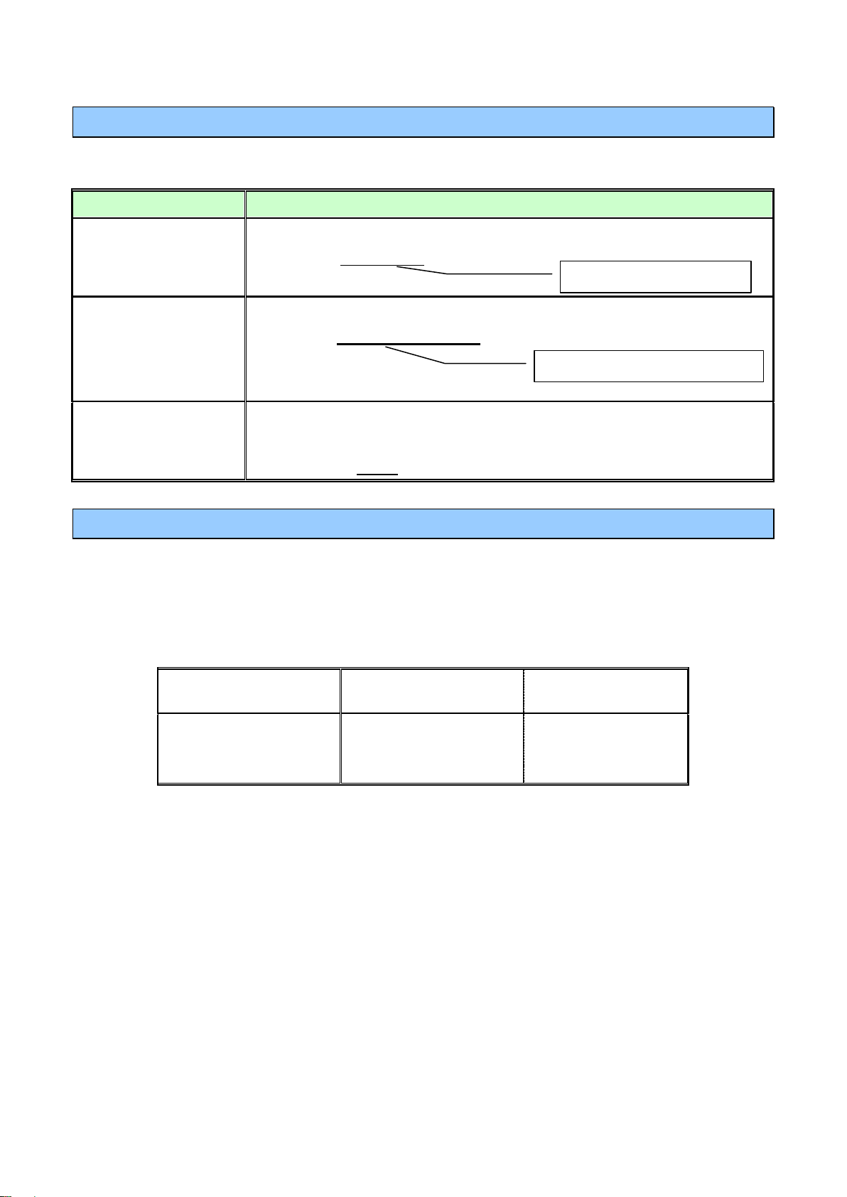
Description as shown in this manual
(Command Name)
Short Form
Long Form
DISPlay
DISP
DISPLAY
Types of Commands
Description
Explanation
Simple Command Type
A sequence of letters
[Example] :HEADer ON
Compound Command
Type
Multiple simple command type headers separated by colons ":"
[Example] :VOLTage1:RANGe 600
Standard Command
Type
Begins with an asterisk "*", indicating that it is a standard command defined
by IEEE 488.2.
[Example] *RST
Data
Simple Command Type
Data
Compound Command Type
Command Syntax
Commands are accepted in uppercase, lowercase or a mixture of both types of letters. Command
names are chosen to mnemonically represent their function, and can be abbreviated. The full command
name is called the "long form", and the abbreviated name is called the "short form". The command
references in this manual indicate the short form in uppercase letters, extended to the long form in lower
case letters.
The response message from the main device is returned as long form in uppercase letters.
Example
A mixture of uppercase and lowercase letters such as DiSpLay is accepted, but DISPLA, DISPL and DIS
are considered as errors.
Command Program Header
A header shows what kind of function that command has.
A command always requires a header and comes in three types, “Simple Command Type”, “Compound
Command Type”, and “Standard Command Type”.
7/107
PW3390 Power Analyzer Communication Command Instruction Manual Second Edition
Types of Commands
Description
Simple Command Type
A sequence of letters
[Example] :HEADer?
Compound Command
Type
Multiple simple command type headers separated by colons ":"
[Example] :VOLTage1:RANGe?
Standard Command
Type
Begins with an asterisk "*", indicating that it is a standard command defined
by IEEE 488.2.
[Example] *IDN?
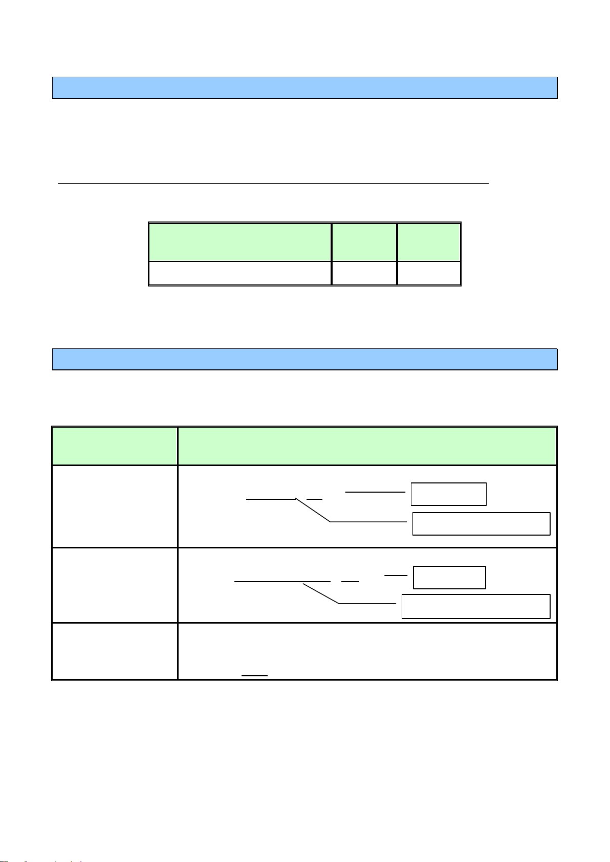
Query Program Message
:VOLTage1:RANGe?
Response Message
:VOLTAGE1:RANGE 300
300
(When header is ON)
(When header is OFF)
Simple Command Type
Compound Command Type
Query Program Header
These commands are used to interrogate the instrument about the results of operations and settings. A
query is formed by appending a question mark "?" after a program header
Response Message
The response message to a query, like the program message, consists of the header and data and is in
principle outputted in the same format as the program message in response to the query. The header
can be omitted.
[Example]
8/107
PW3390 Power Analyzer Communication Command Instruction Manual Second Edition
Main instrument/Communication
Software Setting
ANSI Word
code
(hexadecimal)
Meaning
English Name
CR+LF
0Dh 0Ah
Recovery +
Change line
Carriage Return + Line Feed
Message Unit Separator
Header Separator
Data Separator
Terminator and Separator (1) Message Terminator
The message terminator means the division of one message forwarding.
However, there is no message in the terminator.
(2) Message Unit Separator
The semicolon ";" is a message unit separator and is used to write multiple messages in one line.
[Example] :VOLTage1:RANGe 600;:CURRent:RANGe 50
(3) Header Separator
In a message containing header and data, a space (header separator) is used to separate the header
from the data.
[Example] :VOLTage1:RANGe 600
(4) Data Separator
In a message containing multiple data items, commas are used to separate the data items from one
another.
[Example] :AOUT:ITEM Urms1,Irms1,P1,Q1,S1,PF1
9/107

PW3390 Power Analyzer Communication Command Instruction Manual Second Edition
Multiple-Command Header Omission
When several commands having a common header are combined to form a compound command
if they are written together in sequence, the common portion can be omitted. This common portion is
called the "current path", and until it is cleared, the interpretation of subsequent commands presumes
that they share the same common portion.
This usage of the current path is shown in the following example:
Full Expression :VOLTage1:RANGe 600;:VOLTage1:MEAN OFF
Compacted Expression :VOLTage1:RANGe 600;MEAN OFF
The current path is cleared when the power is turned on, when reset by key input, by a colon ":" at the
start of a command, and when a message terminator is detected.
Standard command messages can be executed regardless of the current path. They have no effect
upon the current path.
A colon ":" is not required at the start of the header of a Simple or Compound command. However, to
avoid confusion with abbreviated forms and operating mistakes, we recommend always placing a colon
at the start of a header.
Note
Beeps when a communication error occurs if beep is enabled for this instrument.
Avoid inserting or removing storage media while using commands that refer to files and media.
10/107

PW3390 Power Analyzer Communication Command Instruction Manual Second Edition
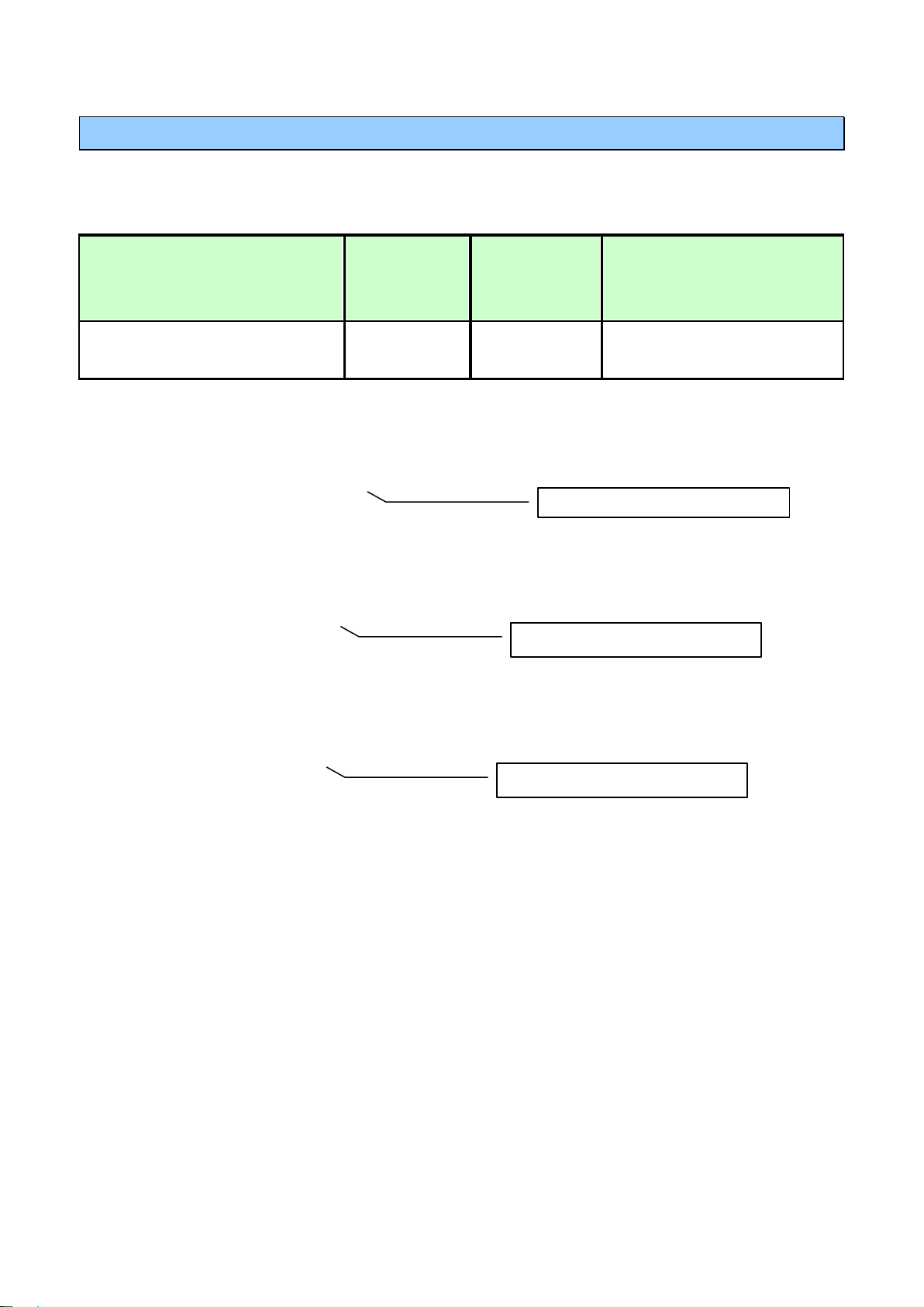
128
64
32
16 8 4 2 1
bit 7
bit 6
bit 5
bit 4
bit 3
bit 2
bit 1
bit 0
PON
URQ
CME
EXE
DDE
QYE
RQC
OPC
2. Command Reference (Standard Command)
Clear Standard Event Status Register (SESR) (except Output Queue)
Syntax Command *CLS
Example Clear Event Register. (SESR)
Note ・No effect on Output Cue.
Read Standard Event Status Register (SESR)
Syntax Query *ESR?
Example Return SESR Contents as NR1 numerical values 0-255.
PON: Power-On Flag. Set to 1 when the power is turned on, or upon recovery from an outage.
URQ:User Request. Unused.
CME:Command error. (The command to the message terminator is ignored.)
This bit is set to 1 when a received command contains a syntactic or semantic error:
• Program header error
• Incorrect number of data parameters
• Invalid parameter format
EXE: Execution Error
This bit is set to 1 when a received command cannot be executed for some reason.
• The specified data value is outside of the set range
• The specified setting data cannot be set (Invalid data format)
• Cannot be executed when another function is in operation (during hold, integration,
etc.)
DDE:Device-Dependent Error
This bit is set to 1 when a command cannot be executed due to some reason other
than a command error, a query error or an execution error.
• Execution is impossible due to an internal instrument fault
QYE:Query Error (the output queue is cleared)
This bit is set to "1" when an abnormality occurs in processing an output queue.
• When the data overflows the output queue
RQC: Controller privilege request. Unused
OPC: Operation Complete. Unused
Example Response *ESR 32 (when HEADER is ON)
32 (when HEADER is OFF)
11/107

PW3390 Power Analyzer Communication Command Instruction Manual Second Edition
Query Device ID (Recognition Code)
Syntax Query *IDN?
Example Query Instrument ID.
Response “Maker’s name”, “Model name”, “Serial number”, “Software version”
Description Response HIOKI,PW3390-03,081225345,V1.00
InstrumentID is HIOKI,PW3390-03,081225345, and software version is 1.00.
Note "*IDN?" is the last query message inside the program message.
Therefore, any subsequent query (in the same line) that is detected will lead to a query
error and no response message will be outputted.
Set 1 for Output Queue When Finished All Pending Operations
Syntax Query *OPC?
Description When the command (of transferred commands) prior to the *OPC command has
finished processing, “1” is stored in the output queue.
Response *OPC 1 (when HEADER is ON)
1 (when HEADER is OFF)
Example :DEMAG;*OPC?
:After DEMAG command has finished processing, 1 is stored in the output queue.
12/107

PW3390 Power Analyzer Communication Command Instruction Manual Second Edition
Query Instrument Options
Syntax Query *OPT?
Description Queries the types of options available in the instrument.
Response CH1 sensor, CH2 sensor, CH3 sensor, CH4 sensor
Example ACDC500, ACDC500, ACDC500, ACDC500
Note "*OPT?" is the last query message inside the program message.
Therefore, any subsequent query (in the same line) that is detected will lead to a query
error and no response message will be outputted.
Initialize Instrument
Syntax Command *RST
Description Initializes all instrument settings besides language and communication setting and returns
them to factory default.
Example *RST
Request a Sampling
Syntax Command *TRG
Description Performs one measurement when the display values or peak values are held.
Example :HOLD ON;*TRG;:MEAS?
13/107

PW3390 Power Analyzer Communication Command Instruction Manual Second Edition
Execute Next Command after Command Has Finished Processing
Syntax Command *WAI
Description Commands after *WAI will not be executed until the next update has finished.
The time required for updating is usually 50 ms.
Example :MEAS?;*WAI;:MEAS?
Data will be retrieved each time the display is updated.
Note Display data will not change even when a command is executed when peak values are
held.
14/107

PW3390 Power Analyzer Communication Command Instruction Manual Second Edition
3. Command Reference (Device-Specific Commands)
Set and Query Frequency Full Scale
Syntax Command :AOUT:FREQuency (Frequency Data)
Query :AOUT:FREQuency?
Response Frequency Data :100Hz/500Hz/1kHz/5kHz
Description Command Sets the maximum frequency of D/A output’s Frequency Full Scale and the
motor.
Query Sets the maximum frequency of D/A output’s Frequency Full Scale and
returns it as words.
Example Command :AOUT:FREQ 100Hz
Set the Frequency Full Scale of D/A output as 100Hz.
Query :AOUT:FREQ?
Response :AOUT:FREQUENCY 100Hz (when HEADER is ON)
100Hz (when HEADER is OFF)
Note The settings for the D/A output’s Frequency Full Scale and the motor measured maximum
frequency are the same.
Set and Query Coefficient of Integrated Full Scale
Syntax Command :AOUT:INTEGrate <Magnification data>
Query :AOUT:INTEGrate?
Response Magnification Data :1/10,1/2,1,5,10,50,100,500,1000,5000,10000
Description Command Sets the integration full scale coefficient of D/A Output.
Query Sets the integration full scale coefficient of D/A output and returns it as
words.
Example Command :AOUT:INTEG 1
Set the coefficient of the D/A integration full scale as 1.
Query :AOUT:INTEG?
Response :AOUT:INTEGRATE 1 (when HEADER is ON)
1 (when HEADER is OFF)
15/107

PW3390 Power Analyzer Communication Command Instruction Manual Second Edition
Set and Query D/A Output Items
Syntax Command :AOUT:ITEM “Item 1”, “Item 2”,.......,”Item 16”
Query :AOUT:ITEM?
Response “Item 1”, “Item 2”, “Item 3”,.......,”Item 15”, “Item 16”
“Item 1 – 16” = Basic measured item parameters (Refer to 4. Fundamental
Measurement Item Parameters)
Description Command Sets the D/A output item. Output items can be specified from 1 to 16.
Output items in the unspecified D/A channels will not be changed.
Query Sets the D/A output items and return them as words.
Example Command :AOUT:ITEM Urms1,Irms1,P1,Q1,S1,PF1
Set the D/A outputs from Channel 1 in sequence as Voltage CH1 RMs,
Current CH1 RMS, Effective Current CH1, Ineffective Current CH1, Apparent
Power CH1, and Power Factor Ch1.
Query :AOUT:ITEM?
Response :AOUT:ITEM
Urms1,Irms1,P1,Q1,S1,PF1,OFF,OFF,OFF,OFF,OFF,OFF
,OFF,OFF,OFF,OFF (when HEADER is ON)
Urms1,Irms1,P1,Q1,S1,PF1,OFF,OFF,OFF,OFF,OFF,OFF,OFF,OFF,OFF
,OFF (when HEADER is OFF) (when HEADER is OFF)
Select and Query Waveform Output
Syntax Command :AOUT:MONitor <ON/OFF>
Query :AOUT:MONitor?
Response ON : Waveform output ON
OFF : Waveform output OFF
Description Command Sets the Waveform output ON/OFF.
Query Returns the setting of the waveform output as ON or OFF.
Example Command :AOUT:MON ON
Set the Monitor output as ON.
Query :AOUT:MON?
Response :AOUT:MONITOR ON (when HEADER is ON)
ON (when HEADER is OFF)
16/107

PW3390 Power Analyzer Communication Command Instruction Manual Second Edition
Setting and Querying Full-scale D/A Output Waveform
Syntax Command :AOUT:MONitor:SCALe <1/2>
Query :AOUT:MONitor:SCALe?
Response 1 : ±1V f.s.
2 : ±2V f.s.
Description Command Sets full-scale of D/A waveform output.
Query Returns setting for full-scale of D/A waveform output as a numeric value.
Example Command :AOUT:MON:SCAL 1
Query :AOUT:MON:SCAL?
Response :AOUT:MONITOR:SCALE 1 (when HEADER is ON)
1 (when HEADER is OFF)
Select and Query Auto Range Limit
Syntax Command :AUTOrange <WIDE/NARROW>
Query :AUTOrange?
Response <WIDE/NARROW>
WIDE : Widen the auto range limit.
NARROW : Narrow the auto range limit.
Description Command Selects to widen or narrow the auto range limit.
Query Returns the auto range limit as words.
Example Command :AUTO WIDE
Widen the auto range limit.
Query :AUTO?
Response :AUTORANGE WIDE (when HEADER is ON)
WIDE (when HEADER is OFF)
17/107

PW3390 Power Analyzer Communication Command Instruction Manual Second Edition
Set and Query Average
Syntax Command :AVEraging:MODE <OFF/FAST/MID/SLOW/SLOW2/SLOW3>
Query :AVEraging:MODE?
Response <OFF/FAST/MID/SLOW/SLOW2/SLOW3>
Explanation Command Sets the average.
Query Returns the average setting as words.
Example Command :AVE:MODE FAST
Set the average to FAST.
Query :AVE:MODE?
Response :AVERAGING:MODE FAST (when HEADER is ON)
FAST (when HEADER is OFF)
Set and Query LCD Backlight
Syntax Command :BACKlight <ON/1min/5min/10min/30min/60min>
Query :BACKlight?
Response <ON/1min/5min/10min/30min/60min>
Description Command Sets the LCD Backlight.
Query Returns the LCD Backlight setting as words.
Example Command :BACK 30min
Set the LCD Backlight to turn off automatically 30 minutes later.
Query :BACK?
Response :BACKLIGHT 30min (when HEADER is ON)
30min (when HEADER is OFF)
18/107

PW3390 Power Analyzer Communication Command Instruction Manual Second Edition
Select and Query Beep Sound
Syntax Command :BEEPer <ON/OFF>
Query :BEEPer?
Response <ON/OFF>
Description Command Set the beep sound ON/OFF.
Query Returns the On/OFF beep sound setting as ON or OFF.
Example Command :BEEP ON
Set the beep sound ON.
Query :BEEP?
Response :BEEPER ON (when HEADER is ON)
ON (when HEADER is OFF)
Set and Query Efficiency, Pin of Loss Calculation Formula
Syntax Command :CALCulate[number]:PIN <P1/P2/P3/P4/P12/P34/P123/Pm>
Query :CALCulate[number]:PIN?
[number] ・・・・ 1,2,3
Response “P1/P2/P3/P4/P12/P34/P123/Pm”
Description Command Sets Efficiency, Pin of Loss Calculation Formula.
Query Returns the settings of efficiency, Pin of Loss Calculation Formula as words.
Example Command :CALC1:PIN P1
Set the Pin of the Calculation formula 1 as P1.
Query :CALC1:PIN?
Response :CALCULATE1:PIN P1 (when HEADER is ON)
P1 (when HEADER is OFF)
Note When P12/P34/P123 cannot be selected because of wiring settings, they cannot be specified.
Pm cannot be specified except when it can be selected during the implementation of the motor
analysis function.
19/107

PW3390 Power Analyzer Communication Command Instruction Manual Second Edition
Set and Query Efficiency, Pout of Loss Calculation Formula
Syntax Command :CALCulate[number]:POUT <P1/P2/P3/P4/P12/P34/P123/Pm>
Query :CALCulate[number]:POUT?
[number] ・・・・ 1,2,3
Response “P1/P2/P3/P4/P12/P34/P123/Pm”
Description Command Sets the items for Efficiency, Pout of Loss Calculation Formula.
Query Returns the setting items for Pout of Loss Calculation Formula as words.
Example Command :CALC1:POUT Pm
Set the Pout item of Calculation Formula 1 as Pm.
Query :CALC1:POUT?
Response :CALCULATE1:POUT Pm (when HEADER is ON)
Pm (when HEADER is OFF)
Note When P12/P34/P123 cannot be selected because of wiring settings, they cannot be specified.
Pm cannot be specified except when it can be selected during the implementation of the motor
analysis function.
Set and Query Automatic Saving
Syntax Command :CARD:AUTO:SAVE <ON/OFF>
Query :CARD:AUTO:SAVE?
Response <ON/OFF>
ON: Automatic Save on
OFF: Automatic Save off
Description Command Sets the automatic saving to the CF Card On or OFF
Query Returns the setting for the automatic saving to the CF Card as On or OFF.
Example Command :CARD:AUTO:SAVE ON
Set the automatic saving to the CF Card ON.
Query :CARD:AUTO:SAVE?
Response :CARD:AUTO:SAVE ON (when HEADER is ON)
ON (when HEADER is OFF)
20/107

PW3390 Power Analyzer Communication Command Instruction Manual Second Edition
Query Existence of CF Card
Syntax Query :CARD:EXISt?
Response <Y/N>
Y:CF Card Exist
N:CF Card Doesn’t exist
Description Query Returns the existence of the CF Card in the instrument with Y or N.
Example Query :CARD:EXIS?
Response :CARD:EXIST Y (when HEADER is ON)
Y (when HEADER is OFF)
Acquire File Name in CF Card
Syntax Query :CARD:FILEname? “Specified Folder Name”
“Specified Folder Name”
Acquire the file name under the specified folder name.
When omitted, acquire the file name under the root folder.
Response “File name”, “Byte count”, “File name”, “Byte count”…
The order of “File name”, “Byte count” will continue for as long as there are
files.
When there are no more files, the words “NO_FILE” will be returned.
Description Query Acquires the file name under the folder specified from the CF card.
Example Query :CARD:FILE? PW3390
Acquire and return the file name under the PW3390 folder from the CF card.
Response :CARD:FILENAME H3390001.BMP,44862,M3390000.CSV,578 (when
HEADER is ON)
3390001.BMP,44682,M3390000.CSV,578 (when HEADER is OFF)
Note Up to 90 files displayed from the start of the screen can be acquired.
When more than 90 files exist in the same folder, subsequent file names cannot be acquired.
21/107

PW3390 Power Analyzer Communication Command Instruction Manual Second Edition
Acquire Folder Name in CF Card
Syntax Query :CARD:FOLDername?
Response “Folder name”, “Folder name”, “Folder name”…
Folder names will continue for as long as there are folders.
When there are no more folders, the words “NO_FOLDER” will be
returned.
Description Query Acquires the folder name under the root of the CF card.
Example Query :CARD:FOLD?
Response :CARD:FOLDERNAME PW3390 (when HEADER is ON)
PW3390 (when HEADER is OFF))
Note Up to 215 folders displayed from the start of the screen can be acquired.
When more than 215 folders exist in the root, subsequent folder names cannot be acquired.
22/107

PW3390 Power Analyzer Communication Command Instruction Manual Second Edition
Acquire File Data in CF Card
Syntax Query :CARD:PICKout? “File name”, “Start position”, “Stop position”,
“Specified folder name”
Syntax Response “File name”, “Start position”, “Stop position”, “Specified folder name”
File name:File name to be forwarded
Start position:Specify the acquired start position in the file with byte count
Stop position:Specify the acquired stop position in the file with byte count
Specified Folder Name:Search for file name under the specified folder
When omitted, search for the file name under the root.
Description Query Reads the specified file name under the folder from the CF card from the
start position to the stop position, attach STX (02) to the start and ETX (03) to
the end of the data to be forwarded, and forward data.
Example Query :CARD:PICK? 02030100.CSV,1,1000,PW3390
Return the 1-100 byte data of the 02030100.CSV file under the PW3390
folder from the CF card.
Response STX(02)HIOKI PW3390・・・・・ETX(03)
Note Even when the header is set as ON, headers will not attach to Response data.
Specify “1” if the beginning of the file is made the start position.
STX/ETX is not a ASCII Code but (02)/(03) of the Binary Data.
It automatically shifts to the measurement screen.
23/107

PW3390 Power Analyzer Communication Command Instruction Manual Second Edition
Querying File Size in CF Card
Syntax Query :CARD:SIZE? <Specified File Name>,<Specified Folder Name>
Response <File size (Bytes)>
Description Query Returns the size of the specified file.
Example Query :CARD:SIZE? H3390000.BMP,PW3390
Response :CARD:SIZE 35124 (when HEADER is ON)
35124 (when HEADER is OFF))
Note File name can be specified with a maximum of 40 characters.
If folder name is omitted, a file name will be used from under the root folder.
During execution of file operation, it can take some time to get a response.
24/107

PW3390 Power Analyzer Communication Command Instruction Manual Second Edition
Set and Query Time
Syntax Command :CLOCk “Year Data”, “Month Data”, “Day Data”, “Hour Data”, “Minute
Data”, “Second Data”
Query :CLOCk?
Response “Year Data”, “Month Data”, “Day Data”, “Hour Data”, “Minute Data”, “Second
Data”
Year Data: 2000 - 2079 (can be set 00 – 79)
Month Data: 01- 12
Day Data: 01 - 31
Hour Data: 00 - 23
Minute Data: 00 - 59
Second Data: 0
Description Command Sets the time of the clock in the main instrument.
Query Returns the time setting of the main instrument as NRI numerical values.
Example Command :CLOC 17,12,25,12,30,0
Set as 2017 December 25th 12:30:0
Query :CLOC?
Response :CLOCK 2017,12,25,12,30,45 (when HEADER is ON)
2017,12,25,12,30,45 (when HEADER is OFF)
Note The instrument can interpret days of the month as well as leap years, so specifying an
improbable date will lead to an error.
Always set 0 for the second data.
25/107

PW3390 Power Analyzer Communication Command Instruction Manual Second Edition
Set and Query Current Auto Range
Syntax Command :CURRent[CH]:AUTO <ON/OFF>
Query :CURRent[CH]:AUTO?
[CH] ・・・・ 1,2,3,4
Response ON: Measure current with auto range.
OFF: Measure current with manual range.
Description Command Set the current auto range ON/OFF.
Query Returns the current auto range setting with ON or OFF.
Example Command :CURR1:AUTO ON
Set the auto range of the Current Channel 1 to ON.
Query :CURR1:AUTO?
Response :CURRENT1:AUTO ON (when HEADER is ON)
ON (when HEADER is OFF)
Note When the range is set with the :CURRent[CH]:RANGeCommand, the auto range of the
specified channel will be OFF.
By combining measurement lines (for above IP3W), the auto ranges of other channels which
are combined are also set.
Setting and Querying Phase Correction Formulas for Current Sensors
Syntax Command :CURRent[CH]:CORRect <ON/OFF>
Query :CURRent[CH]:CORRect?
[CH] ・・・・ 1,2,3,4
Response ON:Turns ON phase correction formulas for current sensors
OFF:Turns OFF phase correction formulas for current sensors
Description Command Sets phase correction formulas for current sensors. [CH]: 1 to 4.
Query Returns setting for phase correction formulas for current sensors in a string.
Example Command :CURR1:CORR ON
Query :CURR1:CORR?
Response :CURRENT1:CORRECT ON (when HEADER is ON)
ON (when HEADER is OFF)
26/107

PW3390 Power Analyzer Communication Command Instruction Manual Second Edition
Set and Query Phase Correction Angle for Current Sensors
Syntax Command :CURRent[CH]:DEGRee <Phase correction angle>
Query :CURRent[CH]:DEGRee?
[CH] ・・・・ 1,2,3,4
Response Phase correction angle (°)
-90.00 to +90.00
Description Command Sets phase correction angle for current sensors. [CH]: 1 to 4.
Query Returns setting for phase correction angle for current sensors in a string.
Example Command :CURR1:DEGR 90.00
Query :CURR1:DEGR?
Response :CURRENT1:DEGREE +90.00 (when HEADER is ON)
+90.00 (when HEADER is OFF)
Set and Query Phase Correction Frequency for Current Sensors
Syntax Command :CURRent[CH]:FREQuency <Correction frequency (kHz)>
Query :CURRent[CH]:FREQuency?
[CH] ・・・・ 1,2,3,4
Response Correction frequency (kHz)
000.001 to 999.999
Description Command Sets phase correction frequency for current sensors. [CH]: 1 to 4.
Query Returns setting for phase correction frequency for current sensors in a string.
Example Command :CURR1:FREQ 200.000
Query :CURR1:FREQ?
Response :CURRENT1:FREQUENCY 200.000 (when HEADER is ON)
200.000 (when HEADER is OFF)
27/107

PW3390 Power Analyzer Communication Command Instruction Manual Second Edition
Select and Query Current Rectifier Type
Syntax Command :CURRent[CH]:MEAN <ON/OFF>
Query :CURRent[CH]:MEAN?
[CH] ・・・・ 1,2,3,4
Response ON: Set the current rectifier type to MEAN.
OFF: Set the current rectifier type to RMS.
Description Command Select the RMS/MEAN of the current rectifier type.
Query Returns the selection of the RMS/MEAN of the rectifier type as ON (MEAN)
or OFF (RMS).
Example Command :CURR1:MEAN OFF
Select the current rectifier type of Current Channel 1 as RMS.
Query :CURR1:MEAN?
Response :CURRENT1:MEAN OFF (when HEADER is ON)
OFF (WHEN HEADER IS OFF)
Note By combining measurement lines (for above IP3W), the current rectifier types of other channels
which are combined are also set.
28/107

PW3390 Power Analyzer Communication Command Instruction Manual Second Edition
Set and Query Current Range
Syntax Command :CURRent[CH]:RANGe <Current Range(NR2)>
Query :CURRent[CH]:RANGe?
[CH] ・・・・ 1,2,3,4
Response 0.1/0.2/0.4/0.5/0.8/1/2/4/5/8/10/20/40/50/80/
100/200/400/500/800/1000/2000/4000/8000/20000
Description Command Specifies the current range suitable for the sensor. (Unit is [A])
Query Queries the current range setting. Returns the current range as a numerical
value in NR2 format.
Example Command :CURR1:RANG 1.0
Set the current Channel 1 to 1A range.
Query :CURR1:RANG?
Response :CURRENT1:RANGE 1.0 (WHEN HEADER IS ON)
1.0 (WHEN HEADER IS OFF)
Note • Do not add a unit to the measurement range.
• Wait until the internal circuit has stabilized after changing a range before reading
measurements.
• When the range is specified, the auto range of the specified channel will be OFF.
• By combining measurement lines (for above IP3W), the settings for the current ranges of
other channels which are combined are also changed.
29/107

PW3390 Power Analyzer Communication Command Instruction Manual Second Edition
Set and Query Current Sensor for CT9920
Syntax Command :CURRent[CH]:TYPE <Current sensor>
Query :CURRent[CH]:TYPE?
[CH] ・・・・ 1,2,3,4
Response 100uV/A,1mV/A,10mV/A,100mV/A,
CT7642,CT7742,CT7044,CT7045,CT7046
Description Command Specifies current sensor for CT9920.
Query Queries the current sensor setting. Returns the current sensor as a character
string.
Example Command :CURR1:TYPE CT7642
Set the current sensor 1 to CT7642.
Query :CURR1:TYPE?
Response :CURRENT1:TYPE CT7642 (WHEN HEADER IS ON)
CT7642 (WHEN HEADER IS OFF)
Note • By combining measurement lines (for above IP3W), the current sensor of other channels
which are combined are also changed.
Initialize Data of Saved Items
Syntax Command :DATAout:ITEM:ALLClear
Description Command Initializes the saved data items.
Returns the saved data items to factory defaults.
Example Command :DATA:ITEM:ALLC
Initialize the saved data items.
30/107
 Loading...