

Hioki PW3365-20 Measurement Manual
PW3365-20
CLAMP ON POWER LOGGER
Measurement Guide
Apr. 2018 Revised edition 1 Printed in Japan
PW3365A984-01 18-04H
Thank you for purchasing the HIOKI PW3365-20
Clamp On Power Logger.
This guide introduces the PW3365-20's basic
measurement procedure with the Quick Set to
rst time users.
Before using the instrument, be sure
to read the Instruction manual carefully.
EN
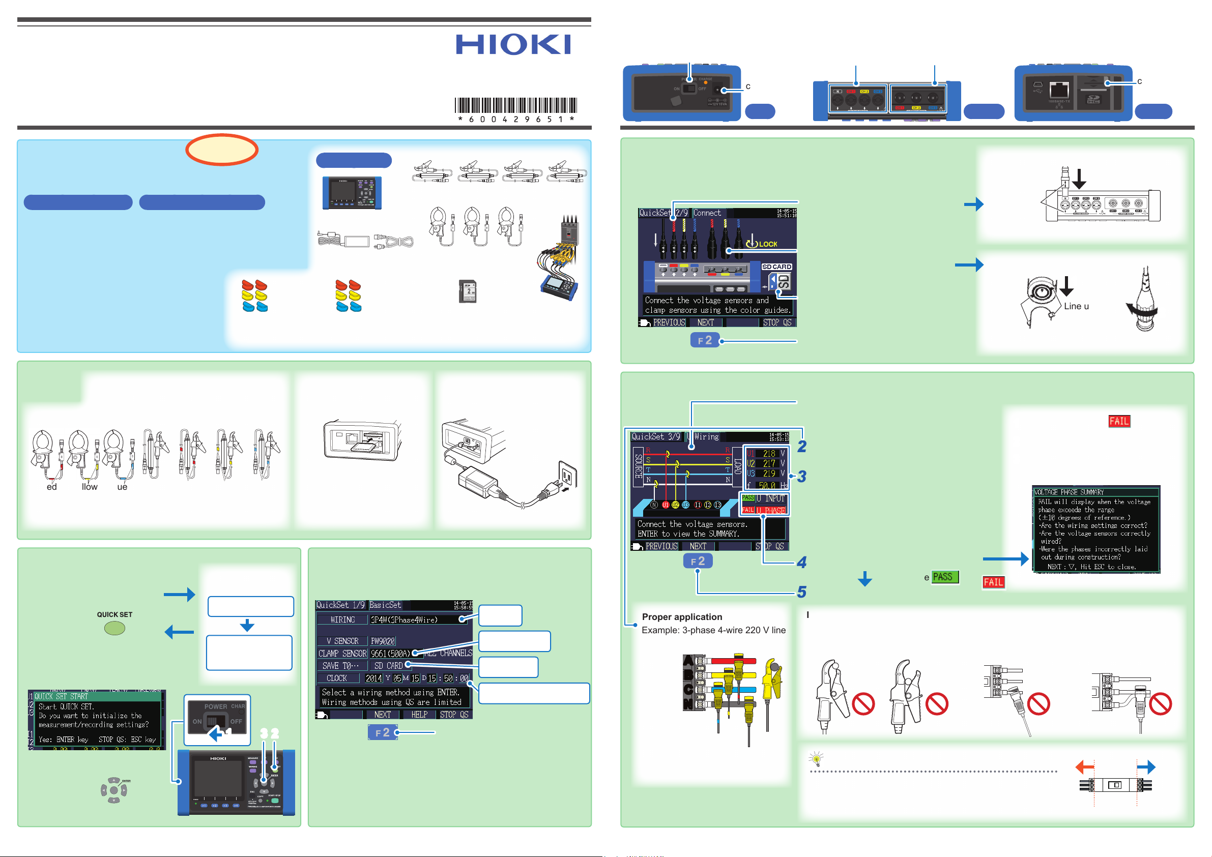
Names of Parts (excerpt)
POWER Switch
AC adapter
connection jack
Left Upper
Voltage sensor input terminals
(Connect voltage sensors.)
Current sensor input terminals
(Connect clamp sensors.)
SD memory
card slot
Right
Easy conguration with the Set
How to congure electric energy measurement for a
3-phase 4-wire 220 V line
Setting Items Setting Example
Wiring : 3P4W (3-phase 4-wire)
Clamp sensor : Model 9661 (500 A rating)
Current range : 50 A
Save to... : SD memory card
Save interval : 5 minutes
Save items : Average only
Folder/Filename : Automatic
Rec. start method : Interval
Rec. stop method : Manual
Clock setting : User-specied
Measurement frequency : 50 Hz
Preparations
(CH1) (CH2) (CH1) (CH2)(N)
Red
Yellow Red YellowNone
Model 9661 Model PW9020
Attach the color clips.
1
(CH3)
Blue
Quick
Red (CH1)
Yellow (CH2)
Blue (CH3) Blue (CH3)
Color clips for clamp
sensors
(CH3)
Blue
1. Starting the Quick Set
First time powered
Turn on the instrument.
1
(
on left side of instrument
Press the key.
2
The Quick Set Start dialog will
be displayed.
on only
)
Language setting
Measurement
frequency setting
(50 Hz)
231
Press the Enter
3
key.
You will need
Model PW3365-20
Model Z1008 AC Adapter
Red (CH1)
Yellow (CH2)
Color clips for
voltage sensors
Insert the SD memory
2
card. (on right side of
instrument)
Be sure to provide a Hioki
optional SD Memory Card.
Operation is not guaranteed
with other SD memory cards.
2. Basic settings
Model PW9020 Safety Voltage Sensor x4
Model 9661 Clamp on
Sensor (optional) x 3
SD memory card
(optional)
Connect the AC adapter.
3
(
on left side of instrument
Congure settings as
1
shown in screenshot
below.
3P4W
9661 (500 A)
SD CARD
Set the current time.
Press the F2 [NEXT] key.
2
Concept image
of measurement
3-phase 4-wire
220 V line
3. Connect the sensors to the instrument.
Match the color of each sensor’s color clip to the color
of the terminal.
Connect the voltage sensors
1
to the voltage sensor input
terminals.
Connect the clamp sensors
2
to the current sensor input
terminals.
Be sure that the SD memory
3
card is inserted. (on right
side of instrument)
Press the F2 [NEXT] key.
4
Clamp sensor connector (BNC)
Line up
Voltage sensor connector
Insert
Align
Voltage sensor input terminals
Insert
1
Line up
Current sensor
input terminals
2
Lock the
connector.
4. Connecting voltage sensors to the measurement target
)
Proper application
Example: 3-phase 4-wire 220 V line
Secondary side of breaker
Secondary
side
(Load side)
OK
Align the insulated wire with the
marks on the voltage sensor to
the wire.
For more information, see “3.6 Connecting
the Voltage Sensors to Target to be
Measured” in the instruction manual.
A
B
C
N
Yellow
Blue
Red
None
Refer to the wiring diagram to check
1
the locations to which you have
connected the voltage sensors.
Connect the voltage sensors to the
2
secondary side of the breaker.
Check the readings.
3
In this example, the screen should indicate
approximately 220 V and 50 Hz if there is
no problem.
(Because the measurement target is a 220
V line, and the frequency being measured
is 50 Hz.)
Verify the results of checking the
4
wiring.
Press the F2 [NEXT] key.
5
Improper application Failure to apply the sensor properly will prevent you from being to
Clamped with the
tips of the clip
All results are .
make an accurate measurement.
Clamped too far
back in the clip
If there is a
Clamped with the
measurement target at an
angle
Move the cursor to item.
1
Press the
2
Check the contents of the dialog box
3
and correct the wiring.
result
Primary side
key.
Enter
Clamping targets with
different voltages at the
same time
Secondary side
Tip
The power source side of the breaker is called the primary
side; whereas the load side, the secondary side.
For your safety, connect the voltage sensors and the clamp
sensors to the secondary side.
Source side
Breaker
Load side
A
B
C
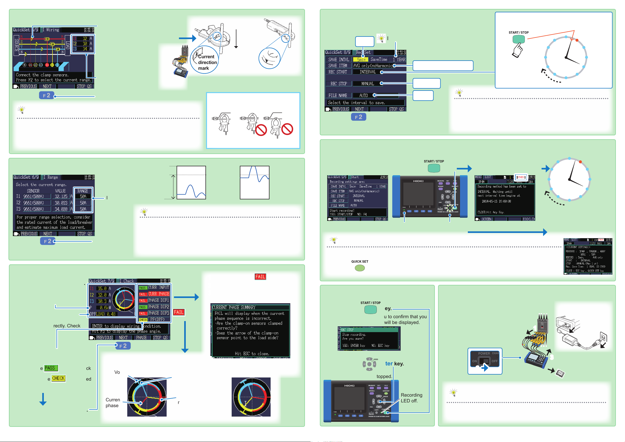
5. Connecting clamp sensors to the measurement target
Refer to the wiring diagram
1
to check the locations to
which you have connected
the clamp sensors.
Connect the clamp
2
sensors to the secondary
side of the breaker.
Verify that measured
3
values are being displayed.
Current
direction
mark
Power source
side
Load side
Point the arrow
toward the load
side.
When using 9660 sensor
8. Recording settings
Congure settings as shown in screenshot below.
1
5 min
Is this value shorter than the measurement interval?
(
SaveTime
by the free space of the SD memory card
and save items. Up to 1 year)
AVG only (no Harmonic)
MANUAL
: It’s calculated automatically
Rec. start method: INTERVAL
Example: With the save interval set to 5 min.
Start
12
11
10
9
8
7
recording
1
2
3
4
5
6
Recording
Recording
Recording
Recording
Recording
Press the F2 [NEXT] key.
4
Tip
When the measured value is shown as 0 A
The zero-display processing* (which forces the display to read “0 A” when the reading is
0.4% of the range) may cause the display to read “0 A.” Try lowering the current range
while referring to “11.6 Range Conguration and Accuracy by Clamp Sensor” in the
instruction manual.
6. Setting the current range
*Example: For the 500 A range, values that are less than or equal to
2 A (0.4% of 500 A) will be displayed as 0 A.
Display range
Effective
measurement
range
Set the range.
1
In this example
the instrument
is set to 50 A.
Press the F2
2
[NEXT]
key.
(Guaranteed
accuracy
,
range)
50 A range 10 A range
Tip
Set the current range based on the anticipated maximum load current that will
occur during the measurement period. (Refer to the operating status, load rating,
breaker rating, and other data to make this determination.) If the range is too low,
the instrument will experience an over-range event during measurement, making
accurate measurement impossible. If the range is too high, a large error component
will result, making accurate measurement impossible.
Reference
Clamp 1 conductor only.
OK
PROHIBITED
65 A (130% f.s.)
Over-range
55 A (110% f.s.)
0 A 0 A
13 A (130% f.s.)
11 A (110% f.s.)
AUTO
Press the F2 [NEXT] key.
2
9. Checking settings and starting recording
For more information, see “Chapter 6 Starting and Stopping Recording
and Measurement” in the instruction manual.
Check the settings.
1
Press the key.
2
POWER LED
Recording LED
ashing (standby)
Tip
If the
SaveTime
methods can be used to increase the available save time:
• Increase the
• If there is any unnecessary data on the SD memory card, delete it or
reformat the card. (Exit the Quick Set and access the File screen.)
The standby screen will be
shown. Pressing any key will
display the Measurement screen.
(Standby state continues.)
is shorter than the measurement period, the following
SAVE INTVL
.
Recording will start at a well-dened
time.
Data will be saved to the SD
memory card for each save interval.
Tip
• The auto power-off function will cause the screen to turn off, but recording will continue (the Recording and
Power LEDs will stay on).
Start recording
12
11
10
9
8
7
Recording LED lit up
(recording)
1
2
3
4
5
6
Recording
Recording
Recording
Recording
Recording
7. Checking the clamp sensor (current) wiring
Check measured values.
1
• Is the value low or negative?
Verify that the instrument has been
wired (connected) correctly.
• Is the value low? If the value is
lower than 0.5, the instrument
may be wired incorrectly. Check
the wiring.
Verify the results of
2
checking the wiring.
If all results are
the wiring because
but nd no problems.
Press the F2 [NEXT] key.
3
or if you check
,
is displayed
Check even if the graph display falls within
the pass range.
Voltage phase PASS range
Current
phase
Fail result Pass result
1
2
3
If there is a
result
Voltage phase
Current phase PASS
range
Move the cursor to item.
Press the
Check the contents of the dialog box and
correct the wiring.
Enter
key.
• Press the
and setting information on a single screen.
key to display the Setting Conrmation screen, which allows you to check key recording
10. Stopping recording
Press the key.
1
A dialog box asking you to conrm that you
wish to stop recording will be displayed.
Press the Enter key.
2
Recording will be stopped.
Recording
LED off.
After measurement is complete
Disconnect the
Disconnect the sensors from
1
the measurement target.
Turn off the instrument.
2
Disconnect the sensors
3
from the instrument.
1
4
AC adapter.
3
Remove the SD
2
Tip
Saved data can be loaded onto a computer and analyzed using the
SF1001 Power Logger Viewer (optional) or an application such as
Spreadsheet software.
For more information, see “9.3 SF1001 Power Logger
Viewer (Optional)” in the instruction manual.
5
memory card.
(on left side of
instrument)
 Loading...