

Hioki PW3360-20, PW3360-21 Measurement Manual

PW3360-20, PW3360-21
CLAMP ON POWER LOGGER
Measurement Guide
Nov. 2017 Revised edition 3 Printed in Japan
PW3360A984-03 17-11H
Thank you for purchasing the HIOKI PW3360
Clamp on Power Logger.
This guide introduces the PW3360's basic measurement procedure with the Quick Set to firsttime users.
Before using the instrument, be sure to read
the Instruction manual carefully.
EN
<You will need>
Model PW3360
Clamp on Power Logger
Color Clips
Yellow (CH2)
Red (CH1)
Yellow (CH2)
Black (N)
Model L9438-53 Voltage Cords
Blue (CH3)
Blue (CH3)
Model 9661 Clamp on Sensor
(optional) x 3
Easy configuration with the Quick Set
How to configure electric energy measurement
for a 3-phase, 4-wire 220 V line
Setting Example Value
Wiring: 3P4W (3 phase, 4 wire)
Clamp sensor: Model 9661 (500 A rating)
Current range: 50 A
Save to...: SD memory card
Save interval: 5 minutes
Save items: PW3360-20 Average only
PW3360-21 Average only (no harmonics)
Filename: Automatic
Rec. start method: Interval
Rec. stop method: Manual
Clock setting: User-specified
Measurement frequency:50 Hz
Model Z4001
SD Memory
Card 2GB
(optional)
Model Z1006 AC Adapter
Concept image of measurement
3-phase, 4-wire 220 V line
Red (CH1)
Getting reading
Be sure to provide a Hioki optional
SD memory card.
Operation is not guaranteed with other
SD memory cards.
For CH2For CH1
2
Insert the SD memory card.
3
Connect the AC adapter.
For CH3
Attach the color clips.
1
Model 9661 Model 9661 Model 9661
Red
clip
Yellow
clip
Blue
clip
1 Starting the Quick Set
2 Basic settings
9661 (500A)
3P4W
SD card
Set the current time.
Language setting
Measurement
frequency setting
1
(50 Hz)
First power-on only
3
Press the “Enter” key.
Turn on the instrument.
The Quick Set Start dialog
will be displayed.
2
Press the key.
3
2
See: Instruction manual
“1.3 Names and Functions
of Parts”
1
Configure the settings as the following screen, and then
press the "NEXT" key.
2
3 Peripheral connections
Proper way to connect a BNC connector
When disconnecting the BNC connector, be sure to
release the lock before pulling off the connector.
Forcibly pulling the connector without releasing the
lock, or pulling on the cable, can damage the connector.
1
3
Insert the voltage cord connectors.
Be sure that the SD memory card is inserted.
1
Line up the
connector.
2
Connect the clamp sensors.
4
Press the "Next" key.
Color cilps
Align terminals and colors.
1
2
3
4
See: Instruction manual
“1.3 Names and Functions
of Parts”
BNC connector
Lock the
connector.
Line up
BNC connector
Current input
terminal
Example
3-phase, 4-wire 220 V line
Secondary side of breaker
When clipping connectors the
wiring bar, clip them to the
metallic portion of the bar.
2
Check the readings.
In this example, the readings
should be approximately
220 V and 50 Hz.
1
Check the wiring diagram.
3
4
Verify the results of
checking the wiring.
Move the cursor to item.
Press the “Enter” key.
Check key points and correct the wiring.
1
2
3
All results are
To avoid electric shock and short circuits, do not
allow the voltage cord clips to touch two wires at the
same time. Never touch the edge of the metal clips.
4 Connecting voltage cords to the measurement line
5
Press the “Next” key.
Result is
See: Instruction manual
“Chapter 3 Configuration and Measurement”
1
3
4
5
Breaker
Source
Load
Secondary side
For your safety, connect
the voltage cords and the
clamp sensors to this side.
Primary side
What are the primary and secondary sides of
the breaker?
The power source side of the breaker is called
the primary side; whereas the load side, the
secondary side.
OK
Connect the voltage
cords to the secondary side of the breaker.
CA B N
Hint
2
Red Yellow Blue Black
PROHIBITED
-1- -2-
5 Connecting the clamp sensors to the measurement lines
When the measured value is shown as 0 A
The zero-display processing (which forces the display to
read “0 A” when the reading is 0.4% of the range) may
cause the display to read “0 A.” Try using a lower current
range as described in the following step.
See: Instruction manual “2.6 Turning the Power On/Off”
1
Check the wiring
diagram.
When using 9660 sensor
Clamp 1 conductor only.
Hint
Example: Zero-display processing
With the 500 A range
Display will read “0 A” when the measured
value is 2 A (0.4% of 500 A) or less.
3
Verify that
measured values
are being displayed.
Point the arrow toward the load side.
OK
3
1
4
4
Press the
“Next” key.
2
Connect the clamp
sensors to the secondary side of the
breaker.
Power supply side
Load side
Current
direction
mark
2
Apply the clamps to the
measurement lines.
PROHIBITED
Move the cursor to item.
Press the “Enter” key.
Check key points and correct the wiring.
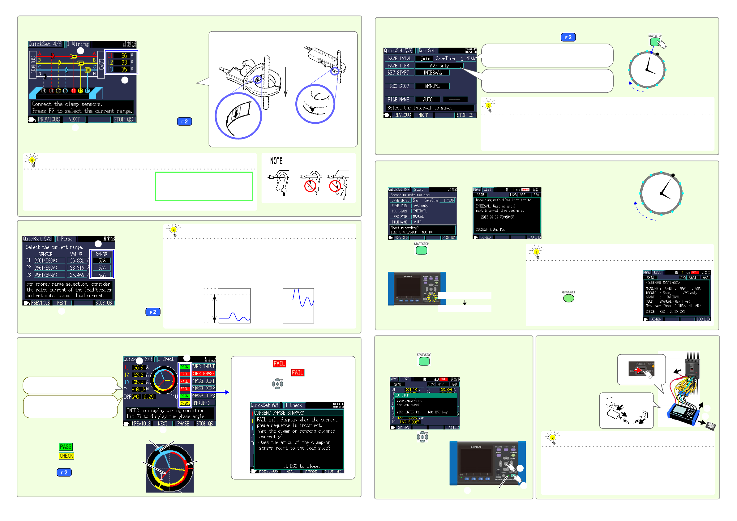
6 Setting the current range
Select an appropriate range based on factors such as the rated load, operating state, and breaker rating. When the range is too low, an over-range event
will occur during measurement, preventing accurate measurement. When the
range is too high, the magnitude of the error component will increase, preventing accurate measurement. Set the current range based on your expectation
of the maximum load current that will flow during the measurement period.
7 Checking the clamp sensor (current) wiring
Hint
2
Verify the results of checking the
wiring.
If a result is
1
2
3
Is the value low? If the value is lower
than 0.5, the instrument may be
wired incorrectly. Check the wiring.
55 A (110% f.s.) 11 A (110% f.s.)
0A 0A
50 A range 10 A range
Over-range
Is the value negative?
Check the wiring.
1
Check measured values.
Example
If all results are , or if you check the
wiring because is displayed but
find no problems
1
Set the range.
Effective measurement range
(Guaranteed accu-
racy range)
65 A (130% f.s.)
Display range
13 A (130% f.s.)
In this example,
the instrument is
set to 50 A.
Voltage phase
Voltage phase
Current phase
Current phase
PASS range
PASS range
2
Press the
“Next” key.
3
Press the “Next” key.
1
2
3
1
2
If the available save time is shorter than the measurement period, the following methods can
be used to increase the available save time:
• Increase the save interval.
• If there is any unnecessary data on the SD memory card, delete it or reformat the card.
(Exit the Quick Set and access the File screen.)
Hint
1
2
3
4
5
6
7
8
9
10
11
12
With the save interval
set to 5 min.
Recording
Recording
Recording
Start recording
Recording
Recording
Verify that the value is longer than the period for
which you wish to perform measurement.
(The maximum data storage time is one year.)
PW3360-20 Average only
PW3360-21 Average only (no harmonics)
Rec. start method:
Interval time
Example
8 Recording settings
Configure the settings as the following screen, and then press the "NEXT" key.
9 Checking settings and starting recording
• The auto power-off function will cause the
screen to turn off, but recording will continue (the Recording and Power LEDs will
stay on).
• Press the key to display the Setting
Confirmation screen, which allows you to
check key recording and setting information on a single screen.
If you wish to close the window,
press any key. The standby state
will continue.
Hint
Data will be saved to the SD
card for each save interval.
Check the settings.
1
Press the key.
The instrument will enter the standby state.
Recording will start at a well-defined time.
2
1
2
3
4
5
6
7
8
9
10
11
12
Recording
Recording
Start recording
Recording
Recording
Recording
See: Instruction manual
“Chapter 6 Starting and Stopping
Recording and Measurement”
Recording LED flashing
Recording LED on
Stand by for recording.
10 Stopping recording
Saved data can be loaded onto a computer and analyzed using the
SF1001 Power Logger Viewer (optional) or an application such as
Spreadsheet software. For more information, see the instruction
manual. (Harmonic data is saved in a binary format and can only be
analyzed by the SF101 Power Logger Viewer.)
See: Instruction manual “9.2 SF1001SF1001 Power Logger Viewer
(Optional)”
Hint
Disconnect the wires.
1
Turn off the instrument.
2
11 After measurement is complete
Disconnect the cables
from the instrument.
3
Remove the SD
memory card.
5
4
Disconnect the
AC adapter.
Press the key.
The Rec Stop dialog will be displayed.
1
Press the “Enter” key.
Recording LED off
1
2
3
2
2
4
5
3
1
-3- -4-
 Loading...