

Hioki PW3360-20, PW3360-21 Instruction Manual

Instruction Manual
PW3360-20
PW3360-21
CLAMP ON POWER LOGGER
May 2014 Revised edition 3 PW3360A981-03 14-05H


Contents
Contents
i
1
Introduction ..............................................................................1
Confirming Package Contents................................................2
Safety Information....................................................................4
Operating Precautions.............................................................7
Measurement Flowchart ..........................................................9
Chapter 1
Overview__________________________________11
1.1 Product Overview ....................................................11
1.2 Features ....................................................................12
1.3 Names and Functions of Parts ...............................14
1.4 Screen Configuration ..............................................17
1.5 On-Screen Indicators ..............................................19
Chapter 2
Measurement Preparations___________________ 21
2.1 Preparation Flowchart ................... ..........................21
2.2 Preparing to Use the Instrument after Purchase ..22
Bundle the Voltage Cord Leads with the Spiral Tubes .....22
Wrapping Color-coded Spiral Tubes around Clamp
Sensors and Grouping Together Cables ..........................23
Installing (replacing) the Battery Pack ..............................24
Storing the Instrument in the C1005 Carrying Case
(Option) ............................................................................27
Setting the Language and Measurement Line Frequency
(50/60 Hz) ........................................................................28
2.3 Pre-Operation Inspection ........................................29
2.4 Inserting (Removing) an SD Memory Card ...........30
2.5 Supplying the Power ...............................................33
Connecting the AC Adapter .............................................33
Supplying Power from Measurement Lines
(Using the PW9003 Voltage Line Power Adapter) ...........35
2.6 Turning the Power On/Off .......................................38
2

ii
Contents
Chapter 3
Connecting to Lines to be Measured ___________41
3.1 Connection Procedure .......... .. ............................... 42
3.2 Setting Measurement Conditions on the Wiring
Diagram Screen ...................................................... 43
3.3 Connecting the Voltage Cords ............ ... .. ... ... .. ..... 47
3.4 Connecting a Clamp Sensors ................................ 49
3.5 Connecting the Voltage Cords to Lines to be
Measured ................................................................. 51
3.6 Connecting Clamp Sensors to Lines to be
Measured ................................................................. 52
Load Current Measurement .............................................52
Leakage Current Measurement ................................... ....53
3.7 Setting the Current Range ..................................... 54
3.8 Verifying Correct Wiring (Wiring Check) .............. 56
Chapter 4
Changing Settings __________________________61
4.1 Viewing and Using the Settings Screen ............... 62
4.2 Changing Measurement Settings .......................... 63
Measurement 1 Setting Screen .......................................63
Measurement 2 Setting Screen .......................................65
4.3 Changing Recording (Save) Settings ................... 69
Recording 1 Setting Screen .............................................69
Recording 2 Setting Screen .............................................74
4.4 Changing System Settings (as Necessary) .......... 77
System 1 Setting Screen .................................................77
System 2 Setting Screen .................................................79
4.5 Initializing the Instrument (System Reset) ........... 80
Reverting the Instrument to Its Factory Settings
(Factory Reset) ................................................................81
4.6 Factory Settings ...................................................... 82

Chapter 5
Viewing Measurement Data __________________ 83
5.1 Viewing and Using the Measurement Screen .......83
1P2W x 2 or 1P2W x 3 Wiring ..........................................84
5.2 List of Measurement Screens .................................85
5.3 Viewing Data (Voltage, Current, Power, and Energy)
as a List ....................................................................86
5.4 Viewing Voltage and Current Value Details
(RMS Values, Fundamental Wave Values, Peak
Values, and Phase Angles) .....................................87
5.5 Viewing Power Details (Channel Power Values) ..88
5.6 Viewing Energy
(Active Energy and Reactive Energy) ....................89
5.7 Viewing a Demand Graph .......................................90
5.8 Viewing a Harmonic Graph (PW3360-21 only) ......91
5.9 Viewing a Harmonic List (PW3360-21 only) ..........93
5.10 Viewing Waveforms .................................................95
Changing the Zoom Factor for the Vertical Axis Used to
Display Voltage and Current Waveforms .........................96
5.11 Enlarging Measured Values on the Display ..........97
5.12 Viewing a Trend Graph ...........................................98
iii
Contents
3
4
5
6
Chapter 6
Starting and Stopping Recording and
Measurement _____________________________101
6.1 Starting Recording ................................................102
Starting Recording Manually ..........................................102
Staring Recording by Specifying a Time ........................103
Starting Recording at a Good Time Division
(Interval Time) ................................................................104
6.2 Stopping Recording ..............................................105
Stopping Recording Manually ........................................105
Stopping Recording by Specifying a Time .....................105
6.3 Using Repeat Recording .......................................106
6.4 Operation When a Power Outage Occurs While
Recording .......................... .......................... ........... 108

iv
Contents
Chapter 7
Quick Set_________________________________109
7.1 Settings Configured with the Quick Set ........ .. ... 109
7.2 Settings That Can Be Added to Quick Set
Settings ........................... ............. .......... ............. ... 110
Chapter 8
Saving Data and Manipulating Files __________113
8.1 Viewing and Using the File Screen ..................... 114
8.2 Folder and File Structure ..................................... 116
SD Memory Card ...........................................................116
Internal Memory .............................................................120
8.3 Saving Copies of the Screen
(SD Memory Card Only) ....................................... 121
8.4 Saving Settings Files ............................................ 122
8.5 Loading Settings Files .................................... ..... 123
SD Memory Card ...........................................................123
Internal Memory .............................................................124
8.6 Copying Internal Memory Files to the SD
Memory Card .......................... ............................... 125
8.7 Deleting Folders and Files ................................... 126
8.8 Formatting the SD Memory Card or Internal
Memory ............................. ..................................... 127
Chapter 9
Analyzing Data on a Computer_______________129
9.1 Copying Data to a Computer (SD) ....................... 130
9.2 SF1001 Power Logger Viewer (Optional) ............ 132
9.3 Checking Recording and Measurement Data
with Excel .............................................................. 134
Opening recording and measurement data ...................134
Saving Data as an Excel File .........................................135
Example of Data from a Measurement File ...................136
Measurement File Contents ...........................................136
Converting Measured Value Exponential Data ..............144

Contents
Appendix
v
9.4 Using the PW3360/PW3365 Auto Excel Graph
Creation Application ..................................... .. ... ...145
Chapter 10Using Communications (USB/LAN)__ 147
10.1 Copying Data to a Computer (USB) .....................148
10.2 Installing the USB Driver on a Computer ............150
10.3 Installing the PW3360/PW3365 Settings and
Download Application (USB/LAN) .......................150
10.4 Using the PW3360/PW3365 Settings and
Download Application (USB) ................................151
Initiating USB Communications between the PW3360
and a Computer .............................................................151
Disconnecting the USB connection from the Computer .154
10.5 LAN Communications ...........................................155
Configure the Instruments LAN Settings ........................156
Connecting the Instrument and Computer with a
LAN Cable ......................................................................158
10.6 Using the PW3360/PW3365 Settings and
Download Application (LAN) ................................161
Initiating LAN Communications between the PW3360
and a Computer .............................................................161
Disconnecting the LAN connection from the Computer .16 2
10.7 Remote Control of the Instrument by Internet
Browser ..................................................................163
Operating the Instrument Remotely ...............................165
Setting a Password ........................................................166
If You Forget Your Password .........................................166
Chapter 11
Using Pulse Input and Output _______________ 167
11.1 Connecting Wires to the Pulse I/O Terminals .....168
11.2 Configuring Pulse Settings ..................................169
11.3 Inputting a Pulse Signal ........................... .. ...........170
Signal Input Method .......................................................170
11.4 Outputting a Pulse Signal .......................... ... .. ......172
Index
7
8
9
10
11
12
13

vi
Contents
Chapter 12
Specifications_____________________________175
12.1 General Specifications ......................................... 175
12.2 Basic Specifications ............................................. 178
12.3 Detailed Measurement Specifications ................ 182
12.4 Functional Specifications .................................... 190
12.5 Calculation Formulas . ... ....................................... 201
12.6 Range Configuration and Accuracy by Clamp
Sensor ............................. .......... ........... ....... ........... 210
When the 9660, 9661, or 9695-03 is Used ....................211
When the 9669 is Used ..................................................211
When the 9694 or 9695-02 is used (CAT III, 300 V) ......212
When the CT9667 is Used .............................................212
12.7 Model PW9003 Voltage Line Power Adapter ...... 213
Chapter 13
Maintenance and Service ___________________215
13.1 Trouble Shooting .................................................. 215
Before Having the Instrument Repaired .........................217
13.2 Cleaning .......................... .......... ........... .......... ........ 219
13.3 Error Indication ................................ ... .................. 219
13.4 Disposing of the Instrument ................................ 224
Appendix____________________________________A1
Appendix1 How the Instrument Samples Data.................A1
Appendix2 Three-phase 3-wire Measurement..................A2
Appendix3 Method for Calculating Active Power
Accuracy...........................................................A5
Appendix4 Terminology .....................................................A6
Index___________________________________Index 1
Introduction
Thank you for purchasing the HIOKI Model PW3360 Clamp on
Power Logger.To obtain maximum performance from the instrument, please read this manual first, and keep it handy for future reference.
Registered trademarks
• Microsoft and Windows are either registered trademarks or
trademarks of Microsoft Corporation in the United States and
other countries.
• Microsoft and Excel are either regi
marks of Microsoft Corporation in the United States and other
countries.
•
The SD logo is a trademark of SD-3C, LLC.
Model Numbers
In this Instruction Manual, “PW3360” is used as the instrument
model.
1
Introduction
stered trademarks or trade-
Model No.
PW3360-10 Not available
PW3360-11 Available
PW3360-20 Not available
PW3360-21 Available
PW3360-30 Not available
PW3360-31 Available
Harmonic measurement
function
Operation panel
Japanese
English
Chinese
2
Confirming Package Contents
Confirming Package Contents
• When you receive the instrument, inspect it carefully to ensure that no damage
occurred during shipping. In particular, check the accessories, panel keys, and
connectors. If damage is evident, or if it fails to operate according to the specifications, contact your authorized Hioki dist
ributor or re
• Use the original packing materials when transporting the instrument, if possible.
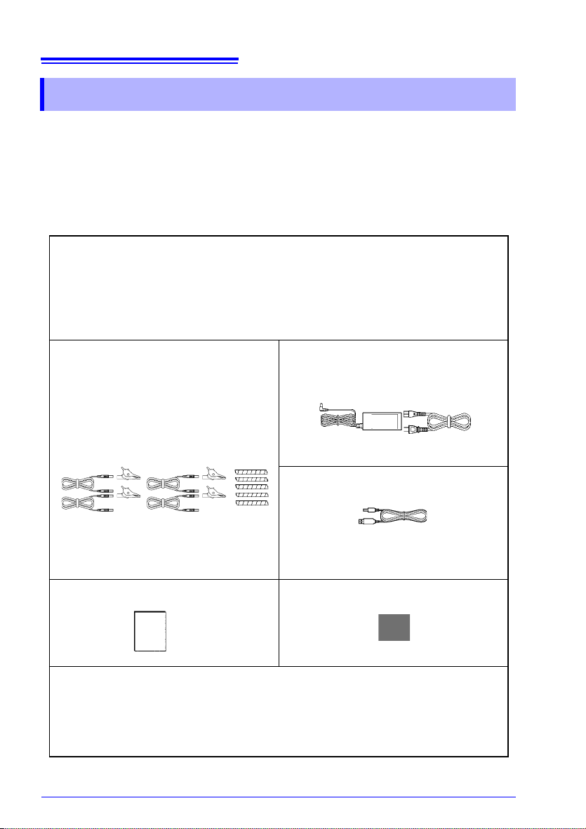
Check that the package contents are correct.
Model PW3360 Clamp on Power Logger ................1
seller.
Model L9438-53 Voltage Cord
..............................................1 Set
Alligator Clip.........................4
(red, yellow, blue, and black /one each)
Banana - banana leads........ 4
(red, yellow, blue, and black /one each)
Spiral tubes..........................
(for band
See: "Bundle the Voltage Cord Leads with
ing the cords)
the S
piral Tubes" (p. 22)
3.3, "Connecting the Voltage Cords" (p.
47)
Instruction Manual
5
.......... 1 Measurement Guide....... 1
Model Z1006 AC Adapter
(includes power cord)......1
USB Cable
......................1
Spiral Tubes for the clamp sensors ......................................... 1 set
For color-coding purposes (red, yellow, and blue/2 each)
For banding the cords (Black)
See: "Wrapping Color-coded Spiral Tubes around Clamp Sensors and Grouping Together
Cables" (p. 23)
........................................................5
.............6

3
Confirming Package Contents
Options
The following options are provided for the PW3360. For purchase, contact your
authorized Hioki distributor or reseller.
For current measurement
Model 9660 Clamp on Sensor (100 Arms rated)
Model 9661 Clamp on Sensor (500 Arms rated)
Model 9669 Clamp on Sensor (1000 Arms rated)
Model 9694 Clamp on Sensor (5 Arms rated)
Model 9695-02 Clamp on Sensor (50 Arms rated)
Model 9695-03 Clamp on Sensor (100 Arms rated)
Model 9219 Connection Cable (For use with Model 9695-02/9695-03)
Model CT9667 Flexible Clamp on Sensor (5000 A rms rated)
Model 9657-10 Clamp on Leak Sensor
Model 9675 Clamp on Leak Sensor
Model 9290-10 Clamp on Adapter
For voltage measurement
Model 9804-01 Magnet Adapter (Red 1, for changing the voltage cord tips)
Model 9804-02 Magnet Adapter (Black 1, for changing the voltage cord tips)
Power supply
Model PW9003 Voltage Line Power Adapter
(for supplying power from measurement lines)
Model PW9002 Battery Set (The 9459 Battery Pack and battery case set)
Model 9459 Battery Pack
(for replacing the 9459 Battery Pack that comes with PW9002)
Model Z1006 AC Adapter
Media for recording
Model Z4001 SD Memory Card 2GB
For communications
Model 9642 LAN Cable
Software
Model SF1001 Power Logger Viewer
Carrying case
Model C1005 Carrying Case
4
Safety Information
Safety Information
This instrument is designed to comply with IEC 61010 Safety Standards, and has
been thoroughly tested for safety prior to shipment. However, mishand ling during
use could result in injury or death, as well as damage to the instrument. Using the
instrument in a way not described in this manual may negate the provided safety
features.
Before using the instrument, be certain to carefully read the following safety notes.
Mishandling during use could result in injury or death, as well
as damage to the instrument. Be certain that you understand
the instructions and precautions in the manual before use.
With regard to the electricity supply, there are risks of electric
shock, heat generation, fire, and arc discharge due to short
circuits. If persons unfamiliar with electricity measuring
instruments are to use the product, another person familiar
with such instruments must supervise operations.
This manual contains information and warnings essential for saf
instrument and for maintaining it in safe operating condition. Before using the instrument, be certain to carefully read the following safety notes.
e operation of the
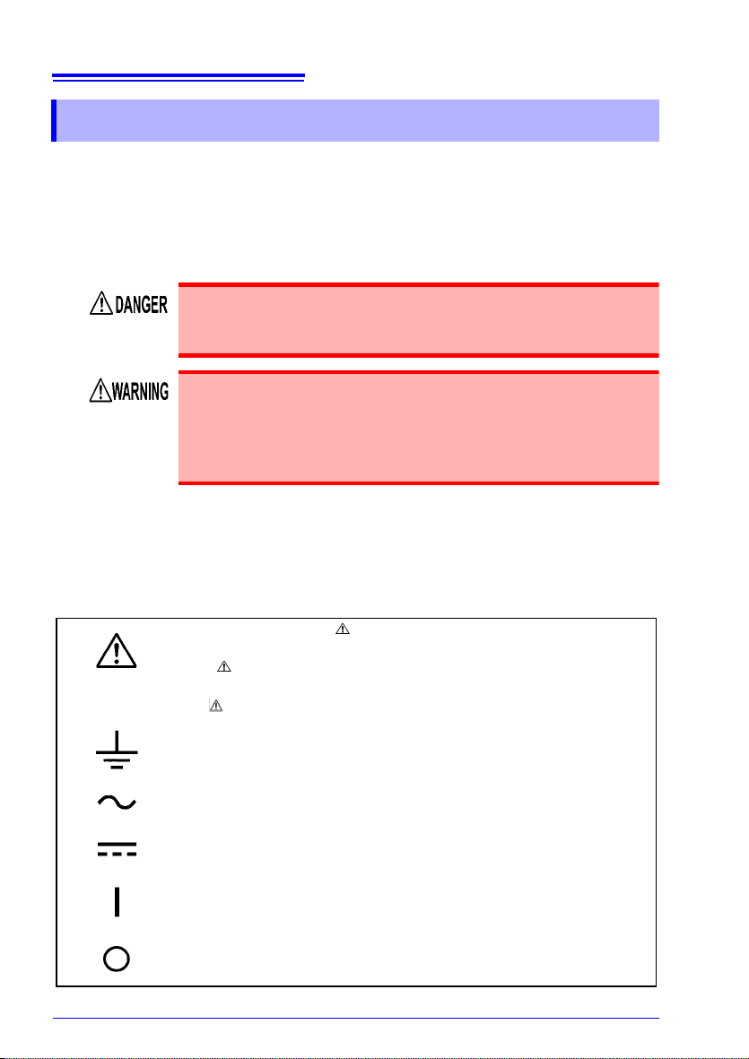
Symbols on the instrument
In the manual, the symbol indicates particularly important
information that the user should read before using the instrument.
The symbol printed on the instrument indicates that the user
should refer to a corresponding topic in the manual
the symbol) before using the relevant function.
Indicates a grounding terminal.
Indicates AC (Alternating Current).
Indicates DC (Direct Current).
Indicates the ON side of the power switch.
Indicates the OFF side of the power switch.
(marked with
5
Ni-MH
Safety Information
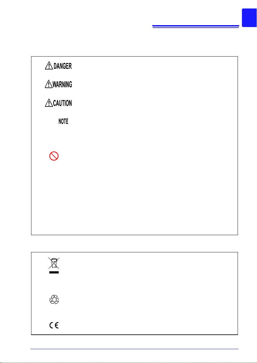
Notation
The following symbols in this manual indicate the relative importance of cautions
and warnings.
Indicates that incorrect operation presents an extreme hazard
that could result in serious injury or death to the user.
Indicates that incorrect operation presents a significant hazard
that could result in serious injury or death to the user.
Indicates that incorrect operation presents a possibility of injury
to the user or damage to the instrument.
Indicates advisory items related to performance or correct operation of the instrument.
(p.)
*
Windows
[ ]
Dialog
Indicates the location of reference information.
Indicates the prohibited action.
Indicates that descriptive information is provided below.
Unless otherwise specified, “Windows” represents Windows XP,
Windows Vista (32bit), or Windows 7 (32bit/64bit).
Names of settings, buttons, and other screen elements are
enclosed in brackets.
Dialog box represents a Windows dialog box.
Symbols for various standards
WEEE marking:
This symbol indicates that the electrical and electronic appliance is put on the EU market after August 13, 2005, and producers of the Member States are requ
appliance under Article 11.2 of Directive 2002/96/EC (WEEE).
This is a recycle mark establis
cling Promotion Law (only for Japan).
ired to display it on the
hed under the Resource Recy-
This symbol indicates that the product conforms to regulatio ns
t by the EC Directive.
set ou

6
Safety Information
Accuracy
We define measurement tolerances in terms of f.s. (full scale), rdg. (reading) and
dgt. (digit) values, with the following meanings:
f.s.
rdg.
dgt.
Measurement categories
This device complies with CAT III (600 V)/ IV (300 V) safety requirements.
To ensure safe operation of measuremen t roducts, IEC 61010 establishes safety
standards for various electrical environments, categorized as CAT II to CAT IV, and
called measurement categories.
CAT II
CAT III
CAT IV
(maximum display value or scale length)
The maximum displayable value or scal
name of the currently selected range.
(reading or displayed value)
The value currently being measured and indicated on the me asuring
instrument.
(resolution)
The smallest displayable unit on a digi
the input value that causes the digital display to show a "1" as the
least-significant digit.
Primary electrical circuits in equipment connected to an AC electrical
outlet by a power cord (portable tools, household appliances, etc.)
CAT II covers directly measuring electrical outlet receptacles.
Primary electrical circuits of heavy equipment (fixed installations)
connected directly to the distribution panel, and feeders from the distribution panel to outlets.
The circuit from the service drop to the service entrance, and to the
power meter and primary overcurrent protection device (distribution
panel).
e length. This is usually the
tal measuring instrument, i.e.,
Using a measurement device in an environment designated with a higher-numbered
category than that for which the device is rated could result in a severe accident, and
must be carefully avoided.
Use of a measurement instrument that is not CAT-rated in CAT II to CAT IV measurement applications could result in a severe accident, and must be carefully
avoided.
7
Operating Precautions
Operating Precautions
Follow these precautions to ensure safe operation and to obtain the full benefits of
the various functions.
Preliminary Checks
Before using the instrument for the first time, verify that it operates normally to
ensure that no damage occurred during storage or shipping. If you find any damage,
contact your authorized Hioki distributor or reseller.
Before using the instrument, verify that damage to any of the
voltage cords’ insulation has not revealed the white (insulator) part of the cord or its metallic conductor. Cord damage
may result in electric shock. Replace with part number L9438-
53.
Instrument Installation
Storage temperature and humidity range
-20°C to 60°C (-4°F to 140°F), 80%RH or less (non-condensating)
If the instrument will not be used for an extended period, remove the battery pack
and store at a temperature from -20°C to 30°C (-4°F to 86°F).
Operating temperature and humidity range
-10°C to 50°C (14°F to 122°F), 80%RH or less (non-condensating)
When operating on battery power: 0°C to 40°C (32°F to 104°F)
When charging the battery: 10°C to 40°C (50°F to 104°F)
When sending or receiving data over a LAN: 0°C to 50°C (32°F to 122°F)
Avoid the following locations that could cause an accident or damage to the instrument.
Exposed to direct sunlight
Exposed to high temperature
Exposed to water, oil,
other chemica
ventsExposed to high
humidity or con
Exposed to high levels of
rticulate dust
pa
Subject to vibration
ls, or sol-
densation
In the presence of corrosive or explosive gases
Exposed to strong electromagnetic fields
Near electromagnetic
iators
rad
Near induction heating
syste
ms
(e.g., high-frequency
indu
ction heating systems
and IH cooking utensils)
8
Operating Precautions
Handling the Instrument
• To avoid damage to the instrument, protect it from physical
shock when transporting and handling. Be especially careful to
avoid physical shock from dropping.
• This instrument may cause interference if used in residential
areas. Such use m
measures to reduce electromagnetic emissions to prevent interference to the reception of radio an
Handling the Clamp Sensor
To avoid short circuits and potentially life-threatening hazards, never attach the clamp to a circuit that
than maximum rated voltage to earth, or over bare conduc tors.
• Be careful to avoid dropping the clamps or otherwise subjecting
them to mechanical shock, which could damage the mating sur faces of the core and adversely affect measurement.
• Keep the clamp jaws and core slits free from foreign objects,
which cou
• Keep the clamp closed when not in use, to avoid accumulating
dust or dirt on
with clamp performance.
ld interfere with clamping action.
ust be avoided unless the user takes special
broadcasts.
operates at more
the ma
d television
ting core surfaces, which could interfere
Handling the Cables
To prevent cable damage, do not step on cables or pinch them
between other objects. Do not bend or pull on cables at their base.
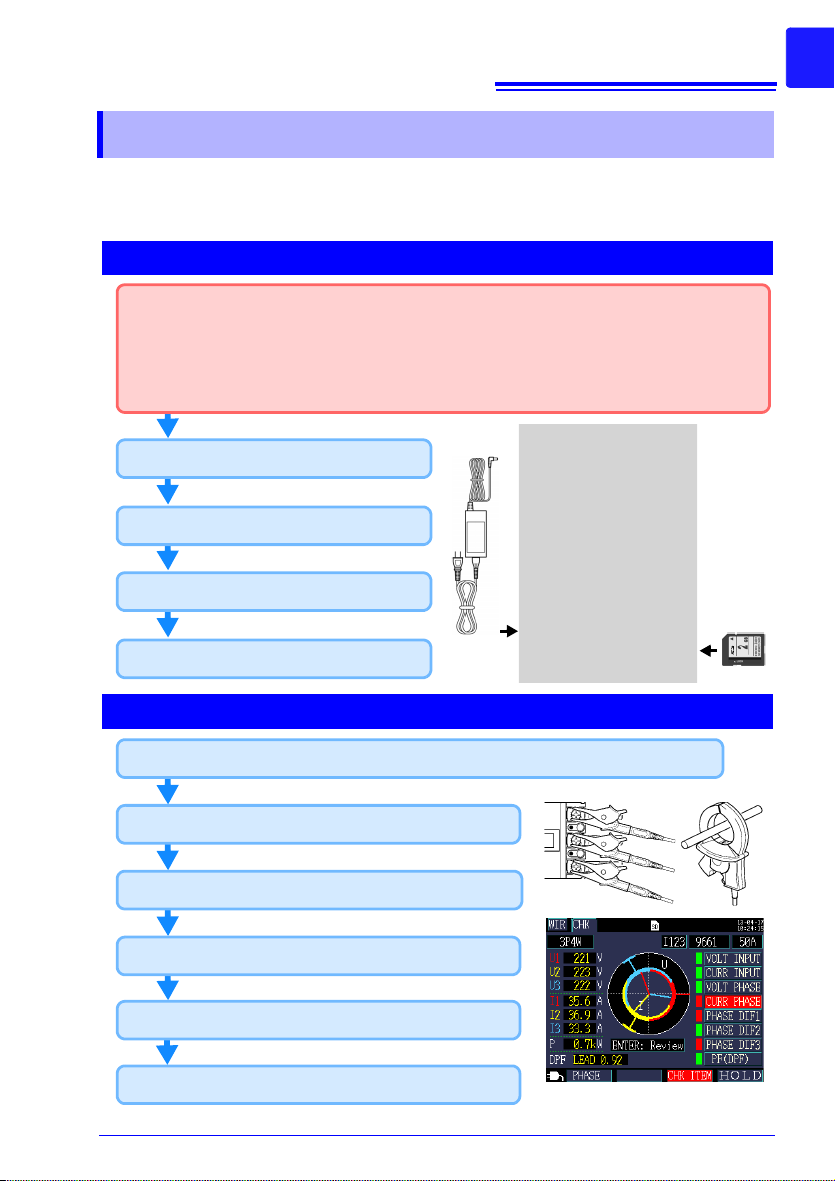
Measurement Flowchart
Wiring check (p. 56)
Setting the current range (p. 54)
Turning the power on (p. 38)
(At purchase)
• Secure the voltage cords together with a spiral tube. (p. 22)
• Wrap the color spiral tubes around the clamp sensor cables. (p. 23)
• Grouping together clamp cables (p. 23)
• Install the battery pack. (p. 24)
• Setting the language and measurement line frequency (p. 28)
Pre-Operation Inspection (p. 29)
Inserting an SD memory card (p. 30)
Supplying power (p. 33)
Connecting to measurement lines (p. 51)(p. 52)
Setting measurement conditions on the Wiring Diagram Screen (p. 43)
Attach voltage cords (p. 47)
Connecting clamp sensors (p. 49)
Wiring Check screen
Measurement preparations
Connecting to lines to be measured and check
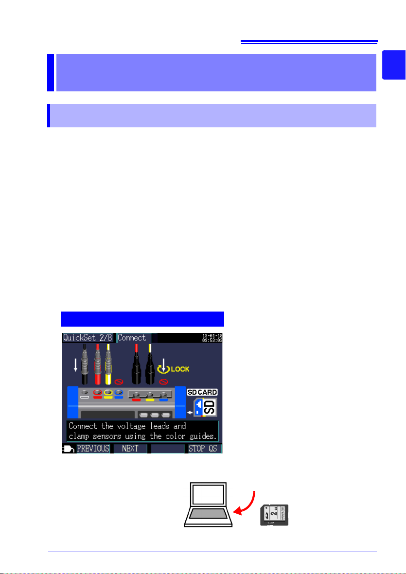
This section presents a series of instrument operations without using the Quick Set
function. For more information about the Quick Set function, see the Measurement
Guide (published separately in color).
9
Measurement Flowchart
10
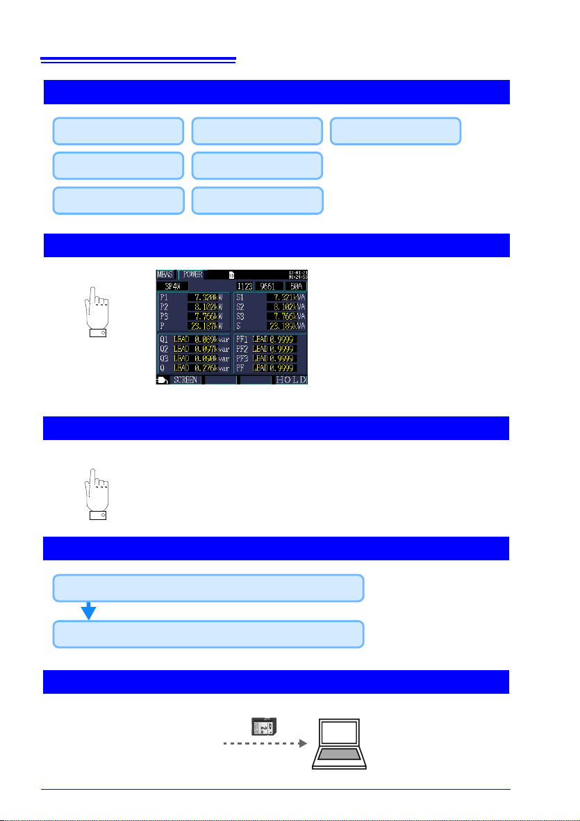
Turn off the instrument.
Starting recording (p . 102) / Stopping recording (p. 105)
Disconnect the cables from the measurement lines.
Save destination
Save interval
Save items
Change the settings of measurement (calculation selection, energy cost), system, and interface
when required.
[MEAS, LIST] screen
Folder/ File name
Recording start
Recording stop
Clock
Measurement is complete
Analyzing data on a computer (p. 129)
Viewing measurement data (p. 83)
Recording settings (p. 69)
Measurement Flowchart
11
Quick Set
1.1 Product Overview
Overview Chapter 1
1.1 Product Overview
The PW3360 Clamp on Power Logger is a clamp-type power meter capable of measuring lines with from single-phase to three-phase four-wire.
In addition to basic measurements including voltage, current, power, power factor,
and energy, the instrument can perform demand measurement and harmonic measurement (PW3360-21 harmonic model only), which are important parameters in
power management.
The Quick Set makes the instrument simple enough to be used even by beginners
by enabling them to configure basic settings, wirings, recording settings, and the
start of recording through a series of steps.
The PW3360 Clamp on Power Logger supports extended data acquisition and automated measurement, thanks to the use of the SD memory card and USB/LAN interface. This makes the PW3360 Clamp on Power Logger suitable for power
measurement at commercial frequencies involved in the power maintenance and
management of a building or factory.
1
Chapter 1 Overview
3

12
1.2 Features
1.2 Features
Quick Set function
The Quick Set function simplifies instrument operation by walking users
through a series of steps to configure basic settings, wirings, wiring check
(wiring confirmation), recording settings, and the start of recording in order to
prevent mistakes.
See: Chapter 7, "Quick Set" (p. 109), Measurement Guide (published separately in color)
Wiring Check (wiring confirmation)
When wirings have been set up improperly, a help function displays hints to
help users establish proper wirings.
See: 3.8, "Verifying Correct Wiring (Wiring Check)" (p. 56)
Ability to make measurements even when power is not available
from a wall outlet
The PW9003 Voltage Line Power Adapter (option) can be used to supply
power from measurement lines.
See: "Supplying Powe r from Measurement Lines (Using the PW9003 Voltage Line Power
Adapter)" (p. 35)
Ability to operate for about 8 hours on battery power
Even when AC power is unavailable, the optional battery pack can be used to
enable about eight hours of measurement.
See: "Installing (replacing) the Battery Pack" (p. 24)
Corresponding to the various power line
The instrument can perform single-phase/2-wire (up to three circuits), singlephase/3-wire, 3-phase/3-wire (2-power measurement/3-power measurement),
and 3-phase/4-wire measurement. When performing single-phase/3-wire, or
3-phase/3-wire 2-power measurement, the instrument can perform power and
leakage current measurement simultaneously.
See: 4.2, "Changing Measurement Settings" (p. 63)
Broad operating temperature range
The instrument can be used at temperatures ranging from -10°C to 50°C.
However, the operating temperature range is limited to 0°C to 40°C when
operating on battery power and from 0°C to 50°C when using the LAN.
TFT color LCD
The instrument uses an LCD that is easy to see in both dim and bright conditions.

13
1.2 Features
Safe design
Despite its compact footprint, the instrument features a safe design that is
CAT IV (300V) and CAT III (600 V) compliant.
Extensive line of clamp sensors
Choose the clamp sensor that’s right for your application, with models
designed for targets ranging from leakage currents to a maximum ranting of
5,000 A.
Ability to store data on SD memory cards
Used with a high-capacity, 2 GB SD memory card, the instrument can record
data continuously for up to one year.
Communications functionality
Instrument settings and data can be downloaded via the instrument’s USB
and LAN interfaces.
See: Chapter 10, "Using Communications (USB/LAN)" (p. 147)
Pulse I/O
Pulse input counts a pulse signal from an external source and saves the result
at a constant interval. Unit consumption management can be performed
based on power data and pulse counts (production volume). During recording
and measurement, pulse output is proportional to active energy.
See: Chapter 11, "Using Pulse Input and Output" (p. 167)
1
Chapter 1 Overview
3
14
Front
Display
3.5" TFT color LCD
(p. 17)
POWER LED
Lights up when the
POWER switch is
turned on and power is
supplied to the instrument. (p. 38)
Flashes if the backlight
has been turned off
due to the AUTO OFF
setting. (p. 77)
Recording LED
Flashing green: When in the
recording standby state
Solid green: When recording
Function key (F1 to F4 key)
Select and change display contents
and settings.
KEY LOCK
Press 3 sec
1.3 Names and Functions of Parts
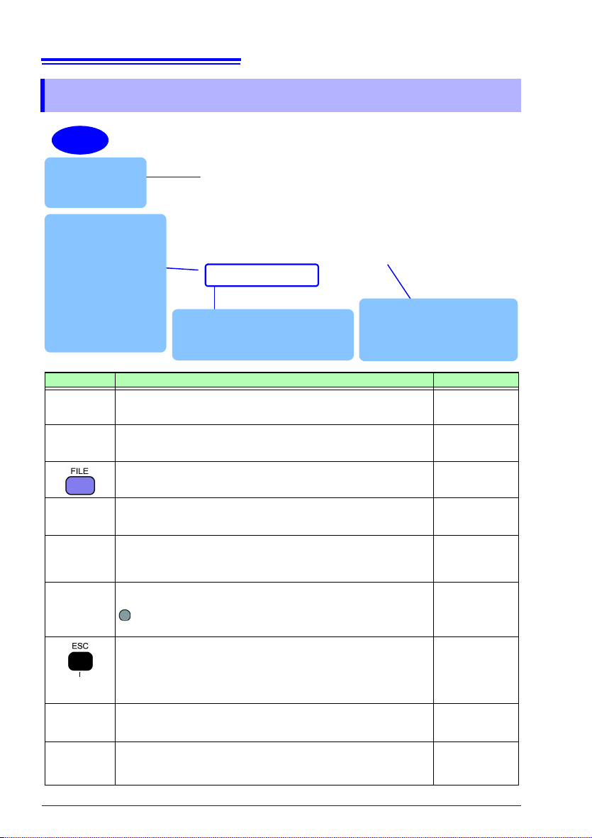
1.3 Names and Functions of Parts
Key Description Reference
Measurement key. Displays the Measurement screen and
switches to the ne
xt screen.
(p. 83)
Settings key. Displays the Settings screen and switches to
the next scree
n.
File key. Displays the File (SD memory card/internal memory) screen and switches screens.
Wiring key. Displays the Wiring Diagram/Wiring Check
screen and switc
hes screens.
Quick Set key. Displays the Quick Set screen and switches
to the next scr
een.
(p. 61)
(p. 113)
(p. 41)
(p. 109),
Measurement
gui
de
Cursor keys. Moves the cursor on the screen. The cursor
keys are also used to scroll graphs and waveforms.
: Enter key. Selects items on the screen and accepts
changes.
Cancel key. Cancels selections and changes, reverting set-
tings to their previous values. Switches to the previous
screen. Pressin
g and holding the Cancel key for 3 or more
seconds activates the key lock (which is canceled by pressing and holding the key again).
Screen Copy key. Outputs an image of the currently displayed screen to the SD memory card.
(p. 121)
Start/Stop key. Starts and stops recording. (p. 101)

Right
Left
LAN interface
Connect a computer here using the optional LAN cable.
See: (p. 155)
SD memory card slot
Insert an SD memory card here.
Be sure to close the cover when
recording.
See: (p. 30)
USB interface
Connect a computer here using
the included USB cable.
See: (p. 148)
AC adapter hook
Loop the AC adapter cord
through this hook.
See: (p. 33)
Power switch
Turns the instrument on and off.
See: (p. 38)
AC adapter
connection
jack
See: (p. 33)
Pulse I/O terminal
Pulse input: Counts pulse input from an
external source.
Pulse output: Generates pulse output
based on integrated energy values.
See: (p. 167)
Charge LED
Lights up while the 9459
Battery Pack is charging.
See: (p. 24)
15
1.3 Names and Functions of Parts
1
Chapter 1 Overview
3

16
Back
Upper
Voltage input terminals
Connect the included L9438-53
Voltage Cord here.
See: (p. 51)
Current input terminals
Connect optional clamp sensors here.
See: (p. 52)
MAC address label
Displays the instrument's unique
MAC address, which is used when
configuring a LAN connection. Do
not remove the label as the information it contains is necessary in
order to manage the device.
Serial number
Displays the instrument's serial number. Do not remove the label as the
information is contains is necessary
in order to manage the device.
Protector
Remove when using the battery. Connect the
PW9002 Battery Set (including the 9459 Battery Pack
and a battery case).
See: (p. 24)
Indicates the CE
mark, KC mark,
WEEE Directive
mark, and country of
manufacture.
1.3 Names and Functions of Parts
17
POWER
INTEGRATE
WAVEFORM
ZOOM
VOLT/CURR(U/I)
DEMAND
TREND
HARMONIC GRAFT
(PW3360-21 only)
HARMONIC LIST
(PW3360-21 only)
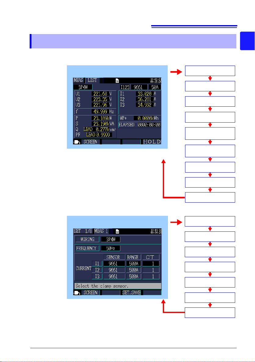
Measurement screen
LIST
Setting screen
MEAS 1
REC 1
REC 2
SYS 1
SYS 2
PULSE
MEAS 2
LAN
See: Chapter 5, "Viewing Measurement Data" (p. 83)
See: Chapter 4, "Changing Settin gs" (p. 61)
1.4 Screen Configuration
1.4 Screen Configuration
1
Chapter 1 Overview
3
18
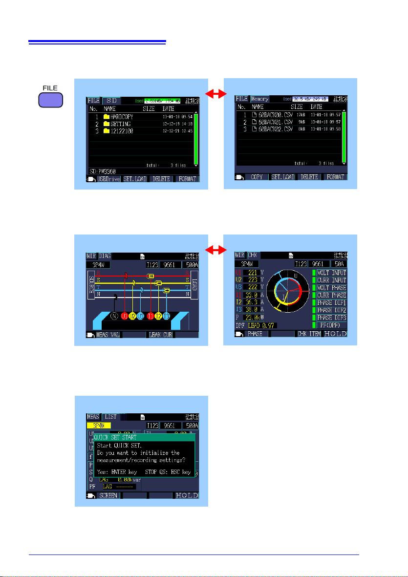
Wiring Screen
Wiring Diagram
Wiring Check
See: Chapter 3, "Connecting to Lines to be Measured" (p. 41)
File Screen
SD card
Memory
See: Chapter 8, "Saving Data and Manipulating Files" (p. 113)
Quick Set Screen
Quick Set Start
See: Chapter 7, "Quick Set" (p. 109)
Measurement Guide (published separately in color)
1.4 Screen Configuration
19
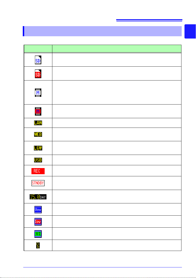
1.5 On-Screen Indicators
1.5 On-Screen Indicators
Marks Description
Lights up when the save destination is [SD CARD] and an SD
memory card is loaded in the instrument.
Lights red when the SD memory card is being accessed.
Lights up when the save destination is the instrument’s internal
memory
tion set to [SD CA
saved to the instrument’s internal memory).
Lights red when the instrument’s internal memory is being
accessed.
Indicates that data is being sent or received over the LAN. (p. 161)
Indicates that data is being sent or received by the HTTP server
functio
Indicates that data is being sent or received both over and LAN and
by th
Indicates that data is being sent or received by the USB interface.
. Lights up when recording is started with the save destina-
RD] but no card inserted (in this case, data will be
n. (p. 163)
e HTTP se
rver.
1
Chapter 1 Overview
3
Indicates that recording and measurement are in progress.
Indicates that the instrument is standing by for recording and mea-
surement to start.
Indicates how much recording time remains on the SD memory
card or in
Lights up when the voltage exceeds the peak.
Lights up when the current exceeds the peak.
Lights up when both the voltage and current exceed the peak.
Lights up when the key lock has been activated. (p. 14)
the
instrument’s internal memory.
20
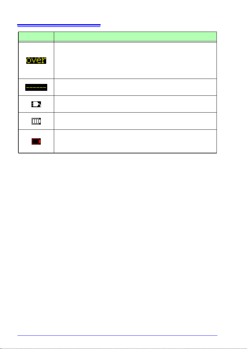
1.5 On-Screen Indicators
Marks Description
Indicates that the display range upper limit has been exceeded,
causing an over-range event. (p. 180)
If the voltage is over-range, the voltage that the instrument is capable of measuring is being exceeded
instrument. If the current is over-range, increase the current range.
Indicates that measurement is not possible. Power factor cannot be
measured w
Lights up when the PW3360 is being operated using the AC
adapt
Lights up when the PW3360 is being operated on battery power. (p.
24)
Lights up when the PW3360 is being operated on battery power
a
nd th
adapter and charge the battery. (p. 24)
hen there is no input.
er. (p. 33)
ere is inadequate battery life remaining. Connect the AC
diately disconnect the
. Imme

Measurement
(At purchase)
(At purchase)
Wrap the color spiral tubes
around the clamp sensor cables.
(p. 23)
2
Connect the AC adapter.
(p. 33)
Insert an SD memory card.
(p. 30)
6
7
3
8
Secure the voltage cords together with a spiral tube.
(p. 22)
1
(At purchase)
Install the battery
pack. (p. 24)
Turn on the instrument. (p. 38)
Perform the pre-measurement
inspection. (p. 29)
5
Set the language and measurement line frequency
(p. 28)
4
(At purchase)
21
2.1 Preparation Flowchart
Preparations
Before starting measurement, connect accessories and options to the instrument.
Before performing measurement, be sure to inspect the instrument as well as any
accessories and options for possible malfunctions.
2.1 Preparation Flowchart
Follow the procedure described below to prepare for measurement.
Chapter 2
2
Chapter 2 Measurement Preparations
3
22
Model L9438-53
Voltage Cord
Banana Plug Leads three, one each black, red, and yellow
Alligator Clips three, one each black, red, and yellow
Five Spiral Tubes
(for cable bundling)
Spiral Tubes
Yellow
Black
Red
Yellow
Black
Red
Insert securely
all the way.
• Model 9804-01 Magnet Adapter
(optional, red, standard screws: M6 pan-head screw)
• Model 9804-02 Magnet Adapter
(optional, black, standard screws: M6 pan-head screw)
φ11 mm
2.2 Preparing to Use the Instrument after Purchase
2.2 Preparing to Use the Instrument after
Purchase
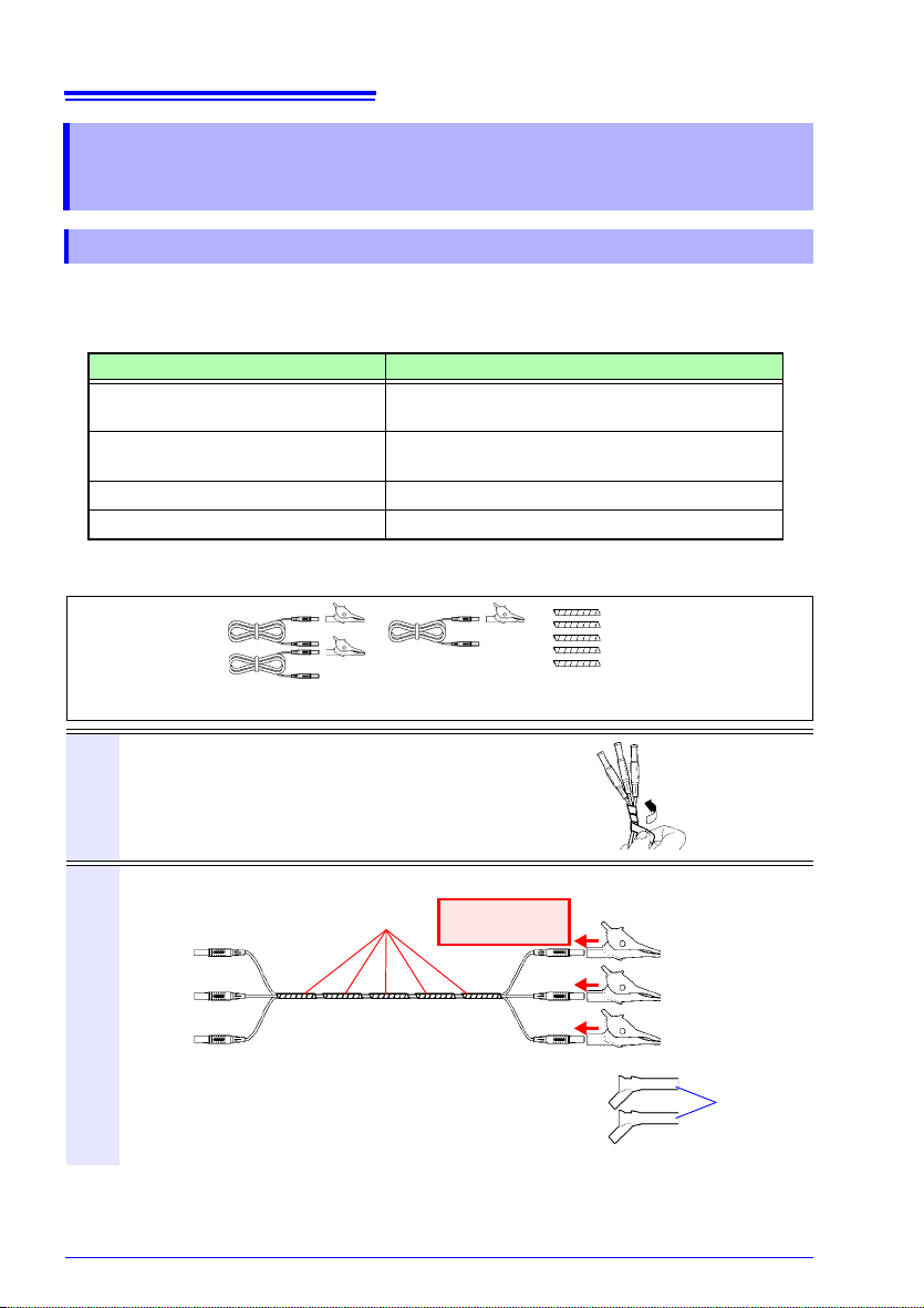
Bundle the Voltage Cord Leads with the Spiral Tubes
5 Spiral Tubes provided with Model L9438-53 Voltage Cord. Use the Spiral Tubes as
and when required. The number of voltage cords that will be bound together
depends on the measurement target.
Measurement target Voltage cord to use (color)
Single-phase/2-wire (1P2W),
Single-phase/3-wire (1P3W1U)
Single-phase/3-wire (1P3W),
3-phase/3-wire (3P3W2M)
3-phase/3-wire (3P3W3M)
3-phase/4-wire (3P4W)
Preparation items:
single-phase/3-wire (1P3W) and 3-phase/3-wire (3P3W2M)
Two cords (black and red)
Three cords (black, red, and yellow)
Three cords (red, yellow, and blue)
Four cords (black, red, yellow, and blue)
Line up the ends of the voltage cords and
1
wrap the spiral tube around them.
Wind a Spiral Tube round the multiple cords.
Five Spiral Tubes are provided. Please wind the
tubes at appropriate intervals.
Insert the same color alligator clip into each lead.
2
You can also use magnet adapters instead of alligator clips.
 Loading...