

Page 1

Communication Command Instruction Manual
PW3336(-01,-02,-03)
PW3337(-01,-02,-03)
Power Meter
This manual explains the communication commands for the above Power Meter
models only.
Please refer to the instruction manual for your Power Meter for details regarding
command settings.(Chapter 4 “Connection to a PC”)
Although all reasonable care has been taken in the production of this manual, should you
find any points which are unclear or in error, please contact your local distributor or the
HIOKI International Sales & Marketing Division at os-com@hioki.co.jp.
In the interest of product development, the contents of this manual may be
subject to revision without notice.
Unauthorized reproduction or copying of this manual is prohibited.
Be sure to review the Instruction Manual for your Power Meter before using the
instrument.
PW3336A987-01
Page 2

Contents
1 Introduction
Message Format
Output Queue and Input Buffer
Status Byte Register
Event Registers
Initialization Items
Command Execution Time
Errors During Communications
Message
2
Standard Commands
Device-specific Commands (Event Registers)
Device-specific Commands (Measurement Settings)
Device-specific Commands (Voltage Range)
Device-specific Commands (Current Range)
Device-specific Commands (Frequency Range [Zero-crossing Filter])
Device-specific Commands (Synchronization Source)
Device-specific Commands (VT/CT Ratio)
Device-specific Commands (D/A Output)
Device-specific Commands (Instrument Display Settings)
Device-specific Commands (Measurement Value Output)
Device-specific Commands (Measurement Value Output Settings [Harmonic Wave])
Device-specific Commands (Communications)
Message Reference ..................................................................................................................................... 33
3
Message Reference Interpretation
Standard Commands
(1) System Data Command ............................................................................................................... 34
(2)
(3)
(4)
Device-specific Commands
(1)
(2)
(3)
(4)
(5)
(6)
(7)
(8)
(9)
(10)
(11) Communications Settings
(12) Status-dependent Commands (Common Commands)
(13) Status-dependent Commands (Device-specific Commands)
4 Operation Problems (Communications) ................................................................................................ 113
5 Device Documentation Requirements .................................................................................. 115
..................................................................................................................................................... 1
............................................................................................................................................ 2
................................................................................................................... 5
...................................................................................................................................... 6
............................................................................................................................................. 8
....................................................................................................................................... 13
......................................................................................................................... 14
................................................................................................................ 14
............................................................................................................................................... 15
List
.................................................................................................................................. 15
........................................................................................ 15
............................................................................ 16
.......................................................................................... 16
.......................................................................................... 17
.............................................. 18
......................................................................... 18
............................................................................................... 19
................................................................................................ 20
................................................................... 21
.................................................................... 22
..................... 29
...................................................................................... 32
............................................................................................................ 33
.................................................................................................................................. 34
Internal Operation Command
Synchronization Commands
Status and Event Control Commands
....................................................................................................................... 38
Event Status Register
Measurement Settings
Voltage Range
Current Range
Frequency Range (Zero-crossing Filter)
Synchronization Source
VT Ratio/CT Ratio
D/A output
Instrument Display Settings
Measurement Value Output
............................................................................................................................... 44
.............................................................................................................................. 46
..................................................................................................................................... 53
................................................................................................................... 38
......................................................................................................................... 51
...................................................................................................... 34
...................................................................................................... 35
........................................................................................ 36
................................................................................................................. 40
................................................................................... 49
.............................................................................................................. 50
....................................................................................................... 55
........................................................................................................ 60
........................................................................................................ 103
......................................................... 108
.............................................. 109
PW3336A987-01
Page 3
1
Program Messages
Response Messages
Controller
PW3336
PW3337
1 Introduction
This manual is for Power Meter models PW3336(-01, -02, -03) and PW3337(-01, -02, -03).
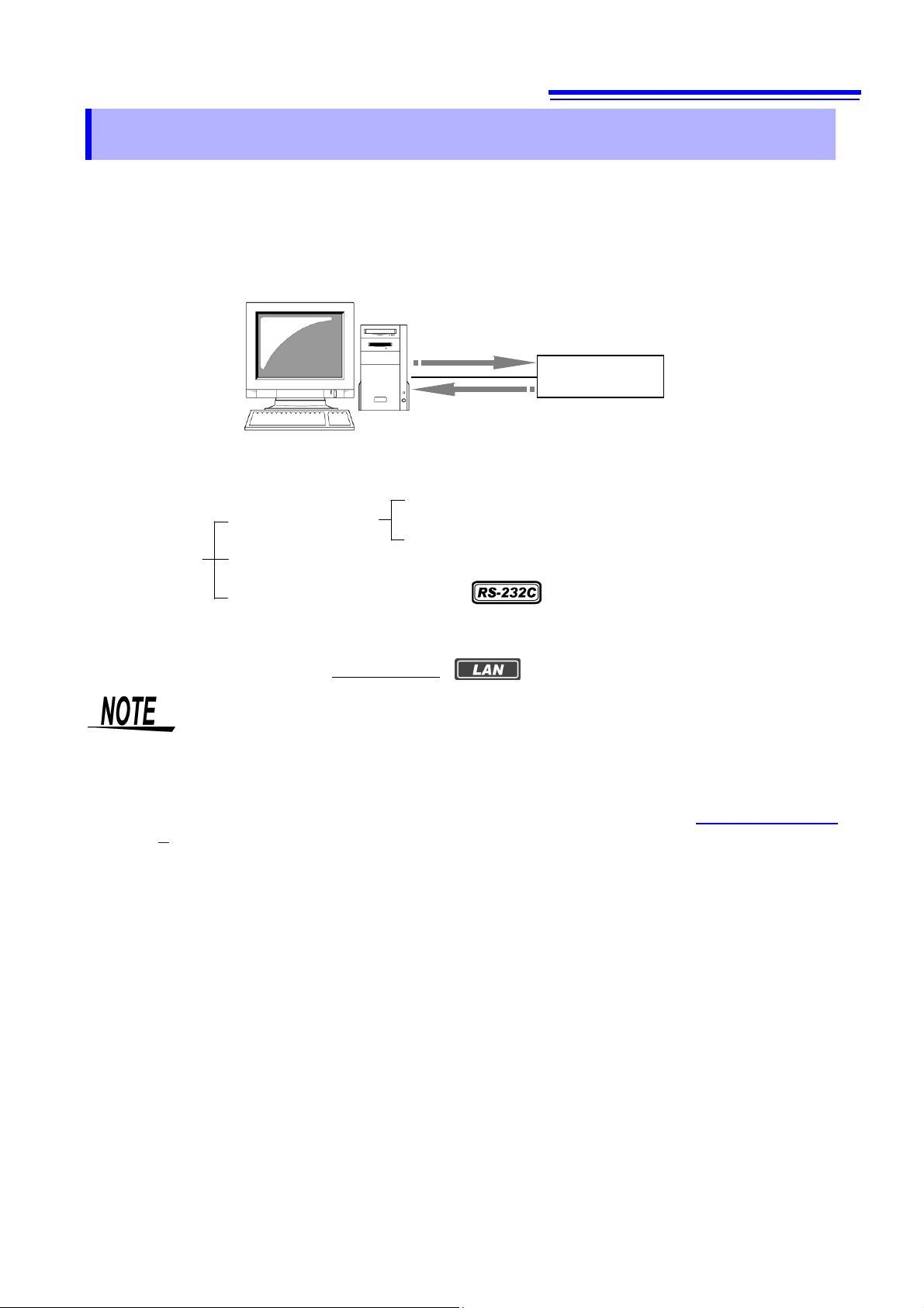
Messages are provided in the interface to control the Power Meter.
There are two types of messages: program messages that are sent from the controller (such as a computer) to the
Power Meter and response messages that are sent from the Power Meter to the controller.
There are also execution confirmation messages for synchronization with the controller in the RS-232C interface.
Message types are further categorized as follows.
Program Messages
Messages Response Messages
Execution Confirmation Messages
When issuing commands that contain data, make sure that the data is provided in the specified format.
When connecting via LAN, connect to TCP/IP port 3300.
Command Messages
Query Messages
During communication the Power Meter will enter the Remote state and the REMOTE Indicator on the unit will
turn ON.
When this occurs, all operation keys except for SHIFT(EXIT/LOCAL) will be disabled.
However, if the Power Meter is in the Local Lock Out state via GP-IB (GP-IB command LLO:Local Lock Out ->
P.12), the SHIFT(EXIT/LOCAL) Key will also be disabled. If this occurs, execute the GTL (Go To Local)
interface function or turn the Power Meter OFF and ON again to return to the Local state.
If the Power Meter enters the Remote state when on the settings screen, it will automatically change to the
measurement display.
PW3336A987-01
Page 4

2
Message Format
Program Messages
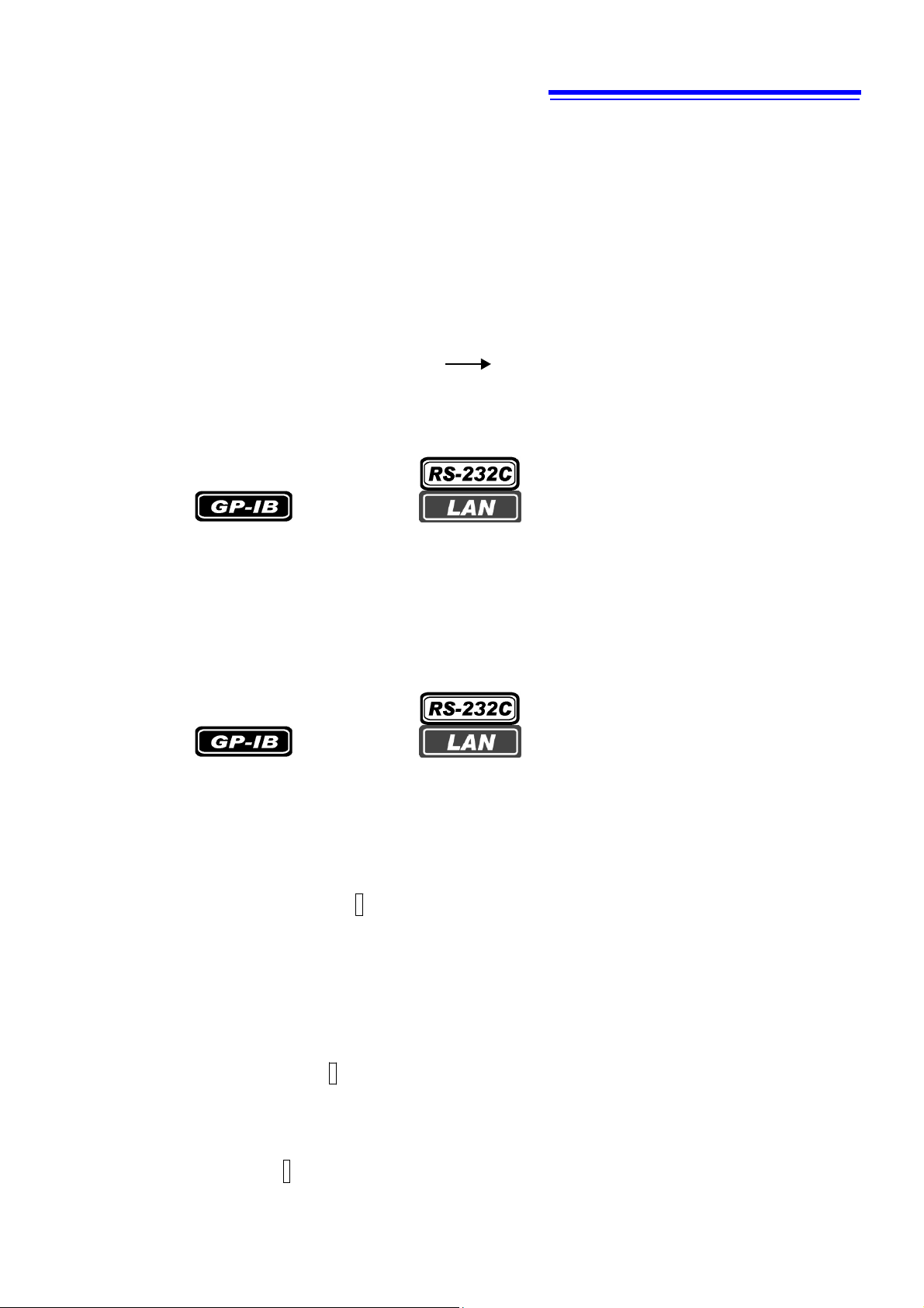
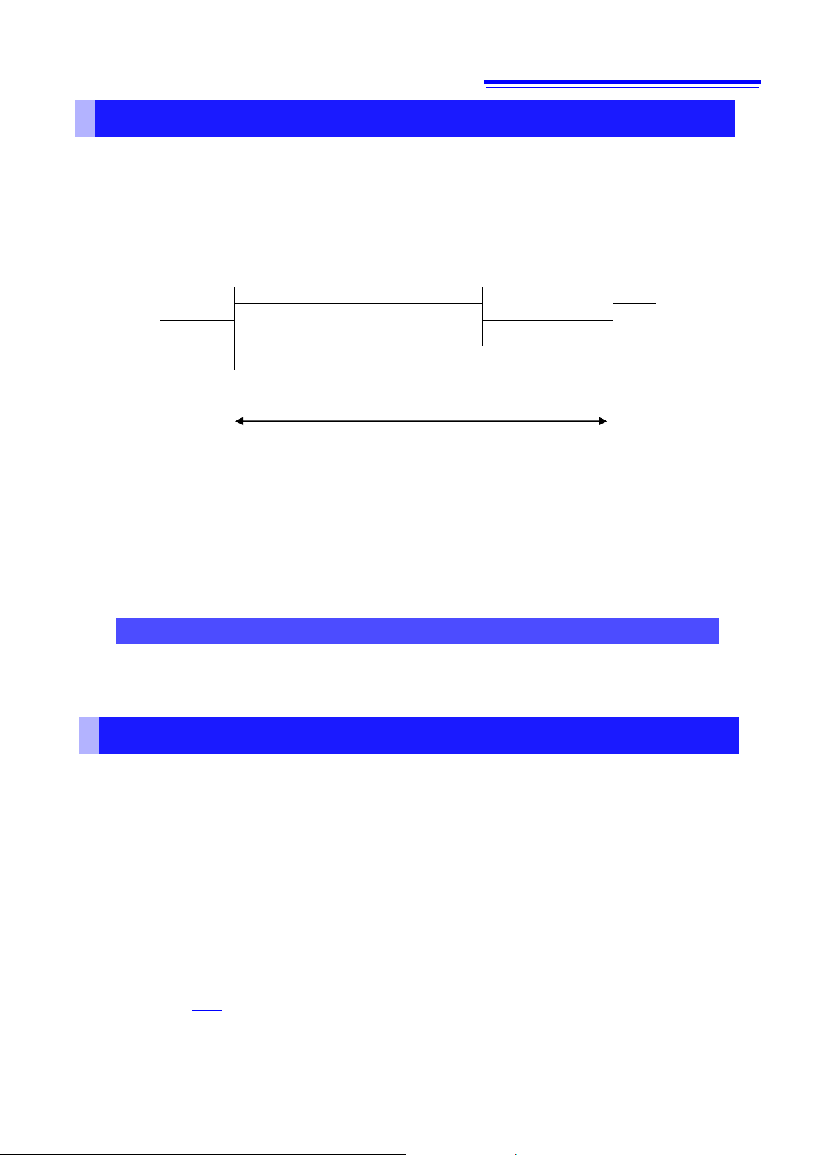
Program messages can be either Command Messages or Query Messages.
(1) Command Messages
Instructions to control the instrument, such as to change settings or reset
Example: Instruction to set the voltage range (ch1).
:VOLTAGE1:RANGE 300
Header portion Space Data portion
(2) Query Messages
Requests for responses relating to results of operation or
measurement, or the state of instrument settings
Example: Request for the current measurement range
:VOLTAGE1:RANGE?
See: "Headers (p. 2)", "Separators (p. 3)", "Data Formats (p.4)"
Response Messages
When a query message is received, its syntax is checked and a response message is generated.The :HEADer command determines whether headers are prefixed to response messages.
Header ON :VOLTAGE1:RANGE 300
Header OFF 300
At power-on, Header ON is selected.
If an error occurs when a query message is received, no response message is generated for that query.
Command Syntax
Command names are chosen to mnemonically represent their function, and can be abbreviated. The full
command name is called the “long form”, and the abbreviated name is called the “short form”. The
command references in this manual indicate the short form in upper-case letters, extended to the long form
in lower case letters, although the commands are not case-sensitive in actual usage.
DISPLAY?
DISP?
DISPL?
DIS?
Response messages generated by the instrument are in long form and in upper case letters.
Headers
Headers must always be prefixed to program messages.
(1) Command Program Headers
There are three types of commands: Simple, Compound, and Standard.
• Headers for Simple Commands
This header type is a sequence of letters and digits.
:ESE0
• Headers for Compound Commands
These headers consist of multiple simple command type headers separated by colons ":".
:VOLTage1:RANGE
Header portion Question mark
(The current voltage range for ch1 is 300 V.)
OK ( long form
OK ( short form
Error
Error
)
)
PW3336A987-01
Page 5
3
•
LF
•
CR+LF
•
EOI
•
LF
with an EOI
•
CR
•
CR+LF
•
LF
with an EOI
•
CR
+ LF
with an EOI (default)
•
LF
•
CR+LF (default)
• Headers for Standard Commands
This header type begins with an asterisk "*", indicating that it is a standard command defined by IEEE 488.2.
*RST
(2) Query Program Header
These commands are used to query the instrument about the results of operations, measured values, and the
current states of instrument settings.
As shown in the following examples, a query is formed by appending a question mark ? after a program header.
:HOLD?
:VOLTage:RANGe?
Characters within square brackets [ ] may be omitted.
Either form is valid
:MEASure[:NORMAL]:VALue? :MEASure:VALue?
Message Terminators
The instrument recognizes the following message terminators (delimiters):
Depending on the instrument's interface settings, the following can be selected as the terminator for response
messages.
For information on settings, see "Terminator Setting" (p. 107).
Separators
(1) Message Unit Separator
Multiple messages can be written in one line by separating them with semicolons ";".
:VOLTage1:RANGe 300;:AVERaging 10
• When messages are combined in this way and if one command contains an error, all subsequent messages
up to the next terminator will be ignored.
(2) Header Separator
In a message consisting of both a header and data, the header is separated from the data by a space
“ ” (ASCII code 20H).
: VOLTage1: RANGe 300
(3) Data Separator
In a message containing multiple data items, commas are required to separate the data items from one another.
:MEASure? U1, I1
PW3336A987-01
Page 6

4
The instrument does not completely support IEEE 488.2. Use referenced data whenever possible.
Also be careful not to overflow the input buffer or output queue with a single command.
Data Formats
The instrument uses character data, decimal numeric data and character string data depending on the command.
(1) Character Data
Character data always begins with an alphabetic character, and subsequent characters may be either
alphabetic or numeric. Character data is not case-sensitive, although response messages from the instrument
are only upper case. When the command data portion contains <1/0/ON/OFF>, the operation will be the same
as when 0 is OFF and 1 is ON.
:HEADER OFF
(2) Decimal Numeric Data
Three formats are used for numeric data: NR1, NR2 and NR3. Numeric values may be signed or unsigned.
Unsigned numeric values are handled as positive values. Values exceeding the precision handled by the
instrument are rounded to the nearest valid digit.
NR1 Integer data (e.g.: +12, -23, 34)
•
NR2 Fixed-point data (e.g.: +1.23, -23.45, 3.456)
•
NR3 Floating-point exponential representation data (e.g.: +1.0E-2, -2.3E+4)
•
The term “NRf format” includes all three of the above numeric decimal formats.
The instrument accepts NRf format data. The format of response data is specified for each command, and the
data is sent in that format.
:AVERAGING 10
Compound Command Header Omission
When several commands having a common header are combined to form a compound command (for
example, :VOLTage1:AUTO and :VOLTage1:RANGe), if they are written together in sequence, the common
portion (here, :VOLTage1:) can be omitted after its initial occurrence.
This common portion is called the “current path” (analogous to the path concept in computer file storage), and until
it is cleared, the interpretation of subsequent commands presumes that they share the same common portion.
This usage of the current path is shown in the following example:
Full expression
:VOLTage1:AUTO OFF;:VOLTage1:RANGe 300
Compacted expression
:VOLTage1:AUTO OFF;RANGe 300
The current path allows you to abbreviate the next command.
The current path is cleared when the power is turned on, when reset by key input, by a colon “:” at the start of
a command, and when a message terminator is detected.
Standard command messages can be executed regardless of the current path. They have no effect upon the
current path.
A colon “:” is not required at the start of the header of a Simple or Compound command. However, to avoid
confusion with abbreviated forms and operating mistakes, we recommend always placing a colon at the start of
a header.
PW3336A987-01
Page 7

5
• Power on
• Device clear
• Query error
Output Queue and Input Buffer
Output Queue
Response messages are stored in the output queue until read by the controller. The output queue is also cleared
in the following circumstances:
The output queue capacity of the instrument is 4,096 bytes. If response messages overflow the buffer, a query
error is generated and the output queue is cleared.
Input Buffer
The input buffer capacity of the instrument is 1,024 bytes.
If 1,024 bytes are allowed to accumulate in this buffer so that it becomes full, the GP-IB interface bus enters the
waiting state until space is cleared in the buffer.
The RS-232C and LAN interfaces will not accept data beyond 1,024 bytes.
Note: Ensure that the length of a single line never exceeds 1,024 bytes.
PW3336A987-01
Page 8
6
bit7 bit6 bit5
bit4
bit3
bit2 bit1 bit0
unused
SRQ
ESB
MAV
ESB3
ESB2
ESB1
ESB0
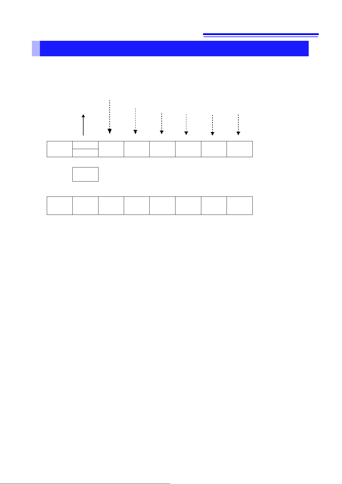
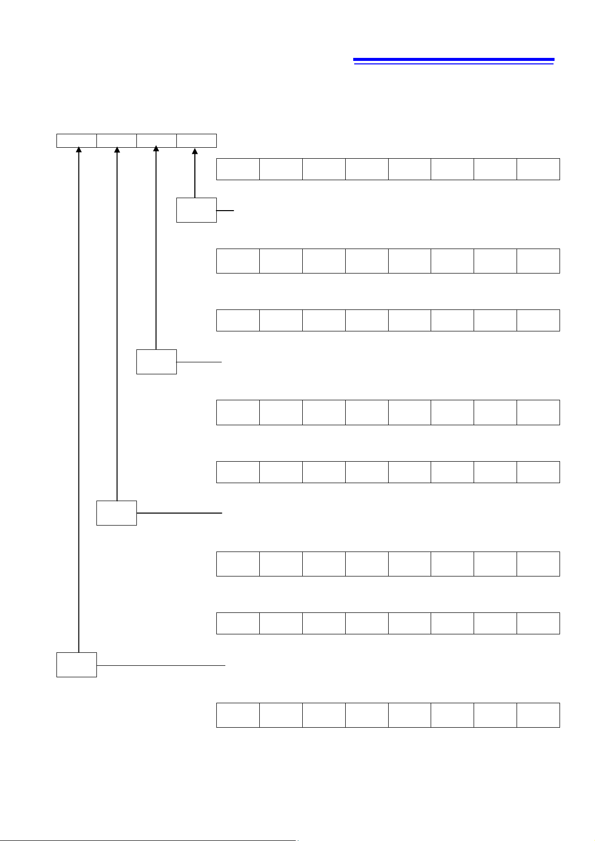
Status Byte Register
(STB)
MSS
↑ ↓ ↓ ↓ ↓ ↓
↓
Logical
sum
←& & & & &
&
↑ ↑ ↑ ↑ ↑
↑
bit7 bit6 bit5
bit4
bit3
bit2 bit1 bit0
unused
0
ESB
MAV
ESB3
ESB2
ESB1
ESB0
Service Request
Enable Register
(SRER)
Status Byte Register
The instrument uses the status model defined by the IEEE 488.2 standard for items related to serial polling
via the service request function.
Events are what trigger service requests.
Standard Event Register Description
Service Request Output Queue data information
SRQ occurrence Each of these bits correspond to a specific event register
Overview of Service Request Occurrence
The Status Byte Register contains information about the event registers and the output queue.
Required items are selected from this information by masking with the Service Request Enable
Register.
When any bit selected by the mask is set, bit 6 (MSS; the Master Summary Status) of the Status Byte
Register is also set, which generates an SRQ (Service Request) message and dispatches a service
request.
SRQs (Service Requests) can be used only with the GP-IB interface.
However, SRER setting (*SRE?) and STB read (*STB?) queries can be used even with the RS-232C
and LAN interfaces.
PW3336A987-01
Page 9

7
Bit 7
unused
Bit 6
SRQ
Set to 1 when a service request is dispatched.
MSS
This is the logical sum of the other bits of the Status Byte Register.
Bit 5
ESB
Standard Event Status (logical sum) bit
This is the logical sum of the Standard Event Status Register.
Bit 4
MAV
Message available
Indicates that a message is present in the output queue.
Bit 3
ESB3
Event Summary (logical sum) bit 3
This is the logical sum of Event Status Register 3.
Bit 2
ESB2
Event Summary (logical sum) bit 2
This is the logical sum of Event Status Register 2.
Bit 1
ESB1
Event Summary (logical sum) bit 1
This is the logical sum of Event Status Register 1.
Bit 0
ESB0
Event Summary (logical sum) bit 0
This is the logical sum of Event Status Register 0.
Status Byte Register (STB)
During serial polling, the contents of the 8-bit Status Byte Register are sent from the instrument to the controller.
When any Status Byte Register bit enabled by the Service Request Enable Register has switched from 0 to 1, the
MSS bit becomes 1. Consequently, the SRQ bit is set to 1, and a service request is dispatched.
The SRQ bit is always synchronous with service requests, and is read and simultaneously cleared during serial
polling. Although the MSS bit is only read by an *STB? query, it is not cleared until a clear event is initiated by the
*CLS command.
Service Request Enable Register (SRER)
Setting a bit of this register to 1 enables the corresponding bit of the
Status Byte Register to be used.
PW3336A987-01
Page 10

8
Bit 7
PON
Power-On Flag
Set to 1 when the power is turned on, or upon recovery from an outage.
Bit 6
URQ
User Request
unused
Bit 5
CME
Command error (The command to the message terminator is ignored.)
This bit is set to 1 when a received command contains a syntactic or semantic
error:
• Program header error
• Incorrect number of data parameters
• Invalid parameter format
• Received a command not supported by the instrument
Bit 4
EXE
Execution Error
This bit is set to 1 when a received command cannot be executed for some
reason.
• The specified data value is outside of the set range
• The specified data cannot be set (data format discrepancy)
• Execution is prevented by some other operation being performed
Bit 3
DDE
Device-dependent Error
This bit is set to 1 when a command cannot be executed due to some reason
other than a command error, a query error or an execution error.
• An internal error occurred and execution cannot be performed (error
displayed)
• A command was received that cannot be executed during a restricted
operation (integration, hold, etc.)
• When "o.r",”S.Err” or ”-----“ occurs and the error data is read by a *MEASure?
query.
Bit 2
QYE
Query Error (the output queue is cleared)
This bit is set to 1 when a query error is detected by the output queue control.
• When an attempt is made to read the output queue when the output queue is
empty (GP-IB only)
• When the data overflows the output queue
• When the next command is received while there is data in the output queue
• When there is a query after a *IDN? on the same line.
Bit 1
RQC
(unused)
Request Control
Bit 0
OPC
Operation Complete
This bit is set to 1 in response to an *OPC command.
• It indicates the completion of operations of all messages up to the *OPC
command
Event Registers
Standard Event Status Register (SESR)
The Standard Event Status Register is an 8-bit register.
If any bit in the Standard Event Status Register is set to 1(after masking by the Standard Event Status Enable
Register), bit 5 (ESB) of the Status Byte Register is set to 1.
See: “
Standard Event Status Enable Register (SESER)” (p.
The Standard Event Status Register is cleared in the following situations:
• When a *CLS command is executed
• When an event register query
• When the instrument is powered on
(
*ESR?) is executed
9)
PW3336A987-01
Page 11
9
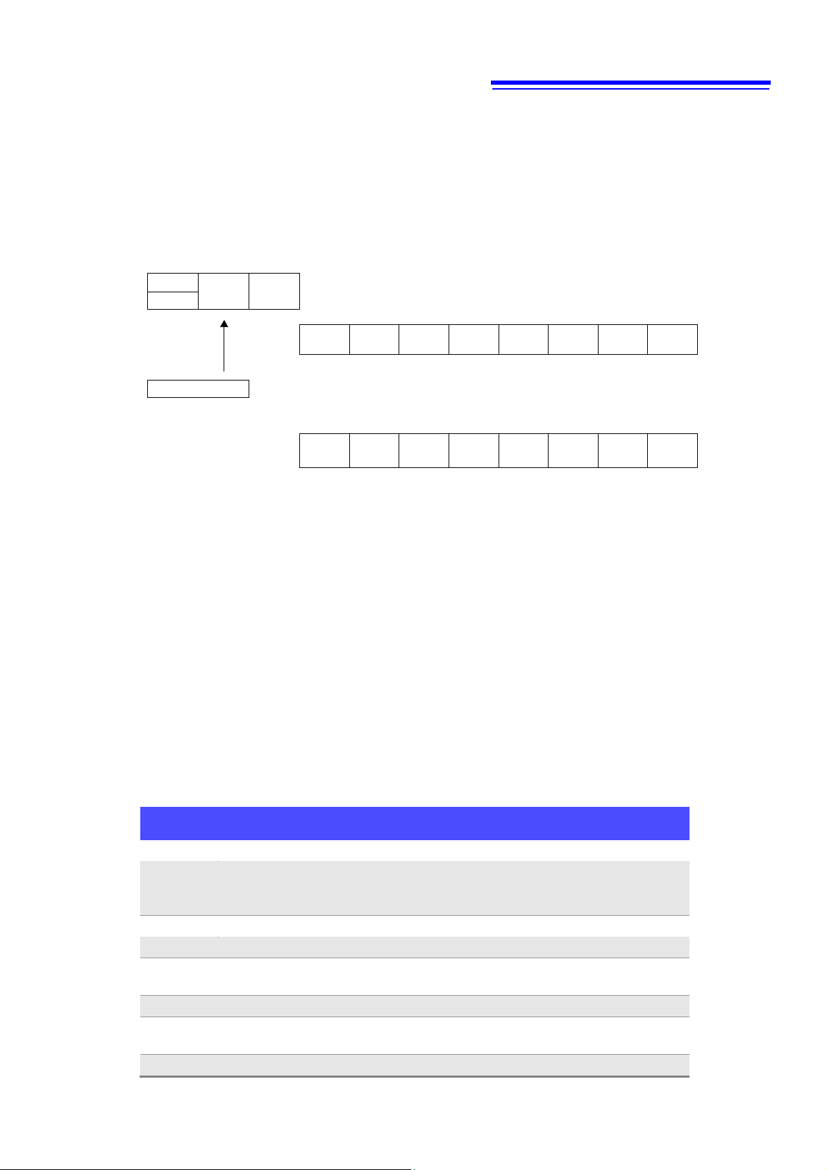
Status Byte Register (STB)
bit6 bit5
bit4
SRQ
ESB
MAV
MSS
Standard Event Status Register (SESR)
bit7 bit6
bit5
bit4
bit3
bit2 bit1 bit0
PON
URQ
CME
EXE
DDE
QYE
RQC
OPC
↓ ↓ ↓ ↓ ↓ ↓ ↓ ↓
Logical sum
← & & & & & & & &
↑ ↑ ↑ ↑ ↑ ↑ ↑ ↑
bit7 bit6
bit5
bit4
bit3
bit2 bit1 bit0
PON
URQ
CME
EXE
DDE
QYE
RQC
OPC
Standard Event Status Enable Register (SESER)
Event Status Register 0 (ESR0)
Bit 7
DataSet
Data updated.
Bit 6
Change
Setting
Err
Data became invalid due to a hardware-related setting change.
(For example, immediately after the range was changed.)
Bit 5
SyncErr
A synchronization error occurred on ch1, ch2, or ch3.
Bit 4
IntegrateEnd
Integration has completed.
Bit 3
AVeraGe
update
Averaged data updated.
Bit 2
HIGH-Psum
The total (sum) of the active power is o.r. (over range).
Bit 1
OverDataIntegrate
A peak overflow of voltage or current occurred in the active
power integration value for total(sum).
Bit 0
Ext.Sync Error
Failed external synchronization for the data update.
Standard Event Status Enable Register (SESER)
Setting any bit of the Standard Event Status Enable Register to 1 enables access to the corresponding bit of the
Standard Event Status Register.
Standard Event Status Register (SESR) and Standard Event Status Enable Register (SESER)
Device-specific Event Status Registers (ESR0, ESR1, ESR2,
and ESR3)
This instrument provides four Event Status Registers for controlling events.
Each event register is an 8-bit register.
When any bit in one of these Event Status Registers enabled by its corresponding Event Status Enable Register
is set to 1, the following happens:
• For Event Status Register 0, bit 0 (ESB0) of the Status Byte Register (STB) is set to 1.
• For Event Status Register 1, bit 1 (ESB1) of the Status Byte Register (STB) is set to 1.
• For Event Status Register 2, bit 2 (ESB2) of the Status Byte Register (STB) is set to 1.
• For Event Status Register 3, bit 3 (ESB3) of the Status Byte Register (STB) is set to 1.
Event Status Registers 0 through 3 are cleared in the following situations:
• When a *CLS command is executed
• When an Event Status Register query (
• When the instrument is powered on
:ESR0?, :ESR1?, :ESR2?
, or
:ESR3?
) is executed
PW3336A987-01
Page 12

10
Event Status Register 1 (ESR1)
Bit 7
Frequency
Out of Range1
The frequency of ch1 (voltage or current) is invalid.
Bit 6
Over
DataIntegrate1
A peak overflow of voltage or current occurred in the active power
integration value for ch1.
Bit 5
CurrentOver
DataIntegrate1
A peak overflow of current occurred in the current integration
value for ch1.
Bit 4
Over-I1
A peak overflow occurred in the current input on ch1.
Bit 3
Over-U1
A peak overflow occurred in the voltage input on ch1.
Bit 2
High-P1
The active power of ch1 is over range.
Bit 1
High-I1
The current of ch1 is over range.
Bit 0
High-U1
The voltage of ch1 is over range.
Event Status Register 2 (ESR2)
Bit 7
Frequency
Out of Range2
The frequency of ch2 (voltage or current) is invalid.
Bit 6
Over
DataIntegrate2
A peak overflow of voltage or current occurred in the active power
integration value for ch2.
Bit 5
CurrentOver
DataIntegrate2
A peak overflow of current occurred in the current integration
value for ch2.
Bit 4
Over-I2
A peak overflow occurred in the current input on ch2.
Bit 3
Over-U2
A peak overflow occurred in the voltage input on ch2.
Bit 2
High-P2
The active power of ch2 is over range.
Bit 1
High-I2
The current of ch2 is over range.
Bit 0
High-U2
The voltage of ch2 is over range.
Event Status Register 3 (ESR3)
Bit 7
Frequency
Out of Range3
The frequency of ch3 (voltage or current) is invalid.
Bit 6
Over
DataIntegrate3
A peak overflow of voltage or current occurred in the active power
integration value for ch3.
Bit 5
CurrentOver
DataIntegrate3
A peak overflow of current occurred in the current integration
value for ch3.
Bit 4
Over-I3
A peak overflow occurred in the current input on ch3.
Bit 3
Over-U3
A peak overflow occurred in the current input on ch3.
Bit 2
High-P3
The active power of ch3 is over range.
Bit 1
High-I3
The current of ch3 is over range.
Bit 0
High-U3
The voltage of ch3 is over range.
PW3336A987-01
Page 13
11
Status Byte Register (STB)
bit3 bit2 bit1
bit0
ESB3
ESB2
ESB1
ESB0
Event Status Register 0 (ESR0)
bit7 bit6 bit5
bit4
bit3
bit2 bit1 bit0
DS
CSE
SE
IE
AVG
HP
ODI
ESE
↓ ↓ ↓ ↓ ↓ ↓ ↓
↓
Logical
sum
& & & & & & &
&
↑ ↑ ↑ ↑ ↑ ↑ ↑
↑
bit7 bit6 bit5
bit4
bit3
bit2 bit1 bit0
DS
CSE
SE
IE
AVG
HP
ODI
ESE
Event Status Enable Register 0 (ESER0)
bit7 bit6 bit5
bit4
bit3
bit2 bit1 bit0
FOR1
ODI1
CODI1
OI1
OU1
HP1
HI1
HU1
↓ ↓ ↓ ↓ ↓ ↓ ↓
↓
Logical
sum
& & & & & & &
&
↑ ↑ ↑ ↑ ↑ ↑ ↑
↑
bit7 bit6 bit5
bit4
bit3
bit2 bit1 bit0
FOR1
ODI1
CODI1
OI1
OU1
HP1
HI1
HU1
Event Status Enable Register 1 (ESER1)
bit7 bit6 bit5
bit4
bit3
bit2 bit1 bit0
FOR2
ODI2
CODI2
OI2
OU2
HP2
HI2
HU2
↓ ↓ ↓ ↓ ↓ ↓ ↓
↓
Logical
sum
& & & & & & &
&
↑ ↑ ↑ ↑ ↑ ↑ ↑
↑
bit7 bit6 bit5
bit4
bit3
bit2 bit1 bit0
FOR2
ODI2
CODI2
OI2
OU2
HP2
HI2
HU2
Event Status Enable Register 2 (ESER2)
bit7 bit6 bit5
bit4
bit3
bit2 bit1 bit0
FOR3
ODI3
CODI3
OI3
OU3
HP3
HI3
HU3
↓ ↓ ↓ ↓ ↓ ↓ ↓
↓
Logical
sum
& & & & & & &
&
↑ ↑ ↑ ↑ ↑ ↑ ↑
↑
bit7 bit6 bit5
bit4
bit3
bit2 bit1 bit0
FOR3
ODI3
CODI3
OI3
OU3
HP3
HI3
HU3
Event Status Enable Register 3 (ESER3)
Event Status Register 0 to 3 (ESR0 to ESR3) and
Event Status Enable Register 0 to 3 (ESER0 to ESER3)
PW3336A987-01
Page 14

12
Register
Read
Write
Status Byte Register
*STB?
-
Service Request Enable Register
*SRE?
*SRE
Standard Event Status Register
*ESR?
-
Standard Event Status Enable Register
*ESE?
*ESE
Event Status Register 0
:ESR0?
-
Event Status Enable Register 0
:ESE0?
:ESE0
Event Status Register 1
:ESR1?
-
Event Status Enable Register 1
:ESE1?
:ESE1
Event Status Register 2
:ESR2?
-
Event Status Enable Register 2
:ESE2?
:ESE2
Event Status Register 3
:ESR3?
-
Event Status Enable Register 3
:ESE3?
:ESE3
Command
Description
GTL
Go To Local
Changes the instrument from the Remote state to the Local
state.
LLO
Local Lock Out
Locks all keys on the instrument, including the Local Key.
DCL
Device CLear
Clears the input buffer and output queue.
SDC
Selected Device Clear
Clears the input buffer and output queue.
GET
Group Execute Trigger
Updates the displayed value while it is being held.
Register Reading and Writing
GP-IB Commands
The following commands can be used through interface functions.
PW3336A987-01
Page 15

13
Initialization Method
Item
At
Power-on
System
Reset
*RST
Command
Device
Clear
(GP-IB only)
*CLS
Command
Factory
Default
GP-IB address
- - - - -
1
RS-232C setting (baud rate)
- - - - -
38400
LAN setting
- - - - -
*4
Device-specific functions (range,
etc.)
-
●
●
-
-
*4
Output Queue
●
●
- ● -
●
Input Buffer
●
●
- ● -
●
Status Byte Register
●
●
-
-*1
●*2
●
Event registers
●*3
●
-
-
●
●
Enable register
●
●
- - -
0
Current path
●
●
- ● -
●
Headers on/off
● ● ●
-
-
ON
Output items
● ● ●
*5,
Response message terminator
●
●
- - -
CR+LF
Response message separator
● ● ●
-
-
;
*1. Only the MAV bit (bit 4) is cleared.
*2. All bits except the MAV bit are cleared.
*3. Except the PON bit (bit 7).
*4. Refer to the user's manual for the instrument.
*5. See below.
ch
Measurement Item
CH1
CH2
CH3
(PW3337 only)
sum
:MEASure?
Voltage (U)
○ ○ ○ ○ Current (I)
○ ○ ○ ○ Active power (P)
○ ○ ○
○
Apparent power (S)
○ ○ ○
○
Reactive power (Q)
○ ○ ○
○
Power factor (PF)
○ ○ ○
○
Phase angle (DEG)
○ ○ ○
○
Voltage frequency
(FREQU)
○ ○ ○
Current frequency
(FREQI)
○ ○ ○
:MEASure:HARMonic?
Harmonic wave voltage
effective value (HU)
○ (first-order
only)
○ (first-order
only)
○ (first-order
only)
○ (first-order
only)
Harmonic wave current
effective value (HU)
○ (first-order
only)
○ (first-order
only)
○ (first-order
only)
○ (first-order
only)
Harmonic wave power
effective value (HU)
○ (first-order
only)
○ (first-order
only)
○ (first-order
only)
○ (first-order
only)
Initialization Items
Output Item Initialization
Output for all items other than those listed above is OFF by default.
PW3336A987-01
Page 16
14
Command
Execution time (excluding communication time and delays to the start of analysis)
*WAI
200ms or less
The other
commands
10 ms or less
(150 ms)
(Priority given to measurement and
calculation processing)
(50 ms)
(200 ms) Display update rate: 5 times per second
Command Execution Time
Command execution time indicates the time for analyzing and processing long form commands.
However, the command execution time for commands with data is the time described according to the data format
specified in the <data portion>, and for query commands it is the time when the header is ON.
The instrument performs measurements, calculations, and updates the display repeatedly in 200 ms cycles.
Measurements and calculations are given priority over command processing, and require a maximum of 150
ms. Therefore, a maximum delay of 150 ms may be encountered from the time a command is received until
analysis begins.
• Updating the display may be delayed if the analysis processing is not completed in time, even if the internal
processing time is met.
• All commands are sequential.
• When communicating with a controller, the time required to transfer the data must be added.
The amount of time required for the data transfer depends on the controller (communications).
The RS-232C transfer time for a starting bit, data length of 8, no parity bit, and a stop bit (10 bits total) with a baud
rate setting of N bps is calculated as follows:
Transfer Time T [1 character/second] = Baud Rate N [bps] / 10 [bits]
The measurement value is 11 characters so the time required to transfer one piece of data would be 11/T.
(Example) 9600 bps: 11 / (9600 / 10) = 11 ms (approximately)
• Wait a few moments after making any changes via setting commands to allow the measurements to stabilize.
Errors During Communications
An error occurs when messages are executed in the following cases:
• Command Error
When message syntax (spelling) is invalid
When the data format in a command or query is invalid
• Query Error
When the response message exceeds 4,000 bytes
When there is a query after an
• Execution Error
When invalid character or numeric data is present
• Device-dependent Error
When an error occurs during self-testing
When a restricted operation (such as changing the range) is attempted during an integration operation (when the
INTEGRATOR indicator is lit or flashing)
When a restricted operation (such as changing the range) is attempted during the Hold state
When the
Note:
A command error will always occur if a message is spelled incorrectly or if any data is present after a query.
When an error occurs with a query, no response message will be generated for that query.
*TRG command is executed in any state other than the Hold state
*IDN? query
PW3336A987-01
Page 17

15
Message
Data Formats
(Response data for queries)
Description
Reference
Page
*CLS
Clears the event registers and the Status Byte
Register.
36
*ESE
0 to 255
Sets/Queries the Standard Event
Status Enable Register.
36
*ESE?
*ESR?
0 to 255
Queries the Standard Event Status Register.
36
*IDN?
<Manufacturer name>,
<Model name>,
<Model type>,
<Software version>
<Serial number>
Queries the Device ID.
34
*OPC
Sets bit 0 of the Standard Event Status Register
to 1 after an operation completes.
35
*OPC?
1
Queries execution completion.
35
*OPT?
Queries the device options.
34
*RST
Initializes the device.
34
*SRE
0 to 127
Sets/Queries the Service Request Enable
Register.
37
*SRE?
*STB?
0 to 127
Queries the Status Byte Register.
37
*TRG
Updates the display once.
37
*TST?
0 to 4
Initiates a self-test and queries the result.
35
*WAI
Waits until the next display update completes.
35
Message
Data Formats
(Response data for queries)
Description
Reference
Page
:ESE0
0 to 255
Sets/Queries Event Status Enable Register 0.
38
:ESE0?
:ESR0?
(0 to 255)
Queries Event Status Register 0.
39
:ESE1
0 to 255
Sets/Queries Event Status Enable Register 1.
38
:ESE1?
:ESR1?
(0 to 255)
Queries Event Status Register 1.
39
:ESE2
0 to 255
Sets/Queries Event Status Enable Register 2.
39
:ESE2?
:ESR2?
(0 to 255)
Queries Event Status Register 2.
39
:ESE3
0 to 255
Sets/Queries Event Status Enable Register 3.
39
:ESE3?
:ESR3?
(0 to 255)
Queries Event Status Register 3.
39
Message
2
The information in angled brackets < > represents the data format.
When the GP-IB interface is used, you can send an SRQ interrupt to the controller by setting the Event Status Register
and *SRE.
List
Standard Commands
Device-specific Commands (Event Registers)
PW3336A987-01
Page 18

16
Message
Data Formats
(Response data for queries)
Description
Reference
Page
:WIRing
TYPE1 to TYPE7
1/2 (for 3331 interchangeability)
Sets/Queries the wire connection
setting.
40
:Wiring?
:MODE
40
:MODE?
:AVERaging
1/2/5/10/25/50/100
Sets/Queries the number of times to
perform averaging.
41
:AVERaging?
:INTEGrate?
Queries the integration set time and the
integration state.
42
:INTEGrate:STATe
START/STOP/RESET
Sets/Queries the integration state.
42
:INTEGrate:STATe?
:INTEGrate:TIME
<Hour(NR1)>, <Minutes(NR1)>
Sets/Queries the integration time.
43
:INTEGrate:TIME?
:HARMonic:ORDer:UPPer
<Order (2 to 50)>
Sets/Queries the upper limit order for
harmonic wave analysis.
43
:HARMonic:ORDer:UPPer?
:HOLD
OFF/ON/MAX/MIN/RESET
Sets/Queries the holds or releases the
display value.
43
:HOLD?
:DEMAg
Performs a zero adjustment.
44
:DEMAg?
<Zero adjustment execution state>
Queries the zero adjustment execution
state.
:SYNC:CONTrol
<Synchronization control setting>
Sets/Queries the synchronization
control function.
44
:SYNC:CONTrol?
Message
Data Formats
(Response data for queries)
Description
Reference
Page
All Channels (queries are for the representative value [ch1] only)
:VOLTage?
(<AUTO>, <Voltage Range>)
Queries the voltage range setting item (ch1 only).
44
:VOLTage:AUTO
ON/OFF
Sets (all channels) or queries (ch1 only)
the voltage automatic range.
45
:VOLTage:AUTO?
:VOLTage:RANGe
<Voltage Range (NR1)>
Sets (all channels) or queries (ch1 only)
the voltage range.
45
:VOLTage:RANGe?
ch1
:VOLTage1?
(<AUTO>, <Voltage Range>)
Queries the voltage range setting item (ch1).
44
:VOLTage1:AUTO
ON/OFF
Sets (ch1) or queries (ch1) the voltage automatic
range.
45
:VOLTage1:AUTO?
:VOLTage1:RANGe
<Voltage Range (NR1)>
Sets (ch1) or queries (ch1) the voltage range.
45
:VOLTage1:RANGe?
ch2
:VOLTage2?
(<AUTO>, <Voltage Range>)
Queries the voltage range setting item (ch2).
44
:VOLTage2:AUTO
ON/OFF
Sets (ch2) or queries (ch2) the voltage automatic
range.
45
:VOLTage2:AUTO?
:VOLTage2:RANGe
<Voltage Range (NR1)>
Sets (ch2) or queries (ch2) the voltage range.
45
:VOLTage2:RANGe?
ch3
:VOLTage3?
(<AUTO>, <Voltage Range>)
Queries the voltage range setting item (ch3).
44
:VOLTage3:AUTO
ON/OFF
Sets (ch3) or queries (ch3) the voltage automatic
range.
45
:VOLTage3:AUTO?
:VOLTage3:RANGe
<Voltage Range (NR1)>
Sets (ch3) or queries (ch3) the voltage range.
45
:VOLTage3:RANGe?
Device-specific Commands (Measurement Settings)
Device-specific Commands (Voltage Range)
PW3336A987-01
Page 19

17
Message
Data Formats
(Response data for queries)
Description
Reference
Page
All Channels (queries are for the representative value [ch1] only)
:CURRent?
(<AUTO>, <Current Range>, ...)
Queries the current range setting item
(ch1 only).
46
:CURRent:AUTO
ON/OFF
Sets (all channels) or queries (ch1 only)
the current automatic range.
46
:CURRent:AUTO?
:CURRent:RANGe
<Current Range (NR1)>
Sets (all channels) or queries (ch1 only)
the current range.
47
:CURRent:RANGe?
:CURRent:EXTRange
<Clamp Current Range>
Sets (all channels) or queries (ch1 only)
the current range (current sensor).
48
:CURRent:EXTRange?
:CURRent:TYPe
<Current Sensor Type>
Sets (all channels) or queries (ch1 only)
the current sensor type.
47
:CURRent:TYPe?
ch1
:CURRent1?
(<AUTO>, <Current Range>, ...)
Queries the current range setting item
(ch1).
46
:CURRent1:AUTO
ON/OFF
Sets (ch1) or queries (ch1) the current
automatic range.
46
:CURRent1:AUTO?
:CURRent1:RANGe
<Current Range (NR1)>
Sets (ch1) or queries (ch1) the current
range.
47
:CURRent1:RANGe?
:CURRent1:EXTRange
<Clamp Current Range>
Sets (ch1) or queries (ch1) the current
range (current sensor).
48
:CURRent1:EXTRange?
:CURRent1:TYPe
<Current Sensor Type>
Sets (ch1) or queries (ch1) the current
sensor type.
47
:CURRent1:TYPe?
ch2
:CURRent2?
(<AUTO>, <Current Range>, ...)
Queries the current range setting item
(ch2).
46
:CURRent2:AUTO
ON/OFF
Sets (ch2) or queries (ch2) the current
automatic range.
46
:CURRent2:AUTO?
:CURRent2:RANGe
<Current Range (NR1)>
Sets (ch2) or queries (ch2) the current
range.
47
:CURRent2:RANGe?
:CURRent2:EXTRange
<Clamp Current Range>
Sets (ch2) or queries (ch2) the current
range (current sensor)
48
:CURRent2:EXTRange?
:CURRent2:TYPe
<Current Sensor Type>
Sets (ch2) or queries (ch2) the current
sensor type.
47
:CURRent2:TYPe?
ch3
:CURRent3?
(<AUTO>, <Current Range>, ...)
Queries the current range setting item
(ch3).
46
:CURRent3:AUTO
ON/OFF
Sets (ch3) or queries (ch3) the current
automatic range.
46
:CURRent3:AUTO?
:CURRent3:RANGe
<Current Range (NR1)>
Sets (ch3) or queries (ch3) the current
range.
47
:CURRent3:RANGe?
:CURRent3:EXTRange
<Clamp Current Range>
Sets (ch3) or queries (ch3) the current
range (current sensor).
48
:CURRent3:EXTRange?
:CURRent3:TYPe
<Current Sensor Type>
Sets (ch3) or queries (ch3) the current
sensor type.
47
:CURRent3:TYPe?
Device-specific Commands (Current Range)
PW3336A987-01
Page 20

18
Message
Data Formats
(Response data for queries)
Description
Reference
Page
All Channels (queries are for the representative value [ch1] only)
:FREQuency?
<Frequency Range (NR1)>
Queries (ch1 only) the frequency range
(zero-crossing filter).
49
:FREQuency:RANGe
<Frequency Range (NR1)>
Sets (all channels) or queries (ch1 only) the
frequency range (zero-crossing filter).
49
:FREQuency:RANGe?
ch1
:FREQuency1?
<Frequency Range (NR1)>
Queries (ch1) the frequency range
(zero-crossing filter).
49
:FREQuency1:RANGe
<Frequency Range (NR1)>
Sets (ch1) or queries (ch1) the frequency range
(zero-crossing filter).
49
:FREQuency1:RANGe?
ch2
:FREQuency2?
<Frequency Range (NR1)>
Queries (ch2) the frequency range
(zero-crossing filter).
49
:FREQuency2:RANGe
<Frequency Range (NR1)>
Sets (ch2) or queries (ch2) the frequency range
(zero-crossing filter).
49
:FREQuency2:RANGe?
ch3
:FREQuency3?
<Frequency Range (NR1)>
Queries (ch3) the frequency range
(zero-crossing filter).
49
:FREQuency3:RANGe
<Frequency Range (NR1)>
Sets (ch3) or queries (ch3) the frequency range
(zero-crossing filter).
49
:FREQuency3:RANGe?
Message
Data Formats
(Response data for queries)
Description
Reference
Page
All Channels (queries are for the representative value [ch1] only)
:SOURce
<Synchronization Source>
Sets (all channels) or queries (ch1 only) the
synchronization source.
50
:SOURce?
:SOURce:TIMEOut
0.1/1/10
Sets (all channels) or queries (ch1 only) the
synchronization timeout.
50
:SOURce:TIMEOut?
ch1
:SOURce1
<Synchronization Source>
Sets (ch1) or queries (ch1) the synchronization
source.
50
:SOURce1?
:SOURce1:TIMEOut
0.1/1/10
Sets (ch1) or queries (ch1) the synchronization
timeout.
50
:SOURce1:TIMEOut?
ch2
:SOURce2
<Synchronization Source>
Sets (ch2) or queries (ch2) the synchronization
source.
50
:SOURce2?
:SOURce2:TIMEOut
0.1/1/10
Sets (ch2) or queries (ch2) the synchronization
timeout.
50
:SOURce2:TIMEOut?
ch3
:SOURce3
<Synchronization Source>
Sets (ch3) or queries (ch3) the synchronization
source.
50
:SOURce3?
:SOURce3:TIMEOut
0.1/1/10
Sets (ch3) or queries (ch3) the synchronization
timeout.
50
:SOURce3:TIMEOut?
Device-specific Commands (Frequency Range [Zero-crossing Filter])
The frequency range and zero-crossing filter settings are linked.
Device-specific Commands (Synchronization Source)
PW3336A987-01
Page 21

19
Message
Data Formats
(Response data for queries)
Description
Reference
Page
All Channels (queries are for the representative value [ch1] only)
:SCALe?
(<VT Ratio>, <CT Ratio>)
Queries (ch1 only)
the VT and CT ratios.
51
:SCALe:VT
<VT Ratio (NRf)>
Sets (all channels) or queries (ch1 only)
the VT ratio.
51
:SCALe:VT?
:SCALe:CT
<CT Ratio (NRf)>
Sets (all channels) or queries (ch1 only)
the CT ratio.
52
:SCALe:CT?
ch1
:SCALe1?
(<VT Ratio>, <CT Ratio>)
Queries (ch1)
the VT and CT ratios.
51
:SCALe1:VT
<VT Ratio (NRf)>
Sets (ch1) or queries (ch1)
the VT ratio.
51
:SCALe1:VT?
:SCALe1:CT
<CT Ratio (NRf)>
Sets (ch1) or queries (ch1)
the CT ratio.
52
:SCALe1:CT?
ch2
:SCALe2?
(<VT Ratio>, <CT Ratio>)
Queries (ch2)
the VT and CT ratios.
51
:SCALe2:VT
<VT Ratio (NRf)>
Sets (ch2) or queries (ch2)
the VT ratio.
51
:SCALe2:VT?
:SCALe2:CT
<CT Ratio (NRf)>
Sets (ch2) or queries (ch2)
the CT ratio.
52
:SCALe2:CT?
ch3
:SCALe3?
(<VT Ratio>, <CT Ratio>)
Queries (ch3)
the VT and CT ratios.
51
:SCALe3:VT
<VT Ratio (NRf)>
Sets (ch3) or queries (ch3)
the VT ratio.
51
:SCALe3:VT?
:SCALe3:CT
<CT Ratio (NRf)>
Sets (ch3) or queries (ch3)
the CT ratio.
52
:SCALe3:CT?
Device-specific Commands (VT/CT Ratio)
PW3336A987-01
Page 22

20
Message
Data Formats
(Response data for queries)
Description
Reference
Page
:AOUT?
Queries (D/A1 output items only)
D/A output items.
53
:AOUT:MONitor
STD/FAST
Sets/Queries the switches between analog
output and waveform output.
53
:AOUT:MONitor?
:AOUT:ITEM:U1
<Rectification Method>
Sets/Queries the output (rectification method) of
the U1 output terminal.
54
:AOUT:ITEM:U1?
:AOUT:ITEM:U2
< Rectification Method >
Sets/Queries the output (rectification method) of
the U2 output terminal.
54
:AOUT:ITEM:U2?
:AOUT:ITEM:U3
< Rectification Method >
Sets/Queries the output (rectification method) of
the U3 output terminal.
54
:AOUT:ITEM:U3?
:AOUT:ITEM:I1
< Rectification Method >
Sets/Queries the output (rectification method) of
the I1 output terminal.
54
:AOUT:ITEM:I1?
:AOUT:ITEM:I2
< Rectification Method >
Sets/Queries the output (rectification method) of
the I2 output terminal.
54
:AOUT:ITEM:I2?
:AOUT:ITEM:I3
< Rectification Method >
Sets/Queries the output (rectification method) of
the I3 output terminal.
54
:AOUT:ITEM:I3?
:AOUT:ITEM:P1
< Rectification Method >
Sets/Queries the output (rectification method) of
the P1 output terminal.
54
:AOUT:ITEM:P1?
:AOUT:ITEM:P2
< Rectification Method >
Sets/Queries the output (rectification method) of
the P2 output terminal.
54
:AOUT:ITEM:P2?
:AOUT:ITEM:P3
< Rectification Method >
Sets/Queries the output (rectification method) of
the P3 output terminal.
54
:AOUT:ITEM:P3?
:AOUT:ITEM:P0
< Rectification Method >
Sets/Queries the output (rectification method) of
the Psum output terminal.
54
:AOUT:ITEM:P0?
:AOUT:ITEM:DA1
<Output Item>
Sets/Queries the D/A1 terminal output item.
54
:AOUT:ITEM:DA1?
:AOUT:ITEM:DA2
<Output Item>
Sets/Queries the D/A2 terminal output item.
54
:AOUT:ITEM:DA2?
:AOUT:ITEM:DA3
<Output Item>
Sets/Queries the D/A3 terminal output item.
54
:AOUT:ITEM:DA3?
Device-specific Commands (D/A Output)
PW3336A987-01
Page 23

21
Message ([ ]: Can be omitted)
Data Formats
(Response data for queries)
Description
Reference
Page
:DISPlay[:NORMal]
(<Display a>, <Display b>,
<Display c>, <Display d>)
Sets/Queries instrument display items (a)
through (d).
55
:DISPlay[:NORMal]?
:DISPlay:NORMal:A
<Display a>
Sets/Queries instrument display item (a).
55
:DISPlay:NORMal:A?
:DISPlay:NORMal:B
<Display b>
Sets/Queries instrument display item (b).
55
:DISPlay:NORMal:B?
:DISPlay:NORMal:C
<Display c>
Sets/Queries instrument display item (c).
55
:DISPlay:NORMal:C?
:DISPlay:NORMal:D
<Display d>
Sets/Queries instrument display item (d).
55
:DISPlay:NORMal:D?
:DISPlay:MODE
<Display Specification>
Sets/Queries the instrument display mode
(normal/harmonic wave).
58
:DISPlay:MODE?
:DISPlay:HARMonic:ORDer
<Harmonic Wave Order
0 to 50>
Sets/Queries the display order for harmonic
wave order common display.
58
:DISPlay:HARMonic:ORDer?
:DISPlay:HARMonic:B:ITEM
<Harmonic Wave
Display Item>
Sets/Queries the display item (b) for
harmonic wave order common display.
58
:DISPlay:HARMonic:B:ITEM?
:DISPlay:HARMonic:C:ITEM
<Harmonic Wave
Display Item>
Sets/Queries the display item (c) for
harmonic wave order common display.
58
:DISPlay:HARMonic:C:ITEM?
:DISPlay:HARMonic:D:ITEM
<Harmonic Wave
Display Item>
Sets/Queries the display item (d) for
harmonic wave order common display.
58
:DISPlay:HARMonic:D:ITEM?
:DISPlay:HORDerSel:A:ORDer
<Harmonic Wave Order
0 to 50>
Display order (a) for harmonic wave order
individual display.
59
:DISPlay:HORDerSel:A:ORDer?
:DISPlay:HORDerSel:A:ITEM
<Harmonic Wave
Display Item>
Display item (a) for harmonic wave order
individual display.
59
:DISPlay:HORDerSel:A:ITEM?
:DISPlay:HORDerSel:B:ORDer
<Harmonic Wave Order
0 to 50>
Display order (b) for harmonic wave order
individual display.
59
:DISPlay:HORDerSel:B:ORDer?
:DISPlay:HORDerSel:B:ITEM
<Harmonic Wave
Display Item>
Display item (b) for harmonic wave order
individual display.
59
:DISPlay:HORDerSel:B:ITEM?
:DISPlay:HORDerSel:C:ORDer
<Harmonic Wave Order
0 to 50>
Display order (c) for harmonic wave order
individual display.
59
:DISPlay:HORDerSel:C:ORDer?
:DISPlay:HORDerSel:C:ITEM
<Harmonic Wave
Display Item>
Display item (c) for harmonic wave order
individual display.
59
:DISPlay:HORDerSel:C:ITEM?
:DISPlay:HORDerSel:D:ORDer
<Harmonic Wave Order
0 to 50>
Display order (d) for harmonic wave order
individual display.
59
:DISPlay:HORDerSel:D:ORDer?
:DISPlay:HORDerSel:D:ITEM
<Harmonic Wave
Display Item>
Display item (d) for harmonic wave order
individual display.
59
:DISPlay:HORDerSel:D:ITEM?
Device-specific Commands (Instrument Display Settings)
PW3336A987-01
Page 24

22
Message ([ ]: Can be omitted)
Data Formats
(Response data
for queries)
Description
Reference
Page
:MEASure[:POWer]?
:MEASure[:NORMal]:VALue?
<Measurement Item 1> ...
Maximum 180
Queries measurement
data.
60
:MEASure:ITEM:ALLClear
Turns OFF all output items
(including harmonic wave).
65
:MEASure[:NORMal]:ITEM?
Queries output items.
65
:DATAout:ITEM(?)
(<Output Item 1>,
<Output Item 2>,
<Output Item 3>,
<Output Item 4>,
<Output Item 5>,
<Output Item 6>)
“:MEASure?” query output
specification
(3331-compatible)
66
:MEASure[:NORMAL]:ITEM:STATus:INST(?)
:MEASure[:NORMAL]:ITEM:STATus:MAXmin(?)
<Output Item 0/1>
“:MEASure?” query
Set/Query
the measurement status
output.
67
:MEASure[:NORMAL]:ITEM:U:ALL
:MEASure[:NORMAL]:ITEM:U:CH1(?)
:MEASure[:NORMAL]:ITEM:U:CH2(?)
:MEASure[:NORMAL]:ITEM:U:CH3(?)
:MEASure[:NORMAL]:ITEM:U:CH0(?)
<Output Item
(Rectification Method)>
“:MEASure?” query
Sets/Queries
the voltage (instantaneous
value) data output.
68
:MEASure[:NORMAL]:ITEM:U_MAX:ALL
:MEASure[:NORMAL]:ITEM:U_MAX:CH1(?)
:MEASure[:NORMAL]:ITEM:U_MAX:CH2(?)
:MEASure[:NORMAL]:ITEM:U_MAX:CH3(?)
:MEASure[:NORMAL]:ITEM:U_MAX:CH0(?)
<Output Item
(Rectification Method)>
“:MEASure?” query
Sets/Queries the voltage
(maximum value) data
output.
68
:MEASure[:NORMAL]:ITEM:U_MIN:ALL
:MEASure[:NORMAL]:ITEM:U_MIN:CH1(?)
:MEASure[:NORMAL]:ITEM:U_MIN:CH2(?)
:MEASure[:NORMAL]:ITEM:U_MIN:CH3(?)
:MEASure[:NORMAL]:ITEM:U_MIN:CH0(?)
<Output Item
(Rectification Method)>
“:MEASure?” query
Sets/Queries the voltage
(minimum value) data
output.
68
:MEASure[:NORMAL]:ITEM:I:ALL
:MEASure[:NORMAL]:ITEM:I:CH1(?)
:MEASure[:NORMAL]:ITEM:I:CH2(?)
:MEASure[:NORMAL]:ITEM:I:CH3(?)
:MEASure[:NORMAL]:ITEM:I:CH0(?)
<Output Item
(Rectification Method)>
“:MEASure?” query
Sets/Queries the current
(instantaneous value) data
output.
69
:MEASure[:NORMAL]:ITEM:I_MAX:ALL
:MEASure[:NORMAL]:ITEM:I_MAX:CH1(?)
:MEASure[:NORMAL]:ITEM:I_MAX:CH2(?)
:MEASure[:NORMAL]:ITEM:I_MAX:CH3(?)
:MEASure[:NORMAL]:ITEM:I_MAX:CH0(?)
<Output Item
(Rectification Method)>
“:MEASure?” query
Sets/Queries the current
(maximum value) data
output.
69
:MEASure[:NORMAL]:ITEM:I_MIN:ALL
:MEASure[:NORMAL]:ITEM:I_MIN:CH1(?)
:MEASure[:NORMAL]:ITEM:I_MIN:CH2(?)
:MEASure[:NORMAL]:ITEM:I_MIN:CH3(?)
:MEASure[:NORMAL]:ITEM:I_MIN:CH0(?)
<Output Item
(Rectification Method)>
“:MEASure?” query
Sets/Queries the current
(minimum value)
data output.
69
Device-specific Commands (Measurement Value Output)
Note: :MEASure[:NORMAL]:ITEM:U:CH1(?) → Setting Command:MEASure[:NORMAL]:ITEM:U:CH1
Query :MEASure[:NORMAL]:ITEM:U:CH1?
PW3336A987-01
Page 25

23
Message ([ ]: Can be omitted)
Data Formats
(Response data
for queries)
Description
Reference
Page
:MEASure[:NORMAL]:ITEM:P:ALL
:MEASure[:NORMAL]:ITEM:P:CH1(?)
:MEASure[:NORMAL]:ITEM:P:CH2(?)
:MEASure[:NORMAL]:ITEM:P:CH3(?)
:MEASure[:NORMAL]:ITEM:P:CH0(?)
<Output Item
(Rectification Method)>
“:MEASure?” query
Sets/Queries the active
power (instantaneous
value) data output.
70
:MEASure[:NORMAL]:ITEM:P_MAX:ALL
:MEASure[:NORMAL]:ITEM:P_MAX:CH1(?)
:MEASure[:NORMAL]:ITEM:P_MAX:CH2(?)
:MEASure[:NORMAL]:ITEM:P_MAX:CH3(?)
:MEASure[:NORMAL]:ITEM:P_MAX:CH0(?)
<Output Item
(Rectification Method)>
“:MEASure?” query
Sets/Queries the active
power (maximum value)
data output.
70
:MEASure[:NORMAL]:ITEM:P_MIN:ALL
:MEASure[:NORMAL]:ITEM:P_MIN:CH1(?)
:MEASure[:NORMAL]:ITEM:P_MIN:CH2(?)
:MEASure[:NORMAL]:ITEM:P_MIN:CH3(?)
:MEASure[:NORMAL]:ITEM:P_MIN:CH0(?)
<Output Item
(Rectification Method)>
“:MEASure?” query
Sets/Queries the active
power (minimum value)
data output.
70
:MEASure[:NORMAL]:ITEM:S:ALL
:MEASure[:NORMAL]:ITEM:S:CH1(?)
:MEASure[:NORMAL]:ITEM:S:CH2(?)
:MEASure[:NORMAL]:ITEM:S:CH3(?)
:MEASure[:NORMAL]:ITEM:S:CH0(?)
<Output Item
(Rectification Method)>
“:MEASure?” query
Sets/Queries the apparent
power (instantaneous
value) data output.
71
:MEASure[:NORMAL]:ITEM:S_MAX:ALL
:MEASure[:NORMAL]:ITEM:S_MAX:CH1(?)
:MEASure[:NORMAL]:ITEM:S_MAX:CH2(?)
:MEASure[:NORMAL]:ITEM:S_MAX:CH3(?)
:MEASure[:NORMAL]:ITEM:S_MAX:CH0(?)
<Output Item
(Rectification Method)>
“:MEASure?” query
Sets/Queries the apparent
power (maximum value)
data output.
71
:MEASure[:NORMAL]:ITEM:S_MIN:ALL
:MEASure[:NORMAL]:ITEM:S_MIN:CH1(?)
:MEASure[:NORMAL]:ITEM:S_MIN:CH2(?)
:MEASure[:NORMAL]:ITEM:S_MIN:CH3(?)
:MEASure[:NORMAL]:ITEM:S_MIN:CH0(?)
<Output Item
(Rectification Method)>
“:MEASure?” query
Sets/Queries the apparent
power (minimum value)
data output.
71
:MEASure[:NORMAL]:ITEM:Q:ALL
:MEASure[:NORMAL]:ITEM:Q:CH1(?)
:MEASure[:NORMAL]:ITEM:Q:CH2(?)
:MEASure[:NORMAL]:ITEM:Q:CH3(?)
:MEASure[:NORMAL]:ITEM:Q:CH0(?)
<Output Item
(Rectification Method)>
“:MEASure?” query
Sets/Queries the reactive
power (instantaneous
value) data output.
72
:MEASure[:NORMAL]:ITEM:Q_MAX:ALL
:MEASure[:NORMAL]:ITEM:Q_MAX:CH1(?)
:MEASure[:NORMAL]:ITEM:Q_MAX:CH2(?)
:MEASure[:NORMAL]:ITEM:Q_MAX:CH3(?)
:MEASure[:NORMAL]:ITEM:Q_MAX:CH0(?)
<Output Item
(Rectification Method)>
“:MEASure?” query
Sets/Queries the reactive
power (maximum value)
data output.
72
:MEASure[:NORMAL]:ITEM:Q_MIN:ALL
:MEASure[:NORMAL]:ITEM:Q_MIN:CH1(?)
:MEASure[:NORMAL]:ITEM:Q_MIN:CH2(?)
:MEASure[:NORMAL]:ITEM:Q_MIN:CH3(?)
:MEASure[:NORMAL]:ITEM:Q_MIN:CH0(?)
<Output Item
(Rectification Method)>
“:MEASure?” query
Sets/Queries the reactive
power (minimum value)
output data.
72
:MEASure[:NORMAL]:ITEM:PF:ALL
:MEASure[:NORMAL]:ITEM:PF:CH1(?)
:MEASure[:NORMAL]:ITEM:PF:CH2(?)
:MEASure[:NORMAL]:ITEM:PF:CH3(?)
:MEASure[:NORMAL]:ITEM:PF:CH0(?)
<Output Item
(Rectification Method)>
“:MEASure?” query
Sets/Queries the power
factor (instantaneous
value) data output.
73
:MEASure[:NORMAL]:ITEM:PF_MAX:ALL
:MEASure[:NORMAL]:ITEM:PF_MAX:CH1(?)
:MEASure[:NORMAL]:ITEM:PF_MAX:CH2(?)
:MEASure[:NORMAL]:ITEM:PF_MAX:CH3(?)
:MEASure[:NORMAL]:ITEM:PF_MAX:CH0(?)
<Output Item
(Rectification Method)>
“:MEASure?” query
Sets/Queries the power
factor (maximum value)
data output.
73
PW3336A987-01
Page 26

24
Message ([ ]: Can be omitted)
Data Formats
(Response data
for queries)
Description
Reference
Page
:MEASure[:NORMAL]:ITEM:PF_MIN:ALL
:MEASure[:NORMAL]:ITEM:PF_MIN:CH1(?)
:MEASure[:NORMAL]:ITEM:PF_MIN:CH2(?)
:MEASure[:NORMAL]:ITEM:PF_MIN:CH3(?)
:MEASure[:NORMAL]:ITEM:PF_MIN:CH0(?)
<Output Item
(Rectification Method)>
“:MEASure?” query
Sets/Queries the power
factor (minimum value)
data output.
73
:MEASure[:NORMAL]:ITEM:DEG:ALL
:MEASure[:NORMAL]:ITEM:DEG:CH1(?)
:MEASure[:NORMAL]:ITEM:DEG:CH2(?)
:MEASure[:NORMAL]:ITEM:DEG:CH3(?)
:MEASure[:NORMAL]:ITEM:DEG:CH0(?)
<Output Item
(Rectification Method)>
“:MEASure?” query
Sets/Queries the phase
angle (instantaneous
value) data output.
74
:MEASure[:NORMAL]:ITEM:DEG_MAX:ALL
:MEASure[:NORMAL]:ITEM:DEG_MAX:CH1(?)
:MEASure[:NORMAL]:ITEM:DEG_MAX:CH2(?)
:MEASure[:NORMAL]:ITEM:DEG_MAX:CH3(?)
:MEASure[:NORMAL]:ITEM:DEG_MAX:CH0(?)
<Output Item
(Rectification Method)>
“:MEASure?” query
Sets/Queries the phase
angle (maximum value)
data output.
74
:MEASure[:NORMAL]:ITEM:DEG_MIN:ALL
:MEASure[:NORMAL]:ITEM:DEG_MIN:CH1(?)
:MEASure[:NORMAL]:ITEM:DEG_MIN:CH2(?)
:MEASure[:NORMAL]:ITEM:DEG_MIN:CH3(?)
:MEASure[:NORMAL]:ITEM:DEG_MIN:CH0(?)
<Output Item
(Rectification Method)>
“:MEASure?” query
Sets/Queries the phase
angle (minimum value)
data output.
74
:MEASure[:NORMAL]:ITEM:FREQU:ALL
:MEASure[:NORMAL]:ITEM:FREQU:CH1(?)
:MEASure[:NORMAL]:ITEM:FREQU:CH2(?)
:MEASure[:NORMAL]:ITEM:FREQU:CH3(?)
<Output Setting 0/1>
“:MEASure?” query
Sets/Queries the voltage
frequency (instantaneous
value) data output.
75
:MEASure[:NORMAL]:ITEM:FREQU_MAX:ALL
:MEASure[:NORMAL]:ITEM:FREQU_MAX:CH1(?)
:MEASure[:NORMAL]:ITEM:FREQU_MAX:CH2(?)
:MEASure[:NORMAL]:ITEM:FREQU_MAX:CH3(?)
<Output Setting 0/1>
“:MEASure?” query
Sets/Queries the voltage
frequency (maximum
value) data output.
75
:MEASure[:NORMAL]:ITEM:FREQU_MIN:ALL
:MEASure[:NORMAL]:ITEM:FREQU_MIN:CH1(?)
:MEASure[:NORMAL]:ITEM:FREQU_MIN:CH2(?)
:MEASure[:NORMAL]:ITEM:FREQU_MIN:CH3(?)
<Output Setting 0/1>
“:MEASure?” query
Sets/Queries the voltage
frequency (minimum value)
data output.
75
:MEASure[:NORMAL]:ITEM:FREQI:ALL
:MEASure[:NORMAL]:ITEM:FREQI:CH1(?)
:MEASure[:NORMAL]:ITEM:FREQI:CH2(?)
:MEASure[:NORMAL]:ITEM:FREQI:CH3(?)
<Output Setting 0/1>
“:MEASure?” query
Sets/Queries the current
frequency (instantaneous
value) data output.
76
:MEASure[:NORMAL]:ITEM:FREQI_MAX:ALL
:MEASure[:NORMAL]:ITEM:FREQI_MAX:CH1(?)
:MEASure[:NORMAL]:ITEM:FREQI_MAX:CH2(?)
:MEASure[:NORMAL]:ITEM:FREQI_MAX:CH3(?)
<Output Setting 0/1>
“:MEASure?” query
Sets/Queries the current
frequency (maximum
value) data output.
76
:MEASure[:NORMAL]:ITEM:FREQI_MIN:ALL
:MEASure[:NORMAL]:ITEM:FREQI_MIN:CH1(?)
:MEASure[:NORMAL]:ITEM:FREQI_MIN:CH2(?)
:MEASure[:NORMAL]:ITEM:FREQI_MIN:CH3(?)
<Output Setting 0/1>
“:MEASure?” query
Sets/Queries the current
frequency (minimum value)
data output.
76
:MEASure[:NORMAL]:ITEM:TIME(?)
<Output Setting 0/1>
“:MEASure?” query
Sets/Queries
the integration time
data output.
77
:MEASure[:NORMAL]:ITEM:IH:ALL
:MEASure[:NORMAL]:ITEM:IH:CH1(?)
:MEASure[:NORMAL]:ITEM:IH:CH2(?)
:MEASure[:NORMAL]:ITEM:IH:CH3(?)
<Output Item
(Rectification Method)>
“:MEASure?” query
Sets/Queries
the integration current (total
sum) data output.
77
:MEASure[:NORMAL]:ITEM:PIH:ALL
:MEASure[:NORMAL]:ITEM:PIH:CH1(?)
:MEASure[:NORMAL]:ITEM:PIH:CH2(?)
:MEASure[:NORMAL]:ITEM:PIH:CH3(?)
<Output Item
(Rectification Method)>
“:MEASure?” query
Sets/Queries the positive
integration current data
output.
78
PW3336A987-01
Page 27

25
Message ([ ]: Can be omitted)
Data Formats
(Response data
for queries)
Description
Reference
Page
:MEASure[:NORMAL]:ITEM:MIH:ALL
:MEASure[:NORMAL]:ITEM:MIH:CH1(?)
:MEASure[:NORMAL]:ITEM:MIH:CH2(?)
:MEASure[:NORMAL]:ITEM:MIH:CH3(?)
<Output Item
(Rectification Method)>
“:MEASure?” query
Sets/Queries the negative
integration current data
output.
78
:MEASure[:NORMAL]:ITEM:WP:ALL
:MEASure[:NORMAL]:ITEM:WP:CH1(?)
:MEASure[:NORMAL]:ITEM:WP:CH2(?)
:MEASure[:NORMAL]:ITEM:WP:CH3(?)
:MEASure[:NORMAL]:ITEM:WP:CH0(?)
<Output Item
(Rectification Method)>
“:MEASure?” query
Sets/Queries
the integration active power
(total sum) data output.
79
:MEASure[:NORMAL]:ITEM:PWP:ALL
:MEASure[:NORMAL]:ITEM:PWP:CH1(?)
:MEASure[:NORMAL]:ITEM:PWP:CH2(?)
:MEASure[:NORMAL]:ITEM:PWP:CH3(?)
:MEASure[:NORMAL]:ITEM:PWP:CH0(?)
<Output Item
(Rectification Method)>
“:MEASure?” query
Sets/Queries
the integration active power
(positive) data output.
79
:MEASure[:NORMAL]:ITEM:MWP:ALL
:MEASure[:NORMAL]:ITEM:MWP:CH1(?)
:MEASure[:NORMAL]:ITEM:MWP:CH2(?)
:MEASure[:NORMAL]:ITEM:MWP:CH3(?)
:MEASure[:NORMAL]:ITEM:MWP:CH0(?)
<Output Item
(Rectification Method)>
“:MEASure?” query
Sets/Queries
the integration active power
(negative) data output.
80
:MEASure[:NORMAL]:ITEM:UPK:ALL
:MEASure[:NORMAL]:ITEM:UPK:CH1(?)
:MEASure[:NORMAL]:ITEM:UPK:CH2(?)
:MEASure[:NORMAL]:ITEM:UPK:CH3(?)
<Output Setting 0/1>
“:MEASure?” query
Sets/Queries the voltage
waveform peak value
(instantaneous value) data
output.
80
:MEASure[:NORMAL]:ITEM:UPK_MAX:ALL
:MEASure[:NORMAL]:ITEM:UPK_MAX:CH1(?)
:MEASure[:NORMAL]:ITEM:UPK_MAX:CH2(?)
:MEASure[:NORMAL]:ITEM:UPK_MAX:CH3(?)
<Output Setting 0/1>
“:MEASure?” query
Sets/Queries the voltage
waveform peak value
(maximum value) data
output.
80
:MEASure[:NORMAL]:ITEM:UPK_MIN:ALL
:MEASure[:NORMAL]:ITEM:UPK_MIN:CH1(?)
:MEASure[:NORMAL]:ITEM:UPK_MIN:CH2(?)
:MEASure[:NORMAL]:ITEM:UPK_MIN:CH3(?)
<Output Setting 0/1>
“:MEASure?” query
Sets/Queries the voltage
waveform peak value
(minimum value) data
output.
80
:MEASure[:NORMAL]:ITEM:IPK:ALL
:MEASure[:NORMAL]:ITEM:IPK:CH1(?)
:MEASure[:NORMAL]:ITEM:IPK:CH2(?)
:MEASure[:NORMAL]:ITEM:IPK:CH3(?)
<Output Setting 0/1>
“:MEASure?” query
Sets/Queries the current
waveform peak
(instantaneous value) data
output.
81
:MEASure[:NORMAL]:ITEM:IPK_MAX:ALL
:MEASure[:NORMAL]:ITEM:IPK_MAX:CH1(?)
:MEASure[:NORMAL]:ITEM:IPK_MAX:CH2(?)
:MEASure[:NORMAL]:ITEM:IPK_MAX:CH3(?)
<Output Setting 0/1>
“:MEASure?” query
Sets/Queries the current
waveform peak value
(maximum value) data
output.
81
:MEASure[:NORMAL]:ITEM:IPK_MIN:ALL
:MEASure[:NORMAL]:ITEM:IPK_MIN:CH1(?)
:MEASure[:NORMAL]:ITEM:IPK_MIN:CH2(?)
:MEASure[:NORMAL]:ITEM:IPK_MIN:CH3(?)
<Output Setting 0/1>
“:MEASure?” query
Sets/Queries the current
waveform peak value
(minimum value) data
output.
81
:MEASure[:NORMAL]:ITEM:EFFiciency(?)
<Output Setting>
“:MEASure?” query
Sets/Queries the efficiency
(instantaneous value) data
output.
81
:MEASure[:NORMAL]:ITEM:EFF_MAX(?)
<Output Setting>
“:MEASure?” query
Sets/Queries the efficiency
(maximum value) data
output.
81
PW3336A987-01
Page 28

26
Message ([ ]: Can be omitted)
Data Formats
(Response data
for queries)
Description
Reference
Page
:MEASure[:NORMAL]:ITEM:EFF_MIN(?)
<Output Setting>
“:MEASure?” query
Sets/Queries the efficiency
(minimum value) data
output.
81
:MEASure[:NORMAL]:ITEM:UCFactor:ALL
:MEASure[:NORMAL]:ITEM:UCFactor:CH1(?)
:MEASure[:NORMAL]:ITEM:UCFactor:CH2(?)
:MEASure[:NORMAL]:ITEM:UCFactor:CH3(?)
<Output Setting 0/1>
“:MEASure?” query
Sets/Queries the voltage
crest factor (instantaneous
value) data output.
82
:MEASure[:NORMAL]:ITEM:UCF_MAX:ALL
:MEASure[:NORMAL]:ITEM:UCF_MAX:CH1(?)
:MEASure[:NORMAL]:ITEM:UCF_MAX:CH2(?)
:MEASure[:NORMAL]:ITEM:UCF_MAX:CH3(?)
<Output Setting 0/1>
“:MEASure?” query
Sets/Queries the voltage
crest factor (maximum
value) data output.
82
:MEASure[:NORMAL]:ITEM:UCF_MIN:ALL
:MEASure[:NORMAL]:ITEM:UCF_MIN:CH1(?)
:MEASure[:NORMAL]:ITEM:UCF_MIN:CH2(?)
:MEASure[:NORMAL]:ITEM:UCF_MIN:CH3(?)
<Output Setting 0/1>
“:MEASure?” query
Sets/Queries the voltage
crest factor (minimum
value) data output.
82
:MEASure[:NORMAL]:ITEM:ICFactor:ALL
:MEASure[:NORMAL]:ITEM:ICFactor:CH1(?)
:MEASure[:NORMAL]:ITEM:ICFactor:CH2(?)
:MEASure[:NORMAL]:ITEM:ICFactor:CH3(?)
<Output Setting 0/1>
“:MEASure?” query
Sets/Queries the current
crest factor (instantaneous
value) data output.
83
:MEASure[:NORMAL]:ITEM:ICF_MAX:ALL
:MEASure[:NORMAL]:ITEM:ICF_MAX:CH1(?)
:MEASure[:NORMAL]:ITEM:ICF_MAX:CH2(?)
:MEASure[:NORMAL]:ITEM:ICF_MAX:CH3(?)
<Output Setting 0/1>
“:MEASure?” query
Sets/Queries the current
crest factor (maximum
value) data output.
83
:MEASure[:NORMAL]:ITEM:ICF_MIN:ALL
:MEASure[:NORMAL]:ITEM:ICF_MIN:CH1(?)
:MEASure[:NORMAL]:ITEM:ICF_MIN:CH2(?)
:MEASure[:NORMAL]:ITEM:ICF_MIN:CH3(?)
<Output Setting 0/1>
“:MEASure?” query
Sets/Queries the current
crest factor (minimum
value) data output.
83
:MEASure[:NORMAL]:ITEM:ITAVerage:ALL
:MEASure[:NORMAL]:ITEM:ITAVerage:CH1(?)
:MEASure[:NORMAL]:ITEM:ITAVerage:CH2(?)
:MEASure[:NORMAL]:ITEM:ITAVerage:CH3(?)
<Output Item
(Rectification Method)>
“:MEASure?” query
Sets/Queries
the time average current
data output.
83
:MEASure[:NORMAL]:ITEM:PTAVerage:ALL
:MEASure[:NORMAL]:ITEM:PTAVerage:CH1(?)
:MEASure[:NORMAL]:ITEM:PTAVerage:CH2(?)
:MEASure[:NORMAL]:ITEM:PTAVerage:CH3(?)
:MEASure[:NORMAL]:ITEM:PTAVerage:CH0(?)
<Output Item
(Rectification Method)>
“:MEASure?” query
Sets/Queries
the time average active
power data output.
84
:MEASure[:NORMAL]:ITEM:URF:ALL
:MEASure[:NORMAL]:ITEM:URF:CH1(?)
:MEASure[:NORMAL]:ITEM:URF:CH2(?)
:MEASure[:NORMAL]:ITEM:URF:CH3(?)
<Output Setting 0/1>
“:MEASure?” query
Sets/Queries the voltage
ripple factor (instantaneous
value) data output.
84
:MEASure[:NORMAL]:ITEM:URF_MAX:ALL
:MEASure[:NORMAL]:ITEM:URF_MAX:CH1(?)
:MEASure[:NORMAL]:ITEM:URF_MAX:CH2(?)
:MEASure[:NORMAL]:ITEM:URF_MAX:CH3(?)
<Output Setting 0/1>
“:MEASure?” query
Sets/Queries the voltage
ripple factor (maximum
value) data output.
84
:MEASure[:NORMAL]:ITEM:URF_MIN:ALL
:MEASure[:NORMAL]:ITEM:URF_MIN:CH1(?)
:MEASure[:NORMAL]:ITEM:URF_MIN:CH2(?)
:MEASure[:NORMAL]:ITEM:URF_MIN:CH3(?)
<Output Setting 0/1>
“:MEASure?” query
Sets/Queries the voltage
ripple factor (minimum
value) data output.
84
:MEASure[:NORMAL]:ITEM:IRF:ALL
:MEASure[:NORMAL]:ITEM:IRF:CH1(?)
:MEASure[:NORMAL]:ITEM:IRF:CH2(?)
:MEASure[:NORMAL]:ITEM:IRF:CH3(?)
<Output Setting 0/1>
“:MEASure?” query
Sets/Queries the current
ripple factor (instantaneous
value) data output.
85
:MEASure[:NORMAL]:ITEM:IRF_MAX:ALL
:MEASure[:NORMAL]:ITEM:IRF_MAX:CH1(?)
:MEASure[:NORMAL]:ITEM:IRF_MAX:CH2(?)
:MEASure[:NORMAL]:ITEM:IRF_MAX:CH3(?)
<Output Setting 0/1>
“:MEASure?” query
Sets/Queries the current
ripple factor (maximum
value) data output.
85
PW3336A987-01
Page 29

27
Message ([ ]: Can be omitted)
Data Formats
(Response data
for queries)
Description
Reference
Page
:MEASure[:NORMAL]:ITEM:IRF_MIN:ALL
:MEASure[:NORMAL]:ITEM:IRF_MIN:CH1(?)
:MEASure[:NORMAL]:ITEM:IRF_MIN:CH2(?)
:MEASure[:NORMAL]:ITEM:IRF_MIN:CH3(?)
<Output Setting 0/1>
“:MEASure?” query
Sets/Queries the current
ripple factor (minimum
value) data output.
85
:MEASure[:NORMal]:ITEM:UTHD:ALL
:MEASure[:NORMal]:ITEM:UTHD:CH1(?)
:MEASure[:NORMal]:ITEM:UTHD:CH2(?)
:MEASure[:NORMal]:ITEM:UTHD:CH3(?)
<Output Setting 0/1>
“:MEASure?” query
Sets/Queries the total
harmonic wave voltage
distortion factor
(instantaneous value) data
output.
86
:MEASure[:NORMal]:ITEM:UTHD_MAX:ALL
:MEASure[:NORMal]:ITEM:UTHD_MAX:CH1(?)
:MEASure[:NORMal]:ITEM:UTHD_MAX:CH2(?)
:MEASure[:NORMal]:ITEM:UTHD_MAX:CH3(?)
<Output Setting 0/1>
“:MEASure?” query
Sets/Queries the total
harmonic wave voltage
distortion factor (maximum
value) data output.
86
:MEASure[:NORMal]:ITEM:UTHD_MIN:ALL
:MEASure[:NORMal]:ITEM:UTHD_MIN:CH1(?)
:MEASure[:NORMal]:ITEM:UTHD_MIN:CH2(?)
:MEASure[:NORMal]:ITEM:UTHD_MIN:CH3(?)
<Output Setting 0/1>
“:MEASure?” query
Sets/Queries the total
harmonic wave voltage
distortion factor data
output.
86
:MEASure[:NORMal]:ITEM:ITHD:ALL
:MEASure[:NORMal]:ITEM:ITHD:CH1(?)
:MEASure[:NORMal]:ITEM:ITHD:CH2(?)
:MEASure[:NORMal]:ITEM:ITHD:CH3(?)
<Output Setting 0/1>
“:MEASure?” query
Sets/Queries the total
harmonic wave current
distortion factor
(instantaneous value) data
output.
87
:MEASure[:NORMal]:ITEM:ITHD_MAX:ALL
:MEASure[:NORMal]:ITEM:ITHD_MAX:CH1(?)
:MEASure[:NORMal]:ITEM:ITHD_MAX:CH2(?)
:MEASure[:NORMal]:ITEM:ITHD_MAX:CH3(?)
<Output Setting 0/1>
“:MEASure?” query
Sets/Queries the total
harmonic wave current
distortion factor (maximum
value) data output.
87
:MEASure[:NORMal]:ITEM:ITHD_MIN:ALL
:MEASure[:NORMal]:ITEM:ITHD_MIN:CH1(?)
:MEASure[:NORMal]:ITEM:ITHD_MIN:CH2(?)
:MEASure[:NORMal]:ITEM:ITHD_MIN:CH3(?)
<Output Setting 0/1>
“:MEASure?” query
Sets/Queries the total
harmonic wave current
distortion factor (minimum
value) data output.
87
:MEASure[:NORMal]:ITEM:UCHDeg:ALL
:MEASure[:NORMal]:ITEM:UCHDeg:CH2_1(?)
:MEASure[:NORMal]:ITEM:UCHDeg:CH3_1(?)
<Output Setting 0/1>
“:MEASure?” query
Sets/Queries
the inter-channel voltage
fundamental wave phase
difference (instantaneous
value) data output.
88
:MEASure[:NORMal]:ITEM:UCHDeg_MAX:ALL
:MEASure[:NORMal]:ITEM:UCHDeg_MAX:CH2_1(?)
:MEASure[:NORMal]:ITEM:UCHDeg_MAX:CH3_1(?)
<Output Setting 0/1>
“:MEASure?” query
Sets/Queries
the inter-channel voltage
fundamental wave phase
difference (maximum
value) data output.
88
:MEASure[:NORMal]:ITEM:UCHDeg_MIN:ALL
:MEASure[:NORMal]:ITEM:UCHDeg_MIN:CH2_1(?)
:MEASure[:NORMal]:ITEM:UCHDeg_MIN:CH3_1(?)
<Output Setting 0/1>
“:MEASure?” query
Sets/Queries
the inter-channel voltage
fundamental wave phase
difference (minimum value)
data output.
88
PW3336A987-01
Page 30

28
Message ([ ]: Can be omitted)
Data Formats
(Response data
for queries)
Description
Reference
Page
:MEASure[:NORMal]:ITEM:ICHDeg:ALL
:MEASure[:NORMal]:ITEM:ICHDeg:CH2_1(?)
:MEASure[:NORMal]:ITEM:ICHDeg:CH3_1(?)
<Output Setting 0/1>
“:MEASure?” query
Sets/Queries
the inter-channel current
fundamental wave phase
difference (instantaneous
value) data output.
88
:MEASure[:NORMal]:ITEM:ICHDeg_MAX:ALL
:MEASure[:NORMal]:ITEM:ICHDeg_MAX:CH2_1(?)
:MEASure[:NORMal]:ITEM:ICHDeg_MAX:CH3_1(?)
<Output Setting 0/1>
“:MEASure?” query
Sets/Queries
the inter-channel current
fundamental wave phase
difference (maximum
value) data output.
88
:MEASure[:NORMal]:ITEM:ICHDeg_MIN:ALL
:MEASure[:NORMal]:ITEM:ICHDeg_MIN:CH2_1(?)
:MEASure[:NORMal]:ITEM:ICHDeg_MIN:CH3_1(?)
<Output Setting 0/1>
“:MEASure?” query
Sets/Queries
the inter-channel current
fundamental wave phase
difference (minimum value)
data output.
88
PW3336A987-01
Page 31

29
Message ([ ]: Can be omitted)
Data Formats
(Response data for queries)
Description
Reference
Page
:MEASure:HARMonic[:VALue]?
Harmonic wave measurement
data output.
89
:MEASure:HARMonic:ITEM:ALLClear
“:MEASure:HARMonic?”
Turns OFF all query output.
91
:MEASure:HARMonic:ITEM:LIST(?)
(<Output Item 1>,
<Output Item 2>,
<Output Item 3>,
<Output Item 4>,
<Output Item 5>,
<Output Item 6>)
“:MEASure:HARMonic?”query.
Sets/Queries output items.
92
:MEASure:HARMonic:ITEM:ORDer(?)
(<Lower Limit Order>,
<Upper Limit Order>,
<ODD/EVEN/ALL>)
Sets/Queries the output order
of ":MEASure:HARMonic?"
queries.
93
:MEASure:HARMonic:ITEM:STATus:INST(?)
:MEASure:HARMonic:ITEM:STATus:MAXmin(?)
<Output Setting 0/1>
“:MEASure:HARMonic?” query
Sets/Querys the measurement
status output
93
:MEASure:HARMonic:ITEM:U:ALL
:MEASure:HARMonic:ITEM:U:CH1(?)
:MEASure:HARMonic:ITEM:U:CH2(?)
:MEASure:HARMonic:ITEM:U:CH3(?)
:MEASure:HARMonic:ITEM:U:CH0(?)
<Output Setting 0/1>
“:MEASure:HARMonic?”
Sets/Queries the output of the
harmonic wave voltage
effective value output for the
above query.
94
:MEASure:HARMonic:ITEM:U_MAX:ALL
:MEASure:HARMonic:ITEM:U_MAX:CH1(?)
:MEASure:HARMonic:ITEM:U_MAX:CH2(?)
:MEASure:HARMonic:ITEM:U_MAX:CH3(?)
:MEASure:HARMonic:ITEM:U_MAX:CH0(?)
<Output Setting 0/1>
“:MEASure:HARMonic?”
Sets/Queries the output of the
harmonic wave voltage
effective value (maximum
value) output for the above
query.
94
:MEASure:HARMonic:ITEM:U_MIN:ALL
:MEASure:HARMonic:ITEM:U_MIN:CH1(?)
:MEASure:HARMonic:ITEM:U_MIN:CH2(?)
:MEASure:HARMonic:ITEM:U_MIN:CH3(?)
:MEASure:HARMonic:ITEM:U_MIN:CH0(?)
<Output Setting 0/1>
“:MEASure:HARMonic?”
Sets/Queries the output of the
harmonic wave voltage
effective value (minimum
value) output for the above
query.
94
:MEASure:HARMonic:ITEM:I:ALL
:MEASure:HARMonic:ITEM:I:CH1(?)
:MEASure:HARMonic:ITEM:I:CH2(?)
:MEASure:HARMonic:ITEM:I:CH3(?)
:MEASure:HARMonic:ITEM:I:CH0(?)
<Output Setting 0/1>
“:MEASure:HARMonic?”
Sets/Queries the output of the
harmonic wave current
effective value output for the
above query.
95
:MEASure:HARMonic:ITEM:I_MAX:ALL
:MEASure:HARMonic:ITEM:I_MAX:CH1(?)
:MEASure:HARMonic:ITEM:I_MAX:CH2(?)
:MEASure:HARMonic:ITEM:I_MAX:CH3(?)
:MEASure:HARMonic:ITEM:I_MAX:CH0(?)
<Output Setting 0/1>
“:MEASure:HARMonic?”
Sets/Queries the output of the
harmonic wave current
effective value (maximum
value) output for the above
query.
95
Device-specific Commands (Measurement Value Output Settings [Harmonic Wave])
Note: :MEASure:HARMonic:ITEM:U:CH1(?) → Setting Command :MEASure:HARMonic:ITEM:U:CH1
Query :MEASure:HARMonic:ITEM:U:CH1?
PW3336A987-01
Page 32

30
Message ([ ]: Can be omitted)
Data Formats
(Response data for queries)
Description
Reference
Page
:MEASure:HARMonic:ITEM:I_MIN:ALL
:MEASure:HARMonic:ITEM:I_MIN:CH1(?)
:MEASure:HARMonic:ITEM:I_MIN:CH2(?)
:MEASure:HARMonic:ITEM:I_MIN:CH3(?)
:MEASure:HARMonic:ITEM:I_MIN:CH0(?)
<Output Setting 0/1>
“:MEASure:HARMonic?”
Sets/Queries the output of the
harmonic wave current
effective value (minimum
value) output for the above
query.
95
:MEASure:HARMonic:ITEM:P:ALL
:MEASure:HARMonic:ITEM:P:CH1(?)
:MEASure:HARMonic:ITEM:P:CH2(?)
:MEASure:HARMonic:ITEM:P:CH3(?)
:MEASure:HARMonic:ITEM:P:CH0(?)
<Output Setting 0/1>
“:MEASure:HARMonic?”
Sets/Queries the harmonic
wave active power output for
the above query.
96
:MEASure:HARMonic:ITEM:P_MAX:ALL
:MEASure:HARMonic:ITEM:P_MAX:CH1(?)
:MEASure:HARMonic:ITEM:P_MAX:CH2(?)
:MEASure:HARMonic:ITEM:P_MAX:CH3(?)
:MEASure:HARMonic:ITEM:P_MAX:CH0(?)
<Output Setting 0/1>
“:MEASure:HARMonic?”
Sets/Queries the harmonic
wave active power (maximum
value) output for the above
query.
96
:MEASure:HARMonic:ITEM:P_MIN:ALL
:MEASure:HARMonic:ITEM:P_MIN:CH1(?)
:MEASure:HARMonic:ITEM:P_MIN:CH2(?)
:MEASure:HARMonic:ITEM:P_MIN:CH3(?)
:MEASure:HARMonic:ITEM:P_MIN:CH0(?)
<Output Setting 0/1>
“:MEASure:HARMonic?”
Sets/Queries the harmonic
wave active power (minimum
value) output for the above
query.
96
:MEASure:HARMonic:ITEM:UCON:ALL
:MEASure:HARMonic:ITEM:UCON:CH1(?)
:MEASure:HARMonic:ITEM:UCON:CH2(?)
:MEASure:HARMonic:ITEM:UCON:CH3(?)
:MEASure:HARMonic:ITEM:UCON:CH0(?)
<Output Setting 0/1>
“:MEASure:HARMonic?”
Sets/Queries the harmonic
wave voltage content for the
above query.
97
:MEASure:HARMonic:ITEM:UCON_MAX:ALL
:MEASure:HARMonic:ITEM:UCON_MAX:CH1(?)
:MEASure:HARMonic:ITEM:UCON_MAX:CH2(?)
:MEASure:HARMonic:ITEM:UCON_MAX:CH3(?)
:MEASure:HARMonic:ITEM:UCON_MAX:CH0(?)
<Output Setting 0/1>
“:MEASure:HARMonic?”
Sets/Queries the harmonic
wave voltage content
(maximum value) for the above
query.
97
:MEASure:HARMonic:ITEM:UCON_MIN:ALL
:MEASure:HARMonic:ITEM:UCON_MIN:CH1(?)
:MEASure:HARMonic:ITEM:UCON_MIN:CH2(?)
:MEASure:HARMonic:ITEM:UCON_MIN:CH3(?)
:MEASure:HARMonic:ITEM:UCON_MIN:CH0(?)
<Output Setting 0/1>
“:MEASure:HARMonic?”
Sets/Queries the harmonic
wave voltage content
(minimum value) for the above
query.
97
:MEASure:HARMonic:ITEM:ICON:ALL
:MEASure:HARMonic:ITEM:ICON:CH1(?)
:MEASure:HARMonic:ITEM:ICON:CH2(?)
:MEASure:HARMonic:ITEM:ICON:CH3(?)
:MEASure:HARMonic:ITEM:ICON:CH0(?)
<Output Setting 0/1>
“:MEASure:HARMonic?”
Sets/Queries the harmonic
wave current content for the
above query.
98
:MEASure:HARMonic:ITEM:ICON_MAX:ALL
:MEASure:HARMonic:ITEM:ICON_MAX:CH1(?)
:MEASure:HARMonic:ITEM:ICON_MAX:CH2(?)
:MEASure:HARMonic:ITEM:ICON_MAX:CH3(?)
:MEASure:HARMonic:ITEM:ICON_MAX:CH0(?)
<Output Setting 0/1>
“:MEASure:HARMonic?”
Sets/Queries the harmonic
wave current content
(maximum value) for the above
query.
98
:MEASure:HARMonic:ITEM:ICON_MIN:ALL
:MEASure:HARMonic:ITEM:ICON_MIN:CH1(?)
:MEASure:HARMonic:ITEM:ICON_MIN:CH2(?)
:MEASure:HARMonic:ITEM:ICON_MIN:CH3(?)
:MEASure:HARMonic:ITEM:ICON_MIN:CH0(?)
<Output Setting 0/1>
“:MEASure:HARMonic?”
Sets/Queries the harmonic
wave current content
(minimum value) for the above
query.
98
:MEASure:HARMonic:ITEM:PCON:ALL
:MEASure:HARMonic:ITEM:PCON:CH1(?)
:MEASure:HARMonic:ITEM:PCON:CH2(?)
:MEASure:HARMonic:ITEM:PCON:CH3(?)
:MEASure:HARMonic:ITEM:PCON:CH0(?)
<Output Setting 0/1>
“:MEASure:HARMonic?"
Sets/Queries the harmonic
wave active power content for
the above query.
99
PW3336A987-01
Page 33

31
Message ([ ]: Can be omitted)
Data Formats
(Response data for queries)
Description
Reference
Page
:MEASure:HARMonic:ITEM:PCON_MAX:ALL
:MEASure:HARMonic:ITEM:PCON_MAX:CH1(?)
:MEASure:HARMonic:ITEM:PCON_MAX:CH2(?)
:MEASure:HARMonic:ITEM:PCON_MAX:CH3(?)
:MEASure:HARMonic:ITEM:PCON_MAX:CH0(?)
<Output Setting 0/1>
“:MEASure:HARMonic?”
Sets/Queries the harmonic
wave active power content
(maximum value) for the above
query.
99
:MEASure:HARMonic:ITEM:PCON_MIN:ALL
:MEASure:HARMonic:ITEM:PCON_MIN:CH1(?)
:MEASure:HARMonic:ITEM:PCON_MIN:CH2(?)
:MEASure:HARMonic:ITEM:PCON_MIN:CH3(?)
:MEASure:HARMonic:ITEM:PCON_MIN:CH0(?)
<Output Setting 0/1>
“:MEASure:HARMonic?”
Sets/Queries the harmonic
wave active power content
(minimum value) for the above
query.
99
:MEASure:HARMonic:ITEM:UPHAse:ALL
:MEASure:HARMonic:ITEM:UPHAse:CH1(?)
:MEASure:HARMonic:ITEM:UPHAse:CH2(?)
:MEASure:HARMonic:ITEM:UPHAse:CH3(?)
<Output Setting 0/1>
“:MEASure:HARMonic?”
Sets/Queries the harmonic
wave voltage phase angle for
the above query.
100
:MEASure:HARMonic:ITEM:UPHAse_MAX:ALL
:MEASure:HARMonic:ITEM:UPHAse_MAX:CH1(?)
:MEASure:HARMonic:ITEM:UPHAse_MAX:CH2(?)
:MEASure:HARMonic:ITEM:UPHAse_MAX:CH3(?)
<Output Setting 0/1>
“:MEASure:HARMonic?”
Sets/Queries the harmonic
wave voltage phase angle
(maximum value) for the above
query.
100
:MEASure:HARMonic:ITEM:UPHAse_MIN:ALL
:MEASure:HARMonic:ITEM:UPHAse_MIN:CH1(?)
:MEASure:HARMonic:ITEM:UPHAse_MIN:CH2(?)
:MEASure:HARMonic:ITEM:UPHAse_MIN:CH3(?)
<Output Setting 0/1>
“:MEASure:HARMonic?”
Sets/Queries the harmonic
wave voltage phase angle
(minimum value) for the above
query.
100
:MEASure:HARMonic:ITEM:IPHAse:ALL
:MEASure:HARMonic:ITEM:IPHAse:CH1(?)
:MEASure:HARMonic:ITEM:IPHAse:CH2(?)
:MEASure:HARMonic:ITEM:IPHAse:CH3(?)
<Output Setting 0/1>
“:MEASure:HARMonic?”
Sets/Queries the harmonic
wave current phase angle for
the above query.
101
:MEASure:HARMonic:ITEM:IPHAse_MAX:ALL
:MEASure:HARMonic:ITEM:IPHAse_MAX:CH1(?)
:MEASure:HARMonic:ITEM:IPHAse_MAX:CH2(?)
:MEASure:HARMonic:ITEM:IPHAse_MAX:CH3(?)
<Output Setting 0/1>
“:MEASure:HARMonic?”
Sets/Queries the harmonic
wave current phase angle
(maximum value) for the above
query.
101
:MEASure:HARMonic:ITEM:IPHAse_MIN:ALL
:MEASure:HARMonic:ITEM:IPHAse_MIN:CH1(?)
:MEASure:HARMonic:ITEM:IPHAse_MIN:CH2(?)
:MEASure:HARMonic:ITEM:IPHAse_MIN:CH3(?)
<Output Setting 0/1>
“:MEASure:HARMonic?”
Sets/Queries the harmonic
wave current phase angle
(minimum value) for the
above query.
101
:MEASure:HARMonic:ITEM:PPHAse:ALL
:MEASure:HARMonic:ITEM:PPHAse:CH1(?)
:MEASure:HARMonic:ITEM:PPHAse:CH2(?)
:MEASure:HARMonic:ITEM:PPHAse:CH3(?)
<Output Setting 0/1>
“:MEASure:HARMonic?”
Sets/Queries the harmonic
wave voltage current phase
difference for the above query.
102
:MEASure:HARMonic:ITEM:PPHAse_MAX:ALL
:MEASure:HARMonic:ITEM:PPHAse_MAX:CH1(?)
:MEASure:HARMonic:ITEM:PPHAse_MAX:CH2(?)
:MEASure:HARMonic:ITEM:PPHAse_MAX:CH3(?)
<Output Setting 0/1>
“:MEASure:HARMonic?”
Sets/Queries the harmonic
wave voltage current phase
difference (maximum value)
for the above query.
102
:MEASure:HARMonic:ITEM:PPHAse_MAX:ALL
:MEASure:HARMonic:ITEM:PPHAse_MIN:CH1(?)
:MEASure:HARMonic:ITEM:PPHAse_MIN:CH2(?)
:MEASure:HARMonic:ITEM:PPHAse_MIN:CH3(?)
<Output Setting 0/1>
“:MEASure:HARMonic?”
Sets/Queries the harmonic
wave voltage current phase
difference (minimum value)
for the above query.
102
PW3336A987-01
Page 34

32
Message ([ ]: Can be omitted)
Data Formats
(Response data for queries)
Description
Reference
Page
:RS232c?
Queries the RS232-C setting items.
103
:RS232c:BAUD
<RS Baud Rate>
Sets/Queries the RS232-C baud rate.
103
:RS232c:BAUD?
:RS232c:ANSWer
ON/OFF
Sets/Queries the execution confirmation
message.
104
:RS232c:ANSWer?
:RS232c:ERRor?
Sets/Queries RS232-C communications
errors.
104
:IP:ADDRess
(<Address 1 (NR1)>,
<Address 2 (NR1)>,
<Address 3 (NR1)>,
<Address 4 (NR1)>)
Sets/Queries the LAN IP address.
105
:IP:ADDRess?
:IP:DEFaultgateway
(<Address 1 (NR1)>,
<Address 2 (NR1)>,
<Address 3 (NR1)>,
<Address 4 (NR1)>)
Sets/Queries the LAN default gateway.
105
:IP:DEFaultgateway?
:IP:SUBNetmask
(<Address 1 (NR1)>,
<Address 2 (NR1)>,
<Address 3 (NR1)>,
<Address 4 (NR1)>)
Sets/Queries the LAN subnet mask.
105
:IP:SUBNetmask?
:GPIB?
Queries the GP-IB setting items.
106
:GPIB:ADDRess
<Address (NR1)>
Sets/Queries the GP-IB address.
106
:GPIB:ADDRess?
:HEADer
ON/OFF
Sets/Queries the header.
106
:HEADer?
:LOCAL
0/1 (NR1)
Changes to the Local (manual operation)
state.
106
:LOCAL?
Queries the Local/Remote state.
:TRANsmit:SEParator
0/1 (NR1)
Sets/Queries the message unit separator.
107
:TRANsmit:SEParator?
:TRANsmit:TERMinator
0/1 (NR1)
Sets/Queries the message unit terminator.
107
:TRANsmit:TERMinator?
Device-specific Commands (Communications)
PW3336A987-01
Page 35

33
Read/Write the Standard Event Status Enable Register (SESER)
Syntax
Command
*ESE <0 ~ 255 (N
R1)
>
Query
*ESE?
Response
<0 ~ 255 (NR1
)>
Description
Command
The SESER mask is set to the numerical value 0 to 255. The initial
value (at power-on) is 0.
Query
The contents of the SESER, as set by the *ESE command, are
returned as an NR1 value (0 to 255).
128
64
32
16 8 4 2 1
bit
7 bit 6 bit 5 bit 4 bit 3 bit 2 bit 1 bit
0
Example
*
ESE 36
(Sets bits 5 and 2 of SESER)
Command, Query
Response
Controller
PW3336
PW3337
Message Reference
3
Message Reference Interpretation
< >: Indicates the contents (character or numeric parameters)
of the data portion of a message. Character parameters
are returned as all capital letters.
Numeric Parameters :
• NRf Number format may be any of NR1, NR2 and NR3
NR1 Integer data (e.g.: +12, -23, 34)
•
NR2 Fixed-point data (e.g.: +1.23, -23.45, 3.456)
•
NR3 Floating-point exponential representation data
•
(e.g.: +1.0E-2, -2.3E+4)
Shows the command
description.
Shows the message syntax.
Explains the command data or
response message.
Describes the message.
Shows an example of an actual
command application.
This description is normally
when HEADER ON is set.
PW3336A987-01
Page 36

34
Query Device ID (Identification Code)
Syntax
Query
*IDN?
Response
<Manufacturer name>, <Model name>, <Model type>, <Software version>,
<Serial number>
<Manufacturer name>
"HIOKI"
Fixed
<Model name>
"PW3336"
No. of channels: 2
"PW3337"
No. of channels: 3
<Model type>
GP-IB
D/A output
00 - -
01 ● -
02 - ●
03 ● ●
Example
Query
*IDN?
Response
HIOKI,PW3337,03,V1.00,ser123456789
The Device ID is HIOKI PW3337-03 (GP-IB, with D/A output), software
version 1.00, 123456789.
Note
・The response message has no header.
"*IDN?" must be the last query message in a program message.
・Therefore, if any other query is detected after this query on the same line, a query error
will occur and no response message will be output.
Query Device Options
Syntax
Query
*OPT?
Response
<IF type>, <D/A output capability>
<IF type>
GPIB/NONE
<D/A output capability>
DA_OUT/NONE
Description
Queries the options available on the instrument.
Example
Query
*OPT?
Response
GPIB,DA_OUT
The instrument uses the GP-IB interface and is capable of D/A output.
Note
・The response message has no header.
Initialize Device
Syntax
Command
*RST
Description
Command
Resets the instrument to its initial state.
Note
・Refer to the user's manual for the instrument (in the System Reset section)
for information about the initial settings.
・The communications state is not initialized.
・This command can be executed even when a system error has occurred.
Standard Commands
(1) System Data Command
(2)
Internal Operation Command
PW3336A987-01
Page 37

35
Execute Self-test and Query Result
Syntax
Query
*TST?
Response
<0 ~ 4 (NR1)>
0:
No error
1:
ROM error
2:
RAM error
3:
FPGA error
4:
Backup data error
Description
Perform the instrument self-test and return the result as a numerical value 0 to 4.
Returns zero when no error occurs.
Example
Query
*
TST?
Response
2
A RAM error was detected.
The instrument may not be able to perform measurements correctly.
Stop use immediately and send the instrument in for repairs.
Note
・The response message has no header.
・A device-dependent error will occur if this command is executed during integration
(when the INTEGRATOR indicator is lit) or when in the Hold state
(when the HOLD indicator is lit).
・This command can be executed even when a system error has occurred.
Set OPC Bit of SESR when Finished with All Pending Operations
Syntax
Command
*
OPC
Description
Sets OPC bit 0 of the Standard Event Status Register (SESR) when all commands prior
to
*OPC
have finished processing.
Example
:MEAS?;*OPC
Sets the OPC bit of the SESR after the :MEAS? query finishes processing.
Respond with ASCII "1" when Finished with All Pending Operations
Syntax
Query
*OPC?
Response
1
Description
Responds with ASCII "1" when all commands prior to
*OPC
have finished processing.
Example
:MEAS?;*OPC?
"1" is stored in the output queue after the data for the :MEAS? query is generated.
Note
・The response message has no header.
Wait until display update finishes before executing the next command.
Syntax
Command
*
WAI
Description
No commands after *WAI are run until the next display update completes.
(200ms max)
Example
:MEAS?;*WAI;:MEAS?
Data is loaded after each display update.
Note
・The displayed data will not be updated even if this command is executed, while the
display is held, the maximum/minimum values are being held, and the averaged values
are displayed.
・The display data will not be updated even during a range switch (“-----“ display) even
if this command is executed.
(3)
Synchronization Commands
PW3336A987-01
Page 38

36
Clear Event Register, Status Byte Register (Except Output Queue)
Syntax
Command
*
CLS
Description
Clears the event status registers. The Status Byte Register bits corresponding to the
event status registers are also cleared. (SESR, ESR0, ESR1, ESR2, ESR3,
RS232c:ERRor)
Note
・The output queue, enable registers, and bit 4 of the status byte register (MAV) are not
affected.
・This command can be executed even when a system error has occurred.
Read/Write the Standard Event Status Enable Register (SESER)
Syntax
Command
*ESE <0~255(N
R1)
>
Query
*ESE?
Response
<0~255(NR1
)>
Description
Command
The SESER mask is set to the numerical value 0 to 255.
The initial value (at power-on) is 0.
Although NRf numerical values are accepted, values to the right of the
decimal are rounded to the nearest integer.
URQ (bit 6) and RQC (bit 1) is not used by the instrument. Therefore, these
events will not be triggered even if a value of 1 is specified.
Query
The contents of the SESER, as set by the
*ESE
command, are returned as
an NR1 value (0 to 255).
128
64
32
16 8 4 2 1
bit
7 bit 6 bit 5 bit 4 bit 3 bit 2 bit 1 bit
0
PO
N
URQ
C
ME EXE DDE QYE RQ
C
OPC
Example
Command
*
ESE 36
(Sets bits 5 and 2 of SESER)
Query
*
ESE?
Response
(When HEADER ON)
*
ESE 36
(When HEADER OFF)
36
Read and Clear Standard Event Status Register (SESR)
Syntax
Query
*ESR?
Response
<0~255 (NR1
)>
Description
Returns the contents of the SESR as an NR1 value from 0 to 255, then clears register
contents.
The response message has no header.
128
64
32
16 8 4 2 1
bit
7 bit 6 bit 5 bit 4 bit 3 bit 2 bit 1 bit
0
PON
URQ
CME
EXE
DDE
QYE
RQC
OPC
Example
*
ESR?
32
Bit 5 of the SESR has been set to 1.
→A CME (Command Error) has occurred.
Note
・This command can be executed even when a system error has occurred.
(4)
Status and Event Control Commands
PW3336A987-01
Page 39

37
Write and Read Standard Event Status Enable Register (SRER)
Syntax
Command
*SRE <0~255 (N
R1)
>
Query
*SRE?
Response
<0~255 (NR1
)>
Description
Command
The SRER mask is set to the numerical value 0 to 255.
Although NRf numerical values are accepted, values to the
right of the decimal are rounded to the nearest integer.
Bit 6 and unused bits (bit 7) are ignored.
The data is initialized to zero at power-on.
Query
The contents of the SRER, as set by the
*SRE
command,
are returned as an NR1 value (0 to 255). Bit 6 and unused
bits (bit 7) always return as zero.
128
64
32
16 8 4 2 1
bit
7 bit 6 bit 5 bit 4 bit 3 bit 2 bit 1 bit
0
unused
0
ESB
MAV
ESB3
ESB2
ESB1
ESB0
Example
Command
*SRE 33
Set SRER bits 0 and 5 to 1.
Query
*SRE?
Response
(When HEADER ON)
*SRE 33
(When HEADER OFF)
33
SRER bits 0 and 5 have been set to 1.
Read Status Byte and MSS Bit
Syntax
Query
*STB?
Response
<0~127 (NR1)>
Description
The contents of the STB are returned as an NR1 value (0 to 255).
The response message has no header.
128
64
32
16 8 4 2 1
bit
7 bit 6 bit 5 bit 4 bit 3 bit 2 bit 1 bit
0
unused
MSS
ESB
MAV
ESB3
ESB2
ESB1
ESB0
Example
Query
*STB?
Response
(When HEADER ON)
16
(When HEADER OFF)
16
STB bit 4 has been set to 1.
Note
・The value of bit 6 is the value of the MSS bit.
・The MSS bit will not be cleared even if the service requests have been cleared through
serial polling.
・This command can be executed even when a system error has occurred.
Request a Sample
Syntax
Command
*
TRG
Description
Updates the measurement display once when the instrument is in the Hold state.
Example
:HOLD ON;*
TRG;:MEAS?
Note
・A device-dependent error occurs if this command is executed in any other state than
the Hold state.
・While the averaged value is displayed, the displayed averaged value is updated by
executing this command.
PW3336A987-01
Page 40

38
Set and Query Device-specific Event Status Enable Register ESER0
Syntax
Command
:ESE0 <0~255 (N
R1)>
Query
:ESE0?
Response
<0~255 (NR1
)>
Description
Command
Sets the mask pattern in Event Status Enable Register 0 (ESER0)
for the Event Status Register.
Although NRf numerical values are accepted, values to the right of the
decimal are rounded to the nearest integer.
128
64
32
16 8 4 2 1
bit
7 bit 6 bit 5 bit 4 bit 3 bit 2 bit 1 bit
0
DS CSE SE IE AVG HP ODI ESE
Example
Command
:ESE0 4
Set ESER0 bit 2 to 1.
Query
:ESE0?
Response
(When HEADER ON)
:ESE0 4
(When HEADER OFF)
4
Note
The data is initialized to zero at power-on.
Set and Query Device-specific Event Status Enable Register ESER1
Syntax
Command
:ESE1 <0~255 (N
R1)>
Query
:ESE1?
Response
<0~255 (NR1
)>
Description
Command
Sets the mask pattern in Event Status Enable Register 1 (ESER1)
for the Event Status Register.
Although NRf numerical values are accepted, values to the right of the
decimal are rounded to the nearest integer.
128
64
32
16 8 4 2 1
bit
7 bit 6 bit 5 bit 4 bit 3 bit 2 bit 1 bit
0
FOR1
ODI1
CODI1
IO1 OU1 HP1 HI1 HU1
Example
Command
:ESE1 24
Set ESER1 bits 3 and 4 to 1.
Query
:ESE1?
Response
(When HEADER ON)
:ESE1 24
(When HEADER OFF)
24
Note
The data is initialized to zero at power-on.
Device-specific Commands
(1)
Event Status Register
PW3336A987-01
Page 41

39
Set and Query Device-specific Event Status Enable Register ESER2
Syntax
Command
:ESE2 <0~255 (N
R1)>
Query
:ESE2?
Response
<0~255 (NR1
)>
Description
Command
Sets the mask pattern in Event Status Enable Register 2 (ESER2)
for the Event Status Register.
Although NRf numerical values are accepted, values to the right of the
decimal are rounded to the nearest integer.
128
64
32
16 8 4 2 1
bit
7 bit 6 bit 5 bit 4 bit 3 bit 2 bit 1 bit
0
FOR2
ODI2
CODI2
IO2 OU2 HP2 HI2 HU2
Example
Command
:ESE2 96
Set ESER2 bits 5 and 6 to 1.
Query
:ESE2?
Response
(When HEADER ON)
:ESE2 96
(When HEADER OFF)
96
Note
The data is initialized to zero at power-on.
Set and Query Device-specific Event Status Enable Register ESER3
Syntax
Command
:ESE3 <0~255 (N
R1)>
Query
:ESE3?
Response
<0~255 (NR1
)>
Description
Command
Sets the mask pattern in Event Status Enable Register 3 (ESER3)
for the Event Status Register.
Although NRf numerical values are accepted, values to the right of the
decimal are rounded to the nearest integer.
128
64
32
16 8 4 2 1
bit
7 bit 6 bit 5 bit 4 bit 3 bit 2 bit 1 bit
0
FOR3
ODI3
CODI3
IO3 OU3 HP3 HI3 HU3
Example
Command
:ESE3 15
Set ESER3 bits 0, 1, 2, and 3 to 1.
Query
:ESE3?
Response
(When HEADER ON)
:ESE3 15
(When HEADER OFF)
15
Note
The data is initialized to zero at power-on.
Set and Query Device-specific Event Status Enable Registers ESER0 to ESER3
Syntax
Query
:ESR0?
:ESR1?
:ESR2?
:ESR3?
Response
<0~255 (NR1
)>
Description
Command
Returns the contents of the Event Status Register in NR1 format.
Note
・When ESR0? is executed, the content of ESR0 is cleared.
・When ESR1? is executed, the content of ESR1 is cleared.
・When ESR2? is executed, the content of ESR2 is cleared.
・When ESR3? is executed, the content of ESR3 is cleared.
PW3336A987-01
Page 42

40
Setting and Querying Wiring Settings
Syntax
Command
:WIRing <Wiring type
>
Query
:WIRing?
Response
<Wiring type
>
Wiring Type
PW3337
PW3336
TYPE1
1P2W×3
1P2W×2
TYPE2
1P3W, 1P2W
1P3W,
TYPE3
3P3W, 1P2W
3P3W
TYPE4
3P3W2M
3P3W2M
TYPE5
3V3A TYPE6
3P3W3M
TYPE7
3P4W 1
Same as TYPE2. Can only be set.
2
Same as TYPE4. Can only be set.
Description
Sets or queries the wiring type.
The response returns the wiring type in the format of TYPE1 to TYPE7.
Example
Command
:WIRING TYPE1
Sets the wiring type to TYPE1.
Query
:WIR?
Response
(When HEADER ON)
:WIRING TYPE1
(When HEADER OFF)
TYPE1
Note
・For all wiring types other than 1P2W, any items that can be set for each individual
channel (such as the measurement range) are unified with the setting for CH1.
・You cannot change the wiring type during integration, while the display is held, or when
the maximum/minimum values are being held.
Setting and Querying Wiring Settings (3331-compatible)
Syntax
Command
:MODE <Wiring type
>
Query
:MODE?
Response
<Wiring type
>
This is the same as “WIRing”.
Description
Sets or queries the wiring type.
The response returns the wiring type in the format of TYPE1 to TYPE7.
Example
Command
:MODE 1
Sets the wiring type to 1P3W (TYPE2).
Query
:MODE?
Response
(When HEADER ON)
:MODE TYPE2
(When HEADER OFF)
TYPE2
Note
・For all wiring types other than 1P2W, any items that can be set for each individual
channel (such as the measurement range) are unified with the setting for CH1.
・You cannot change the wiring type during integration, while the display is held, or when
the maximum/minimum values are being held.
(2)
Measurement Settings
PW3336A987-01
Page 43

41
Setting and Querying the Number of Times to Perform Averaging
Syntax
Command
:AVERaging <Number of times to perform averaging (NR1)
>
Query
:AVERaging?
Response
<Number of times to perform averaging (NR1)
>
1/2/5/10/25/50/100
Description
Sets or queries the number of times to perform averaging.
Although NRf numerical values are accepted, values to the right of the
decimal are rounded to the nearest integer.
Example
Command
:AVER 10
Set the number of times to perform averaging to 10.
Query
:AVER?
Response
(When HEADER ON)
:AVERAGING 10
(When HEADER OFF)
10
Note
・When the number of times to perform averaging is changed, averaging restarts.
・You cannot change this setting while the display is held or when the maximum/
minimum values are being held.
PW3336A987-01
Page 44

42
Querying the Integration Set Time and Status
Syntax
Query
:INTEGrate?
Response
<0000 to 9999 (NR1)>,<00 to 59 (NR1)
>;<Integration status>
Description
Returns the integration set time (hours, minutes) and the status of
integration calculations as a numerical value and string, respectively.
See “:INTEGrage:TIME?”, ”INTEGrage:STATe?” for details on the return
values.
Example
Query
:INTEG?
Response
(When HEADER ON)
:INTEGRATE:TIME 0100,00,STATE START
(When HEADER OFF)
0100,00;START
Note
・You can use the :TRANsmit:SEParator command to change the message unit
separator from a semicolon ";" to a comma ",".
Set and Query the Integration Status
Syntax
Command
:INTEGrate:STATe <Integration status>
Query
:INTEGrate:STATe?
Response
<Integration status>
START/STOP/RESET
Description
Query
Indicates the integration operation.
Response
Returns the integration status as a string.
Example
Command
:INTEG:STAT START
Starts the integration operation.
Query
:INTEG:STAT?
Response
(When HEADER ON)
:INTEGRATE:STATE START
(When HEADER OFF)
START
Note
・Depending on the integration state, a device-dependent error may occur (see the table
below).
・A device-dependent error will occur if the integration value reaches ±999999M or if the
integration time reaches 10,000 hours.
Instrument Status
RUN Indicator
EXT Indicator
OFF
(Reset state)
Key input (command)
EXT Indicator OFF
Integration from an External Terminal
EXT Indicator ON
RUN Indicator
ON
(Integration in
progress)
RUN Indicator
Flashing
(Stopped)
RUN indicator
ON
(Integration in
progress)
RUN indicator
Flashing
(Stopped)
Command
START
○ × ○ × ×
STOP
× ○ × × ×
RESET
○ × ○ × ○
○: The command is executed.
×: A device-dependent error occurs.
PW3336A987-01
Page 45

43
Set and Query the Integration Time
Syntax
Command
:INTEGrate:TIME <0000 to 9999 (NR1)
>,
<00to 59 (NR1)
>
Query
:INTEGrate:TIME?
Response
<0000 to 9999(NR1)>,<00 to 59(NR1)
>
Description
Sets or queries the hours and minutes for the integration time.
The setting range is 1 minute to 9,999 hours and 59 minutes. The unit is 1
minute.
If the integration time is set to 0 hours and 0 minutes, integration is
performed for 10,000 hours (approximately 417 days).
Although NRf numerical values are accepted, values to the right of the
decimal are rounded to the nearest integer.
Example
Command
:INTEG:TIME 100,20
Sets the integration time to 100 hours and 20 minutes.
Query
:INTEG:TIME?
Response
(When HEADER ON)
:INTEGRATE:TIME 0100,20
(When HEADER OFF)
0100,20
Note
・You cannot change this setting during integration, while the display is held, or when
the maximum/minimum values are being held.
Set and Query the Harmonic Wave Analysis Order Upper Limit
Syntax
Command
:HARMonic:ORDer:UPPer <2 to 50 (NR1)
>
Query
:HARMonic:ORDer:UPPer?
Response
<2 to 50 (NR1)
>
Description
Sets or queries the upper limit for the harmonic wave analysis order.
Although NRf numerical values are accepted, values to the right of the
decimal are rounded to the nearest integer.
Example
Command
:HARM:ORD:UPP 50
Sets the upper limit for the harmonic wave analysis order to 50.
Query
:HARM:ORD:UPP?
Response
(When HEADER ON)
:HARMONIC:ORDER:UPPER 50
(When HEADER OFF)
50
Note
・You cannot change this setting during integration, while the display is held, or when
the maximum/minimum values are being held.
Set and Query the Display Hold Status
Syntax
Command
:HOLD <ON/OFF/MAX/MIN/RESET
>
Query
:HOLD?
Response
<ON/OFF/MAX/MIN/RESET
>
ON
Keeps the current display value (display hold state).
OFF
Releases the currently held display value.
MAX
Displays the maximum value (maximum value hold).
MIN
Displays the minimum value (minimum value hold).
RESET
Resets the maximum, minimum, and averaged values.
Description
Command
Specifies the type of hold to perform on the display value or resets the
maximum and minimum values.
Although NRf numerical values are accepted, values to the right of the
decimal are rounded to the nearest integer.
Query
Returns the current display value hold setting.
Example
Command
:HOLD ON
Holds the current display value.
Query
:HOLD?
Response
(When HEADER ON)
:HOLD ON
(When HEADER OFF)
ON
PW3336A987-01
Page 46

44
Execute and Query Zero Adjustment (Degaussing)
Syntax
Command
:DEMAg
Query
:DEMAg?
Response
<OK/BUSY/ERROR
>
OK
Operation completed successfully.
BUSY
Currently performing a zero adjustment (degauss).
ERROR
Zero adjustment failed.
Description
Command
Performs a zero adjustment (degauss).
Query
Returns the zero adjustment (degauss) execution results or current status.
Example
Command
:DEMA
Query
:DEMA?
Response
(When HEADER ON)
:DEMAG OK
(When HEADER OFF)
OK
Note
・Some time is required to perform a zero adjustment (approximately 40 seconds).
During this time, some commands may result in an execution error. Use this command
in such a way that the next command is sent only after the zero adjustment
(degaussing)is complete. For example, ":DEMAG;*WAI".
・If a zero adjustment (degauss) has not been performed since the instrument was
powered on, :DEMAg? will return "OK".
Set and Query the Multiple Instrument Synchronization Control Function
Syntax
Command
:SYNC:CONTrol <OFF/IN/OUT>
Query
:SYNC:CONTrol?
Response
<OFF/IN/OUT
>
OFF
Turns OFF the synchronization control function.
IN
Sets the instrument as the slave device.
OUT
Sets the instrument as the master device.
Description
Command
Sets or queries the I/O settings for multiple device synchronization control.
Example
Command
:SYNC:CONT OUT
Query
:SYNC:CONT?
Response
(When HEADER ON)
:SYNC:CONTROL OUT
(When HEADER OFF)
OUT
Note
・Reset the integration value for both the master and slaves before starting synchronized
measurement of integration.
Query the Voltage Range and Auto Range
Syntax
Query
ch1
:VOLTage?
ch1
:VOLTage1?
ch2
:VOLTage2?
ch3
:VOLTage3?
Response
<Voltage range (NR1)
>;<Auto range ON/OFF>
Description
Queries the voltage range setting.
Example
Query
:VOLT1?
Response
(When HEADER ON)
:VOLTAGE1:RANGE 15;AUTO ON
(When HEADER OFF)
15; ON
Note
・You can use the :TRANsmit:SEParator command to change the message unit
separator from a semicolon ";" to a comma ",".
(3)
Voltage Range
PW3336A987-01
Page 47

45
Set and Query the Voltage Auto Range
Syntax
Command
All Channels
:VOLTage:AUTO <ON/OFF>
ch1
:VOLTage1:AUTO <ON/OFF>
ch2
:VOLTage2:AUTO <ON/OFF>
ch3
:VOLTage3:AUTO <ON/OFF>
Query
ch1
:VOLTage:AUTO?
ch1
:VOLTage1:AUTO?
ch2
:VOLTage2:AUTO?
ch3
:VOLTage3:AUTO?
Response
<ON/OFF
>
ON
Measures the voltage in an automatic range.
OFF
Turns off the voltage automatic range operation.
Description
Command
Turns ON or OFF the voltage auto range.
Query
Returns the voltage auto range setting.
Example
Command
:VOLT1:AUTO ON
Query
:VOLT1:AUTO?
Response
(When HEADER ON)
:VOLTAGE1:AUTO ON
(When HEADER OFF)
ON
Note
・If you set the voltage range via a command such as :VOLTage:RANGe, the auto range
operation will be turned OFF for the specified channel.
・You cannot change this setting during integration, while the display is held, or when
the maximum/minimum values are being held.
Set and Query the Voltage Range Setting
Syntax
Command
All Channels
:VOLTage:RANGe <Voltage Range (NR1)>
ch1
:VOLTage1:RANGe <Voltage Range (NR1)>
ch2
:VOLTage2:RANGe <Voltage Range (NR1)>
ch3
:VOLTage3:RANGe <Voltage Range (NR1)>
Query
ch1
:VOLTage:RANGe?
ch1
:VOLTage1:RANGe?
ch2
:VOLTage2:RANGe?
ch3
:VOLTage3:RANGe?
Response
<Voltage range (NR1)
>
<Voltage range (NR1)> = 15/30/60/150/300/600/1000
Description
Command
Sets the voltage range setting. (The unit is in volts [V].)
The numerical value is accepted in NRf format, but any data after the
decimal point is rounded off.
Query
Returns the voltage range setting in NR1 format.
Example
Command
:VOLT1:RANG 15
Query
:VOLT1:RANG?
Response
(When HEADER ON)
:VOLTAGE1:RANGE 15
(When HEADER OFF)
15
Note
・Do not append a unit to the voltage range.
・After you change the range, wait a few moments until the internal circuitry stabilizes
before you read any measurement values.
・If a negative value is specified, the absolute value will be used.
・If the number of times to perform averaging is set to any value other than 1 and the
range is changed, averaging is restarted and the maximum and minimum values are
reset.
・If any value other than <Voltage range (NR1)> is specified, the set value will be set to
the range that can be measured.
However, if the specified value exceeds the full scale of the range, the next highest
range will be set instead.
・If a range is specified, the auto range operation is turned OFF.
・You cannot change this setting during integration, while the display is held, or when
the maximum/minimum values are being held.
PW3336A987-01
Page 48

46
Batch Query of Current Range Settings
Syntax
Query
ch1
:CURRent?
ch1
:CURRent1?
ch2
:CURRent2?
ch3
:CURRent3?
Response
<Current range (NR2)>;<Auto range ON/OFF>,<Current sensor type>,<Current
sensor range>
Description
Queries the current range setting.
Example
Query
:CURR1?
Response
(When HEADER ON)
:CURRENT1:RANGE 0.2;AUTO OFF; TYPE TYPE2;EXTRANGE C50
(When HEADER OFF)
0.2; OFF; TYPE2; C50
Note
・You can use the :TRANsmit:SEParator command to change the message unit
separator from a semicolon ";" to a comma ",".
・See the sections on :CURRent:RANGe,AUTO,TYPe,EXTRange for details on the
responses for this query.
Query the Current Auto Range Setting
Syntax
Command
All Channels
:CURRent:AUTO <ON/OFF>
ch1
:CURRent1:AUTO <ON/OFF>
ch2
:CURRent2:AUTO <ON/OFF>
ch3
:CURRent3:AUTO <ON/OFF>
Query
ch1
:CURRent:AUTO?
ch1
:CURRent1:AUTO?
ch2
:CURRent2:AUTO?
ch3
:CURRent3:AUTO?
Response
<ON/OFF
>
ON
Measures the current in an automatic range.
OFF
Turns off the current automatic range operation.
Description
Command
Turns ON or OFF the current auto range.
Query
Returns the current auto range setting.
Example
Command
:CURR1:AUTO ON
Query
:CURR1:AUTO?
Response
(When HEADER ON)
:CURRENT1:AUTO ON
(When HEADER OFF)
ON
Note
・If you set the current range via a command such as :CURRent:RANGe,
the auto range operation will be turned OFF for the specified channel.
・You cannot change this setting during integration, while the display is held, or when
the maximum/minimum values are being held.
(4)
Current Range
PW3336A987-01
Page 49

47
Set and Query the Current Range Setting
Syntax
Command
All Channels
:CURRent:RANGe <Current range (NR2)>
ch1
:CURRent1:RANGe <Current range (NR2)>
ch2
:CURRent2:RANGe <Current range (NR2)>
ch3
:CURRent3:RANGe <Current range (NR2)>
Query
ch1
:CURRent:RANGe?
ch1
:CURRent1:RANGe?
ch2
:CURRent2:RANGe?
ch3
:CURRent3:RANGe?
Response
<Current range (NR2)
>
<Current range (NR2)> = 0.2/0.5/1.0/2.0/5.0/10.0/20.0/50.0
Description
Command
Sets the current range setting. (The unit used for current is amperes [A].)
Although NRf numerical values are accepted,
values to the right of four decimal places are rounded off.
Query
Returns the current range setting in NR1 format.
Example
Command
:CURR1:RANG 0.2
Query
:CURR1:RANG?
Response
(When HEADER ON)
:CURRENT1:RANGE 0.2
(When HEADER OFF)
0.2
Note
・Do not append a unit to the current range.
・After you the change the range, wait a few moments until the internal circuitry stabilizes
before you read any measurement values.
・If a range is specified, the auto range operation is turned OFF.
・If the number of times to perform averaging is set to any value other than 1 and the range
is changed, averaging is restarted and the maximum and minimum values are reset.
・If any value other than <Current range (NR2)> is specified, the set value will be set to the
range that can be measured.
However, if the specified value exceeds the full scale of the range, the next highest range
will be set instead.
・If a negative value is specified, the absolute value will be used.
・You cannot change this setting during integration, while the display is held, or when the
maximum/minimum values are being held.
・If you are using a current sensor, use the :CURRent:EXTRange(?) command.
Set and Query External Current Sensor Input
Syntax
Command
All
Channels
:CURRent:TYPe <External Current Sensor Type>
ch1
:CURRent1:TYPe <External Current Sensor Type>
ch2
:CURRent2:TYPe <External Current Sensor Type>
ch3
:CURRent3:TYPe <External Current Sensor Type>
Query
ch1
:CURRent:TYPe?
ch1
:CURRent1:TYPe?
ch2
:CURRent2:TYPe?
ch3
:CURRent3:TYPe?
Response
<External current sensor type
>
<External current sensor type> = OFF/TYPE1/TYPE2
Description
Command
Sets the external current sensor type.
Query
Returns the current sensor range setting as a string.
Example
Command
:CURR1:TYPE TYPE1
Query
:CURR1:TYPE?
Response
(When HEADER ON)
:CURRENT1:TYPE TYPE1
(When HEADER OFF)
TYPE1
Note
・After you change this setting, wait a few moments until the internal circuitry stabilizes
before you read any measurement values.
・If a range is specified, the auto range operation is turned OFF.
・If the number of times to perform averaging is set to any value other than 1 and the range
is changed, averaging is restarted and the maximum and minimum values are reset.
・You cannot change this setting during integration, while the display is held, or when the
maximum/minimum values are being held.
PW3336A987-01
Page 50

48
Set and Query the Current Range (When Using an External Current Sensor)
Syntax
Command
All Channels
:CURRent:EXTRange <External Current Sensor Range>
ch1
:CURRent1:EXTRange <External Current Sensor Range>
ch2
:CURRent2:EXTRange <External Current Sensor Range>
ch3
:CURRent3:EXTRange <External Current Sensor Range>
Query
ch1
:CURRent:EXTRange?
ch1
:CURRent1:EXTRange?
ch2
:CURRent2:EXTRange?
ch3
:CURRent3:EXTRange?
Response
<External current sensor range
>
<External current sensor range> = C10/C20/C50
Description
Command
Sets the external current range.
Unlike other commands such as :CURRent:RANGe, an error will occur if
any value other than the above <External current sensor range> is
specified.
Query
Returns the external current sensor range setting as a string.
Example
Command
:CURR1:EXTR C50
Query
:CURR1:EXTR?
Response
(When HEADER ON)
:CURRENT1:EXTRANGE C50
(When HEADER OFF)
C50
Note
・After you the change the range, wait a few moments until the internal circuitry
stabilizes before you read any measurement values.
・If a range is specified, the auto range operation is turned OFF.
・If the number of times to perform averaging is set to any value other than 1 and the
range is changed, averaging is restarted and the maximum and minimum values are
reset.
・An error will occur if any value other than the above <External current sensor range> is
specified.
・You cannot change this setting during integration, while the display is held, or when the
maximum/minimum values are being held.
PW3336A987-01
Page 51

49
Query the Frequency Range
Syntax
Query
ch1
:FREQuency?
ch1
:FREQuency1?
ch2
:FREQuency2?
ch3
:FREQuency3?
Response
<Frequency range (NR3)
>
Description
Queries the frequency range setting.
Example
Query
:FREQuency1?
Response
(When HEADER ON)
:FREQUENCY1:RANGE +500.0E+0
(When HEADER OFF)
+500.0E+0
Note
The frequency range and zero-crossing filter settings are linked.
Set and Query the Frequency Range
Syntax
Command
All Channels
:FREQuency:RANGe <Frequency range (NR3)>
ch1
:FREQuency1:RANGe <Frequency range (NR3)>
ch2
:FREQuency2:RANGe <Frequency range (NR3)>
ch3
:FREQuency3:RANGe <Frequency range (NR3)>
Query
ch1
:FREQuency:RANGe?
ch1
:FREQuency1:RANGe?
ch2
:FREQuency2:RANGe?
ch3
:FREQuency3:RANGe?
Response
<
Frequency range (NR3)
>
<Frequency range (NR3)> =
+100.0E+0,+500.0E+0,+200.0E+3,+5.0E+3
Description
Command
Sets the frequency range. (The unit used for frequency is hertz [Hz].)
Although NRf numerical values are accepted, values to the right of six
decimal places are rounded off.
Query
Returns the frequency range setting in NR3 format.
Example
Command
:FREQ1:RANG 500E+0
Query
:FREQ1:RANG?
Response
(When HEADER ON)
:FREQUENCY1:RANGE +500.0E+0
(When HEADER OFF)
+500.0E+0
Note
・Do not append a unit to the frequency range.
・After you the change the range, wait a few moments until the internal circuitry
stabilizes before you read any measurement values.
・The same setting is applied to all channels which are a part of a wiring type.
・If the number of times to perform averaging is set to any value other than 1 and the
range is changed, averaging is restarted and the maximum and minimum values are
reset.
・If any value other than <Frequency range (NR3)> is specified, the set value will be set
to the range that can be measured.
However, if the specified value exceeds the full scale of the range, the next highest
range will be set instead.
・An execution error will occur if any value that exceeds the maximum range (200 kHz)
or any negative value is specified.
・You cannot change this setting during integration, while the display is held, or when
the maximum/minimum values are being held.
(5)
Frequency Range (Zero-crossing Filter)
PW3336A987-01
Page 52

50
Set and Query the Synchronization Source
Syntax
Command
All Channels
:SOURce <Synchronization source>
ch1
:SOURce1 <Synchronization source>
ch2
:SOURce2 <Synchronization source>
ch3
:SOURce3 <Synchronization source>
Query
ch1
:SOURce?
ch1
:SOURce1?
ch2
:SOURce2?
ch3
:SOURce3?
Response
<
Synchronization source
>
<Synchronization source> = U1/U2/U3/I1/I2/I3/DC
Description
Sets or queries the synchronization source setting.
Example
Command
:SOUR1 U1
Query
:SOUR1?
Response
(When HEADER ON)
:SOURCE1 U1
(When HEADER OFF)
U1
Note
・After you change this setting, wait a few moments until the internal circuitry stabilizes
before you read any measurement values.
・The same setting is applied to all channels which are a part of a wiring type.
・If the number of times to perform averaging is set to any value other than 1 and this
setting is changed, averaging is restarted and the maximum and minimum values are
reset.
・You cannot change this setting during integration, while the display is held, or when
the maximum/minimum values are being held.
Set and Query the Synchronization Timeout
Syntax
Command
All Channels
:SOURce:TIMEOut <Timeout value (NR2)>
ch1
:SOURce1:TIMEOut <Timeout value (NR2)>
ch2
:SOURce2:TIMEOut <Timeout value (NR2)>
ch3
:SOURce3:TIMEOut <Timeout value (NR2)>
Query
ch1
:SOURce:TIMEOut?
ch1
:SOURce1:TIMEOut?
ch2
:SOURce2:TIMEOut?
ch3
:SOURce3:TIMEOut?
Response
<
Timeout value (NR2)
>
<Timeout value> = 0.1/1/10
Description
Sets or queries the synchronization timeout.
(The unit used is seconds [sec].)
Example
Command
:SOUR1:TIMEO 1
Query
:SOUR1:TIMEO?
Response
(When HEADER ON)
:SOURCE1:TIMEOUT 1.0
(When HEADER OFF)
1.0
Note
・Do not append a unit to this setting.
・After you change this setting, wait a few moments until the internal circuitry stabilizes
before you read any measurement values.
・The same setting is applied to all channels which are a part of a wiring type.
・If the number of times to perform averaging is set to any value other than 1 and this
setting is changed, averaging is restarted and the maximum and minimum values are
reset.
・You cannot change this setting during integration, while the display is held, or when
the maximum/minimum values are being held.
(6)
Synchronization Source
PW3336A987-01
Page 53

51
Query the VT Ratio and CT Ratio
Syntax
Query
ch1
:SCALe?
ch1
:SCALe1?
ch2
:SCALe2?
ch3
:SCALe3?
Response
<VT ratio (NR2)>,<CT ratio(NR2)
>
Description
Queries the VT (PT) ratio and CT ratio setting values.
Example
Query
:SCAL1?
Response
(When HEADER ON)
:SCALE:VT 2.0;CT 3.000
(When HEADER OFF)
2.0;3.000
Set and Query the VT Ratio Setting
Syntax
Command
All Channels
:SCALe:VT <VT ratio (NR2)>
ch1
:SCALe1:VT <VT ratio (NR2)>
ch2
:SCALe2:VT <VT ratio (NR2)>
ch3
:SCALe3:VT <VT ratio (NR2)>
Query
ch1
:SCALe:VT?
ch1
:SCALe1:VT?
ch2
:SCALe2:VT?
ch3
:SCALe3:VT?
Response
<VT ratio (NR2)
>
<VT ratio (NR2)> = 0.1 to 1000
Description
Command
Sets the VT (PT) ratio.
Although NRf numerical values are accepted, values to the right of four
decimal places are rounded off.
Query
Returns the VT ratio setting in NR2 format.
Example
Command
:SCAL1:VT 1.2
Query
:SCAL1:VT?
Response
(When HEADER ON)
:SCALE1:VT 1.2
(When HEADER OFF)
1.2
Note
・The same setting is applied to all channels which are a part of a wiring type.
・If the number of times to perform averaging is set to any value other than 1 and the
range is changed, averaging is restarted and the maximum and minimum values are
reset.
・You cannot change this setting during integration, while the display is held, or when
the maximum/minimum values are being held.
・Instead of :SCALe:VT, you can also use :SCALe:PT. (Both of these commands
perform the same operation.)
(7)
VT Ratio/CT Ratio
PW3336A987-01
Page 54

52
Set and Query the CT Ratio Setting
Syntax
Command
All Channels
:SCALe:CT <CT ratio (NR2)>
ch1
:SCALe1:CT <CT ratio (NR2)>
ch2
:SCALe2:CT <CT ratio (NR2)>
ch3
:SCALe3:CT <CT ratio (NR2)>
Query
ch1
:SCALe:CT?
ch1
:SCALe1:CT?
ch2
:SCALe2:CT?
ch3
:SCALe3:CT?
Response
<CT ratio (NR2)
>
<CT ratio (NR2)> = 0.001 to 1000
Description
Command
Sets the CT ratio.
Although NRf numerical values are accepted, values to the right of four
decimal places are rounded off.
Query
Returns the CT ratio setting in NR2 format.
Example
Command
:SCAL1:CT 2.1
Query
:SCAL1:CT?
Response
(When HEADER ON)
:SCALE1:CT 2.100
(When HEADER OFF)
2.100
Note
・The same setting is applied to all channels which are a part of a wiring type.
・If the number of times to perform averaging is set to any value other than 1 and the
range is changed, averaging is restarted and the maximum and minimum values are
reset.
・You cannot change this setting during integration, while the display is held, or when
the maximum/minimum values are being held.
PW3336A987-01
Page 55

53
Set and Query D/A Output (D/A1) Settings
Syntax
Command
Output Terminal D/A1
:AOUT <Output item>
Query
Output Terminal D/A1
:AOUT?
Response
<Output item
>
See List of Measurement Item Specifications for details about the
<Output item> field.
Description
Command
D/A1 Output Item
Query
Returns the D/A1 output item. (Same as :AOUT:ITEM:DA1.)
Example
Command
:AOUT S1
Query
:AOUT?
Response
(When HEADER ON)
:AOUT:ITEM:DA1 S1
(When HEADER OFF)
S1
Note
You can use the AOUT:ITEM(?) command to query and set DA1 through DA3.
・A device error will occur on units that do not have a D/A output.
Toggle and Query Analog/Waveform Output
Syntax
Command
:AOUT:MONitor <STD/FAST>
Query
:AOUT:MONitor?
Response
<
STD/FAST>
STD: Standard output (analog output)
FAST: High-speed output (waveform output)
Description
Sets or queries the output of the D/A output terminals
(U1 to U3, I1 to I3, P1 to P3, and Psum).
Example
Command
:AOUT:MON STD
Query
:AOUT:MON?
Response
(When HEADER ON)
:AOUT:MONITOR STD
(When HEADER OFF)
STD
Note
The output toggle is the same for all D/A output terminals (U1 to U3, I1 to I3, P1 to P3,
and Psum). This command toggles the output for all output terminals.
・A device error will occur on units that do not have a D/A output.
(8)
D/A output
PW3336A987-01
Page 56

54
Set and Query the D/A Output Terminal (U1 to U3, I1 to I3, P1 to P3, and Psum)
Output Items
Syntax
Command
Output Terminal U1
:AOUT:ITEM:U1 <RMS/DC/AC/FND/UMN>
Output Terminal U2
:AOUT:ITEM:U2 <RMS/DC/AC/FND/UMN>
Output Terminal U3
:AOUT:ITEM:U3 <RMS/DC/AC/FND/UMN>
Output Terminal I1
:AOUT:ITEM:I1 <RMS/DC/AC/FND/UMN>
Output Terminal I2
:AOUT:ITEM:I2 <RMS/DC/AC/FND/UMN>
Output Terminal I3
:AOUT:ITEM:I3 <RMS/DC/AC/FND/UMN>
Output Terminal P1
:AOUT:ITEM:P1 <RMS/DC/AC/FND/UMN>
Output Terminal P2
:AOUT:ITEM:P2 <RMS/DC/AC/FND/UMN>
Output Terminal P3
:AOUT:ITEM:P3 <RMS/DC/AC/FND/UMN>
Output Terminal Psum
:AOUT:ITEM:P0 <RMS/DC/AC/FND/UMN>
Query
Output Terminal U1
:AOUT:ITEM:U1?
Output Terminal U2
:AOUT:ITEM:U2?
Output Terminal U3
:AOUT:ITEM:U3?
Output Terminal I1
:AOUT:ITEM:I1?
Output Terminal I2
:AOUT:ITEM:I2?
Output Terminal I3
:AOUT:ITEM:I3?
Output Terminal P1
:AOUT:ITEM:P1?
Output Terminal P2
:AOUT:ITEM:P2?
Output Terminal P3
:AOUT:ITEM:P3?
Output Terminal Psum
:AOUT:ITEM:P0?
Response
<RMS/DC/AC/FND/UMN
>
Returns the rectification method set for each terminal.
Description
Sets or queries the output (rectification method) of the D/A output terminals
(U1 to U3, I1 to I3, and Psum).
Example
Command
:AOUT:ITEM:U1 RMS
Query
:AOUT:ITEM:U1?
Response
(When HEADER ON)
:AOUT:ITEM:U1 RMS
(When HEADER OFF)
RMS
Note
When waveform output has been specified via the :AOUT:MONitor command, there will
be no change to the output from this command.
If analog output has been specified, the output operation specified via this command
will be performed.
・A device error will occur on units that do not have a D/A output.
Set and Query the D/A Output Terminal (D/A1 to D/A3) Output Items
Syntax
Command
Output Terminal D/A1
:AOUT:ITEM:DA1 <D/A output item>
Output Terminal D/A2
:AOUT:ITEM:DA2 <D/A output item>
Output Terminal D/A3
:AOUT:ITEM:DA3 <D/A output item>
Query
Output Terminal D/A1
:AOUT:ITEM:DA1?
Output Terminal D/A2
:AOUT:ITEM:DA2?
Output Terminal D/A3
:AOUT:ITEM:DA3?
Response
<D/A output item
>
See the Measurement Item Specification List
for details.
Description
Sets or queries the output (rectification method) of the D/A output terminals
(U1 to U3, I1 to I3, and Psum).
Example
Command
:AOUT:ITEM:DA1 WP1
Query
:AOUT:ITEM:DA1?
Response
(When HEADER ON)
:AOUT:ITEM:DA1 WP1
(When HEADER OFF)
WP1
Note
・A device error will occur on units that do not have a D/A output.
PW3336A987-01
Page 57

55
Set and Query Instrument Display Items (Normal Measurement Items)
Syntax
Command
Display Area: a to d
:DISPlay[:NORMal]
<Display a>,<Display b>,
<Display c>,<Display d>
Display Area: a
:DISPlay:NORMal:A <Display a>
Display Area: b
:DISPlay:NORMal:B <Display b>
Display Area: c
:DISPlay:NORMal:C <Display c>
Display Area: d
:DISPlay:NORMal:D <Display d>
Query
Display Area: a to d
:DISPlay[:NORMal]?
Display Area: a
:DISPlay:NORMal:A?
Display Area: b
:DISPlay:NORMal:B?
Display Area: c
:DISPlay:NORMal:C?
Display Area: d
:DISPlay:NORMal:D?
Response
<Display a>,<Display b>,<Display c>,<Display d>
See List of Measurement Item Specifications for details about the
<Display items a to d> fields.
Description
Command
Sets or queries the items to display in the instrument display areas "a" to
"d".
Example
Command
:DISP U1,I1,P1,TIME
The instrument display area settings are as follows:
Display Area "a": Voltage (ch1 acdc)
Display Area "b": Current (ch1 acdc)
Display Area "c": Active power (ch1 acdc)
Display Area "d": Integration time
Query
:DISP?
Response
(When HEADER ON)
:DISPLAY U1,I1,P1,TIME
(When HEADER OFF)
U1,I1,P1,TIME
Note
・The value displayed (instantaneous value, maximum value, or minimum value)
depends on the HOLD state.
The HOLD states and the subsequent output values are as follows:
HOLD State
Displayed Content
OFF
Instantaneous value
ON
HOLD value
Maximum value hold
Maximum value
Minimum value hold
Minimum value
・If this command is issued while in harmonic wave display mode, use the
:DISPlay:MODE command to change to normal display mode.
・The above-mentioned “instantaneous value” corresponds to the averaged value while
the value is being averaged.
(9)
Instrument Display Settings
PW3336A987-01
Page 58

56
Description
Parameter List
:DISPlay
:NORMal
Compatibility
:AOUT
:ITEM
Compatibility
Output items
Rectificati
on Method
Voltage (U)
ACDC
U1/U2/U3/U0
(V1/V2/V3/V0 can also be used.)
○
○
ACDC
UMEAN
UMN1/UMN2/UMN3/UMN0
○
○
DC
UDC1/UDC2/UDC3/UDC0
○ ○ AC
UAC1/UAC2/UAC3/UAC0
○
○
FND
UFND1/UFND2/UFND3/UFND0
○
○
Current (I)
ACDC
I1/I2/I3/I0
(A1/A2/A3/A0 can also be used.)
○
○
DC
IDC1/IDC2/IDC3/IDC0
○ ○ AC
IAC1/IAC2/IAC3/IAC0
○
○
FND
IFND1/IFND2/IFND3/IFND0
○
○
Active power (P)
ACDC
P1/P2/P3/P0
(W1/W2/W3/W0 can also be used.)
○
○
DC
PDC1/PDC2/PDC3/PDC0
○ ○ AC
PAC1/PAC2/PAC3/PAC0
○
○
FND
PFND1/PFND2/PFND3/PFND0
○
○
Apparent power (S)
ACDC
S1/S2/S3/S0
(VA1/VA2/VA3/VA0 can also be used.)
○
○
ACDC
UMEAN
SMN1/SMN2/SMN3/SMN0
○
○
AC
SAC1/SAC2/SAC3/SAC0
○
○
FND
SFND1/SFND2/SFND3/SFND0
○
○
Inactive power (Q)
ACDC
Q1/Q2/Q3/Q0
(VAR1/VAR2/VAR3/VAR0 can also be
used.)
○
○
ACDC
UMEAN
QMN1/QMN2/QMN3/QMN0
○
○
AC
QAC1/QAC2/QAC3/QAC0
○
○
FND
QFND1/QFND2/QFND3/QFND0
○
○
Power factor (λ)
ACDC
PF1/PF2/PF3/PF0
○
○
ACDC
UMEAN
PFMN1/PFMN2/PFMN3/PFMN0
○
○
AC
PFAC1/PFAC2/PFAC3/PFAC0
○
○
FND
PFFND1/PFFND2/PFFND3/PFFND0
○
○
Phase angle (φ)
AC
DEGAC1/DEGAC2/DEGAC3/DEGAC0
○
○
FND
DEGFND1/DEGFND2/DEGFND3
DEGFND0
○
○
Voltage frequency (f)
-
FREQU1/FREQU2/FREQU3
○
○
Current frequency (f)
-
FREQI1/FREQI2/FREQI3
○
○
Positive
current integration
DC
PIHDC1/PIHDC2/PIHDC3
○
○
Negative
current integration
DC
MIHDC1/MIHDC2/MIHDC3
○
○
Current integration
(total sum)
ACDC
IH1/IH2/IH3
(AH1/AH2/AH3 can also be used.)
○
○
ACDC
UMEAN
IHMN1/IHMN2/IHMN3
○
○
DC
IHDC1/IHDC2/IHDC3
○
○
Positive Active power
integration
ACDC
PWP1/PWP2/PWP3/PWP0
(PWH1/PWH2/PWH3/PWH0 can also be
used. PINTEG can be used as PWP0.)
○
○
ACDC
UMEAN
PWPMN1/PWPMN2/PWPMN3/PWPMN0
○
○
DC
PWPDC1/PWPDC2/PWPDC3
○
○
Normal Measurement Display Items List
(For :DISPlay[:NORMal], AOUT:ITEM:DA1, etc.)
PW3336A987-01
Page 59

57
Description
Parameter List
:DISPlay
:NORMal
Compatibility
:AOUT
:ITEM
Compatibility
Output items
Rectificati
on Method
Negative active
power integration
ACDC
MWP1/MWP2/MWP3/MWP0
(MWH1/MWH2/MWH3/MWH0 can also be
used. MINTEG can be used as MWP0.)
○
○
ACDC
UMEAN
MWPMN1/MWPMN2/MWPMN3/MWPMN
0
○
○
DC
MWPDC1/MWPDC2/MWPDC3
○
○
Active power
(total sum of
integration)
ACDC
WP1/WP2/WP3/WP0
(WH1/WH2/WH3/WH0 can also be used.
INTEG can be used as WP0.)
○
○
ACDC
UMEAN
WPMN1/WPMN2/WPMN3/WPMN0
○
○
DC
WPDC1/WPDC2/WPDC3
○
○
Sets/Queries
the integration
-
TIME ○ -
Voltage waveform
peak value (Upk)
-
UPK1/UPK2/UPK3
○
-
Current waveform
peak value (Ipk)
IPK1/IPK2/IPK3
○
-
Efficiency factor (η)
-
EFF1/EFF2
○
○
Voltage crest
factor
(Ucf)
-
UCF1/UCF2/UCF3
○
○
Current crest factor
(Icf)
-
ICF1/ICF2/ICF3
○
○
Time average current
(T.AV I)
ACDC
ITAV1/ITAV2/ITAV3
○
○
ACDC
UMEAN
ITAVMN1/ITAVMN2/ITAVMN3
○
○
DC
ITAVDC1/ITAVDC2/ITAVDC3
○
○
Time average power
(T.AV P)
ACDC
PTAV1/PTAV2/PTAV3/PTAV0
○
○
ACDC
UMEAN
PTAVMN1/PTAVMN2/PTAVMN3/PTAVMN
0
○
○
DC
PTAVDC1/PTAVDC2/PTAVDC3
○
○
Voltage ripple factor
(Urf)
-
URF1/ URF2/ URF3
○
○
Current ripple factor
(Irf)
-
IRF1/ IRF2/ IRF3
○
○
Voltage
total distortion factor
(Uthd)
-
UTHD1/ UTHD2/ UTHD3
○
○
Current
total distortion factor
(Ithd)
-
ITHD1/ ITHD2/ ITHD3
○
○
Inter-channel voltage
fundamental wave
phase difference
(θU)
FND
UCHDEG2_1/UCHDEG3_1
○
○
Inter-channel current
fundamental wave
phase difference (θI)
FND
ICHDEG2_1/ICHDEG3_1
○
○
Note: Calculation items that do not have a measurement value but could still be displayed on the unit
(URF0, etc.) are not included in the table.
PW3336A987-01
Page 60

58
Toggle and Query the Normal Measurement and Harmonic Wave Measurement
Display Modes
Syntax
Command
:DISPlay:MODE
<NORM/HRMS/HCON
/HOSRMS/HOSCON>
Query
:DISPlay:MODE?
Response
<NORM/HRMS/HCON/HOSRMS/HOSCON>
NORM: Normal measurement values
HRMS: Harmonic wave level display, all orders
(a: order, b/c/d: harmonic wave measurement)
HCON: Harmonic wave content display, all orders
(a: order, b/c/d: harmonic wave measurement)
HOSRMS: Harmonic wave level display, individual orders
(a/b/c/d: harmonic wave measurement)
HOSCON: Harmonic wave content display, individual orders
(a/b/c/d: harmonic wave measurement)
Description
Toggles or queries the content of the display area (normal measurement or
harmonic wave measurement).
Example
Command
:DISP:MODE NORM
Query
:DISP:MODE?
Response
(When HEADER ON)
:DISPLAY:MODE NORM
(When HEADER OFF)
NORM
Set and Query the Displayed Order for Harmonic Wave Common Order Display Mode
Syntax
Command
:DISPlay:HARMonic:ORDer <0 to 50 (NR1)>
Query
:DISPlay:HARMonic:ORDer?
Response
<0 to 50 (NR1)
>
Description
Sets or queries the order for harmonic wave common order display mode.
Although NRf numerical values are accepted, values to the right of the
decimal are dropped.
Example
Command
:DISP:HARM:ORD 21
Query
:DISP:HARM:ORD?
Response
(When HEADER ON)
:DISPLAY:HARMONIC:ORDER 21
(When HEADER OFF)
21
Note
・If the display is in any other mode other than harmonic wave (all orders) display mode,
the display will not be immediately affected by this command.
The setting will be applied when the display mode is changed via a command such
as :DISPlay:MODE.
Set and Query the Display Items for Harmonic Wave Common Order Display Mode
Syntax
Command
Display Area: b
:DISPlay:HARMonic:B:ITEM
<
Harmonic wave display item
>
Display Area: c
:DISPlay:HARMonic:C:ITEM
<
Harmonic wave display item
>
Display Area: d
:DISPlay:HARMonic:D:ITEM
<
Harmonic wave display item
>
Query
Display Area: b
:DISPlay:HARMonic:B:ITEM?
Display Area: c
:DISPlay:HARMonic:C:ITEM?
Display Area: d
:DISPlay:HARMonic:D:ITEM?
Response
<Harmonic wave display item
>
Harmonic wave voltage
HU1/HU2/HU3/HU0
Harmonic wave current
HI1/HI2/HI3/HI0
the harmonic wave
active power output
HP1/HP2/HP3/HP0
Description
Sets or queries the display items for harmonic wave common order display
mode.
Example
Command
:DISP:HARM:B:ITEM HU1
Query
:DISP:HARM:B:ITEM?
Response
(When HEADER ON)
:DISPLAY:HARMONIC:B:ITEM HU1
(When HEADER OFF)
HU1
Note
・If the display is in any other mode other than harmonic wave (all orders) display mode,
the display will not be immediately affected by this command.
Change the display mode via a command such as :DISPlay:MODE.
PW3336A987-01
Page 61

59
Set and Query the Displayed Order for Harmonic Wave Individual Order Display Mode
Syntax
Command
Display Area: a
:DISPlay:HORDerSel:A:ORDer
<0 to 50 (NR1)>
Display Area: b
:DISPlay:HORDerSel:B:ORDer
<0 to 50 (NR1)>
Display Area: c
:DISPlay:HORDerSel:C:ORDer
<0 to 50 (NR1)>
Display Area: d
:DISPlay:HORDerSel:D:ORDer
<0 to 50 (NR1)>
Query
Display Area: a
:DISPlay:HORDerSel:A:ORDer?
Display Area: b
:DISPlay:HORDerSel:B:ORDer?
Display Area: c
:DISPlay:HORDerSel:C:ORDer?
Display Area: d
:DISPlay:HORDerSel:D:ORDer?
Response
<0 to 50 (NR1)
>
Description
Sets or queries the displayed order for harmonic wave individual order
display mode.
Example
Command
:DISP:HORDS:A:ORD 39
Query
:DISP:HORDS:A:ORD?
Response
(When HEADER ON)
:DISPLAY:HORDERSEL:A:ORDER 39
(When HEADER OFF)
39
Note
・If the display is in any other mode other than harmonic wave (individual order) display
mode, the display will not be immediately affected by this command.
Change the display mode via a command such as :DISPlay:MODE.
Set and Query the Display Items for Harmonic Wave Individual Order Display Mode
Syntax
Command
Display Area: a
:DISPlay:HORDerSel:A:ITEM
<
Harmonic wave display item
>
Display Area: b
:DISPlay:HORDerSel:B:ITEM
<
Harmonic wave display item
>
Display Area: c
:DISPlay:HORDerSel:C:ITEM
<
Harmonic wave display item
>
Display Area: d
:DISPlay:HORDerSel:D:ITEM
<
Harmonic wave display item
>
Query
Display Area: a
:DISPlay:HORDerSel:A:ITEM?
Display Area: b
:DISPlay:HORDerSel:B:ITEM?
Display Area: c
:DISPlay:HORDerSel:C:ITEM?
Display Area: d
:DISPlay:HORDerSel:D:ITEM?
Response
<Harmonic wave display item
>
See the :DISPlay:HARMonic:B:ITEM section for details.
Description
Sets or queries the display items for harmonic wave individual order display
mode.
Example
Command
:DISP:HORDS:A:ITEM HI1
Query
:DISP:HORDS:A:ITEM?
Response
(When HEADER ON)
:DISPLAY:HORDERSEL:A:ITEM HI1
(When HEADER OFF)
HI1
Note
・If the display is in any other mode other than harmonic wave (individual order) display
mode, the display will not be immediately affected by this command.
Change the display mode via a command such as :DISPlay:MODE.
PW3336A987-01
Page 62

60
Query Measurement Data (Normal Measurement Items)
Syntax
Query
:MEASure[:POWer]?
(<Output item 1>…)
:MEASure[:NORMal]:VALue?
(<Output item 1>…)
Up to a maximum of 180 items
Response
<Output item 1><Measurement value 1>,<Output item 2><Measurement
value 2
>….
See the List of Output Item Specifications for details about the
<Measurement item> field.
Output Format
Header Portion
Data Formats
Measurement
Values
U,I,P,S,Q,PF,
DEG,
FREQU,FREQI,
UPK,IPK,
EFF,UCF,ICF,
ITAV,PTAV,
URF,IRF,
UTHD,ITHD,
UCHD,ICHD
NR3 numerical value data (always 10
characters)
±ddddddE±e
(dddddd: 6-character numerical value data,
including decimal point,
e: coefficient 0, 3, or 6)
Integration Values
IH,PIH,MIH,
WP,PWP,MWP
NR3 numerical value data (always 11
characters)
±dddddddE±e
(ddddddd: 7-character numerical value data,
including decimal point,
e: coefficient 0, 3, or 6)
Time Values
TIME
NR1 numerical value data (always 11
characters)
hhhhh,mm,ss (hours, minutes, seconds)
Error Data
Headers
Error
Measurement Values
U,I,P,S,Q,PF,DEG,
FREQU,FREQI,
UPK,IPK,
EFF,UCF,ICF,
ITAV,PTAV,URF,IRF,
UTHD,ITHD,
UCHD,ICHD
Integration
Values
IH,PIH,MIH,
WP,PWP,MWP
Over range
(Instrument
display: "o.r")
±999.99E+9
None
Scaling error
(Instrument
display: "S.Err")
±888.88E+9
±8888.88E+9
No data
±777.77E+9
±7777.77E+9
Description
Query
Returns the measurement value as a numerical value.
The output items can be specified directly as parameters to :MEASure?,
or specified in advance via a :MEASure:ITEM command.
If only :MEASure[:POWer]? is specified without an output item,
the outputs specified in advance via a :MEASure:ITEM? command are
output.
If specified directly, the items are output in the order they were specified.
You can specify the output items listed in the List of Directly
Specified :MEASure Query Items below.
If you specified the output items in advance via :MEASure:ITEM?
commands, the items will be output in the order that they appear in the List
of Directly Specified :MEASure Query Items.
Example
Query
:MEAS? U1,I1,P1
(10)
Measurement Value Output
PW3336A987-01
Page 63

61
Outputs the voltage, current, and active power values for ch1.
Response
(When HEADER ON)
U1 +150.00E+0;I1 +020.00E+0;P1 +03.000E+3
(When HEADER OFF)
+150.00E+0;+020.00E+0;+03.000E+3
Note
・When all output items are set to OFF (immediately after
executing :MEASure:ITEM:ALLClear), the measurement values for the items shown in
display areas (a) through (d) will be output.
・You can use the :TRANsmit:SEParator command to change the message unit separator
from a semicolon ";" to a comma ",".
・If the display is blank (such as when the range has been changed),
the response message will be "no data" (±777.77E+9) until the measurement data is
displayed.
We recommend only using this function with a fixed range.
・The output of :MEASure? is not affected by the HOLD status.
・If :MEASure[:POWer]? is called with no specified output items immediately after
powering on the instrument, U, I, P, S, Q, PF, DEG, FREQU, and FREQI will be output for
channels 1 through 3 and SUM.
・The output items specified via :MEASure:ITEM commands will not be reset even if a
system reset is performed. These items are reset only when the instrument is powered on.
Measurement
Item
Rectificati
on Method
Type
Parameter List
ch1
ch2
ch3
SUM
Status
Instantaneous value
STATUS (Details P.67)
Total
STATUS_MAXMIN
Voltage
AC+DC
Instantaneous value
U1
(V1 is also valid.)
U2
(U2 is also valid.)
U3
(V3 is also valid.)
U0
(V0 is also valid.)
Maximum value
U1_MAX
U2_MAX
U3_MAX
U0_MAX
Minimum value
U1_MIN
U2_MIN
U3_MIN
U0_MIN
AC+DC
UMEAN
Instantaneous value
UMN1
UMN2
UMN3
UMN0
Maximum value
UMN1_MAX
UMN2_MAX
UMN3_MAX
UMN0_MAX
Minimum value
UMN1_MIN
UMN2_MIN
UMN3_MIN
UMN0_MIN
AC
Instantaneous value
UAC1
UAC2
UAC3
UAC0
Maximum value
UAC1_MAX
UAC2_MAX
UAC3_MAX
UAC0_MAX
Minimum value
UAC1_MIN
UAC2_MIN
UAC3_MIN
UAC0_MIN
DC
Instantaneous value
UDC1
UDC2
UDC3
UDC0
Maximum value
UDC1_MAX
UDC2 _MAX
UDC3_MAX
UDC0_MAX
Minimum value
UDC1_MIN
UDC2 _MIN
UDC3_MIN
UDC0_MIN
FND
Instantaneous value
UFND1
UFND2
UFND3
UFND0
Maximum value
UFND1_MAX
UFND2_MAX
UFND3_MAX
UFND0_MAX
Minimum value
UFND1_MIN
UFND2_MIN
UFND3_MIN
UFND0_MIN
Current
AC+DC
Instantaneous value
I1
(A1 is also valid.)
I2
(A2 is also valid.)
I3
(A3 is also valid.)
I0
(A0 is also valid.)
Maximum value
I1_MAX
I2_MAX
I3_MAX
I0_MAX
Minimum value
I1_MIN
I2_MIN
I3_MIN
I0_MIN
MEAN
Instantaneous value
IMN1
IMN2
IMN3
IMN0
Maximum value
IMN1_MAX
IMN2_MAX
IMN3_MAX
IMN0_MAX
Minimum value
IMN1_MIN
IMN2_MIN
IMN3_MIN
IMN0_MIN
AC
Instantaneous value
IAC1
IAC2
IAC3
IAC0
Maximum value
IAC1_MAX
IAC2_MAX
IAC3_MAX
IAC0_MAX
Minimum value
IAC1_MIN
IAC2_MIN
IAC3_MIN
IAC0 _MIN
DC
Instantaneous value
IDC1
IDC2
IDC3
IDC0
Maximum value
IDC1_MAX
IDC2_MAX
IDC3_MAX
IDC0_MAX
Minimum value
IDC1_MIN
IDC2_MIN
IDC3_MIN
IDC0_MIN
FND
Instantaneous value
IFND1
IFND2
IFND3
IFND0
Maximum value
IFND1_MAX
IFND2_MAX
IFND3_MAX
IFND0_MAX
Minimum value
IFND1_MIN
IFND2_MIN
IFND3_MIN
IFND0_MIN
Active
power
AC+DC
Instantaneous value
P1
(W1 is also valid.)
P2
(W2 is also valid.)
P3
(W3 is also valid.)
P0
(W0 is also valid.)
Maximum value
P1_MAX
P2_MAX
P3_MAX
P0_MAX
Minimum value
P1_MIN
P2_MIN
P3_MIN
P0_MIN
List of Directly Specified :MEASure? Query Items
PW3336A987-01
Page 64

62
Measurement
Item
Rectificati
on Method
Type
Parameter List
ch1
ch2
ch3
SUM
MEAN
Instantaneous value
PMN1
PMN2
PMN3
PMN0
Maximum value
PMN1_MAX
PMN2_MAX
PMN3_MAX
PMN0_MAX
Minimum value
PMN1_MIN
PMN2_MIN
PMN3_MIN
PMN0_MIN
AC
Instantaneous value
PAC1
PAC2
PAC3
PAC0
Maximum value
PAC1_MAX
PAC2_MAX
PAC3_MAX
PAC0_MAX
Minimum value
PAC1_MIN
PAC2_MIN
PAC3_MIN
PAC0_MIN
DC
Instantaneous value
PDC1
PDC2
PDC3
PDC0
Maximum value
PDC1_MAX
PDC2_MAX
PDC3_MAX
PDC0_MAX
Minimum value
PDC1_MIN
PDC2_MIN
PDC3_MIN
PDC0_MIN
FND
Instantaneous value
PFND1
PFND2
PFND3
PFND0
Maximum value
PFND1_MAX
PFND2_MAX
PFND3_MAX
PFND0_MAX
Minimum value
PFND1_MIN
PFND2_MIN
PFND3_MIN
PFND0_MIN
Apparent
power
AC+DC
Instantaneous value
S1
(VA1 is also valid.)
S2
(VA2 is also valid.)
S3
(VA3 is also valid.)
S0
(VA0 is also valid.)
Maximum value
S1_MAX
S2_MAX
S3_MAX
S0_MAX
Minimum value
S1_MIN
S2_MIN
S3_MIN
S0_MIN
AC+DC
UMEAN
Instantaneous value
SMN1
SMN2
SMN3
SMN0
Maximum value
SMN1_MAX
SMN2_MAX
SMN3_MAX
SMN0_MAX
Minimum value
SMN1_MIN
SMN2_MIN
SMN3_MIN
SMN0_MIN
AC
Instantaneous value
SAC1
SAC2
SAC3
SAC0
Maximum value
SAC1_MAX
SAC2_MAX
SAC3_MAX
SAC0_MAX
Minimum value
SAC1_MIN
SAC2_MIN
SAC3_MIN
SAC0_MIN
FND
Instantaneous value
SFND1
SFND2
SFND3
SFND0
Maximum value
SFND1_MAX
SFND2_MAX
SFND3_MAX
SFND0_MAX
Minimum value
SFND1_MIN
SFND2_MIN
SFND3_MIN
SFND0_MIN
Reactive
power
AC+DC
Instantaneous value
Q1
(VAR1 is also valid.)
Q2
(VAR2 is also valid.)
Q3
(VAR3 is also valid.)
Q0
(VAR0 is also valid.)
Maximum value
Q1_MAX
Q2_MAX
Q3_MAX
Q0_MAX
Minimum value
Q1_MIN
Q2_MIN
Q3_MIN
Q0_MIN
AC+DC
UMEAN
Instantaneous value
QMN1
QMN2
QMN3
QMN0
Maximum value
QMN1_MAX
QMN2_MAX
QMN3_MAX
QMN0_MAX
Minimum value
QMN1_MIN
QMN2_MIN
QMN3_MIN
QMN0_MIN
AC
Instantaneous value
QAC1
QAC2
QAC3
QAC0
Maximum value
QAC1_MAX
QAC2_MAX
QAC3_MAX
QAC0_MAX
Minimum value
QAC1_MIN
QAC2_MIN
QAC3_MIN
QAC0_MIN
FND
Instantaneous value
QFND1
QFND2
QFND3
QFND0
Maximum value
QFND1_MAX
QFND2_MAX
QFND3_MAX
QFND0_MAX
Minimum value
QFND1_MIN
QFND2_MIN
QFND3_MIN
QFND0_MIN
Power factor
AC+DC
Instantaneous value
PF1
PF2
PF3
PF0
Maximum value
PF1_MAX
PF2_MAX
PF3_MAX
PF0_MAX
Minimum value
PF1_MIN
PF2_MIN
PF3_MIN
PF0_MIN
AC+DC
UMEAN
Instantaneous value
PFMN1
PFMN2
PFMN3
PFMN0
Maximum value
PFMN1_MAX
PFMN2_MAX
PFMN3_MAX
PFMN0_MAX
Minimum value
PFMN1_MIN
PFMN2_MIN
PFMN3_MIN
PFMN0_MIN
AC
Instantaneous value
PFAC1
PFAC2
PFAC3
PFAC0
Maximum value
PFAC1_MAX
PFAC2_MAX
PFAC3_MAX
PFAC0_MAX
Minimum value
PFAC1_MIN
PFAC2_MIN
PFAC3_MIN
PFAC0_MIN
FND
Instantaneous value
PFFND1
PFFND2
PFFND3
PFFND0
Maximum value
PFFND1_MAX
PFFND2_MAX
PFFND3_MAX
PFFND0_MAX
Minimum value
PFFND1_MIN
PFFND2_MIN
PFFND3_MIN
PFFND0_MIN
Phase angle
AC
Instantaneous value
DEGAC1
DEGAC2
DEGAC3
DEGAC0
Maximum value
DEGAC1_MAX
DEGAC2_MAX
DEGAC3_MAX
DEGAC0_MAX
Minimum value
DEGAC1_MIN
DEGAC2_MIN
DEGAC3_MIN
DEGAC0_MIN
FND
Instantaneous value
DEGFND1
DEGFND2
DEGFND3
DEGFND0
Maximum value
DEGFND1_MAX
DEGFND2_MAX
DEGFND3_MAX
DEGFND0_MAX
Minimum value
DEGFND1_MIN
DEGFND2_MIN
DEGFND3_MIN
DEGFND0_MIN
PW3336A987-01
Page 65

63
Measurement
Item
Rectificati
on Method
Type
Parameter List
ch1
ch2
ch3
SUM
Voltage
frequency
-
Instantaneous value
FREQU1
(FREQ1 is also valid.)
FREQU2
(FREQ2 is also valid.)
FREQU3
(FREQ3 is also valid.)
Maximum value
FREQU1_MAX
FREQU2_MAX
FREQU3_MAX
Minimum value
FREQU1_MIN
FREQU2_MIN
FREQU3_MIN
Current
frequency
-
Instantaneous value
FREQI1
FREQI2
FREQI3
Maximum value
FREQI1_MAX
FREQI2_MAX
FREQI3_MAX
Minimum value
FREQI1_MIN
FREQI2_MIN
FREQI3_MIN
Voltage
waveform
peak value
-
Instantaneous value
UPK1
UPK2
UPK3
Maximum value
UPK1_MAX
UPK2_MAX
UPK3_MAX
Minimum value
UPK1_MIN
UPK2_MIN
UPK3_MIN
Current
waveform
peak value
-
Instantaneous value
IPK1
(IP is also valid)
IPK2
IPK3
Maximum value
IPK1_MAX
IPK2_MAX
IPK3_MAX
Minimum value
IPK1_MIN
IPK2_MIN
IPK3_MIN
Efficiency
factor1
-
Instantaneous value
EFF1
Maximum value
EFF1_MAX
Minimum value
EFF1_MIN
Efficiency
factor2
-
Instantaneous value
EFF2
Maximum value
EFF2_MAX
Minimum value
EFF2_MIN
Voltage
crest
factor
-
Instantaneous value
UCF1
UCF2
UCF3
Maximum value
UCF1_MAX
UCF2_MAX
UCF3_MAX
Minimum value
UCF1_MIN
UCF2_MIN
UCF3_MIN
Current
crest
factor
-
Instantaneous value
ICF1
ICF2
ICF3
Maximum value
ICF1_MAX
ICF2_MAX
ICF3_MAX
Minimum value
ICF1_MIN
ICF2_MIN
ICF3_MIN
Time
average
current
AC+DC
Instantaneous value
ITAV1
ITAV2
ITAV3
AC+DC
UMEAN
Instantaneous value
ITAVMN1
ITAVMN2
ITAVMN3
DC
Instantaneous value
ITAVDC1
ITAVDC2
ITAVDC3
Time
average
active
power
AC+DC
Instantaneous value
PTAV1
PTAV2
PTAV3
PTAV0
AC+DC
UMEAN
Instantaneous value
PTAVMN1
PTAVMN2
PTAVMN3
PTAVMN0
DC
Instantaneous value
PTAVDC1
PTAVDC2
PTAVDC3
Voltage
ripple factor
-
Instantaneous value
URF1
URF2
URF3
Maximum value
URF1_MAX
URF2_MAX
URF3_MAX
Minimum value
URF1_MIN
URF2_MIN
URF3_MIN
Current
ripple factor
-
Instantaneous value
IRF1
IRF2
IRF3
Maximum value
IRF1_MAX
IRF2_MAX
IRF3_MAX
Minimum value
IRF1_MIN
IRF2_MIN
IRF3_MIN
Total
harmonic wave
voltage
distortion factor
-
Instantaneous value
UTHD1
UTHD2
UTHD3
Maximum value
UTHD1_MAX
UTHD2_MAX
UTHD3_MAX
Minimum value
UTHD1_MIN
UTHD2_MIN
UTHD3_MIN
Total
harmonic wave
current
distortion factor
-
Instantaneous value
ITHD1
ITHD2
ITHD3
Maximum value
ITHD1_MAX
ITHD2_MAX
ITHD3_MAX
Minimum value
ITHD1_MIN
ITHD2_MIN
ITHD3_MIN
Inter-channel
voltage
fundamental
wave phase
difference
FND
Instantaneous value
UCHDEG2_1
UCHDEG3_1
Maximum value
UCHDEG2_1_MAX
UCHDEG3_1_MAX
Minimum value
UCHDEG2_1_MIN
UCHDEG3_1_MIN
Inter-channel
current
fundamental
wave phase
FND
Instantaneous value
ICHDEG2_1
ICHDEG3_1
Maximum value
ICHDEG2_1_MAX
ICHDEG3_1_MAX
PW3336A987-01
Page 66

64
Measurement
Item
Rectificati
on Method
Type
Parameter List
ch1
ch2
ch3
SUM
difference
Minimum value
ICHDEG2_1_MIN
ICHDEG3_1_MIN
Positive
power
integration
AC+DC
Instantaneous value
PWP1
(PWH1 is also valid.)
PWP2
(PWH2 is also valid.)
PWP3
(PWH3 is also valid.)
PWP0
(PWH0 or PINTEG is
also valid.)
Negative
power
integration
AC+DC
Instantaneous value
MWP1
(MWH1 is also
valid.)
MWP2
(MWH2 is also
valid.)
MWP3
(MWH3 is also
valid.)
MWP0
(MWH0 or MINTEG
is also valid.)
Active
power
integration
(total sum)
AC+DC
Instantaneous value
WP1
(WH1 is also valid.)
WP2
(WH2 is also valid.)
WP3
(WH3 is also valid.)
WP0
(WH0 or
INTEG is also valid.)
Positive
power
integration
AC+DC
UMEAN
Instantaneous value
PWPMN1
PWPMN2
PWPMN3
PWPMN0
Negative
power
integration
AC+DC
UMEAN
Instantaneous value
MWPMN1
MWPMN2
MWPMN3
MWPMN0
Active
power
integration
(total sum)
AC+DC
UMEAN
Instantaneous value
WPMN1
WPMN2
WPMN3
WPMN0
Positive
power
integration
DC
Instantaneous value
PWPDC1
PWPDC2
PWPDC3
Negative
power
integration
DC
Instantaneous value
MWPDC1
MWPDC2
MWPDC3
Active
power
integration
(total sum)
DC
Instantaneous value
WPDC1
WPDC2
WPDC3
Current
integration
(total sum)
AC+DC
Instantaneous value
IH1
(AH1 is also valid.)
IH2
(AH2 is also valid.)
IH3
(AH3 is also valid.)
AC+DC
UMEAN
Instantaneous value
IHMN1
IHMN2
IHMN3
Positive
current
integration
DC
Instantaneous value
PIHDC1
PIHDC2
PIHDC3
Negative
current
integration
DC
Instantaneous value
MIHDC1
MIHDC2
MIHDC3
Current
integration
(total sum)
DC
Instantaneous value
IHDC1
IHDC2
IHDC3
Integration
time
-
Instantaneous value
TIME
List of Directly Specified :MEASure? Query Items
Note: U→, V, I→A, P→W, S→VA, Q→VAR, IH→AH, PWP→PWH, MWP→MWH, WH→WP,
and WH→INTEG are all valid substitutions.
For example, :MEAS? U1 and :MEAS? V1 produce the same response. However, U is always returned as the
header.
PW3336A987-01
Page 67

65
Perform and Query a Reset of :MEASure? and :MEASure:HARMonics? Output Items
Syntax
Command
:MEASure:ITEM:ALLClear
Description
Clears all outputs set for :MEASure? and :MEASure:HARMonic?
via :MEASure:ITEM commands.
Example
Command
:MEAS:ITEM:ALLC
Note
・This command turns all output settings OFF.
・The output settings immediately after the instrument is powered on are as follows:
Normal Measurement Items
U, I, P, S, Q, PF, DEG, FREQU, and FREQI for channels 1 through 3 and SUM.
Harmonic Wave
First order effective values HU, HI, and HP for channels 1 through 3 and SUM.
Query
:MEASure?
Output Items
Syntax
Query
:MEASure[:NORMal]:ITEM?
Description
Clears all outputs set for :MEASure? and :MEASure:HARMonic?
Returns the output settings for when :MEASure? is executed without any
direct specifications.
Example
Query
:MEAS:ITEM?
Response
(When HEADER ON)
:MEASURE:NORMAL:ITEM U1,U2
(When HEADER OFF)
U1,U2
Note
・If all output items are turned OFF, this command returns the measurement items
displayed on the instrument (in display areas (a) through (d)).
PW3336A987-01
Page 68

66
Set and Query
:MEASure?
Output Items
Syntax
Command
:DATAout:ITEM
<data1 (NR1)>,<data2 (NR1)>,<data3 (NR1)>,
<data4 (NR1)>,<data5 (NR1)>,<data6 (NR1)>
Query
:DATAout:ITEM?
Response
<data1
>,<data2>,<data3>,<data4>,<data5>,<data6>
128
64
32
16 8 4 2 1
<data1 (NR1)>
bit7
bit6
bit5
bit4
bit3
bit2
bit1
bit0
IPK1
DEG1
PF1
Q1
S1
P1
I1
U1
<data2 (NR1)>
bit7
bit6
bit5
bit4
bit3
bit2
bit1
bit0
IPK2
DEG2
PF2
Q2
S2
P2
I2
U2
<data3 (NR1)>
bit7
bit6
bit5
bit4
bit3
bit2
bit1
bit0
IPK3
DEG3
PF3
Q3
S3
P3
I3
U3
<data4 (NR1)>
bit7
bit6
bit5
bit4
bit3
bit2
bit1
bit0
FREQU1
DEG0
PF0
Q0
S0
P0
I0
U0
<data5 (NR1)>
bit7
bit6
bit5
bit4
bit3
bit2
bit1
bit0
IH3
IH2
IH1
TIME
WP3
WP2
WP1
<data6 (NR1)>
bit7
bit6
bit5
bit4
bit3
bit2
bit1
bit0
MWP3
MWP2
MWP1
PWP3
PWP2
PWP1
Description
Sets or queries the measurement items for the :MEASure? query as a
numerical value between 0 and 255.
Although NRf numerical values are accepted, values to the right of the
decimal are dropped.
Example
Command
:DATA:ITEM 7,0,0,0,0,0
(This enables the output of the voltage, current, and active power on
channel 1.)
Query
:DATA:ITEM?
Response
(When HEADER ON)
:DATAOUT:ITEM 7,0,0,0,0,0
(When HEADER OFF)
7,0,0,0,0,0
Note
・This command is provided for compatibility with control programs for the
existing model 3331.
This command can be used only to set or query AC/DC rectification measurement
values.
In order to fully utilize the capabilities of the PW3336 and PW3337, we recommend
using the MEASure:ITEM commands.
PW3336A987-01
Page 69

67
Set and Query
:MEASure?
Output Items
(Measurement status data: instantaneous value, maximum value, minimum value)
Syntax
Instantaneous
value
:MEASure[:NORMal]:ITEM:STATus:INST(?)
<Output item>
value
:MEASure[:NORMal]:ITEM:STATus:MAXmin(?)
<Output item>
Response
<Output item (NR1)
>
128
64
32
16 8 4 2 1
bit7
bit6
bit5
bit4
bit3
bit2
bit1
bit0
STATUS
Description
Sets the measurement data status (instantaneous value, maximum value,
minimum value) output items as numerical values between 0 and 1.
Although NRf numerical values are accepted, values to the right of the decimal are
dropped.
If no items are specified directly via a :MEASure? query, output is based on the
specification of this command.
INST indicates the status for the instantaneous value at the time when the data is
acquired.
MAXmin indicates the total from the time the maximum and minimum values were
last reset.
The Status data indicates the status of the warning indicators on the instrument
when the measurement data was saved. The Status data is represented by a
32-bit hexadecimal value. The content of each of these 32 bits is as follows:
bit31
bit30
bit29
bit28
bit27
bit26
bit25
bit24
-
HM3
HM2
HM1 - - - -
bit23
bit22
bit21
bit20
bit19
bit18
bit17
bit16 - - - - - SY3
SY2
SY1
bit15
bit14
bit13
bit12
bit11
bit10
bit9
bit8 - - - - - - - -
bit7
bit6
bit5
bit4
bit3
bit2
bit1
bit0 - PI3
PI2
PI1
-
PU3
PU2
PU1
HMx:
Harmonic wave measurement synchronization error
SYx:
Channel synchronization error
PIx:
Channel current peak exceeded
PUx:
Channel voltage peak exceeded
Example
Command
:MEAS:ITEM:STAT:INST 1
Specifies to turn ON measurement status output.
Query
:MEAS:ITEM:STAT:INST?
Response
(When HEADER ON)
:MEASURE:NORMAL:ITEM:STAT:INST 1
(When HEADER OFF)
1
PW3336A987-01
Page 70

68
Set and Query
:MEASure?
Output Items
(Instantaneous, Maximum, and Minimum Values for Voltage Data)
Syntax
value
All
Channels
:MEASure[:NORMal]:ITEM:U:ALL
<Output item>
ch1
:MEASure[:NORMal]:ITEM:U:CH1(?)
<Output item>
ch2
:MEASure[:NORMal]:ITEM:U:CH2(?)
<Output item>
ch3
:MEASure[:NORMal]:ITEM:U:CH3(?)
<Output item>
sum
:MEASure[:NORMal]:ITEM:U:CH0(?)
<Output item>
Maximum
value
All
Channels
:MEASure[:NORMal]:ITEM:U_MAX:ALL
<Output item>
ch1
:MEASure[:NORMal]:ITEM:U_MAX:CH1(?)
<Output item>
ch2
:MEASure[:NORMal]:ITEM:U_MAX:CH2(?)
<Output item>
ch3
:MEASure[:NORMal]:ITEM:U_MAX:CH3(?)
<Output item>
sum
:MEASure[:NORMal]:ITEM:U_MAX:CH0(?)
<Output item>
Minimum
value
All
Channels
:MEASure[:NORMal]:ITEM:U_MIN:ALL
<Output item>
ch1
:MEASure[:NORMal]:ITEM:U_MIN:CH1(?)
<Output item>
ch2
:MEASure[:NORMal]:ITEM:U_MIN:CH2(?)
<Output item>
ch3
:MEASure[:NORMal]:ITEM:U_MIN:CH3(?)
<Output item>
sum
:MEASure[:NORMal]:ITEM:U_MIN:CH0(?)
<Output item>
Response
<Output item (NR1)
>
128
64
32
16 8 4 2 1
bit7
bit6
bit5
bit4
bit3
bit2
bit1
bit0
FND
DC
AC
MN
ACDC
Description
Sets the voltage data (instantaneous value, maximum value, minimum value)
output items as numerical values between 0 and 31.
For example, specify 1 to output the AC+DC rectification or 2 to output the AC+DC
Umn rectification measurement value.
You can also output all rectification methods together at once. For example, you
can specify 3 to output both the AC+DC rectification and AC+DC Umn rectification
measurement values at the same time.
Although NRf numerical values are accepted, values to the right of the decimal are
dropped.
If no items are specified directly via a :MEASure? query, the measurement values
are output based on the specification of this command.
Example
Command
:MEAS:ITEM:U:CH1 1
Specifies to output the instantaneous value of the AC/DC rectified voltage on ch1.
Query
:MEAS:ITEM:U:CH1?
Response
(When HEADER ON)
:MEASURE:NORMAL:ITEM:U:CH1 1
(When HEADER OFF)
1
PW3336A987-01
Page 71

69
Set and Query
:MEASure?
Output Items
(Instantaneous, Maximum, and Minimum Values for Current Data)
Syntax
Instantaneous
value
All
Channels
:MEASure[:NORMal]:ITEM:I:ALL
<Output item>
ch1
:MEASure[:NORMal]:ITEM:I:CH1(?)
<Output item>
ch2
:MEASure[:NORMal]:ITEM:I:CH2(?)
<Output item>
ch3
:MEASure[:NORMal]:ITEM:I:CH3(?)
<Output item>
sum
:MEASure[:NORMal]:ITEM:I:CH0(?)
<Output item>
Maximum
value
All
Channels
:MEASure[:NORMal]:ITEM:I_MAX:ALL
<Output item>
ch1
:MEASure[:NORMal]:ITEM:I_MAX:CH1(?)
<Output item>
ch2
:MEASure[:NORMal]:ITEM:I_MAX:CH2(?)
<Output item>
ch3
:MEASure[:NORMal]:ITEM:I_MAX:CH3(?)
<Output item>
sum
:MEASure[:NORMal]:ITEM:I_MAX:CH0(?)
<Output item>
Minimum
value
All
Channels
:MEASure[:NORMal]:ITEM:I_MIN:ALL
<Output item>
ch1
:MEASure[:NORMal]:ITEM:I_MIN:CH1(?)
<Output item>
ch2
:MEASure[:NORMal]:ITEM:I_MIN:CH2(?)
<Output item>
ch3
:MEASure[:NORMal]:ITEM:I_MIN:CH3(?)
<Output item>
sum
:MEASure[:NORMal]:ITEM:I_MIN:CH0(?)
<Output item>
Response
<Output item (NR1)
>
128
64
32
16 8 4 2 1
bit7
bit6
bit5
bit4
bit3
bit2
bit1
bit0 FND
DC
AC
MN
ACDC
Description
Sets the current data (instantaneous value, maximum value, minimum value)
output items as numerical values between 0 and 31.
For example, specify 1 to output the AC+DC rectification or 2 to output the
AC+DC Umn rectification measurement value.
You can also output all rectification methods together at once. For example, you
can specify 3 to output both the AC+DC rectification and AC+DC Umn
rectification measurement values at the same time.
Although NRf numerical values are accepted, values to the right of the decimal
are dropped.
If no items are specified directly via a :MEASure? query, the measurement
values are output based on the specification of this command.
Example
Command
:MEAS:ITEM:I:CH1 1
Specifies to output the instantaneous value of the AC/DC rectified current on ch1.
Query
:MEAS:ITEM:I:CH1?
Response
(When HEADER ON)
:MEASURE:NORMAL:ITEM:I:CH1 1
(When HEADER OFF)
1
PW3336A987-01
Page 72

70
Set and Query
:MEASure?
Output Items
(Instantaneous, Maximum, and Minimum Values for Active Power Data)
Syntax
Instantaneous
value
All
Channels
:MEASure[:NORMal]:ITEM:P:ALL
<Output item>
ch1
:MEASure[:NORMal]:ITEM:P:CH1(?)
<Output item>
ch2
:MEASure[:NORMal]:ITEM:P:CH2(?)
<Output item>
ch3
:MEASure[:NORMal]:ITEM:P:CH3(?)
<Output item>
sum
:MEASure[:NORMal]:ITEM:P:CH0(?)
<Output item>
Maximum
value
All
Channels
:MEASure[:NORMal]:ITEM:P_MAX:ALL
<Output item>
ch1
:MEASure[:NORMal]:ITEM:P_MAX:CH1(?)
<Output item>
ch2
:MEASure[:NORMal]:ITEM:P_MAX:CH2(?)
<Output item>
ch3
:MEASure[:NORMal]:ITEM:P_MAX:CH3(?)
<Output item>
sum
:MEASure[:NORMal]:ITEM:P_MAX:CH0(?)
<Output item>
Minimum
value
All
Channels
:MEASure[:NORMal]:ITEM:P_MIN:ALL
<Output item>
ch1
:MEASure[:NORMal]:ITEM:P_MIN:CH1(?)
<Output item>
ch2
:MEASure[:NORMal]:ITEM:P_MIN:CH2(?)
<Output item>
ch3
:MEASure[:NORMal]:ITEM:P_MIN:CH3(?)
<Output item>
sum
:MEASure[:NORMal]:ITEM:P_MIN:CH0(?)
<Output item>
Response
<Output item (NR1)
>
128
64
32
16 8 4 2 1
bit7
bit6
bit5
bit4
bit3
bit2
bit1
bit0 FND
DC
AC
MN
ACDC
Description
Sets the active power data (instantaneous value, maximum value, minimum
value) output items as numerical values between 0 and 31.
For example, specify 1 to output the AC+DC rectification or 2 to output the
AC+DC Umn rectification measurement value.
You can also output all rectification methods together at once. For example, you
can specify 3 to output both the AC+DC rectification and AC+DC Umn
rectification measurement values at the same time.
Although NRf numerical values are accepted, values to the right of the decimal
are dropped.
If no items are specified directly via a :MEASure? query, the measurement
values are output based on the specification of this command.
Example
Command
:MEAS:ITEM:P:CH1 1
Specifies to output the instantaneous value of the AC/DC rectified active power on
ch1.
Query
:MEAS:ITEM:P:CH1?
Response
(When HEADER ON)
:MEASURE:NORMAL:ITEM:P:CH1 1
(When HEADER OFF)
1
PW3336A987-01
Page 73

71
Set and Query
:MEASure?
Output Items
(Instantaneous, Maximum, and Minimum Values for Apparent Power Data)
Syntax
Instantane
ous value
All Channels
:MEASure[:NORMal]:ITEM:S:ALL
<Output item>
ch1
:MEASure[:NORMal]:ITEM:S:CH1(?)
<Output item>
ch2
:MEASure[:NORMal]:ITEM:S:CH2(?)
<Output item>
ch3
:MEASure[:NORMal]:ITEM:S:CH3(?)
<Output item>
sum
:MEASure[:NORMal]:ITEM:S:CH0(?)
<Output item>
Maximum
value
All Channels
:MEASure[:NORMal]:ITEM:S_MAX:ALL
<Output item>
ch1
:MEASure[:NORMal]:ITEM:S_MAX:CH1(?)
<Output item>
ch2
:MEASure[:NORMal]:ITEM:S_MAX:CH2(?)
<Output item>
ch3
:MEASure[:NORMal]:ITEM:S_MAX:CH3(?)
<Output item>
sum
:MEASure[:NORMal]:ITEM:S_MAX:CH0(?)
<Output item>
Minimum
value
All Channels
:MEASure[:NORMal]:ITEM:S_MIN:ALL
<Output item>
ch1
:MEASure[:NORMal]:ITEM:S_MIN:CH1(?)
<Output item>
ch2
:MEASure[:NORMal]:ITEM:S_MIN:CH2(?)
<Output item>
ch3
:MEASure[:NORMal]:ITEM:S_MIN:CH3(?)
<Output item>
sum
:MEASure[:NORMal]:ITEM:S_MIN:CH0(?)
<Output item>
Response
<Output item (NR1)
>
128
64
32
16 8 4 2 1
bit7
bit6
bit5
bit4
bit3
bit2
bit1
bit0 FND AC
MN
ACDC
Description
Sets the apparent power data (instantaneous value, maximum value, minimum
value) output items as numerical values between 0 and 23.
For example, specify 1 to output the AC+DC rectification or 2 to output the AC+DC
Umn rectification measurement value.
You can also output all rectification methods together at once. For example, you can
specify 3 to output both the AC+DC rectification and AC+DC Umn rectification
measurement values at the same time.
Although NRf numerical values are accepted, values to the right of the decimal are
dropped.
If no items are specified directly via a :MEASure? query, the measurement values
are output based on the specification of this command.
Example
Command
:MEAS:ITEM:S:CH1 1
Specifies to output the instantaneous value of the AC/DC rectified apparent power on
ch1.
Query
:MEAS:ITEM:S:CH1?
Response
(When HEADER ON)
:MEASURE:NORMAL:ITEM:S:CH1 1
(When HEADER OFF)
1
PW3336A987-01
Page 74

72
Set and Query
:MEASure?
Output Items
(Instantaneous, Maximum, and Minimum Values for Inactive Power Data)
Syntax
Instantane
ous value
All Channels
:MEASure[:NORMal]:ITEM:Q:ALL
<Output item>
ch1
:MEASure[:NORMal]:ITEM:Q:CH1(?)
<Output item>
ch2
:MEASure[:NORMal]:ITEM:Q:CH2(?)
<Output item>
ch3
:MEASure[:NORMal]:ITEM:Q:CH3(?)
<Output item>
sum
:MEASure[:NORMal]:ITEM:Q:CH0(?)
<Output item>
Maximum
value
All Channels
:MEASure[:NORMal]:ITEM:Q_MAX:ALL
<Output item>
ch1
:MEASure[:NORMal]:ITEM:Q_MAX:CH1(?)
<Output item>
ch2
:MEASure[:NORMal]:ITEM:Q_MAX:CH2(?)
<Output item>
ch3
:MEASure[:NORMal]:ITEM:Q_MAX:CH3(?)
<Output item>
sum
:MEASure[:NORMal]:ITEM:Q_MAX:CH0(?)
<Output item>
Minimum
value
All Channels
:MEASure[:NORMal]:ITEM:Q_MIN:ALL
<Output item>
ch1
:MEASure[:NORMal]:ITEM:Q_MIN:CH1(?)
<Output item>
ch2
:MEASure[:NORMal]:ITEM:Q_MIN:CH2(?)
<Output item>
ch3
:MEASure[:NORMal]:ITEM:Q_MIN:CH3(?)
<Output item>
sum
:MEASure[:NORMal]:ITEM:Q_MIN:CH0(?)
<Output item>
Response
<Output item (NR1)
>
128
64
32
16 8 4 2 1
bit7
bit6
bit5
bit4
bit3
bit2
bit1
bit0 FND AC
MN
ACDC
Description
Sets the inactive power data (instantaneous value, maximum value, minimum value)
output items as numerical values between 0 and 23.
For example, specify 1 to output the AC+DC rectification or 2 to output the AC+DC
Umn rectification measurement value.
You can also output all rectification methods together at once. For example, you can
specify 3 to output both the AC+DC rectification and AC+DC Umn rectification
measurement values at the same time.
Although NRf numerical values are accepted, values to the right of the decimal are
dropped.
If no items are specified directly via a :MEASure? query, the measurement values
are output based on the specification of this command.
Example
Command
:MEAS:ITEM:Q:CH1 1
Specifies to output the instantaneous value of the AC/DC rectified inactive power on
ch1.
Query
:MEAS:ITEM:Q:CH1?
Response
(When HEADER ON)
:MEASURE:NORMAL:ITEM:Q:CH1 1
(When HEADER OFF)
1
PW3336A987-01
Page 75

73
Set and Query
:MEASure?
Output Items
(Instantaneous, Maximum, and Minimum Values for Power Factor Data)
Syntax
Instantaneous
value
All Channels
:MEASure[:NORMal]:ITEM:PF:ALL
<Output item>
ch1
:MEASure[:NORMal]:ITEM:PF:CH1(?)
<Output item>
ch2
:MEASure[:NORMal]:ITEM:PF:CH2(?)
<Output item>
ch3
:MEASure[:NORMal]:ITEM:PF:CH3(?)
<Output item>
sum
:MEASure[:NORMal]:ITEM:PF:CH0(?)
<Output item>
Maximum
value
All Channels
:MEASure[:NORMal]:ITEM:PF_MAX:ALL
<Output item>
ch1
:MEASure[:NORMal]:ITEM:PF_MAX:CH1(?)
<Output item>
ch2
:MEASure[:NORMal]:ITEM:PF_MAX:CH2(?)
<Output item>
ch3
:MEASure[:NORMal]:ITEM:PF_MAX:CH3(?)
<Output item>
sum
:MEASure[:NORMal]:ITEM:PF_MAX:CH0(?)
<Output item>
Minimum
value
All Channels
:MEASure[:NORMal]:ITEM:PF_MIN:ALL
<Output item>
ch1
:MEASure[:NORMal]:ITEM:PF_MIN:CH1(?)
<Output item>
ch2
:MEASure[:NORMal]:ITEM:PF_MIN:CH2(?)
<Output item>
ch3
:MEASure[:NORMal]:ITEM:PF_MIN:CH3(?)
<Output item>
Sum
:MEASure[:NORMal]:ITEM:PF_MIN:CH0(?)
<Output item>
Response
<Output item (NR1)
>
128
64
32
16 8 4 2 1
bit7
bit6
bit5
bit4
bit3
bit2
bit1
bit0 FND AC
MN
ACDC
Description
Sets the power factor data (instantaneous value, maximum value, minimum
value) output items as numerical values between 0 and 23.
For example, specify 1 to output the AC+DC rectification or 2 to output the
AC+DC Umn rectification measurement value.
You can also output all rectification methods together at once. For example, you
can specify 3 to output both the AC+DC rectification and AC+DC Umn
rectification measurement values at the same time.
Although NRf numerical values are accepted, values to the right of the decimal
are dropped.
If no items are specified directly via a :MEASure? query, the measurement
values are output based on the specification of this command.
Example
Command
:MEAS:ITEM:PF:CH1 1
Specifies to output the instantaneous value of the AC/DC rectified power factor on
ch1.
Query
:MEAS:ITEM:PF:CH1?
Response
(When HEADER ON)
:MEASURE:NORMAL:ITEM:PF:CH1 1
(When HEADER OFF)
1
PW3336A987-01
Page 76

74
Set and Query
:MEASure?
Output Items
(Instantaneous, Maximum, and Minimum Values for Phase Angle Data)
Syntax
Instantaneous
value
All Channels
:MEASure[:NORMal]:ITEM:DEG:ALL
<Output item>
ch1
:MEASure[:NORMal]:ITEM:DEG:CH1(?)
<Output item>
ch2
:MEASure[:NORMal]:ITEM:DEG:CH2(?)
<Output item>
ch3
:MEASure[:NORMal]:ITEM:DEG:CH3(?)
<Output item>
sum
:MEASure[:NORMal]:ITEM:DEG:CH0(?)
<Output item>
Maximum
value
All Channels
:MEASure[:NORMal]:ITEM:DEG_MAX:ALL
<Output item>
ch1
:MEASure[:NORMal]:ITEM:DEG_MAX:CH1(?)
<Output item>
ch2
:MEASure[:NORMal]:ITEM:DEG_MAX:CH2(?)
<Output item>
ch3
:MEASure[:NORMal]:ITEM:DEG_MAX:CH3(?)
<Output item>
sum
:MEASure[:NORMal]:ITEM:DEG_MAX:CH0(?)
<Output item>
Minimum
value
All Channels
:MEASure[:NORMal]:ITEM:DEG_MIN:ALL
<Output item>
ch1
:MEASure[:NORMal]:ITEM:DEG_MIN:CH1(?)
<Output item>
ch2
:MEASure[:NORMal]:ITEM:DEG_MIN:CH2(?)
<Output item>
ch3
:MEASure[:NORMal]:ITEM:DEG_MIN:CH3(?)
<Output item>
sum
:MEASure[:NORMal]:ITEM:DEG_MIN:CH0(?)
<Output item>
Response
<Output item (NR1)
>
128
64
32
16 8 4 2 1
bit7
bit6
bit5
bit4
bit3
bit2
bit1
bit0 FND AC
MN
ACDC
Description
Sets the phase angle data (instantaneous value, maximum value, minimum value)
output items as numerical values between 0 and 20.
For example, specify 4 to output the AC rectification or 16 to output the FND
rectification measurement value.
You can also output all rectification methods together at once. For example, you can
specify 20 to output both the AC rectification and FND rectification measurement
values at the same time.
Although NRf numerical values are accepted, values to the right of the decimal are
dropped.
If no items are specified directly via a :MEASure? query, the measurement values are
output based on the specification of this command.
Example
Command
:MEAS:ITEM:DEG:CH1 4
Specifies to output the instantaneous value of the AC rectified power factor on ch1.
Query
:MEAS:ITEM:DEG:CH1?
Response
(When HEADER ON)
:MEASURE:NORMAL:ITEM:DEG:CH1 4
(When HEADER OFF)
4
PW3336A987-01
Page 77

75
Set and Query
:MEASure?
Output Items
(Instantaneous, Maximum, and Minimum Values for Voltage Frequency Data)
Syntax
Instantane
ous value
All Channels
:MEASure[:NORMal]:ITEM:FREQU:ALL
<Output item>
ch1
:MEASure[:NORMal]:ITEM:FREQU:CH1(?)
<Output item>
ch2
:MEASure[:NORMal]:ITEM:FREQU:CH2(?)
<Output item>
ch3
:MEASure[:NORMal]:ITEM:FREQU:CH3(?)
<Output item>
Maximum
value
All Channels
:MEASure[:NORMal]:ITEM:FREQU_MAX:ALL
<Output item>
ch1
:MEASure[:NORMal]:ITEM:FREQU_MAX:CH1(?)
<Output item>
ch2
:MEASure[:NORMal]:ITEM:FREQU_MAX:CH2(?)
<Output item>
ch3
:MEASure[:NORMal]:ITEM:FREQU_MAX:CH3(?)
<Output item>
Minimum
value
All Channels
:MEASure[:NORMal]:ITEM:FREQU_MIN:ALL
<Output item>
ch1
:MEASure[:NORMal]:ITEM:FREQU_MIN:CH1(?)
<Output item>
ch2
:MEASure[:NORMal]:ITEM:FREQU_MIN:CH2(?)
<Output item>
ch3
:MEASure[:NORMal]:ITEM:FREQU_MIN:CH3(?)
<Output item>
Response
<Output item (NR1)
>
128
64
32
16 8 4 2 1
bit7
bit6
bit5
bit4
bit3
bit2
bit1
bit0 FREQU
Description
Sets the voltage frequency data (instantaneous value, maximum value, minimum
value) output items as numerical values between 0 and 1.
Although NRf numerical values are accepted, values to the right of the decimal are
dropped.
If no items are specified directly via a :MEASure? query, the measurement values are
output based on the specification of this command.
Example
Command
:MEAS:ITEM:FREQU:CH1 1
Specifies to output the instantaneous value of the AC/DC rectified voltage frequency on
ch1.
Query
:MEAS:ITEM:FREQU:CH1?
Response
(When HEADER ON)
:MEASURE:NORMAL:ITEM:FREQU:CH1 1
(When HEADER OFF)
1
PW3336A987-01
Page 78

76
Set and Query
:MEASure?
Output Items (Instantaneous, Maximum, and Minimum
Values for Current Frequency Data)
Syntax
Instantane
ous value
All Channels
:MEASure[:NORMal]:ITEM:FREQI:ALL
<Output item>
ch1
:MEASure[:NORMal]:ITEM:FREQI:CH1(?)
<Output item>
ch2
:MEASure[:NORMal]:ITEM:FREQI:CH2(?)
<Output item>
ch3
:MEASure[:NORMal]:ITEM:FREQI:CH3(?)
<Output item>
Maximum
value
All Channels
:MEASure[:NORMal]:ITEM:FREQI_MAX:ALL
<Output item>
ch1
:MEASure[:NORMal]:ITEM:FREQI_MAX:CH1(?)
<Output item>
ch2
:MEASure[:NORMal]:ITEM:FREQI_MAX:CH2(?)
<Output item>
ch3
:MEASure[:NORMal]:ITEM:FREQI_MAX:CH3(?)
<Output item>
Minimum
value
All Channels
:MEASure[:NORMal]:ITEM:FREQI_MIN:ALL
<Output item>
ch1
:MEASure[:NORMal]:ITEM:FREQI_MIN:CH1(?)
<Output item>
ch2
:MEASure[:NORMal]:ITEM:FREQI_MIN:CH2(?)
<Output item>
ch3
:MEASure[:NORMal]:ITEM:FREQI_MIN:CH3(?)
<Output item>
Response
<Output item (NR1)
>
128
64
32
16 8 4 2 1
bit7
bit6
bit5
bit4
bit3
bit2
bit1
bit0 FREQI
Description
Sets the current frequency data (instantaneous value, maximum value, minimum
value) output items as numerical values between 0 and 1.
Although NRf numerical values are accepted, values to the right of the decimal are
dropped.
If no items are specified directly via a :MEASure? query, the measurement values
are output based on the specification of this command.
Example
Command
:MEAS:ITEM:FREQI:CH1 1
Specifies to output the instantaneous value of the AC/DC rectified current frequency
on ch1.
Query
:MEAS:ITEM:FREQI:CH1?
Response
(When HEADER ON)
:MEASURE:NORMAL:ITEM:FREQI:CH1 1
(When HEADER OFF)
1
PW3336A987-01
Page 79

77
Set and Query
:MEASure?
Output Items (Integration Time)
Syntax
:MEASure[:NORMal]:ITEM:TIME(?)
<Output item>
Response
<Output item (NR1)
>
128
64
32
16 8 4 2 1
bit7
bit6
bit5
bit4
bit3
bit2
bit1
bit0 TIME
Description
Sets the integration time data output to a numerical value between 0 and 1.
Although NRf numerical values are accepted, values to the right of the decimal are
dropped.
If no items are specified directly via a :MEASure? query, the measurement values
are output based on the specification of this command.
Example
Command
:MEAS:ITEM:TIME 1
Specifies to output the integration time.
Query
:MEAS:ITEM:TIME?
Response
(When HEADER ON)
:MEASURE:NORMAL:ITEM:TIME 1
(When HEADER OFF)
1
Set and Query
:MEASure?
Output Items (Current Integration [Total Sum])
Syntax
All Channels
:MEASure[:NORMal]:ITEM:IH:ALL
<Output item>
ch1
:MEASure[:NORMal]:ITEM:IH:CH1(?)
<Output item>
ch2
:MEASure[:NORMal]:ITEM:IH:CH2(?)
<Output item>
ch3
:MEASure[:NORMal]:ITEM:IH:CH3(?)
<Output item>
Response
<Output item (NR1)
>
128
64
32
16 8 4 2 1
bit7
bit6
bit5
bit4
bit3
bit2
bit1
bit0
DC MN
ACDC
Description
Sets the current integration (total sum) data output items to a numerical value
between 0 and 11.
For example, specify 1 to output the AC+DC rectification or 2 to output the AC+DC
Umn rectification measurement value.
You can also output all rectification methods together at once. For example, you can
specify 3 to output both the AC+DC rectification and AC+DC Umn rectification
measurement values at the same time.
Although NRf numerical values are accepted, values to the right of the decimal are
dropped.
If no items are specified directly via a :MEASure? query, the measurement values
are output based on the specification of this command.
Example
Command
:MEAS:ITEM:IH:CH1 1
Specifies to output the instantaneous value of the AC/DC rectified current integration
(total sum).
Query
:MEAS:ITEM:IH:CH1?
Response
(When HEADER ON)
:MEASURE:NORMAL:ITEM:IH:CH1 1
(When HEADER OFF)
1
PW3336A987-01
Page 80

78
Set and Query
:MEASure?
Output Items (Positive Current Integration)
Syntax
All Channels
:MEASure[:NORMal]:ITEM:PIH:ALL
<Output item>
ch1
:MEASure[:NORMal]:ITEM:PIH:CH1(?)
<Output item>
ch2
:MEASure[:NORMal]:ITEM:PIH:CH2(?)
<Output item>
ch3
:MEASure[:NORMal]:ITEM:PIH:CH3(?)
<Output item>
Response
<Output item (NR1)
>
128
64
32
16 8 4 2 1
bit7
bit6
bit5
bit4
bit3
bit2
bit1
bit0
DC
Description
Sets the positive current integration data output items to a numerical value between
0 and 8.
For example, specify 8 to output the DC rectification measurement value.
Although NRf numerical values are accepted, values to the right of the decimal are
dropped.
If no items are specified directly via a :MEASure? query, the measurement values
are output based on the specification of this command.
Example
Command
:MEAS:ITEM:PIH:CH1 8
Specifies to output the instantaneous value of the DC rectified positive current
integration.
Query
:MEAS:ITEM:PIH:CH1?
Response
(When HEADER ON)
:MEASURE:NORMAL:ITEM:PIH:CH1 8
(When HEADER OFF)
8
Set and Query
:MEASure?
Output Items (Negative Current Integration)
Syntax
All Channels
:MEASure[:NORMal]:ITEM:MIH:ALL
<Output item>
ch1
:MEASure[:NORMal]:ITEM:MIH:CH1(?)
<Output item>
ch2
:MEASure[:NORMal]:ITEM:MIH:CH2(?)
<Output item>
ch3
:MEASure[:NORMal]:ITEM:MIH:CH3(?)
<Output item>
Response
<Output item (NR1)
>
128
64
32
16 8 4 2 1
bit7
bit6
bit5
bit4
bit3
bit2
bit1
bit0
DC
Description
Sets the negative current integration data output items to a numerical value
between 0 and 8.
For example, specify 8 to output the DC rectification measurement value.
Although NRf numerical values are accepted, values to the right of the decimal are
dropped.
If no items are specified directly via a :MEASure? query, the measurement values
are output based on the specification of this command.
Example
Command
:MEAS:ITEM:MIH:CH1 8
Specifies to output the instantaneous value of the DC rectified negative current
integration.
Query
:MEAS:ITEM:MIH:CH1?
Response
(When HEADER ON)
:MEASURE:NORMAL:ITEM:MIH:CH1 8
(When HEADER OFF)
8
PW3336A987-01
Page 81

79
Set and Query
:MEASure?
Output Items (Active Power Integration [Total Sum])
Syntax
All Channels
:MEASure[:NORMal]:ITEM:WP:ALL
<Output item>
ch1
:MEASure[:NORMal]:ITEM:WP:CH1(?)
<Output item>
ch2
:MEASure[:NORMal]:ITEM:WP:CH2(?)
<Output item>
ch3
:MEASure[:NORMal]:ITEM:WP:CH3(?)
<Output item>
sum
:MEASure[:NORMal]:ITEM:WP:CH0(?)
<Output item>
Response
<Output item (NR1)
>
128
64
32
16 8 4 2 1
bit7
bit6
bit5
bit4
bit3
bit2
bit1
bit0
DC MN
ACDC
Description
Sets the active power integration (total sum) data output items to a numerical value
between 0 and 11.
For example, specify 1 to output the AC+DC rectification or 2 to output the AC+DC
Umn rectification measurement value.
You can also output all rectification methods together at once. For example, you can
specify 3 to output both the AC+DC rectification and AC+DC Umn rectification
measurement values at the same time.
Although NRf numerical values are accepted, values to the right of the decimal are
dropped.
If no items are specified directly via a :MEASure? query, the measurement values
are output based on the specification of this command.
Example
Command
:MEAS:ITEM:WP:CH1 1
Specifies to output the instantaneous value of the AC/DC rectified active power
integration (total sum).
Query
:MEAS:ITEM:WP:CH1?
Response
(When HEADER ON)
:MEASURE:NORMAL:ITEM:WP:CH1 1
(When HEADER OFF)
1
Set and Query
:MEASure?
Output Items (Positive Active Power Integration)
Syntax
All Channels
:MEASure[:NORMal]:ITEM:PWP:ALL
<Output item>
ch1
:MEASure[:NORMal]:ITEM:PWP:CH1(?)
<Output item>
ch2
:MEASure[:NORMal]:ITEM:PWP:CH2(?)
<Output item>
ch3
:MEASure[:NORMal]:ITEM:PWP:CH3(?)
<Output item>
sum
:MEASure[:NORMal]:ITEM:PWP:CH0(?)
<Output item>
Response
<Output item (NR1)
>
128
64
32
16 8 4 2 1
bit7
bit6
bit5
bit4
bit3
bit2
bit1
bit0
DC MN
ACDC
Description
Sets the positive active power integration data output items to a numerical value
between 0 and 11.
For example, specify 1 to output the AC+DC rectification or 2 to output the AC+DC
Umn rectification measurement value.
You can also output all rectification methods together at once. For example, you can
specify 3 to output both the AC+DC rectification and AC+DC Umn rectification
measurement values at the same time.
Although NRf numerical values are accepted, values to the right of the decimal are
dropped.
If no items are specified directly via a :MEASure? query, the measurement values
are output based on the specification of this command.
Example
Command
:MEAS:ITEM:PWP:CH1 1
Specifies to output the instantaneous value of the AC/DC rectified positive active
power integration.
Query
:MEAS:ITEM:PWP:CH1?
Response
(When HEADER ON)
:MEASURE:NORMAL:ITEM:PWP:CH1 1
(When HEADER OFF)
1
PW3336A987-01
Page 82

80
Set and Query
:MEASure?
Output Items (Negative Active Power Integration)
Syntax
All Channels
:MEASure[:NORMal]:ITEM:MWP:ALL
<Output item>
ch1
:MEASure[:NORMal]:ITEM:MWP:CH1(?)
<Output item>
ch2
:MEASure[:NORMal]:ITEM:MWP:CH2(?)
<Output item>
ch3
:MEASure[:NORMal]:ITEM:MWP:CH3(?)
<Output item>
sum
:MEASure[:NORMal]:ITEM:MWP:CH0(?)
<Output item>
Response
<Output item (NR1)
>
128
64
32
16 8 4 2 1
bit7
bit6
bit5
bit4
bit3
bit2
bit1
bit0
DC MN
ACDC
Description
Sets the negative active power integration data output items to a numerical value
between 0 and 11.
For example, specify 1 to output the AC+DC rectification or 2 to output the AC+DC
Umn rectification measurement value.
You can also output all rectification methods together at once. For example, you can
specify 3 to output both the AC+DC rectification and AC+DC Umn rectification
measurement values at the same time.
Although NRf numerical values are accepted, values to the right of the decimal are
dropped.
If no items are specified directly via a :MEASure? query, the measurement values
are output based on the specification of this command.
Example
Command
:MEAS:ITEM:MWP:CH1 1
Specifies to output the instantaneous value of the AC/DC rectified negative active
power integration.
Query
:MEAS:ITEM:MWP:CH1?
Response
(When HEADER ON)
:MEASURE:NORMAL:ITEM:MWP:CH1 1
(When HEADER OFF)
1
Set and Query
:MEASure?
Output Items
(Instantaneous, Maximum, and Minimum Values for the Voltage Waveform Peak)
Syntax
Instantaneous
value
All Channels
:MEASure[:NORMal]:ITEM:UPK:ALL
<Output item>
ch1
:MEASure[:NORMal]:ITEM:UPK:CH1(?)
<Output item>
ch2
:MEASure[:NORMal]:ITEM:UPK:CH2(?)
<Output item>
ch3
:MEASure[:NORMal]:ITEM:UPK:CH3(?)
<Output item>
Maximum
value
All Channels
:MEASure[:NORMal]:ITEM:UPK_MAX:ALL
<Output item>
ch1
:MEASure[:NORMal]:ITEM:UPK_MAX:CH1(?)
<Output item>
ch2
:MEASure[:NORMal]:ITEM:UPK_MAX:CH2(?)
<Output item>
ch3
:MEASure[:NORMal]:ITEM:UPK_MAX:CH3(?)
<Output item>
Minimum
value
All Channels
:MEASure[:NORMal]:ITEM:UPK_MIN:ALL
<Output item>
ch1
:MEASure[:NORMal]:ITEM:UPK_MIN:CH1(?)
<Output item>
ch2
:MEASure[:NORMal]:ITEM:UPK_MIN:CH2(?)
<Output item>
ch3
:MEASure[:NORMal]:ITEM:UPK_MIN:CH3(?)
<Output item>
Response
<Output item (NR1)
>
128
64
32
16 8 4 2 1
bit7
bit6
bit5
bit4
bit3
bit2
bit1
bit0 UPK
Description
Sets the voltage waveform peak value data (instantaneous value, maximum value,
minimum value) output items as numerical values between 0 and 1.
Although NRf numerical values are accepted, values to the right of the decimal are
dropped.
If no items are specified directly via a :MEASure? query, the measurement values
are output based on the specification of this command.
Example
Command
:MEAS:ITEM:UPK:CH1 1
Specifies to output the instantaneous value of the AC/DC rectified voltage
waveform peak value on ch1.
Query
:MEAS:ITEM:UPK:CH1?
Response
(When HEADER ON)
:MEASURE:NORMAL:ITEM:UPK:CH1 1
(When HEADER OFF)
1
PW3336A987-01
Page 83

81
Set and Query
:MEASure?
Output Items
(Instantaneous, Maximum, and Minimum Values for the Current Waveform Peak)
Syntax
Instantane
ous value
All Channels
:MEASure[:NORMal]:ITEM:IPK:ALL
<Output item>
ch1
:MEASure[:NORMal]:ITEM:IPK:CH1(?)
<Output item>
ch2
:MEASure[:NORMal]:ITEM:IPK:CH2(?)
<Output item>
ch3
:MEASure[:NORMal]:ITEM:IPK:CH3(?)
<Output item>
Maximum
value
All Channels
:MEASure[:NORMal]:ITEM:IPK_MAX:ALL
<Output item>
ch1
:MEASure[:NORMal]:ITEM:IPK_MAX:CH1(?)
<Output item>
ch2
:MEASure[:NORMal]:ITEM:IPK_MAX:CH2(?)
<Output item>
ch3
:MEASure[:NORMal]:ITEM:IPK_MAX:CH3(?)
<Output item>
Minimum
value
All Channels
:MEASure[:NORMal]:ITEM:IPK_MIN:ALL
<Output item>
ch1
:MEASure[:NORMal]:ITEM:IPK_MIN:CH1(?)
<Output item>
ch2
:MEASure[:NORMal]:ITEM:IPK_MIN:CH2(?)
<Output item>
ch3
:MEASure[:NORMal]:ITEM:IPK_MIN:CH3(?)
<Output item>
Response
<Output item (NR1)
>
128
64
32
16 8 4 2 1
bit7
bit6
bit5
bit4
bit3
bit2
bit1
bit0 IPK
Description
Sets the current waveform peak value data (instantaneous value, maximum value,
minimum value) output items as numerical values between 0 and 1.
Although NRf numerical values are accepted, values to the right of the decimal are
dropped.
If no items are specified directly via a :MEASure? query, the measurement values
are output based on the specification of this command.
Example
Command
:MEAS:ITEM:IPK:CH1 1
Specifies to output the instantaneous value of the AC/DC rectified current waveform
peak value on ch1.
Query
:MEAS:ITEM:IPK:CH1?
Response
(When HEADER ON)
:MEASURE:NORMAL:ITEM:IPK:CH1 1
(When HEADER OFF)
1
Set and Query
:MEASure?
Output Items
(Instantaneous, Maximum, and Minimum Values for Efficiency Factor Data)
Syntax
Instantaneous
value
:MEASure[:NORMal]:ITEM:EFFiciency(?)
<Output item>
Maximum
value
:MEASure[:NORMal]:ITEM:EFF_MAX(?)
<Output item>
Minimum
Value
:MEASure[:NORMal]:ITEM:EFF_MIN(?)
<Output item>
Response
<Output item (NR1)
>
128
64
32
16 8 4 2 1
bit7
bit6
bit5
bit4
bit3
bit2
bit1
bit0
EFFI2
EFFI1
Description
Sets the efficiency factor data (instantaneous value, maximum value, minimum
value) output items as numerical values between 0 and 3.
Although NRf numerical values are accepted, values to the right of the decimal
are dropped.
If no items are specified directly via a :MEASure? query, the measurement
values are output based on the specification of this command.
Example
Command
:MEAS:ITEM:EFF 1
Specifies to output the instantaneous value of efficiency factor data 1.
Query
:MEAS:ITEM:EFF1?
Response
(When HEADER ON)
:MEASURE:NORMAL:ITEM:EFICIENCY 1
(When HEADER OFF)
1
PW3336A987-01
Page 84

82
Set and Query
:MEASure?
Output Items
(Instantaneous, Maximum, and Minimum Values for Voltage Crest Factor Data)
Syntax
Instantaneous
value
All Channels
:MEASure[:NORMal]:ITEM:UCFactor:ALL
<Output item>
ch1
:MEASure[:NORMal]:ITEM:UCFactor:CH1(?)
<Output item>
ch2
:MEASure[:NORMal]:ITEM:UCFactor:CH2(?)
<Output item>
ch3
:MEASure[:NORMal]:ITEM:UCFactor:CH3(?)
<Output item>
Maximum
value
All Channels
:MEASure[:NORMal]:ITEM:UCF_MAX:ALL
<Output item>
ch1
:MEASure[:NORMal]:ITEM:UCF_MAX:CH1(?)
<Output item>
ch2
:MEASure[:NORMal]:ITEM:UCF_MAX:CH2(?)
<Output item>
ch3
:MEASure[:NORMal]:ITEM:UCF_MAX:CH3(?)
<Output item>
Minimum
value
All Channels
:MEASure[:NORMal]:ITEM:UCF_MIN:ALL
<Output item>
ch1
:MEASure[:NORMal]:ITEM:UCF_MIN:CH1(?)
<Output item>
ch2
:MEASure[:NORMal]:ITEM:UCF_MIN:CH2(?)
<Output item>
ch3
:MEASure[:NORMal]:ITEM:UCF_MIN:CH3(?)
<Output item>
Response
<Output item (NR1)
>
128
64
32
16 8 4 2 1
bit7
bit6
bit5
bit4
bit3
bit2
bit1
bit0 UCF
Description
Sets the voltage crest factor data (instantaneous value, maximum value, minimum
value) output items as numerical values between 0 and 1.
Although NRf numerical values are accepted, values to the right of the decimal are
dropped.
If no items are specified directly via a :MEASure? query, the measurement
values are output based on the specification of this command.
Example
Command
:MEAS:ITEM:UCF:CH1 1
Specifies to output the instantaneous value of the voltage crest factor on ch1.
Query
:MEAS:ITEM:UCF:CH1?
Response
(When HEADER ON)
:MEASURE:NORMAL:ITEM:UCFACTOR:CH1 1
(When HEADER OFF)
1
PW3336A987-01
Page 85

83
Set and Query
:MEASure?
Output Items
(Instantaneous, Maximum, and Minimum Values for Current Crest Factor Data)
Syntax
Instantaneous
value
All Channels
:MEASure[:NORMal]:ITEM:ICFactor:ALL
<Output item>
ch1
:MEASure[:NORMal]:ITEM:ICFactor:CH1(?)
<Output item>
ch2
:MEASure[:NORMal]:ITEM:ICFactor:CH2(?)
<Output item>
ch3
:MEASure[:NORMal]:ITEM:ICFactor:CH3(?)
<Output item>
Maximum
value
All Channels
:MEASure[:NORMal]:ITEM:ICF_MAX:ALL
<Output item>
ch1
:MEASure[:NORMal]:ITEM:ICF_MAX:CH1(?)
<Output item>
ch2
:MEASure[:NORMal]:ITEM:ICF_MAX:CH2(?)
<Output item>
ch3
:MEASure[:NORMal]:ITEM:ICF_MAX:CH3(?)
<Output item>
Minimum
value
All Channels
:MEASure[:NORMal]:ITEM:ICF_MIN:ALL
<Output item>
ch1
:MEASure[:NORMal]:ITEM:ICF_MIN:CH1(?)
<Output item>
ch2
:MEASure[:NORMal]:ITEM:ICF_MIN:CH2(?)
<Output item>
ch3
:MEASure[:NORMal]:ITEM:ICF_MIN:CH3(?)
<Output item>
Response
<Output item (NR1)
>
128
64
32
16 8 4 2 1
bit7
bit6
bit5
bit4
bit3
bit2
bit1
bit0 ICF
Description
Sets the current crest factor data (instantaneous value, maximum value, minimum
value) output items as numerical values between 0 and 1.
Although NRf numerical values are accepted, values to the right of the decimal are
dropped.
If no items are specified directly via a :MEASure? query, the measurement values
are output based on the specification of this command.
Example
Command
:MEAS:ITEM:ICF:CH1 1
Specifies to output the instantaneous value of the current crest factor on ch1.
Query
:MEAS:ITEM:ICF:CH1?
Response
(When HEADER ON)
:MEASURE:NORMAL:ITEM:ICFACTOR:CH1 1
(When HEADER OFF)
1
Set and Query
:MEASure?
Output Items (Time Average Current)
Syntax
All Channels
:MEASure[:NORMal]:ITEM:ITAVerage:ALL
<Output item>
ch1
:MEASure[:NORMal]:ITEM:ITAVerage:CH1(?)
<Output item>
ch2
:MEASure[:NORMal]:ITEM:ITAVerage:CH2(?)
<Output item>
ch3
:MEASure[:NORMal]:ITEM:ITAVerage:CH3(?)
<Output item>
Response
<Output item (NR1)
>
128
64
32
16 8 4 2 1
bit7
bit6
bit5
bit4
bit3
bit2
bit1
bit0
DC MN
ACDC
Description
Sets the time average current data output items to a numerical value between 0
and 11.
For example, specify 1 to output the AC+DC rectification or 2 to output the AC+DC
Umn rectification measurement value.
You can also output all rectification methods together at once. For example, you
can specify 3 to output both the AC+DC rectification and AC+DC Umn rectification
measurement values at the same time.
Although NRf numerical values are accepted, values to the right of the decimal are
dropped.
If no items are specified directly via a :MEASure? query, the measurement values
are output based on the specification of this command.
Example
Command
:MEAS:ITEM:ITAV:CH1 1
Specifies to output the AC/DC rectified time average current data on ch1.
Query
:MEAS:ITEM:ITAV:CH1?
Response
(When HEADER ON)
:MEASURE:NORMAL:ITEM:ITAVERAGE:CH1 1
(When HEADER OFF)
1
PW3336A987-01
Page 86

84
Set and Query
:MEASure?
Output Items (Time Average Active Power)
Syntax
All Channels
:MEASure[:NORMal]:ITEM:PTAVerage:ALL
<Output item>
ch1
:MEASure[:NORMal]:ITEM:PTAVerage:CH1(?)
<Output item>
ch2
:MEASure[:NORMal]:ITEM:PTAVerage:CH2(?)
<Output item>
ch3
:MEASure[:NORMal]:ITEM:PTAVerage:CH3(?)
<Output item>
sum
:MEASure[:NORMal]:ITEM:PTAVerage:CH0(?)
<Output item>
Response
<Output item (NR1)
>
128
64
32
16 8 4 2 1
bit7
bit6
bit5
bit4
bit3
bit2
bit1
bit0
DC MN
ACDC
Description
Sets the time average active power data output items to a numerical value between
0 and 11.
For example, specify 1 to output the AC+DC rectification or 2 to output the AC+DC
Umn rectification measurement value.
You can also output all rectification methods together at once. For example, you can
specify 3 to output both the AC+DC rectification and AC+DC Umn rectification
measurement values at the same time.
Although NRf numerical values are accepted, values to the right of the decimal are
dropped.
If no items are specified directly via a :MEASure? query, the measurement values
are output based on the specification of this command.
Example
Command
:MEAS:ITEM:PTAV:CH1 1
Specifies to output the AC/DC rectified time average active power data on ch1.
Query
:MEAS:ITEM:PTAV:CH1?
Response
(When HEADER ON)
:MEASURE:NORMAL:ITEM:PTAVERAGE:CH1 1
(When HEADER OFF)
1
Set and Query
:MEASure?
Output Items
(Instantaneous, Maximum, and Minimum Values for the Voltage Ripple Factor)
Syntax
Instantane
ous value
All Channels
:MEASure[:NORMal]:ITEM:URF:ALL
<Output item>
ch1
:MEASure[:NORMal]:ITEM:URF:CH1(?)
<Output item>
ch2
:MEASure[:NORMal]:ITEM:URF:CH2(?)
<Output item>
ch3
:MEASure[:NORMal]:ITEM:URF:CH3(?)
<Output item>
Maximum
value
All Channels
:MEASure[:NORMal]:ITEM:URF_MAX:ALL
<Output item>
ch1
:MEASure[:NORMal]:ITEM:URF_MAX:CH1(?)
<Output item>
ch2
:MEASure[:NORMal]:ITEM:URF_MAX:CH2(?)
<Output item>
ch3
:MEASure[:NORMal]:ITEM:URF_MAX:CH3(?)
<Output item>
Minimum
value
All Channels
:MEASure[:NORMal]:ITEM:URF_MIN:ALL
<Output item>
ch1
:MEASure[:NORMal]:ITEM:URF_MIN:CH1(?)
<Output item>
ch2
:MEASure[:NORMal]:ITEM:URF_MIN:CH2(?)
<Output item>
ch3
:MEASure[:NORMal]:ITEM:URF_MIN:CH3(?)
<Output item>
Response
<Output item (NR1)
>
128
64
32
16 8 4 2 1
bit7
bit6
bit5
bit4
bit3
bit2
bit1
bit0 URF
Description
Sets the voltage ripple factor data (instantaneous value, maximum value, minimum
value) output items as numerical values between 0 and 1.
Although NRf numerical values are accepted, values to the right of the decimal are
dropped.
If no items are specified directly via a :MEASure? query, the measurement values
are output based on the specification of this command.
Example
Command
:MEAS:ITEM:URF:CH1 1
Specifies to output the instantaneous value of the voltage ripple factor on ch1.
Query
:MEAS:ITEM:URF:CH1?
Response
(When HEADER ON)
:MEASURE:NORMAL:ITEM:URF:CH1 1
(When HEADER OFF)
1
PW3336A987-01
Page 87

85
Set and Query
:MEASure?
Output Items
(Instantaneous, Maximum, and Minimum Values for the Current Ripple Factor)
Syntax
Instantaneous
value
All Channels
:MEASure[:NORMal]:ITEM:IRF:ALL
<Output item>
ch1
:MEASure[:NORMal]:ITEM:IRF:CH1(?)
<Output item>
ch2
:MEASure[:NORMal]:ITEM:IRF:CH2(?)
<Output item>
ch3
:MEASure[:NORMal]:ITEM:IRF:CH3(?)
<Output item>
Maximum
value
All Channels
:MEASure[:NORMal]:ITEM:IRF_MAX:ALL
<Output item>
ch1
:MEASure[:NORMal]:ITEM:IRF_MAX:CH1(?)
<Output item>
ch2
:MEASure[:NORMal]:ITEM:IRF_MAX:CH2(?)
<Output item>
ch3
:MEASure[:NORMal]:ITEM:IRF_MAX:CH3(?)
<Output item>
Minimum
value
All Channels
:MEASure[:NORMal]:ITEM:IRF_MIN:ALL
<Output item>
ch1
:MEASure[:NORMal]:ITEM:IRF_MIN:CH1(?)
<Output item>
ch2
:MEASure[:NORMal]:ITEM:IRF_MIN:CH2(?)
<Output item>
ch3
:MEASure[:NORMal]:ITEM:IRF_MIN:CH3(?)
<Output item>
Response
<Output item (NR1)
>
128
64
32
16 8 4 2 1
bit7
bit6
bit5
bit4
bit3
bit2
bit1
bit0 IRF
Description
Sets the current ripple factor data (instantaneous value, maximum value,
minimum value) output items as numerical values between 0 and 1.
Although NRf numerical values are accepted, values to the right of the decimal
are dropped.
If no items are specified directly via a :MEASure? query, the measurement
values are output based on the specification of this command.
Example
Command
:MEAS:ITEM:IRF:CH1 1
Specifies to output the instantaneous value of the current ripple factor on ch1.
Query
:MEAS:ITEM:IRF:CH1?
Response
(When HEADER ON)
:MEASURE:NORMAL:ITEM:IRF:CH1 1
(When HEADER OFF)
1
PW3336A987-01
Page 88

86
Set and Query
:MEASure?
Output Items (Instantaneous, Maximum, and Minimum
Values for Total Harmonic Wave Voltage Distortion Factor Data)
Syntax
Instantane
ous value
All Channels
:MEASure[:NORMal]:ITEM:UTHD:ALL
<Output item>
ch1
:MEASure[:NORMal]:ITEM:UTHD:CH1(?)
<Output item>
ch2
:MEASure[:NORMal]:ITEM:UTHD:CH2(?)
<Output item>
ch3
:MEASure[:NORMal]:ITEM:UTHD:CH3(?)
<Output item>
Maximum
value
All Channels
:MEASure[:NORMal]:ITEM:UTHD_MAX:ALL
<Output item>
ch1
:MEASure[:NORMal]:ITEM:UTHD_MAX:CH1(?)
<Output item>
ch2
:MEASure[:NORMal]:ITEM:UTHD_MAX:CH2(?)
<Output item>
ch3
:MEASure[:NORMal]:ITEM:UTHD_MAX:CH3(?)
<Output item>
Minimum
value
All Channels
:MEASure[:NORMal]:ITEM:UTHD_MIN:ALL
<Output item>
ch1
:MEASure[:NORMal]:ITEM:UTHD_MIN:CH1(?)
<Output item>
ch2
:MEASure[:NORMal]:ITEM:UTHD_MIN:CH2(?)
<Output item>
ch3
:MEASure[:NORMal]:ITEM:UTHD_MIN:CH3(?)
<Output item>
Response
<Output item (NR1)
>
128
64
32
16 8 4 2 1
bit7
bit6
bit5
bit4
bit3
bit2
bit1
bit0 UTHD
Description
Sets the total harmonic wave voltage distortion factor data (instantaneous value,
maximum value, minimum value) output items as numerical values between 0 and
1.
Although NRf numerical values are accepted, values to the right of the decimal are
dropped.
If no items are specified directly via a :MEASure? query, the measurement values
are output based on the specification of this command.
Example
Command
:MEAS:ITEM:UTHD:CH1 1
Specifies to output the instantaneous value of the total harmonic wave voltage distortion
factor on ch1.
Query
:MEAS:ITEM:UTHD:CH1?
Respons
e
(When HEADER ON)
:MEASURE:NORMAL:ITEM:UTHD:CH1 1
(When HEADER OFF)
1
PW3336A987-01
Page 89

87
Set and Query
:MEASure?
Output Items (Instantaneous, Maximum, and Minimum
Values for Total Harmonic Wave Current Distortion Factor Data)
Syntax
Instantane
ous value
All Channels
:MEASure[:NORMal]:ITEM:ITHD:ALL
<Output item>
ch1
:MEASure[:NORMal]:ITEM:ITHD:CH1(?)
<Output item>
ch2
:MEASure[:NORMal]:ITEM:ITHD:CH2(?)
<Output item>
ch3
:MEASure[:NORMal]:ITEM:ITHD:CH3(?)
<Output item>
Maximum
value
All Channels
:MEASure[:NORMal]:ITEM:ITHD_MAX:ALL
<Output item>
ch1
:MEASure[:NORMal]:ITEM:ITHD_MAX:CH1(?)
<Output item>
ch2
:MEASure[:NORMal]:ITEM:ITHD_MAX:CH2(?)
<Output item>
ch3
:MEASure[:NORMal]:ITEM:ITHD_MAX:CH3(?)
<Output item>
Minimum
value
All Channels
:MEASure[:NORMal]:ITEM:ITHD_MIN:ALL
<Output item>
ch1
:MEASure[:NORMal]:ITEM:ITHD_MIN:CH1(?)
<Output item>
ch2
:MEASure[:NORMal]:ITEM:ITHD_MIN:CH2(?)
<Output item>
ch3
:MEASure[:NORMal]:ITEM:ITHD_MIN:CH3(?)
<Output item>
Response
<Output item (NR1)
>
128
64
32
16 8 4 2 1
bit7
bit6
bit5
bit4
bit3
bit2
bit1
bit0 ITHD
Description
Sets the total harmonic wave current distortion factor data (instantaneous value,
maximum value, minimum value) output items as numerical values between 0 and 1.
Although NRf numerical values are accepted, values to the right of the decimal are
dropped.
If no items are specified directly via a :MEASure? query, the measurement values are
output based on the specification of this command.
Example
Command
:MEAS:ITEM:ITHD:CH1 1
Specifies to output the instantaneous value of the total harmonic wave current
distortion factor on ch1.
Query
:MEAS:ITEM:ITHD:CH1?
Response
(When HEADER ON)
:MEASURE:NORMAL:ITEM:ITHD:CH1 1
(When HEADER OFF)
1
PW3336A987-01
Page 90

88
Set and Query
:MEASure?
Output Items (Instantaneous, Maximum, and Minimum
Values for Inter-channel Voltage Fundamental Wave Phase Difference Data)
Syntax
Instantane
ous value
All Channels
:MEASure[:NORMal]:ITEM:UCHDeg:ALL
<Output item>
ch1-2
:MEASure[:NORMal]:ITEM:UCHDeg:CH2_1(?)
<Output item>
ch1-3
:MEASure[:NORMal]:ITEM:UCHDeg:CH3_1(?)
<Output item>
Maximum
value
All Channels
:MEASure[:NORMal]:ITEM:UCHDeg_MAX:ALL
<Output item>
ch1-2
:MEASure[:NORMal]:ITEM:UCHDeg_MAX:CH2_1(?)
<Output item>
ch1-3
:MEASure[:NORMal]:ITEM:UCHDeg_MAX:CH3_1(?)
<Output item>
Minimum
value
All Channels
:MEASure[:NORMal]:ITEM:UCHDeg_MIN:ALL
<Output item>
ch1-2
:MEASure[:NORMal]:ITEM:UCHDeg_MIN:CH2_1(?)
<Output item>
ch1-3
:MEASure[:NORMal]:ITEM:UCHDeg_MIN:CH3_1(?)
<Output item>
Response
<Output item (NR1)
>
128
64
32
16 8 4 2 1
bit7
bit6
bit5
bit4
bit3
bit2
bit1
bit0
UCHDeg
Description
Sets the inter-channel voltage fundamental wave difference data (instantaneous value,
maximum value, minimum value) output items as numerical values between 0 and 1.
Although NRf numerical values are accepted, values to the right of the decimal are
dropped.
If no items are specified directly via a :MEASure? query, the measurement values are
output based on the specification of this command.
Example
Command
:MEAS:ITEM:UCHD:CH2_1 1
Specifies to output the instantaneous value of the inter-channel voltage fundamental
wave difference between ch1 and ch2.
Query
:MEAS:ITEM:UCHD:CH2_1?
Response
(When HEADER ON)
:MEASURE:NORMAL:ITEM:UCHDEG:CH2_1 1
(When HEADER OFF)
1
Set and Query
:MEASure?
Output Items (Instantaneous, Maximum, and Minimum
Values for Inter-channel Current Fundamental Wave Phase Difference Data)
Syntax
Instantane
ous value
All Channels
:MEASure[:NORMal]:ITEM:ICHDeg:ALL
<Output item>
ch1-2
:MEASure[:NORMal]:ITEM:ICHDeg:CH2_1(?)
<Output item>
ch1-3
:MEASure[:NORMal]:ITEM:ICHDeg:CH3_1(?)
<Output item>
Maximum
value
All Channels
:MEASure[:NORMal]:ITEM:ICHDeg_MAX:ALL
<Output item>
ch1-2
:MEASure[:NORMal]:ITEM:ICHDeg_MAX:CH2_1(?)
<Output item>
ch1-3
:MEASure[:NORMal]:ITEM:ICHDeg_MAX:CH3_1(?)
<Output item>
Minimum
value
All Channels
:MEASure[:NORMal]:ITEM:ICHDeg_MIN:ALL
<Output item>
ch1-2
:MEASure[:NORMal]:ITEM:ICHDeg_MIN:CH2_1(?)
<Output item>
ch1-3
:MEASure[:NORMal]:ITEM:UCHDeg_MIN:CH3_1(?)
<Output item>
Response
<Output item (NR1)
>
128
64
32
16 8 4 2 1
bit7
bit6
bit5
bit4
bit3
bit2
bit1
bit0 ICHDeg
Description
Sets the inter-channel current fundamental wave difference data (instantaneous
value, maximum value, minimum value) output items as numerical values between
0 and 1.
Although NRf numerical values are accepted, values to the right of the decimal are
dropped.
If no items are specified directly via a :MEASure? query, the measurement values
are output based on the specification of this command.
Example
Command
:MEAS:ITEM:ICHD:CH2_1 1
Specifies to output the instantaneous value of the inter-channel current fundamental
wave difference between ch1 and ch2.
Query
:MEAS:ITEM:ICHD:CH2_1?
Response
(When HEADER ON)
:MEASURE:NORMAL:ITEM:ICHDEG:CH2_1 1
(When HEADER OFF)
1
PW3336A987-01
Page 91

89
Query Harmonic Wave Measurement Data (Normal Measurement Items)
Syntax
Query
:MEASure:HARMonic[:VALue]?
Response
<Output item 1><Measurement value 1>,<Output item 2><Measurement
value 2
>…. (Maximum of 180 items)
See the List of Harmonic Wave Measurement Item Specifications for
details about the <Output item> field.
Description
Query
Outputs the items specified via :MEASure:HARMonic:ITEM commands.
Unlike the :MEASure? query, only the items specified
via :MEASure:HARMonic:ITEM commands are output.
The measurement data is output in the order that the items are listed in the
List of Harmonic Wave Output Item Specifications.
Example
Query
:MEAS:HARM?
Response
(When HEADER ON)
Status 00000000,
HU1L001 +09.803E+0;HI1L001 +12.933E+0;
HP1L001 -085.72E+0
(When HEADER OFF)
00000000;+09.803E+0;+12.933E+0;-085.72E+0
Note
・You can use the :TRANsmit:SEParator command to change the message unit
separator from a semicolon ";" to a comma ",".
・If the display is blank (such as when the range has been changed), the response
message will be "no data" (±777.77E+9) until the measurement data is displayed.
We recommend only using this function with a fixed range.
・If :MEASure:HARMonic? is called immediately after the instrument is powered on,
the first-order effective values of HU, HI, and HP are output for ch1 through ch3 and
SUM.
・The output items specified via :MEASure:HARMonic:ITEM commands will not be
reset even if a system reset is performed. These items are reset only when the
instrument is powered on.
PW3336A987-01
Page 92

90
Harmonic Wave Measurement Items
Status
Instantaneous value
Status
Total
Status_MaxMin
Effective Value
(Level)
Voltage 0-order
HU1L000 to HU3L000
HU0L000
Voltage 0-order (maximum value)
HU1MAXL000 to HU3MAXL000
HU0MAXL000
Voltage 0-order (minimum value)
HU1MINL000 to HU3MINL000
HU0MINL000
Current 0-order
HI1L000 to HI3L000
HI0L000
Current 0-order (maximum value)
HI1MAXL000 to HI3MAXL000
HI0MAXL000
Current 0-order (minimum value)
HI1LMIN000 to HI3MINL000
HI0MINL000
Power 0-order
HP1L000 to HP3L000
HP0L000
Power 0-order (maximum value)
HP1MAXL000 to HP3MAXL000
HP0MAXL000
Power 0-order (minimum value)
HP1MINL000 to HP3MINL000
HP0MINL000
Content Ratio
Voltage 0-order
HU1D000 to HU3D000
HU0D000
Voltage 0-order (maximum value)
HU1MAXD000 to HU3MAXD000
HU0MAXD000
Voltage 0-order (minimum value)
HU1MIND000 to HU3MIND000
HU0MIND000
Current 0-order
HI1D000 to HI3D000
HI0D000
Current 0-order (maximum value)
HI1MAXD000 to HI3MAXD000
HI0MAXD000
Current 0-order (minimum value)
HI1MIND000 to HI3MIND000
HI0MIND000
Power 0-order
HP1D000 to HP3D000
HP0D000
Power 0-order (maximum value)
HP1MAXD000 to HP3MAXD000
HP0MAXD000
Power 0-order (minimum value)
HP1MIND000 to HP3MIND000
HP0MIND000
Voltage Phase
Difference
Current Phase
Difference
Voltage Current
Phase
Difference
Voltage 0-order
HU1P000 to HU3P000
Voltage 0-order (maximum value)
HU1MAXP000 to HU3MAXP000
Voltage 0-order (minimum value)
HU1MINP000 to HU3MINP000
Current 0-order
HI1P000 to HI3P000
Current 0-order (maximum value)
HI1MAXP000 to HI3MAXP000
Current 0-order (minimum value)
HI1MINP000 to HI3MINP000
Power 0-order
HP1P000 to HP3P000
Power 0-order (maximum value)
HP1MAXP000 to HP3MAXP000
Power 0-order (minimum value)
HP1MINP000 to HP3MINP000
...
n-order
Last three digits: n
...
...
...
...
Effective Value
(Level)
Voltage 50-order
HU1L050 to HU3L050
HU0L050
Voltage 50-order (maximum value)
HU1MAXL050 to HU3MAXL050
HU0MAXL050
Voltage 50-order (minimum value)
HU1MINL050 to HU3MINL050
HU0MINL050
Current 50-order
HI1L050 to HI3L050
HI0L050
Current 50-order (maximum value)
HI1MAXL050 to HI3MAXL050
HI0MAXL050
Current 50-order (minimum value)
HI1LMIN050 to HI3MINL050
HI0MINL050
Power 50-order
HP1L050 to HP3L050
HP0L050
Power 50-order (maximum value)
HP1MAXL050 to HP3MAXL050
HP0MAXL050
Power 50-order (minimum value)
HP1MINL050 to HP3MINL050
HP0MINL050
Content Ratio
Voltage 50-order
HU1D050 to HU3D050
HU0L050
Voltage 50-order (maximum value)
HU1MAXD050 to HU3MAXD050
HU0MAXL050
Voltage 50-order (minimum value)
HU1MIND050 to HU3MIND050
HU0MINL050
Current 50-order
HI1D050 to HI3D050
HI0L050
Current 50-order (maximum value)
HI1MAXD050 to HI3MAXD050
HI0MAXL050
Current 50-order (minimum value)
HI1MIND050 to HI3MIND050
HI0MINL050
Power 50-order
HP1D050 to HP3D050
HP0L050
Power 50-order (maximum value)
HP1MAXD050 to HP3MAXD050
HP0MAXL050
Power 50-order (minimum value)
HP1MIND050 to HP3MIND050
HP0MINL050
:MEASure:HARMonic? Output Items and their Sequence
PW3336A987-01
Page 93

91
Voltage Phase
Difference
Current Phase
Difference
Voltage Current
Phase
Difference
Voltage 50-order
HU1P050 to HU3P050
Voltage 50-order
(maximum value)
HU1MAXP050 to HU3MAXP050
Voltage 50-order (minimum value)
HU1MINP050 to HU3MINP050
Current 50-order
HI1P050 to HI3P050
Current 50-order
(maximum value)
HI1MAXP050 to HI3MAXP050
Current 50-order (minimum value)
HI1MINP050 to HI3MINP050
Power 50-order
HP1P050 to HP3P050
Power 50-order (maximum value)
HP1MAXP050 to HP3MAXP050
Power 50-order (minimum value)
HP1MINP050 to HP3MINP050
Perform and Query a Reset of :MEASure:HARMonic? Output Items
Syntax
Command
:MEASure:HARMonic:ITEM:ALLClear
Description
Clears all outputs set for :MEASure:HARMonic?
via :MEASure:HARMonic:ITEM commands.
Example
Command
:MEAS:HARM:ITEM:ALLC
Note
・This command turns all output settings OFF.
・The output settings immediately after the instrument is powered on are as follows:
harmonic wave
First order effective values HU, HI, and HP for channels 1 through 3 and SUM.
PW3336A987-01
Page 94

92
Set and Query
:MEASure:HARMonic?
Output Items
Syntax
Command
:MEASure:HARMonic:ITEM :LIST
<data1 (NR1)>,<data2 (NR1)>,<data3 (NR1)>,
<data4 (NR1)>,<data5 (NR1)>,<data6 (NR1)>
Query
:MEASure:HARMonic:ITEM:LIST?
Response
<data1
>,<data2>,<data3>,<data4>,<data5>,<data6>
128
64
32
16 8 4 2 1
<data1 (NR1)> Effective Value UI
bit7
bit6
bit5
bit4
bit3
bit2
bit1
bit0
HI0
HI3 HI2
HI1
HU0
HU3
HU2
HU1
<data2 (NR1)> Effective Value P
bit7
bit6
bit5
bit4
bit3
bit2
bit1
bit0
HP0
HP3
HP2
HP1
<data3 (NR1)> Content Ratio UI
bit7
bit6
bit5
bit4
bit3
bit2
bit1
bit0
HI0
HI3 HI2
HI1
HU0
HU3
HU2
HU1
<data4 (NR1)> Content Ratio P
bit7
bit6
bit5
bit4
bit3
bit2
bit1
bit0
HP0
HP3
HP2
HP1
<data5 (NR1)> Phase Angle UI
bit7
bit6
bit5
bit4
bit3
bit2
bit1
bit0
HI3 HI2
HI1
HU3
HU2
HU1
<data6 (NR1)> Phase Difference P
bit7
bit6
bit5
bit4
bit3
bit2
bit1
bit0
HP3
HP2
HP1
Description
Sets or queries the measurement items for the :MEASure:HARMonic?
query as a numerical value between 0 and 255.
Although NRf numerical values are accepted, values to the right of the decimal
are dropped.
Example
Command
:MEAS:HARM:ITEM:LIST 17,1,0,0,0,0
(This enables the output of the harmonic wave voltage, current,
and active power effective values on ch1.)
Query
:MEAS:HARM:ITEM:LIST?
Response
(When HEADER ON)
:MEASURE:HARMONIC:ITEM:LIST 17,1,0,0,0,0
(When HEADER OFF)
17,1,0,0,0,0
Note
・This command is used along with the :MEASure:HARMonic:ITEM:ORDer command
to specify the harmonic wave output order.
・If you need to output the maximum and minimum values in addition to the
instantaneous value for an output item, use the provided commands such
as :MEASure:HARMonic:ITEM:HU_MAX to specify that.
・Harmonic wave phase angle data cannot be displayed on the instrument. This data
can only be obtained through communications commands.
PW3336A987-01
Page 95

93
Set and Query
:MEASure:HARMonic?
Output Items (Order)
Syntax
Command
:MEASure:HARMonic:ITEM:ORDer
<Lower Limit Order (NR1)>,<Upper Limit Order (NR1)>,<ODD/EVEN/ALL>
Query
:MEASure:HARMonic:ITEM:ORDer?
Response
<Lower Limit Order (NR1)
>,
<Upper Limit Order (NR1)>,<ODD/EVEN/ALL
>
Lower limit order (NR1): 0 to 50
Upper limit order (NR1): 0 to 50
(the lower limit must be less than or equal to the upper limit)
ODD: Odd orders only
EVEN: Even orders only
ALL: All orders
Description
Sets or queries the measurement items(Order) for
the :MEASure:HARMonic? query.
The numerical value is accepted in NRf format, but any data after the
decimal point is rounded off.
Example
Command
:MEAS:HARM:ITEM:ORD 1,15,ODD
Sets the output to an odd order between 1 and 15.
Query
:MEAS:HARM:ITEM:ORD?
Response
(When HEADER ON)
:MEASURE:HARMONIC:ORDER 1,15,ODD
(When HEADER OFF)
1,15,ODD
Note
・This command is used along with the :MEASure:HARMonic:ITEM:LIST or
:MEASure:HARMonic:ITEM:xxx commands to specify the harmonic wave output items.
Set and Query
:MEASure:HARMonic?
Output Items (Measurement status data:
instantaneous value, maximum value, minimum value)
Syntax
Instantaneous
value
:MEASure:HARMonic:ITEM:STATus:INST(?)
<Output item>
Maximum/
Minimum value
:MEASure:HARMonic:ITEM:STATus:MAXmin(?)
<Output item>
Response
<Output item (NR1)
>
128
64
32
16 8 4 2 1
bit7
bit6
bit5
bit4
bit3
bit2
bit1
bit0 STATUS
Description
Sets the measurement data status (instantaneous value, maximum value,
minimum value) output items as numerical values between 0 and 1.
Although NRf numerical values are accepted, values to the right of the decimal
are dropped.
INST indicates the status for the instantaneous value at the time when the data
is acquired.
MAXmin indicates the total from the time the maximum and minimum values
were last reset.
For information about Status data, refer to :MEASure:ITEM:STATUS (page 67)
for details.
Example
Command
:MEAS:HARM:ITEM:STAT:INST 1
Specifies to turn ON measurement status output.
Query
:MEAS:HARM:ITEM:STAT:INST?
Response
(When HEADER ON)
:MEASURE:HARMONIC:ITEM:STAT:INST 1
(When HEADER OFF)
1
PW3336A987-01
Page 96

94
Set and Query
:MEASure:HARMonic?
Output Items (Instantaneous, Maximum, and
Minimum Values for the Harmonic Wave Voltage Effective Value)
Syntax
Instantaneous
value
All Channels
:MEASure:HARMonic:ITEM:U:ALL
<Output item>
ch1
:MEASure:HARMonic:ITEM:U:CH1(?)
<Output item>
ch2
:MEASure:HARMonic:ITEM:U:CH2(?)
<Output item>
ch3
:MEASure:HARMonic:ITEM:U:CH3(?)
<Output item>
sum
:MEASure:HARMonic:ITEM:U:CH0(?)
<Output item>
Maximum
value
All Channels
:MEASure:HARMonic:ITEM:U_MAX:ALL
<Output item>
ch1
:MEASure:HARMonic:ITEM:U_MAX:CH1(?)
<Output item>
ch2
:MEASure:HARMonic:ITEM:U_MAX:CH2(?)
<Output item>
ch3
:MEASure:HARMonic:ITEM:U_MAX:CH3(?)
<Output item>
sum
:MEASure:HARMonic:ITEM:U_MAX:CH0(?)
<Output item>
Minimum
value
All Channels
:MEASure:HARMonic:ITEM:U_MIN:ALL
<Output item>
ch1
:MEASure:HARMonic:ITEM:U_MIN:CH1(?)
<Output item>
ch2
:MEASure:HARMonic:ITEM:U_MIN:CH2(?)
<Output item>
ch3
:MEASure:HARMonic:ITEM:U_MIN:CH3(?)
<Output item>
sum
:MEASure:HARMonic:ITEM:U_MIN:CH0(?)
<Output item>
Response
<Output item (NR1)
>
128
64
32
16 8 4 2 1
bit7
bit6
bit5
bit4
bit3
bit2
bit1
bit0 HU
Description
Sets the harmonic wave voltage effective value data output items returned
by :MEASure:HARMonic? (instantaneous value, maximum value, minimum value)
as numerical values between 0 and 1.
The order output is the order specified via MEASure:HARMonic:ITEM:ORDer.
Although NRf numerical values are accepted, values to the right of the decimal are
dropped.
Example
Command
:MEAS:HARM:ITEM:U:CH1 1
Specifies to output the instantaneous value of the harmonic wave voltage effective
value on ch1.
Query
:MEAS:HARM:ITEM:U:CH1?
Response
(When HEADER ON)
:MEASURE:HARMONIC:ITEM:U:CH1 1
(When HEADER OFF)
1
Note
・This command is used along with the :MEASure:HARMonic:ITEM:ORDer command to
specify the harmonic wave output order.
・If the specification is the same as that for the :MEASure:HARMonic:ITEM:LIST command,
the command issued afterwards takes precedence.
PW3336A987-01
Page 97

95
Set and Query
:MEASure:HARMonic?
Output Items (Instantaneous, Maximum, and
Minimum Values for the Harmonic Wave Current Effective Value)
Syntax
Instantaneous
value
All Channels
:MEASure:HARMonic:ITEM:I:ALL
<Output item>
ch1
:MEASure:HARMonic:ITEM:I:CH1(?)
<Output item>
ch2
:MEASure:HARMonic:ITEM:I:CH2(?)
<Output item>
ch3
:MEASure:HARMonic:ITEM:I:CH3(?)
<Output item>
sum
:MEASure:HARMonic:ITEM:I:CH0(?)
<Output item>
Maximum
value
All Channels
:MEASure:HARMonic:ITEM:I_MAX:ALL
<Output item>
ch1
:MEASure:HARMonic:ITEM:I_MAX:CH1(?)
<Output item>
ch2
:MEASure:HARMonic:ITEM:I_MAX:CH2(?)
<Output item>
ch3
:MEASure:HARMonic:ITEM:I_MAX:CH3(?)
<Output item>
sum
:MEASure:HARMonic:ITEM:I_MAX:CH0(?)
<Output item>
Minimum
value
All Channels
:MEASure:HARMonic:ITEM:I_MIN:ALL
<Output item>
ch1
:MEASure:HARMonic:ITEM:I_MIN:CH1(?)
<Output item>
ch2
:MEASure:HARMonic:ITEM:I_MIN:CH2(?)
<Output item>
ch3
:MEASure:HARMonic:ITEM:I_MIN:CH3(?)
<Output item>
sum
:MEASure:HARMonic:ITEM:I_MIN:CH0(?)
<Output item>
Response
<Output item (NR1)
>
128
64
32
16 8 4 2 1
bit7
bit6
bit5
bit4
bit3
bit2
bit1
bit0 HI
Description
Sets the harmonic wave current effective value data output items returned
by :MEASure:HARMonic? (instantaneous value, maximum value, minimum value)
as numerical values between 0 and 1.
The order output is the order specified via MEASure:HARMonic:ITEM:ORDer.
Although NRf numerical values are accepted, values to the right of the decimal are
dropped.
Example
Command
:MEAS:HARM:ITEM:I:CH1 1
Specifies to output the instantaneous value of the harmonic wave current effective
value on ch1.
Query
:MEAS:HARM:ITEM:I:CH1?
Response
(When HEADER ON)
:MEASURE:HARMONIC:ITEM:I:CH1 1
(When HEADER OFF)
1
Note
・This command is used along with the :MEASure:HARMonic:ITEM:ORDer command to
specify the harmonic wave output order.
・If the specification is the same as that for the :MEASure:HARMonic:ITEM:LIST command,
the command issued afterwards takes precedence.
PW3336A987-01
Page 98

96
Set and Query
:MEASure:HARMonic?
Output Items (Instantaneous, Maximum, and
Minimum Values for the Harmonic Wave Active Power Effective Value)
Syntax
Instantaneous
value
All Channels
:MEASure:HARMonic:ITEM:P:ALL
<Output item>
ch1
:MEASure:HARMonic:ITEM:P:CH1(?)
<Output item>
ch2
:MEASure:HARMonic:ITEM:P:CH2(?)
<Output item>
ch3
:MEASure:HARMonic:ITEM:P:CH3(?)
<Output item>
sum
:MEASure:HARMonic:ITEM:P:CH0(?)
<Output item>
Maximum
value
All Channels
:MEASure:HARMonic:ITEM:P_MAX:ALL
<Output item>
ch1
:MEASure:HARMonic:ITEM:P_MAX:CH1(?)
<Output item>
ch2
:MEASure:HARMonic:ITEM:P_MAX:CH2(?)
<Output item>
ch3
:MEASure:HARMonic:ITEM:P_MAX:CH3(?)
<Output item>
sum
:MEASure:HARMonic:ITEM:P_MAX:CH0(?)
<Output item>
Minimum
value
All Channels
:MEASure:HARMonic:ITEM:P_MIN:ALL
<Output item>
ch1
:MEASure:HARMonic:ITEM:P_MIN:CH1(?)
<Output item>
ch2
:MEASure:HARMonic:ITEM:P_MIN:CH2(?)
<Output item>
ch3
:MEASure:HARMonic:ITEM:P_MIN:CH3(?)
<Output item>
sum
:MEASure:HARMonic:ITEM:P_MIN:CH0(?)
<Output item>
Response
<Output item (NR1)
>
128
64
32
16 8 4 2 1
bit7
bit6
bit5
bit4
bit3
bit2
bit1
bit0 HP
Description
Sets the harmonic wave active power effective value data output items returned
by :MEASure:HARMonic? (instantaneous value, maximum value, minimum value)
as numerical values between 0 and 1.
The order output is the order specified via MEASure:HARMonic:ITEM:ORDer.
Although NRf numerical values are accepted, values to the right of the decimal are
dropped.
Example
Command
:MEAS:HARM:ITEM:P:CH1 1
Specifies to output the instantaneous value of the harmonic wave active power
effective value on ch1.
Query
:MEAS:HARM:ITEM:P:CH1?
Response
(When HEADER ON)
:MEASURE:HARMONIC:ITEM:P:CH1 1
(When HEADER OFF)
1
Note
・This command is used along with the :MEASure:HARMonic:ITEM:ORDer command to
specify the harmonic wave output order.
・If the specification is the same as that for the :MEASure:HARMonic:ITEM:LIST command,
the command issued afterwards takes precedence.
PW3336A987-01
Page 99

97
Set and Query
:MEASure:HARMonic?
Output Items (Instantaneous, Maximum, and
Minimum Values for the Harmonic Wave Voltage Content Ratio)
Syntax
Instantaneous
value
All
Channels
:MEASure:HARMonic:ITEM:UCON:ALL
<Output item>
ch1
:MEASure:HARMonic:ITEM:UCON:CH1(?)
<Output item>
ch2
:MEASure:HARMonic:ITEM:UCON:CH2(?)
<Output item>
ch3
:MEASure:HARMonic:ITEM:UCON:CH3(?)
<Output item>
sum
:MEASure:HARMonic:ITEM:UCON:CH0(?)
<Output item>
Maximum
value
All
Channels
:MEASure:HARMonic:ITEM:UCON_MAX:ALL
<Output item>
ch1
:MEASure:HARMonic:ITEM:UCON_MAX:CH1(?)
<Output item>
ch2
:MEASure:HARMonic:ITEM:UCON_MAX:CH2(?)
<Output item>
ch3
:MEASure:HARMonic:ITEM:UCON_MAX:CH3(?)
<Output item>
sum
:MEASure:HARMonic:ITEM:UCON_MAX:CH0(?)
<Output item>
Minimum value
All
Channels
:MEASure:HARMonic:ITEM:UCON_MIN:ALL
<Output item>
ch1
:MEASure:HARMonic:ITEM:UCON_MIN:CH1(?)
<Output item>
ch2
:MEASure:HARMonic:ITEM:UCON_MIN:CH2(?)
<Output item>
ch3
:MEASure:HARMonic:ITEM:UCON_MIN:CH3(?)
<Output item>
sum
:MEASure:HARMonic:ITEM:UCON_MIN:CH0(?)
<Output item>
Response
<Output item (NR1)
>
128
64
32
16 8 4 2 1
bit7
bit6
bit5
bit4
bit3
bit2
bit1
bit0 HUCON
Description
Sets the harmonic wave voltage content ratio data output items returned
by :MEASure:HARMonic? (instantaneous value, maximum value, minimum value)
as numerical values between 0 and 1.
The order output is the order specified via MEASure:HARMonic:ITEM:ORDer.
Although NRf numerical values are accepted, values to the right of the decimal are
dropped.
Example
Command
:MEAS:HARM:ITEM:UCON:CH1 1
Specifies to output the instantaneous value of the harmonic wave voltage content
ratio on ch1.
Query
:MEAS:HARM:ITEM:UCON:CH1?
Response
(When HEADER
ON)
:MEASURE:HARMONIC:ITEM:UCON:CH1 1
(When HEADER
OFF)
1
Note
・This command is used along with the :MEASure:HARMonic:ITEM:ORDer command to
specify the harmonic wave output order.
・If the specification is the same as that for the :MEASure:HARMonic:ITEM:LIST command,
the command issued afterwards takes precedence.
PW3336A987-01
Page 100

98
Set and Query
:MEASure:HARMonic?
Output Items (Instantaneous, Maximum, and
Minimum Values for the Harmonic Wave Current Content Ratio)
Syntax
Instantaneous
value
All Channels
:MEASure:HARMonic:ITEM:ICON:ALL
<Output item>
ch1
:MEASure:HARMonic:ITEM:ICON:CH1(?)
<Output item>
ch2
:MEASure:HARMonic:ITEM:ICON:CH2(?)
<Output item>
ch3
:MEASure:HARMonic:ITEM:ICON:CH3(?)
<Output item>
sum
:MEASure:HARMonic:ITEM:ICON:CH0(?)
<Output item>
Maximum
value
All Channels
:MEASure:HARMonic:ITEM:ICON_MAX:ALL
<Output item>
ch1
:MEASure:HARMonic:ITEM:ICON_MAX:CH1(?)
<Output item>
ch2
:MEASure:HARMonic:ITEM:ICON_MAX:CH2(?)
<Output item>
ch3
:MEASure:HARMonic:ITEM:ICON_MAX:CH3(?)
<Output item>
sum
:MEASure:HARMonic:ITEM:ICON_MAX:CH0(?)
<Output item>
Minimum
value
All Channels
:MEASure:HARMonic:ITEM:ICON_MIN:ALL
<Output item>
ch1
:MEASure:HARMonic:ITEM:ICON_MIN:CH1(?)
<Output item>
ch2
:MEASure:HARMonic:ITEM:ICON_MIN:CH2(?)
<Output item>
ch3
:MEASure:HARMonic:ITEM:ICON_MIN:CH3(?)
<Output item>
sum
:MEASure:HARMonic:ITEM:ICON_MIN:CH0(?)
<Output item>
Response
<Output item (NR1)
>
128
64
32
16 8 4 2 1
bit7
bit6
bit5
bit4
bit3
bit2
bit1
bit0 HICON
Description
Sets the harmonic wave current content ratio data output items returned
by :MEASure:HARMonic? (instantaneous value, maximum value, minimum value)
as numerical values between 0 and 1.
The order output is the order specified via MEASure:HARMonic:ITEM:ORDer.
Although NRf numerical values are accepted, values to the right of the decimal are
dropped.
Example
Command
:MEAS:HARM:ITEM:ICON:CH1 1
Specifies to output the instantaneous value of the harmonic wave current content ratio
on ch1.
Query
:MEAS:HARM:ITEM:ICON:CH1?
Response
(When HEADER ON)
:MEASURE:HARMONIC:ITEM:ICON:CH1 1
(When HEADER OFF)
1
Note
・This command is used along with the :MEASure:HARMonic:ITEM:ORDer command to
specify the harmonic wave output order.
・If the specification is the same as that for the :MEASure:HARMonic:ITEM:LIST command,
the command issued afterwards takes precedence.
PW3336A987-01
 Loading...