

Hioki PW3335, PW3335-04, PW3335-01, PW3335-02, PW3335-03 Instruction Manual

Communication Command Instruction Manual
PW3335(-01,-02,-03,-04)
Power Meter
This manual explains the communication commands for the above Power Meter
models only.
Be sure to review the Instruction Manual for your Power Meter before using the
instrument.
Please refer to the instruction manual for your Power Meter for details regarding
command settings.
All reasonable care has been taken in the production of this manual, but if you find any
points which are unclear or in error, please contact your supplier or the International
Sales and Marketing Department at HIOKI headquarters.
In the interest of product development, the contents of this manual are subject
to revision without prior notice.
The content of this manual is protected by copyright.
No reproduction, duplication or modification of the content is permitted without
the authorization of HIOKI E.E. Corporation.
January 2018 Revised edition 1 PW3335A985-01

Contents
1 Introduction
Message Format
Output Queue and Input Buffer
Status Byte Register
Event Registers
Initialization Items
Command Execution Time
Errors During Communications
Message
2
Standard Commands
Device-specific Commands (Event Registers)
Device-specific Commands (Measurement Settings)
Device-specific Commands (Voltage Range)
Device-specific Commands (Current Range)
Device-specific Commands (Frequency Range [Zero-crossing Filter])
Device-specific Commands (Synchronization Source)
Device-specific Commands (VT/CT Ratio)
Device-specific Commands (D/A Output)
Device-specific Commands (Instrument Display Settings)
Device-specific Commands (Measurement Value Output)
Device-specific Commands (Measurement Value Output Settings [Harmonic Wave])
Device-specific Commands (Communications)
Device-specific Commands (Dummy commands for maintaining compatibility with other models
(333x, PW3336, PW3337, etc.))
Message Reference ..................................................................................................................................... 32
3
Message Reference Interpretation
Standard Commands
(1) System Data Command ............................................................................................................... 33
(2)
(3)
(4)
Device-specific Commands
(1)
(2)
(3)
(4)
(5)
(6)
(7)
(8)
(9)
(10)
(11) Communications Settings
(12) Status-dependent Commands (Common Commands)
(13) Status-dependent Commands (Device-specific Commands)
4 Operation Problems (Communications) ................................................................................................ 118
5 Device Documentation Requirements .................................................................................. 120
..................................................................................................................................................... 1
............................................................................................................................................ 2
................................................................................................................... 5
...................................................................................................................................... 6
............................................................................................................................................. 8
....................................................................................................................................... 12
......................................................................................................................... 13
................................................................................................................ 13
............................................................................................................................................... 14
List
.................................................................................................................................. 14
........................................................................................ 14
............................................................................ 15
.......................................................................................... 15
.......................................................................................... 16
.............................................. 17
......................................................................... 17
............................................................................................... 18
................................................................................................ 19
................................................................... 20
.................................................................... 21
..................... 28
...................................................................................... 31
.................................................................................................................. 31
............................................................................................................ 32
.................................................................................................................................. 33
Internal Operation Command
Synchronization Commands
Status and Event Control Commands
....................................................................................................................... 37
Event Status Register
Measurement Settings
Voltage Range
Current Range
Frequency Range (Zero-crossing Filter)
Synchronization Source
VT Ratio/CT Ratio
D/A output
Instrument Display Settings
Measurement Value Output
............................................................................................................................... 42
.............................................................................................................................. 46
..................................................................................................................................... 56
................................................................................................................... 37
......................................................................................................................... 55
...................................................................................................... 33
...................................................................................................... 34
........................................................................................ 35
................................................................................................................. 38
................................................................................... 51
.............................................................................................................. 52
....................................................................................................... 62
........................................................................................................ 68
........................................................................................................ 106
......................................................... 112
.............................................. 113
PW3335A985-01
1
Program Messages
Response Messages
Controller
PW3335
1 Introduction
This manual is for Power Meter models PW3335(-01, -02, -03,-04).
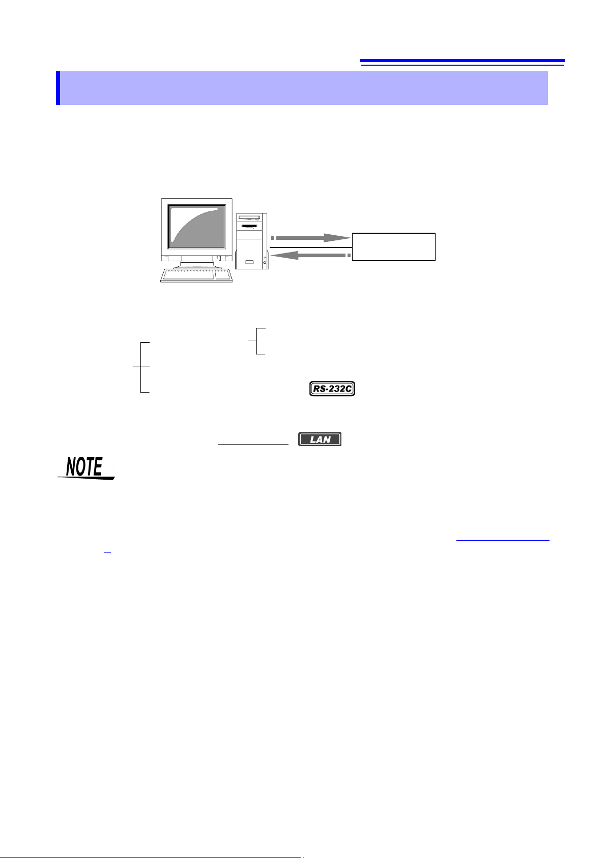
Messages are provided in the interface to control the Power Meter.
There are two types of messages: program messages that are sent from the controller (such as a computer) to the
Power Meter and response messages that are sent from the Power Meter to the controller.
There are also execution confirmation messages for synchronization with the controller in the RS-232C interface.
Message types are further categorized as follows.
Program Messages
Messages Response Messages
Execution Confirmation Messages
When issuing commands that contain data, make sure that the data is provided in the specified format.
When connecting via LAN, connect to TCP/IP port 3300.
Command Messages
Query Messages
During communication the Power Meter will enter the Remote state and the REMOTE Indicator on the unit will
turn ON.
When this occurs, all operation keys except for SHIFT(EXIT/LOCAL) will be disabled.
However, if the Power Meter is in the Local Lock Out state via GP-IB (GP-IB command LLO:Local Lock Out ->
P.11), the SHIFT(EXIT/LOCAL) Key will also be disabled. If this occurs, execute the GTL (Go To Local)
interface function or turn the Power Meter OFF and ON again to return to the Local state.
If the Power Meter enters the Remote state when on the settings screen, it will automatically change to the
measurement display.
PW3335A985-01

2
Message Format
Program Messages
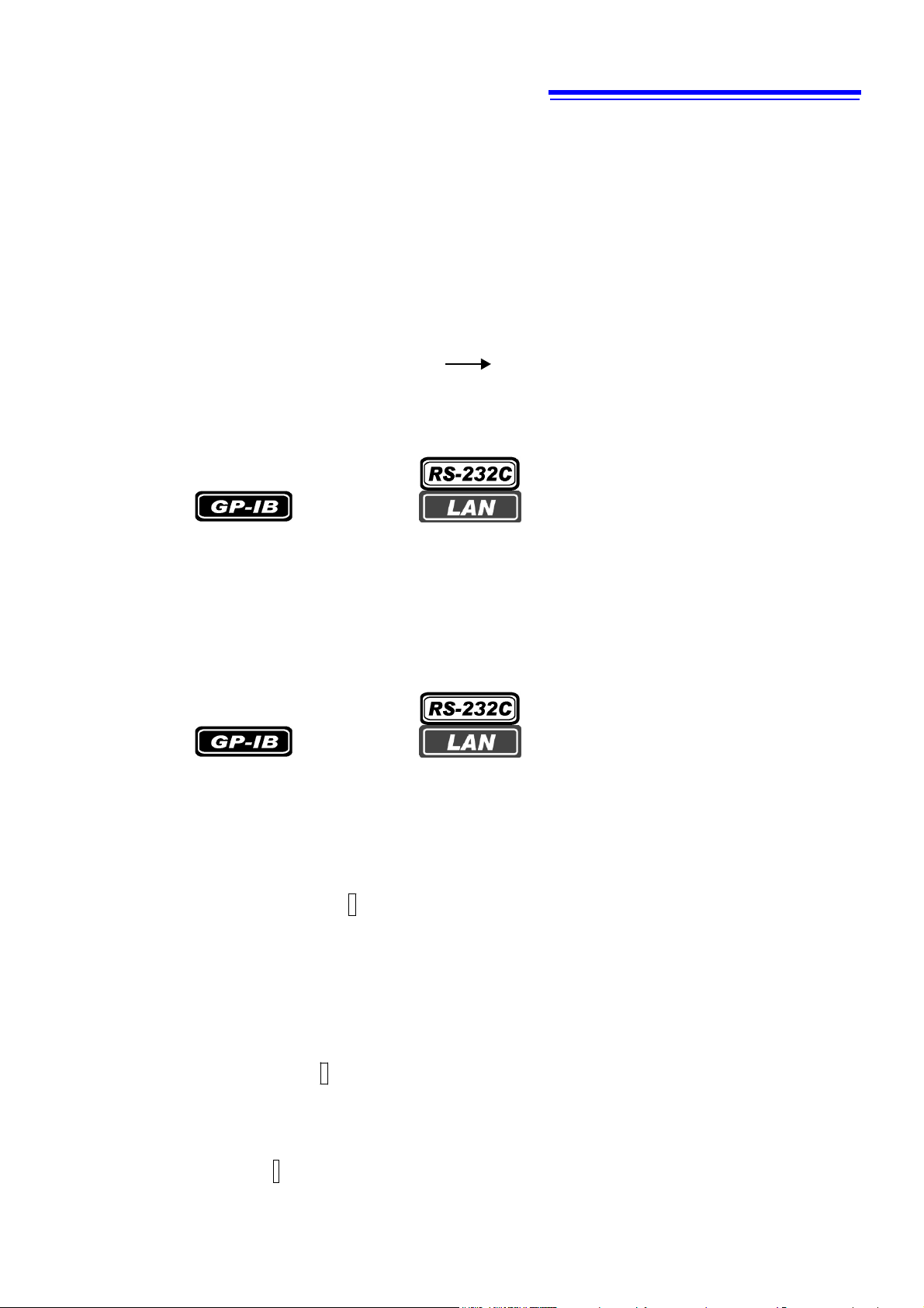
Program messages can be either Command Messages or Query Messages.
(1) Command Messages
Instructions to control the instrument, such as to change settings or reset
Example: Instruction to set the voltage range.
:VOLTAGE:RANGE 300
Header portion Space Data portion
(2) Query Messages
Requests for responses relating to results of operation or
measurement, or the state of instrument settings
Example: Request for the current measurement range
:VOLTAGE:RANGE?
See: "Headers (p. 2)", "Separators (p. 3)", "Data Formats (p.4)"
Response Messages
When a query message is received, its syntax is checked and a response message is generated.The :HEADer command determines whether headers are prefixed to response messages.
Header ON :VOLTAGE:RANGE 300
Header OFF 300
At power-on, Header ON is selected.
If an error occurs when a query message is received, no response message is generated for that query.
Command Syntax
Command names are chosen to mnemonically represent their function, and can be abbreviated. The full
command name is called the “long form”, and the abbreviated name is called the “short form”. The
command references in this manual indicate the short form in upper-case letters, extended to the long form
in lower case letters, although the commands are not case-sensitive in actual usage.
DISPLAY?
DISP?
DISPL?
DIS?
Response messages generated by the instrument are in long form and in upper case letters.
Headers
Headers must always be prefixed to program messages.
(1) Command Program Headers
There are three types of commands: Simple, Compound, and Standard.
• Headers for Simple Commands
This header type is a sequence of letters and digits.
:ESE0
• Headers for Compound Commands
These headers consist of multiple simple command type headers separated by colons ":".
:VOLTage:RANGE
Header portion Question mark
(The current voltage range is 300 V.)
OK ( long form
OK ( short form
Error
Error
)
)
PW3335A985-01
3
•
LF
•
CR+LF
•
EOI
•
LF
with an EOI
•
LF
•
CR+LF
•
LF
with an EOI
•
CR
+ LF
with an EOI (default)
•
LF
•
CR+LF (default)
• Headers for Standard Commands
This header type begins with an asterisk "*", indicating that it is a standard command defined by IEEE 488.2.
*RST
(2) Query Program Header
These commands are used to query the instrument about the results of operations, measured values, and the
current states of instrument settings.
As shown in the following examples, a query is formed by appending a question mark ? after a program header.
:HOLD?
:VOLTage:RANGe?
Characters within square brackets [ ] may be omitted.
Either form is valid
:MEASure[:NORMAL]:VALue? :MEASure:VALue?
Message Terminators
The instrument recognizes the following message terminators (delimiters):
Depending on the instrument's interface settings, the following can be selected as the terminator for response
messages.
For information on settings, see "Terminator Setting" (p. 111).
Separators
(1) Message Unit Separator
Multiple messages can be written in one line by separating them with semicolons ";".
:VOLTage:RANGe 300;:AVERaging 10
• When messages are combined in this way and if one command contains an error, all subsequent messages
up to the next terminator will be ignored.
(2) Header Separator
In a message consisting of both a header and data, the header is separated from the data by a space
“ ” (ASCII code 20H).
: VOLTage: RANGe 300
(3) Data Separator
In a message containing multiple data items, commas are required to separate the data items from one another.
:MEASure? U, I
PW3335A985-01

4
The instrument does not completely support IEEE 488.2. Use referenced data whenever possible.
Also be careful not to overflow the input buffer or output queue with a single command.
Data Formats
The instrument uses character data, decimal numeric data and character string data depending on the command.
(1) Character Data
Character data always begins with an alphabetic character, and subsequent characters may be either
alphabetic or numeric. Character data is not case-sensitive, although response messages from the instrument
are only upper case. When the command data portion contains <1/0/ON/OFF>, the operation will be the same
as when 0 is OFF and 1 is ON.
:HEADER OFF
(2) Decimal Numeric Data
Three formats are used for numeric data: NR1, NR2 and NR3. Numeric values may be signed or unsigned.
Unsigned numeric values are handled as positive values. Values exceeding the precision handled by the
instrument are rounded to the nearest valid digit or truncated.
NR1 Integer data (e.g.: +12, -23, 34)
•
NR2 Fixed-point data (e.g.: +1.23, -23.45, 3.456)
•
NR3 Floating-point exponential representation data (e.g.: +1.0E-2, -2.3E+4)
•
The term “NRf format” includes all three of the above numeric decimal formats.
The instrument accepts NRf format data. The format of response data is specified for each command, and the
data is sent in that format.
:AVERAGING 10
Compound Command Header Omission
When several commands having a common header are combined to form a compound command (for
example, :VOLTage:AUTO and :VOLTage:RANGe), if they are written together in sequence, the common portion
(here, :VOLTage:) can be omitted after its initial occurrence.
This common portion is called the “current path” (analogous to the path concept in computer file storage), and until
it is cleared, the interpretation of subsequent commands presumes that they share the same common portion.
This usage of the current path is shown in the following example:
Full expression
:VOLTage:AUTO OFF;:VOLTage:RANGe 300
Compacted expression
:VOLTage:AUTO OFF;RANGe 300
The current path allows you to abbreviate the next command.
The current path is cleared when the power is turned on, when reset by key input, by a colon “:” at the start of
a command, and when a message terminator is detected.
Standard command messages can be executed regardless of the current path. They have no effect upon the
current path.
A colon “:” is not required at the start of the header of a Simple or Compound command. However, to avoid
confusion with abbreviated forms and operating mistakes, we recommend always placing a colon at the start of
a header.
PW3335A985-01

5
• Power on
• Device clear
• Query error
Output Queue and Input Buffer
Output Queue
Response messages are stored in the output queue until read by the controller. The output queue is also cleared
in the following circumstances:
The output queue capacity of the instrument is 4,096 bytes. If response messages overflow the buffer, a query
error is generated and the output queue is cleared.
Input Buffer
The input buffer capacity of the instrument is 1,024 bytes.
If 1,024 bytes are allowed to accumulate in this buffer so that it becomes full, the GP-IB interface bus enters the
waiting state until space is cleared in the buffer.
The RS-232C and LAN interfaces will not accept data beyond 1,024 bytes.
Note: Ensure that the length of a single line never exceeds 1,024 bytes.
PW3335A985-01
6
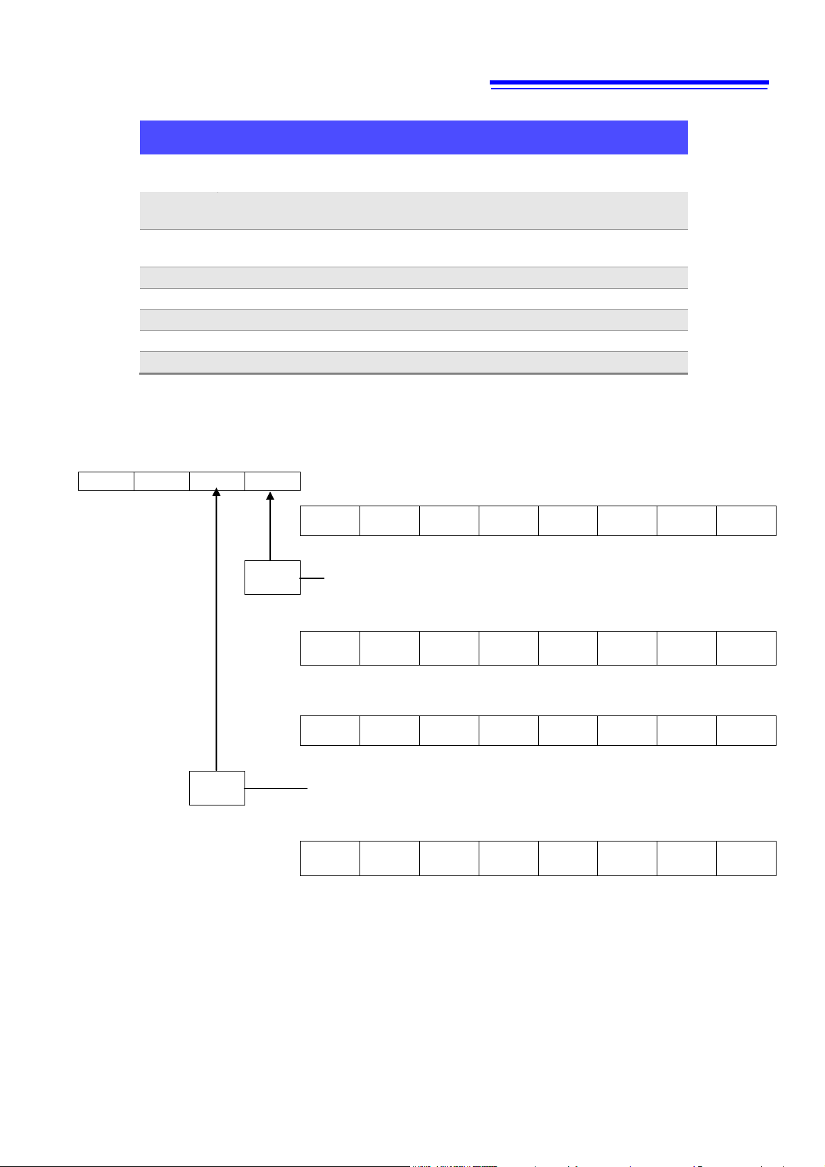
bit7 bit6 bit5
bit4
bit3
bit2 bit1 bit0
unused
SRQ
ESB
MAV
unused
unused
ESB1
ESB0
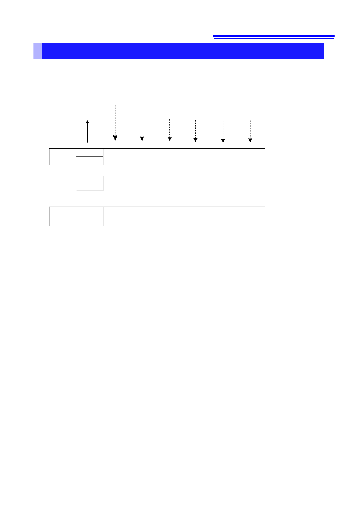
Status Byte Register
(STB)
MSS
↑ ↓ ↓ ↓
↓
Logical
sum
←& & &
&
↑ ↑ ↑
↑
bit7 bit6 bit5
bit4
bit3
bit2 bit1 bit0
unused
0
ESB
MAV
unused
unused
ESB1
ESB0
Service Request
Enable Register
(SRER)
Status Byte Register
The instrument uses the status model defined by the IEEE 488.2 standard for items related to serial polling
via the service request function.
Events are what trigger service requests.
Standard Event Register Description
Service Request Output Queue data information
SRQ occurrence Each of these bits correspond to a specific event register
Overview of Service Request Occurrence
The Status Byte Register contains information about the event registers and the output queue.
Required items are selected from this information by masking with the Service Request Enable
Register.
When any bit selected by the mask is set, bit 6 (MSS; the Master Summary Status) of the Status Byte
Register is also set, which generates an SRQ (Service Request) message and dispatches a service
request.
SRQs (Service Requests) can be used only with the GP-IB interface.
However, SRER setting (*SRE?) and STB read (*STB?) queries can be used even with the RS-232C
and LAN interfaces.
PW3335A985-01

7
Bit 7
unused
Bit 6
SRQ
Set to 1 when a service request is dispatched.
MSS
This is the logical sum of the other bits of the Status Byte Register.
Bit 5
ESB
Standard Event Status (logical sum) bit
This is the logical sum of the Standard Event Status Register.
Bit 4
MAV
Message available
Indicates that a message is present in the output queue.
Bit 3
unused
Bit 2
unused
Bit 1
ESB1
Event Summary (logical sum) bit 1
This is the logical sum of Event Status Register 1.
Bit 0
ESB0
Event Summary (logical sum) bit 0
This is the logical sum of Event Status Register 0.
Status Byte Register (STB)
During serial polling, the contents of the 8-bit Status Byte Register are sent from the instrument to the controller.
When any Status Byte Register bit enabled by the Service Request Enable Register has switched from 0 to 1, the
MSS bit becomes 1. Consequently, the SRQ bit is set to 1, and a service request is dispatched.
The SRQ bit is always synchronous with service requests, and is read and simultaneously cleared during serial
polling. Although the MSS bit is only read by an *STB? query, it is not cleared until a clear event is initiated by the
*CLS command.
Service Request Enable Register (SRER)
Setting a bit of this register to 1 enables the corresponding bit of the
Status Byte Register to be used.
PW3335A985-01

8
Bit 7
PON
Power-On Flag
Set to 1 when the power is turned on, or upon recovery from an outage.
Bit 6
URQ
User Request
unused
Bit 5
CME
Command error (The command to the message terminator is ignored.)
This bit is set to 1 when a received command contains a syntactic or semantic
error:
• Program header error
• Incorrect number of data parameters
• Invalid parameter format
• Received a command not supported by the instrument
Bit 4
EXE
Execution Error
This bit is set to 1 when a received command cannot be executed for some
reason.
• The specified data value is outside of the set range
• The specified data cannot be set (data format discrepancy)
• Execution is prevented by some other operation being performed
Bit 3
DDE
Device-dependent Error
This bit is set to 1 when a command cannot be executed due to some reason
other than a command error, a query error or an execution error.
• An internal error occurred and execution cannot be performed (error
displayed)
• A command was received that cannot be executed during a restricted
operation (integration, hold, etc.)
• When "o.r",”S.Err” or ”-----“ occurs and the error data is read by a *MEASure?
query.
Bit 2
QYE
Query Error (the output queue is cleared)
This bit is set to 1 when a query error is detected by the output queue control.
• When an attempt is made to read the output queue when the output queue is
empty (GP-IB only)
• When the data overflows the output queue
• When the next command is received while there is data in the output queue
• When there is a query after a *IDN? on the same line.
Bit 1
RQC
(unused)
Request Control
Bit 0
OPC
Operation Complete
This bit is set to 1 in response to an *OPC command.
• It indicates the completion of operations of all messages up to the *OPC
command
Event Registers
Standard Event Status Register (SESR)
The Standard Event Status Register is an 8-bit register.
If any bit in the Standard Event Status Register is set to 1(after masking by the Standard Event Status Enable
Register), bit 5 (ESB) of the Status Byte Register is set to 1.
See: “
Standard Event Status Enable Register (SESER)” (p.
The Standard Event Status Register is cleared in the following situations:
• When a *CLS command is executed
• When an event register query
• When the instrument is powered on
(
*ESR?) is executed
9)
PW3335A985-01
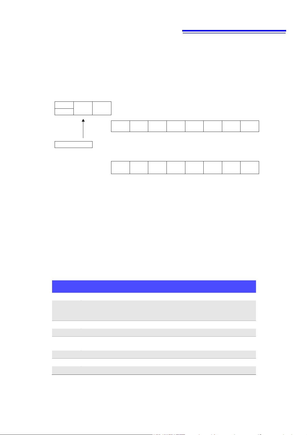
9
Status Byte Register (STB)
bit6 bit5
bit4
SRQ
ESB
MAV
MSS
Standard Event Status Register (SESR)
bit7 bit6
bit5
bit4
bit3
bit2 bit1 bit0
PON
URQ
CME
EXE
DDE
QYE
RQC
OPC
↓ ↓ ↓ ↓ ↓ ↓ ↓ ↓
Logical sum
← & & & & & & & &
↑ ↑ ↑ ↑ ↑ ↑ ↑ ↑
bit7 bit6
bit5
bit4
bit3
bit2 bit1 bit0
PON
URQ
CME
EXE
DDE
QYE
RQC
OPC
Standard Event Status Enable Register (SESER)
Event Status Register 0 (ESR0)
Bit 7
DataSet
Data updated.
Bit 6
Change
Setting
Err
Data became invalid due to a hardware-related setting change.
(For example, immediately after the range was changed.)
Bit 5
SyncErr
A synchronization error occurred on ch1, ch2, or ch3.
Bit 4
IntegrateEnd
Integration has completed.
Bit 3
AVeraGe
update
Averaged data updated.
Bit 2
Current Protection
Instrument protection mode activated.
Bit 1
---
Unused.
Bit 0
Ext.Sync Error
Failed external synchronization for the data update.
Standard Event Status Enable Register (SESER)
Setting any bit of the Standard Event Status Enable Register to 1 enables access to the corresponding bit of the
Standard Event Status Register.
Standard Event Status Register (SESR) and Standard Event Status Enable Register (SESER)
Device-specific Event Status Registers (ESR0, and ESR1)
This instrument provides four Event Status Registers for controlling events.
Each event register is an 8-bit register.
When any bit in one of these Event Status Registers enabled by its corresponding Event Status Enable Register
is set to 1, the following happens:
• For Event Status Register 0, bit 0 (ESB0) of the Status Byte Register (STB) is set to 1.
• For Event Status Register 1, bit 1 (ESB1) of the Status Byte Register (STB) is set to 1.
Event Status Registers 0 through 1 are cleared in the following situations:
• When a *CLS command is executed
• When an Event Status Register query (
• When the instrument is powered on
:ESR0?
, or
:ESR1?
) is executed
PW3335A985-01
10
Status Byte Register (STB)
bit1 bit0
ESB1
ESB0
Event Status Register 0 (ESR0)
bit7 bit6 bit5
bit4
bit3
bit2 bit1 bit0
DS
CSE
SE
IE
AVG
HP
unused
ESE
↓ ↓ ↓ ↓ ↓ ↓ ↓
↓
Logical
sum
& & & & & & &
&
↑ ↑ ↑ ↑ ↑ ↑ ↑
↑
bit7 bit6 bit5
bit4
bit3
bit2 bit1 bit0
DS
CSE
SE
IE
AVG
HP
unused
ESE
Event Status Enable Register 0 (ESER0)
bit7 bit6 bit5
bit4
bit3
bit2 bit1 bit0
FOR
ODI
CODI
OI
OU
HP
HI
HU
↓ ↓ ↓ ↓ ↓ ↓ ↓
↓
Logical
sum
& & & & & & &
&
↑ ↑ ↑ ↑ ↑ ↑ ↑
↑
bit7 bit6 bit5
bit4
bit3
bit2 bit1 bit0
FOR1
ODI
CODI
OI
OU
HP
HI
HU
Event Status Enable Register 1 (ESER1)
Event Status Register 1 (ESR1)
Bit 7
Frequency
Out of Range
The frequency(voltage or current) is invalid.
Bit 6
Over
DataIntegrate
A peak overflow of voltage or current occurred in the active power
integration value.
Bit 5
CurrentOver
DataIntegrate
A peak overflow of current occurred in the current integration
value.
Bit 4
Over-I
A peak overflow occurred in the current input.
Bit 3
Over-U
A peak overflow occurred in the voltage input.
Bit 2
High-P
The active power is over range.
Bit 1
High-I
The current is over range.
Bit 0
High-U
The voltage is over range.
Event Status Register 0 to 1 (ESR0 to ESR1) and
Event Status Enable Register 0 to 1 (ESER0 to ESER1)
PW3335A985-01

11
Register
Read
Write
Status Byte Register
*STB?
-
Service Request Enable Register
*SRE?
*SRE
Standard Event Status Register
*ESR?
-
Standard Event Status Enable Register
*ESE?
*ESE
Event Status Register 0
:ESR0?
-
Event Status Enable Register 0
:ESE0?
:ESE0
Event Status Register 1
:ESR1?
-
Event Status Enable Register 1
:ESE1?
:ESE1
Command
Description
GTL
Go To Local
Changes the instrument from the Remote state to the Local
state.
LLO
Local Lock Out
Locks all keys on the instrument, including the Local Key.
DCL
Device CLear
Clears the input buffer and output queue.
SDC
Selected Device Clear
Clears the input buffer and output queue.
GET
Group Execute Trigger
Updates the displayed value while it is being held.
Register Reading and Writing
GP-IB Commands
The following commands can be used through interface functions.
PW3335A985-01
12
Initialization Method
Item
At
Power-on
System
Reset
*RST
Command
Device
Clear
(GP-IB only)
*CLS
Command
Factory
Default
GP-IB address
- - - - -
1
RS-232C setting (baud rate)
- - - - -
38400
LAN setting
- - - - -
*4
Device-specific functions (range,
etc.)
-
●
●
-
-
*4
Output Queue
●
●
- ● -
●
Input Buffer
●
●
- ● -
●
Status Byte Register
●
●
-
-*1
●*2
●
Event registers
●*3
●
-
-
●
●
Enable register
●
●
- - -
0
Current path
●
●
- ● -
●
Headers on/off
● ● ●
-
-
ON
Output items
● ● ●
*5,
Response message terminator
●
●
- - -
CR+LF
Response message separator
● ● ●
-
-
;
*1. Only the MAV bit (bit 4) is cleared.
*2. All bits except the MAV bit are cleared.
*3. Except the PON bit (bit 7).
*4. Refer to the user's manual for the instrument.
*5. See below.
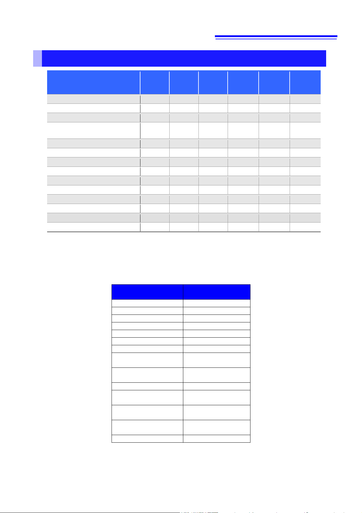
Measurement Item
Voltage (U)
○
Current (I)
○
Active power (P)
○
Apparent power (S)
○
Reactive power (Q)
○
Power factor (PF)
○
Phase angle (DEG)
○
Voltage frequency
(FREQU)
○
Current frequency
(FREQI)
○
Harmonic wave voltage
effective value (HU)
○ (first-order only)
Harmonic wave current
effective value (HU)
○ (first-order only)
Harmonic wave power
effective value (HU)
○ (first-order only)
Initialization Items
Output Item Initialization
Output for all items other than those listed above is OFF by default.
PW3335A985-01
13
Command
Execution time (excluding communication time and delays to the start of analysis)
*WAI
200ms or less
The other commands
10 ms or less
(150 ms)
(Priority given to measurement and
calculation processing)
(50 ms)
(200 ms) Display update rate: 5 times per second
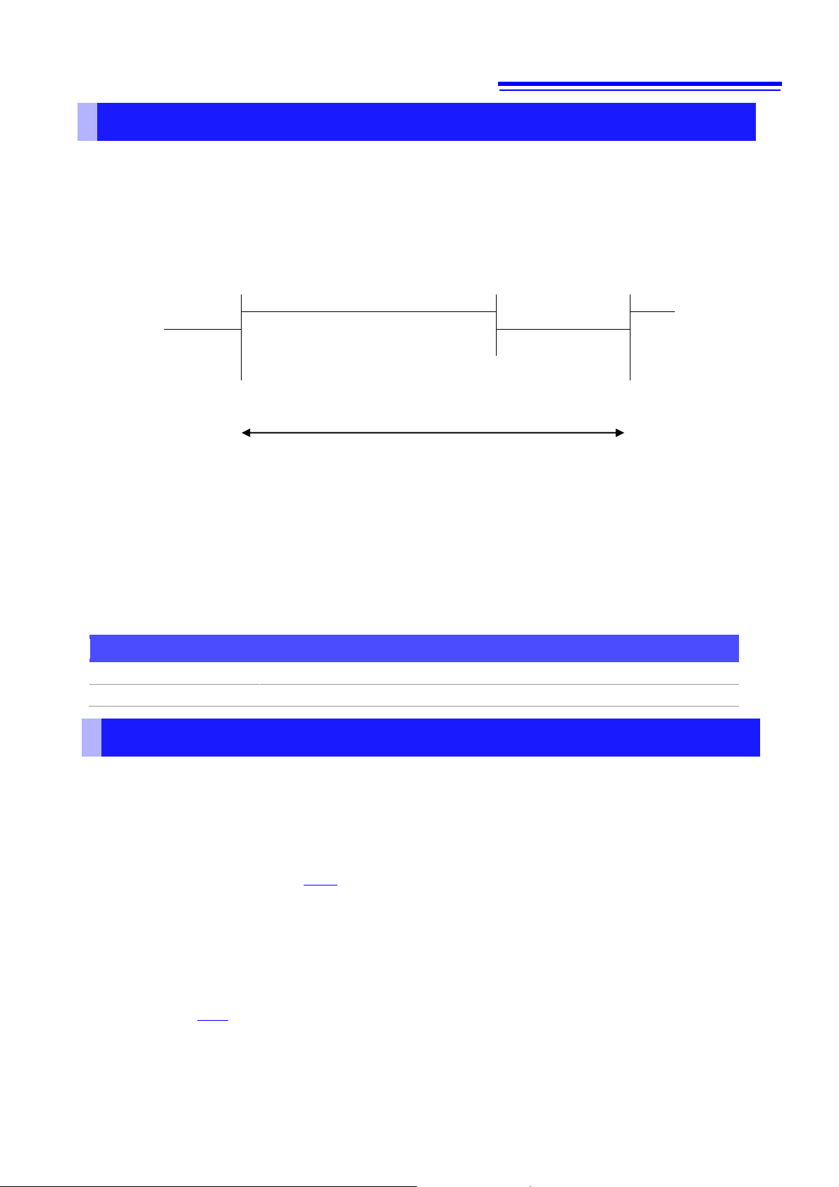
Command Execution Time
Command execution time indicates the time for analyzing and processing long form commands.
However, the command execution time for commands with data is the time described according to the data format
specified in the <data portion>, and for query commands it is the time when the header is ON.
The instrument performs measurements, calculations, and updates the display repeatedly in 200 ms cycles.
Measurements and calculations are given priority over command processing, and require a maximum of 150
ms. Therefore, a maximum delay of 150 ms may be encountered from the time a command is received until
analysis begins.
• Updating the display may be delayed if the analysis processing is not completed in time, even if the internal
processing time is met.
• All commands are sequential.
• When communicating with a controller, the time required to transfer the data must be added.
The amount of time required for the data transfer depends on the controller (communications).
The RS-232C transfer time for a starting bit, data length of 8, no parity bit, and a stop bit (10 bits total) with a baud
rate setting of N bps is calculated as follows:
Transfer Time T [1 character/second] = Baud Rate N [bps] / 10 [bits]
The measurement value is 11 characters so the time required to transfer one piece of data would be 11/T.
(Example) 9600 bps: 11 / (9600 / 10) = 11 ms (approximately)
• Wait a few moments after making any changes via setting commands to allow the measurements to stabilize.
Errors During Communications
An error occurs when messages are executed in the following cases:
• Command Error
When message syntax (spelling) is invalid
When the data format in a command or query is invalid
• Query Error
When the response message exceeds 4,000 bytes
When there is a query after an
• Execution Error
When invalid character or numeric data is present
• Device-dependent Error
When an error occurs during self-testing
When a restricted operation (such as changing the range) is attempted during an integration operation (when the
INTEGRATOR indicator is lit or flashing)
When a restricted operation (such as changing the range) is attempted during the Hold state
When the
Note:
A command error will always occur if a message is spelled incorrectly or if any data is present after a query.
When an error occurs with a query, no response message will be generated for that query.
*TRG command is executed in any state other than the Hold state
*IDN? query
PW3335A985-01

14
Message
Data Formats
(Response data for queries)
Description
Reference
Page
*CLS
Clears the event registers and the Status Byte
Register.
35
*ESE
0 to 255
Sets/Queries the Standard Event
Status Enable Register.
35
*ESE?
*ESR?
0 to 255
Queries the Standard Event Status Register.
35
*IDN?
<Manufacturer name>,
<Model name>,
<Model type>,
<Software version>
<Serial number>
Queries the Device ID.
33
*OPC
Sets bit 0 of the Standard Event Status Register
to 1 after an operation completes.
34
*OPC?
1
Queries execution completion.
34
*OPT?
Queries the device options.
33
*RST
Initializes the device.
33
*SRE
0 to 127
Sets/Queries the Service Request Enable
Register.
36
*SRE?
*STB?
0 to 127
Queries the Status Byte Register.
36
*TRG
Updates the display once.
36
*TST?
0 to 4
Initiates a self-test and queries the result.
34
*WAI
Waits until the next display update completes.
34
Message
Data Formats
(Response data for queries)
Description
Reference
Page
:ESE0
0 to 255
Sets/Queries Event Status Enable Register 0.
37
:ESE0?
:ESR0?
(0 to 255)
Queries Event Status Register 0.
37
:ESE1
0 to 255
Sets/Queries Event Status Enable Register 1.
37
:ESE1?
:ESR1?
(0 to 255)
Queries Event Status Register 1.
37
Message
2
The information in angled brackets < > represents the data format.
When the GP-IB interface is used, you can send an SRQ interrupt to the controller by setting the Event Status Register
and *SRE.
List
Standard Commands
Device-specific Commands (Event Registers)
PW3335A985-01

15
Message
Data Formats
(Response data for queries)
Description
Reference
Page
:AVERaging
1/2/5/10/25/50/100
Sets/Queries the number of times to
perform averaging.
38
:AVERaging?
:INTEGrate?
Queries the integration set time and the
integration state.
39
:INTEGrate:STATe
START/STOP/RESET
Sets/Queries the integration state.
39
:INTEGrate:STATe?
:INTEGrate:TIME
<Hour(NR1)>, <Minutes(NR1)>
Sets/Queries the integration time.
40
:INTEGrate:TIME?
:INTEGrate:AUTO
OFF/ON
Sets/Queries the auto-rage integration.
40
:INTEGrate:AUTO?
:HARMonic:ORDer:UPPer
<Order (2 to 50)>
Sets/Queries the upper limit order for
harmonic wave analysis.
40
:HARMonic:ORDer:UPPer?
:HOLD
OFF/ON/MAX/MIN/RESET
Sets/Queries the holds or releases the
display value.
41
:HOLD?
:ZEROadjust
Performs a zero adjustment.
41
:ZEROadjust
<Zero adjustment execution state>
Queries the zero adjustment execution
state.
41
:DEMAg
Performs a zero adjustment.
41
:DEMAg?
<Zero adjustment execution state>
Queries the zero adjustment execution
state.
:SYNC:CONTrol
<Synchronization control setting>
Sets/Queries the synchronization
control function.
42
:SYNC:CONTrol?
Message
Data Formats
(Response data for queries)
Description
Reference
Page
:VOLTage?
(<AUTO>,<Voltage Range>)
Queries the voltage range setting item (ch1 only).
42
:VOLTage:AUTO
ON/OFF
Sets (all channels) or queries (ch1 only)
the voltage automatic range.
42
:VOLTage:AUTO?
:VOLTage:RANGe
<Voltage Range (NR1)>
Sets (all channels) or queries (ch1 only)
the voltage range.
43
:VOLTage:RANGe?
:VOLTage:SELect:ALL?
ON/OFF
Sets whether to select all voltage ranges.
45
:VOLTage:SELect:U6V
ON/OFF
Sets/Queries whether to select the 6 V
voltage range.
45
:VOLTage:SELect:U6V?
:VOLTage:SELect:U15V
ON/OFF
Sets/Queries whether to select the 15 V
voltage range.
45
:VOLTage:SELect:U15V?
:VOLTage:SELect:U30V
ON/OFF
Sets/Queries whether to select the 30 V
voltage range.
45
:VOLTage:SELect:U30V?
:VOLTage:SELect:U60V
ON/OFF
Sets/Queries whether to select the 60 V
voltage range.
45
:VOLTage:SELect:U60V?
:VOLTage:SELect:U150V
ON/OFF
Sets/Queries whether to select the 150 V
voltage range.
45
:VOLTage:SELect:U150V?
:VOLTage:SELect:U300V
ON/OFF
Sets/Queries whether to select the 300 V
voltage range.
45
:VOLTage:SELect:U300V?
:VOLTage:SELect:U600V
ON/OFF
Sets/Queries whether to select the 600 V
voltage range.
45
:VOLTage:SELect:U600V?
:VOLTage:SELect:U1000V
ON/OFF
Sets/Queries whether to select the 1,000 V
voltage range.
45
:VOLTage:SELect:U1000V?
:VOLTage:SELect
<Voltage range
selection (NR1)>
Sets/Queries whether to select the voltage
range (3332-compatible).
45
:VOLTage:SELect?
Device-specific Commands (Measurement Settings)
Device-specific Commands (Voltage Range)
PW3335A985-01

16
Message
Data Formats
(Response data for queries)
Description
Reference
Page
:CURRent?
(<AUTO>, <Current Range>, ...)
Queries the current range setting item
(ch1 only).
46
:CURRent:AUTO
ON/OFF
Sets (all channels) or queries (ch1 only)
the current automatic range.
46
:CURRent:AUTO?
:CURRent:RANGe
<Current Range (NR1)>
Sets (all channels) or queries (ch1 only)
the current range.
47
:CURRent:RANGe?
:CURRent:SELect:ALL
ON/OFF
Sets whether to select all current
ranges.
47
:CURRent:SELect:I1mA
ON/OFF
Sets/Queries whether to select the 1 mA
current range (*1).
48
:CURRent:SELect:I1mA?
:CURRent:SELect:I2mA
ON/OFF
Sets/Queries whether to select the 2 mA
current range (*1).
48
:CURRent:SELect:I2mA?
:CURRent:SELect:I5mA
ON/OFF
Sets/Queries whether to select the 5 mA
current range (*1).
48
:CURRent:SELect:I5mA?
:CURRent:SELect:I10mA
ON/OFF
Sets/Queries whether to select the 10 mA
current range (*1).
48
:CURRent:SELect:I10mA?
:CURRent:SELect:I20mA
ON/OFF
Sets/Queries whether to select the 20 mA
current range (*1).
48
:CURRent:SELect:I20mA?
:CURRent:SELect:I50mA
ON/OFF
Sets/Queries whether to select the 50 mA
current range (*1).
48
:CURRent:SELect:I50mA?
:CURRent:SELect:I100mA
ON/OFF
Sets/Queries whether to select the 100 mA
current range (*1).
48
:CURRent:SELect:I200mA
ON/OFF
Sets/Queries whether to select the 200 mA
current range (*1).
48
:CURRent:SELect:I200mA?
:CURRent:SELect:I500mA
ON/OFF
Sets/Queries whether to select the 500 mA
current range (*1).
48
:CURRent:SELect:I500mA?
:CURRent:SELect:I1A
ON/OFF
Sets/Queries whether to select the 1 A
current range (*1).
48
:CURRent:SELect:I1A?
:CURRent:SELect:I2A
ON/OFF
Sets/Queries whether to select the 2 A
current range (*1).
48
:CURRent:SELect:I2A?
:CURRent:SELect:I5A
ON/OFF
Sets/Queries whether to select the 5 A
current range (*1).
48
:CURRent:SELect:I5A?
:CURRent:SELect:I10A
ON/OFF
Sets/Queries whether to select the 10 A
current range (*1).
48
:CURRent:SELect:I10A?
:CURRent:SELect:I20A?
ON/OFF
Sets/Queries whether to select the 20 A
current range (*1).
48
:CURRent:SELect
ON/OFF
Sets/queries whether to select the
current range (3332-compatible).
49
:CURRent:SELect?
:CURRent:EXTRange
<Clamp Current Range>
Sets (all channels) or queries (ch1 only)
the current range (current sensor).
50
:CURRent:EXTRange?
:CURRent:SELect:C1A
ON/OFF
Sets or queries whether to select the 1 A
current sensor range.
48
:CURRent:SELect:C1A?
:CURRent:SELect:C2A
ON/OFF
Sets or queries whether to select the 2 A
current sensor range.
48
:CURRent:SELect:C2A?
:CURRent:SELect:C5A?
ON/OFF
Sets or queries whether to select the 5 A
current sensor range.
48
:CURRent:TYPe
<Current Sensor Type>
Sets (all channels) or queries (ch1 only)
the current sensor type.
49
:CURRent:TYPe?
Device-specific Commands (Current Range)
*1: There is no abbreviated format available for the current range portion of the command (the “m” cannot be omitted).
PW3335A985-01

17
Message
Data Formats
(Response data for queries)
Description
Reference
Page
:FREQuency?
<Frequency Range (NR3)>
Queries the frequency range
(zero-crossing filter).
51
:FREQuency:RANGe
<Frequency Range (NR3)>
Sets or queries the frequency range
(zero-crossing filter).
51
:FREQuency:RANGe?
Message
Data Formats
(Response data for queries)
Description
Reference
Page
:SOURce
<Synchronization Source>
Sets (all channels) or queries (ch1 only) the
synchronization source.
52
:SOURce?
:SOURce:TIMEOut
0.1/1/10
Sets (all channels) or queries (ch1 only) the
synchronization timeout.
52
:SOURce:TIMEOut?
:SOURce:FILTer:LEVel:ALL
1~15
Sets all synchronization source detection levels.
52
:SOURce:FILTer:LEVel:U6V
1~15
Sets/Queries the voltage synchronization source
detection level.
53
:SOURce:FILTer:LEVel:U6V?
:SOURce:FILTer:LEVel:U15V
1~15
Sets/Queries the voltage synchronization source
detection level.
53
:SOURce:FILTer:LEVel:U15V?
:SOURce:FILTer:LEVel:U30V
1~15
Sets/Queries the voltage synchronization source
detection level.
53
:SOURce:FILTer:LEVel:U30V?
:SOURce:FILTer:LEVel:U60V
1~15
Sets/Queries the voltage synchronization source
detection level.
53
:SOURce:FILTer:LEVel:U60V?
:SOURce:FILTer:LEVel:U150V
1~15
Sets/Queries the voltage synchronization source
detection level.
53
:SOURce:FILTer:LEVel:U150V?
:SOURce:FILTer:LEVel:U300V
1~15
Sets/Queries the voltage synchronization source
detection level.
53
:SOURce:FILTer:LEVel:U300V?
:SOURce:FILTer:LEVel:U600V
1~15
Sets/Queries the voltage synchronization source
detection level.
53
:SOURce:FILTer:LEVel:U600V?
:SOURce:FILTer:LEVel:U1000V
1~15
Sets/Queries the voltage synchronization source
detection level.
53
:SOURce:FILTer:LEVel:U1000V?
:SOURce:FILTer:LEVel:I1mA
1~15
Sets/Queries the current synchronization source
detection level (*1).
53
:SOURce:FILTer:LEVel:I1mA?
:SOURce:FILTer:LEVel:I2mA
1~15
Sets/Queries the current synchronization source
detection level (*1).
53
:SOURce:FILTer:LEVel:I2mA?
:SOURce:FILTer:LEVel:I5mA
1~15
Sets/Queries the current synchronization source
detection level (*1).
53
:SOURce:FILTer:LEVel:I5mA?
:SOURce:FILTer:LEVel:I10mA
1~15
Sets/Queries the current synchronization source
detection level (*1).
53
:SOURce:FILTer:LEVel:I10mA?
:SOURce:FILTer:LEVel:I20mA
1~15
Sets/Queries the current synchronization source
detection level (*1).
53
:SOURce:FILTer:LEVel:I20mA?
:SOURce:FILTer:LEVel:I50mA
1~15
Sets/Queries the current synchronization source
detection level (*1).
53
:SOURce:FILTer:LEVel:I50mA?
:SOURce:FILTer:LEVel:I100mA
1~15
Sets/Queries the current synchronization source
detection level (*1).
53
:SOURce:FILTer:LEVel:I100mA?
:SOURce:FILTer:LEVel:I200mA
1~15
Sets/Queries the current synchronization source
detection level (*1).
53
:SOURce:FILTer:LEVel:I200mA?
:SOURce:FILTer:LEVel:I500mA
1~15
Sets/Queries the current synchronization source
detection level (*1).
53
:SOURce:FILTer:LEVel:I500mA?
:SOURce:FILTer:LEVel:I1A
1~15
Sets/Queries the current synchronization source
detection level.
53
:SOURce:FILTer:LEVel:I1A?
:SOURce:FILTer:LEVel:I2A
1~15
Sets/Queries the current synchronization source
detection level.
53
:SOURce:FILTer:LEVel:I2A?
:SOURce:FILTer:LEVel:I5A
1~15
Sets or queries the current synchronization
53
Device-specific Commands (Frequency Range [Zero-crossing Filter])
The frequency range and zero-crossing filter settings are linked.
Device-specific Commands (Synchronization Source)
PW3335A985-01

18
:SOURce:FILTer:LEVel:I5A?
source detection level.
:SOURce:FILTer:LEVel:I10A
1~15
Sets or queries the current synchronization
source detection level.
53
:SOURce:FILTer:LEVel:I10A?
:SOURce:FILTer:LEVel:I20A
1~15
Sets or queries the current synchronization
source detection level.
53
:SOURce:FILTer:LEVel:I20A?
:SOURce:FILTer:LEVel:C1A
1~15
Sets or queries the current (external sensor)
synchronization source detection level.
54
:SOURce:FILTer:LEVel:C1A?
:SOURce:FILTer:LEVel:C2A
1~15
Sets or queries the current (external sensor)
synchronization source detection level.
54
:SOURce:FILTer:LEVel:C2A?
:SOURce:FILTer:LEVel:C5A
1~15
Sets or queries the current (external sensor)
synchronization source detection level.
54
:SOURce:FILTer:LEVel:C5A?
Message
Data Formats
(Response data for queries)
Description
Reference
Page
:SCALe?
(<VT Ratio>, <CT Ratio>)
Queries
the VT and CT ratios.
55
:SCALe:VT
<VT Ratio (NRf)>
Sets or queries
the VT ratio.
55
:SCALe:VT?
:SCALe:CT
<CT Ratio (NRf)>
Sets or queries
the CT ratio.
55
:SCALe:CT?
*1: There is no abbreviated format available for the current range portion of the command (the “m” in “1 mA” and similar
text cannot be omitted).
Device-specific Commands (VT/CT Ratio)
PW3335A985-01

19
Message
Data Formats
(Response data for queries)
Description
Reference
Page
:AOUT?
Queries (D/A1 output items only)
D/A output items.
56
:AOUT:ITEM:DA1
<Output Item>
Sets/Queries the D/A1 terminal output item.
56
:AOUT:ITEM:DA1?
:AOUT:ITEM:DA2
<Output Item>
Sets/Queries the D/A2 terminal output item.
56
:AOUT:ITEM:DA2?
:AOUT:ITEM:DA3
<Output Item>
Sets/Queries the D/A3 terminal output item.
56
:AOUT:ITEM:DA3?
:AOUT:ITEM:DA4
<Output Item>
Sets/Queries the D/A4 terminal output item.
56
:AOUT:ITEM:DA4?
:AOUT:ITEM:DA5
<Output Item>
Sets/Queries the D/A5 terminal output item.
56
:AOUT:ITEM:DA5?
:AOUT:ITEM:DA6
<Output Item>
Sets/Queries the D/A6 terminal output item.
56
:AOUT:ITEM:DA6?
:AOUT:ITEM:DA7
<Output Item>
Sets/Queries the D/A7terminal output item.
56
:AOUT:ITEM:DA7
:AOUT:IRANge:DA1
<Integrated value current
range (NR2)>
Sets/Queries the current range selected output
item when outputting the D/A1 terminal
integrated value.
57
:AOUT: IRANge:DA1?
:AOUT:IRANge:DA2
<Integrated value current
range (NR2)>
Sets/Queries the current range selected output
item when outputting the D/A2 terminal
integrated value.
57
:AOUT: IRANge:DA2
:AOUT:IRANge:DA3
<Integrated value current
range (NR2)>
Sets/Queries the current range selected output
item when outputting the D/A3 terminal
integrated value.
57
:AOUT: IRANge:DA3?
:AOUT:IRANge:DA4
<Integrated value current
range (NR2)>
Sets/Queries the current range selected output
item when outputting the D/A4 terminal
integrated value.
57
:AOUT: IRANge:DA4?
:AOUT:IRANge:DA5
<Integrated value current
range (NR2)>
Sets/Queries the current range selected output
item when outputting the D/A5 terminal
integrated value.
57
:AOUT: IRANge:DA5?
:AOUT:IRANge:DA6
<Integrated value current
range (NR2)>
Sets/Queries the current range selected output
item when outputting the D/A6 terminal
integrated value.
57
:AOUT: IRANge:DA6?
:AOUT:IRANge:DA7
<Integrated value current
range (NR2)>
Sets/Queries the current range selected output
item when outputting the D/A7 terminal
integrated value.
57
:AOUT: IRANge:DA7?
Device-specific Commands (D/A Output)
PW3335A985-01

20
Message ([ ]: Can be omitted)
Data Formats
(Response data for queries)
Description
Reference
Page
:DISPlay[:NORMal]
(<Display a>, <Display b>,
<Display c>, <Display d>)
Sets/Queries instrument display items (a)
through (d).
62
:DISPlay[:NORMal]?
:DISPlay:NORMal:A
<Display a>
Sets/Queries instrument display item (a).
62
:DISPlay:NORMal:A?
:DISPlay:NORMal:B
<Display b>
Sets/Queries instrument display item (b).
62
:DISPlay:NORMal:B?
:DISPlay:NORMal:C
<Display c>
Sets/Queries instrument display item (c).
62
:DISPlay:NORMal:C?
:DISPlay:NORMal:D
<Display d>
Sets/Queries instrument display item (d).
62
:DISPlay:NORMal:D?
:DISPlay:MODE
<Display Specification>
Sets/Queries the instrument display mode
(normal/harmonic wave).
66
:DISPlay:MODE?
:DISPlay:HARMonic:ORDer
<Harmonic Wave Order
0 to 50>
Sets/Queries the display order for harmonic
wave order common display.
66
:DISPlay:HARMonic:ORDer?
:DISPlay:HARMonic:B:ITEM
<Harmonic Wave
Display Item>
Sets/Queries the display item (b) for
harmonic wave order common display.
66
:DISPlay:HARMonic:B:ITEM?
:DISPlay:HARMonic:C:ITEM
<Harmonic Wave
Display Item>
Sets/Queries the display item (c) for
harmonic wave order common display.
66
:DISPlay:HARMonic:C:ITEM?
:DISPlay:HARMonic:D:ITEM
<Harmonic Wave
Display Item>
Sets/Queries the display item (d) for
harmonic wave order common display.
66
:DISPlay:HARMonic:D:ITEM?
:DISPlay:HORDerSel:A:ORDer
<Harmonic Wave Order
0 to 50>
Display order (a) for harmonic wave order
individual display.
67
:DISPlay:HORDerSel:A:ORDer?
:DISPlay:HORDerSel:A:ITEM
<Harmonic Wave
Display Item>
Display item (a) for harmonic wave order
individual display.
67
:DISPlay:HORDerSel:A:ITEM?
:DISPlay:HORDerSel:B:ORDer
<Harmonic Wave Order
0 to 50>
Display order (b) for harmonic wave order
individual display.
67
:DISPlay:HORDerSel:B:ORDer?
:DISPlay:HORDerSel:B:ITEM
<Harmonic Wave
Display Item>
Display item (b) for harmonic wave order
individual display.
67
:DISPlay:HORDerSel:B:ITEM?
:DISPlay:HORDerSel:C:ORDer
<Harmonic Wave Order
0 to 50>
Display order (c) for harmonic wave order
individual display.
67
:DISPlay:HORDerSel:C:ORDer?
:DISPlay:HORDerSel:C:ITEM
<Harmonic Wave
Display Item>
Display item (c) for harmonic wave order
individual display.
67
:DISPlay:HORDerSel:C:ITEM?
:DISPlay:HORDerSel:D:ORDer
<Harmonic Wave Order
0 to 50>
Display order (d) for harmonic wave order
individual display.
67
:DISPlay:HORDerSel:D:ORDer?
:DISPlay:HORDerSel:D:ITEM
<Harmonic Wave
Display Item>
Display item (d) for harmonic wave order
individual display.
67
:DISPlay:HORDerSel:D:ITEM?
Device-specific Commands (Instrument Display Settings)
PW3335A985-01

21
Message ([ ]: Can be omitted)
Data Formats
(Response data
for queries)
Description
Reference
Page
:MEASure[:POWer]?
:MEASure[:NORMal]:VALue?
<Measurement Item 1> ...
Maximum 180
Queries measurement
data.
68
:MEASure:ITEM:ALLClear
Turns OFF all output items
(including harmonic wave).
75
:MEASure[:NORMal]:ITEM?
Queries output items.
75
:DATAout:ITEM(?)
(<Output Item 1>,
<Output Item 2>)
“:MEASure?” query output
specification
(3332-compatible)
76
:MEASure[:NORMAL]:ITEM:STATus:INST(?)
:MEASure[:NORMAL]:ITEM:STATus:MAXmin(?)
<Output Item 0/1>
“:MEASure?” query
Set/Query
the measurement status
output.
77
:MEASure[:NORMAL]:ITEM:U:ALL
:MEASure[:NORMAL]:ITEM:U:CH1(?)
<Output Item
(Rectification Method)>
“:MEASure?” query
Sets/Queries
the voltage (instantaneous
value) data output.
78
:MEASure[:NORMAL]:ITEM:U_MAX:ALL
:MEASure[:NORMAL]:ITEM:U_MAX:CH1(?)
<Output Item
(Rectification Method)>
“:MEASure?” query
Sets/Queries the voltage
(maximum value) data
output.
78
:MEASure[:NORMAL]:ITEM:U_MIN:ALL
:MEASure[:NORMAL]:ITEM:U_MIN:CH1(?)
<Output Item
(Rectification Method)>
“:MEASure?” query
Sets/Queries the voltage
(minimum value) data
output.
78
:MEASure[:NORMAL]:ITEM:I:ALL
:MEASure[:NORMAL]:ITEM:I:CH1(?)
<Output Item
(Rectification Method)>
“:MEASure?” query
Sets/Queries the current
(instantaneous value) data
output.
78
:MEASure[:NORMAL]:ITEM:I_MAX:ALL
:MEASure[:NORMAL]:ITEM:I_MAX:CH1(?)
<Output Item
(Rectification Method)>
“:MEASure?” query
Sets/Queries the current
(maximum value) data
output.
78
:MEASure[:NORMAL]:ITEM:I_MIN:ALL
:MEASure[:NORMAL]:ITEM:I_MIN:CH1(?)
<Output Item
(Rectification Method)>
“:MEASure?” query
Sets/Queries the current
(minimum value)
data output.
78
:MEASure[:NORMAL]:ITEM:P:ALL
:MEASure[:NORMAL]:ITEM:P:CH1(?)
<Output Item
(Rectification Method)>
“:MEASure?” query
Sets/Queries the active
power (instantaneous
value) data output.
79
:MEASure[:NORMAL]:ITEM:P_MAX:ALL
:MEASure[:NORMAL]:ITEM:P_MAX:CH1(?)
<Output Item
(Rectification Method)>
“:MEASure?” query
Sets/Queries the active
power (maximum value)
data output.
79
:MEASure[:NORMAL]:ITEM:P_MIN:ALL
:MEASure[:NORMAL]:ITEM:P_MIN:CH1(?)
<Output Item
(Rectification Method)>
“:MEASure?” query
Sets/Queries the active
power (minimum value)
data output.
79
Device-specific Commands (Measurement Value Output)
Note: :MEASure[:NORMAL]:ITEM:U:CH1(?) → Setting Command:MEASure[:NORMAL]:ITEM:U:CH1
Query :MEASure[:NORMAL]:ITEM:U:CH1?
PW3335A985-01

22
Message ([ ]: Can be omitted)
Data Formats
(Response data
for queries)
Description
Reference
Page
:MEASure[:NORMAL]:ITEM:S:ALL
:MEASure[:NORMAL]:ITEM:S:CH1(?)
<Output Item
(Rectification Method)>
“:MEASure?” query
Sets/Queries the apparent
power (instantaneous
value) data output.
79
:MEASure[:NORMAL]:ITEM:S_MAX:ALL
:MEASure[:NORMAL]:ITEM:S_MAX:CH1(?)
<Output Item
(Rectification Method)>
“:MEASure?” query
Sets/Queries the apparent
power (maximum value)
data output.
79
:MEASure[:NORMAL]:ITEM:S_MIN:ALL
:MEASure[:NORMAL]:ITEM:S_MIN:CH1(?)
<Output Item
(Rectification Method)>
“:MEASure?” query
Sets/Queries the apparent
power (minimum value)
data output.
79
:MEASure[:NORMAL]:ITEM:Q:ALL
:MEASure[:NORMAL]:ITEM:Q:CH1(?)
<Output Item
(Rectification Method)>
“:MEASure?” query
Sets/Queries the reactive
power (instantaneous
value) data output.
80
:MEASure[:NORMAL]:ITEM:Q_MAX:ALL
:MEASure[:NORMAL]:ITEM:Q_MAX:CH1(?)
<Output Item
(Rectification Method)>
“:MEASure?” query
Sets/Queries the reactive
power (maximum value)
data output.
80
:MEASure[:NORMAL]:ITEM:Q_MIN:ALL
:MEASure[:NORMAL]:ITEM:Q_MIN:CH1(?)
<Output Item
(Rectification Method)>
“:MEASure?” query
Sets/Queries the reactive
power (minimum value)
output data.
80
:MEASure[:NORMAL]:ITEM:PF:ALL
:MEASure[:NORMAL]:ITEM:PF:CH1(?)
<Output Item
(Rectification Method)>
“:MEASure?” query
Sets/Queries the power
factor (instantaneous
value) data output.
80
:MEASure[:NORMAL]:ITEM:PF_MAX:ALL
:MEASure[:NORMAL]:ITEM:PF_MAX:CH1(?)
<Output Item
(Rectification Method)>
“:MEASure?” query
Sets/Queries the power
factor (maximum value)
data output.
80
:MEASure[:NORMAL]:ITEM:PF_MIN:ALL
:MEASure[:NORMAL]:ITEM:PF_MIN:CH1(?)
<Output Item
(Rectification Method)>
“:MEASure?” query
Sets/Queries the power
factor (minimum value)
data output.
80
:MEASure[:NORMAL]:ITEM:DEG:ALL
:MEASure[:NORMAL]:ITEM:DEG:CH1(?)
<Output Item
(Rectification Method)>
“:MEASure?” query
Sets/Queries the phase
angle (instantaneous
value) data output.
81
:MEASure[:NORMAL]:ITEM:DEG_MAX:ALL
:MEASure[:NORMAL]:ITEM:DEG_MAX:CH1(?)
<Output Item
(Rectification Method)>
“:MEASure?” query
Sets/Queries the phase
angle (maximum value)
data output.
81
:MEASure[:NORMAL]:ITEM:DEG_MIN:ALL
:MEASure[:NORMAL]:ITEM:DEG_MIN:CH1(?)
<Output Item
(Rectification Method)>
“:MEASure?” query
Sets/Queries the phase
angle (minimum value)
data output.
81
:MEASure[:NORMAL]:ITEM:FREQU:ALL
:MEASure[:NORMAL]:ITEM:FREQU:CH1(?)
<Output Setting 0/1>
“:MEASure?” query
Sets/Queries the voltage
frequency (instantaneous
value) data output.
81
:MEASure[:NORMAL]:ITEM:FREQU_MAX:ALL
:MEASure[:NORMAL]:ITEM:FREQU_MAX:CH1(?)
<Output Setting 0/1>
“:MEASure?” query
Sets/Queries the voltage
frequency (maximum
value) data output.
81
PW3335A985-01

23
Message ([ ]: Can be omitted)
Data Formats
(Response data
for queries)
Description
Reference
Page
:MEASure[:NORMAL]:ITEM:FREQU_MIN:ALL
:MEASure[:NORMAL]:ITEM:FREQU_MIN:CH1(?)
<Output Setting 0/1>
“:MEASure?” query
Sets/Queries the voltage
frequency (minimum value)
data output.
81
:MEASure[:NORMAL]:ITEM:FREQI:ALL
:MEASure[:NORMAL]:ITEM:FREQI:CH1(?)
<Output Setting 0/1>
“:MEASure?” query
Sets/Queries the current
frequency (instantaneous
value) data output.
82
:MEASure[:NORMAL]:ITEM:FREQI_MAX:ALL
:MEASure[:NORMAL]:ITEM:FREQI_MAX:CH1(?)
<Output Setting 0/1>
“:MEASure?” query
Sets/Queries the current
frequency (maximum
value) data output.
82
:MEASure[:NORMAL]:ITEM:FREQI_MIN:ALL
:MEASure[:NORMAL]:ITEM:FREQI_MIN:CH1(?)
<Output Setting 0/1>
“:MEASure?” query
Sets/Queries the current
frequency (minimum value)
data output.
82
:MEASure[:NORMAL]:ITEM:TIME(?)
(Data by current range during auto-range integration)
:MEASure[:NORMAL]:ITEM:TIME:I200mA(?)
:MEASure[:NORMAL]:ITEM:TIME:I500mA(?)
:MEASure[:NORMAL]:ITEM:TIME:I1A(?)
:MEASure[:NORMAL]:ITEM:TIME:I2A(?)
:MEASure[:NORMAL]:ITEM:TIME:I5A(?)
:MEASure[:NORMAL]:ITEM:TIME:I10A(?)
:MEASure[:NORMAL]:ITEM:TIME:I20A(?)
:MEASure[:NORMAL]:ITEM:TIME:BACKup(?)
<Output Setting 0/1>
“:MEASure?” query
Sets/Queries
the integration time
data output.
82
:MEASure[:NORMAL]:ITEM:IH:ALL
:MEASure[:NORMAL]:ITEM:IH:CH1(?)
(Data by current range during auto-range integration)
:MEASure[:NORMAL]:ITEM:IH:CH1:I200mA(?)
:MEASure[:NORMAL]:ITEM:IH:CH1:I500mA(?)
:MEASure[:NORMAL]:ITEM:IH:CH1:I1A(?)
:MEASure[:NORMAL]:ITEM:IH:CH1:I2A(?)
:MEASure[:NORMAL]:ITEM:IH:CH1:I5A(?)
:MEASure[:NORMAL]:ITEM:IH:CH1:I10A(?)
:MEASure[:NORMAL]:ITEM:IH:CH1:I20A(?)
:MEASure[:NORMAL]:ITEM:IH:CH1:BACKup(?)
<Output Item
(Rectification Method)>
“:MEASure?” query
Sets/Queries
the integration current (total
sum) data output.
83
:MEASure[:NORMAL]:ITEM:PIH:ALL
:MEASure[:NORMAL]:ITEM:PIH:CH1(?)
(Data by current range during auto-range integration)
:MEASure[:NORMAL]:ITEM:PIH:CH1:I200mA(?)
:MEASure[:NORMAL]:ITEM:PIH:CH1:I500mA(?)
:MEASure[:NORMAL]:ITEM:PIH:CH1:I1A(?)
:MEASure[:NORMAL]:ITEM:PIH:CH1:I2A(?)
:MEASure[:NORMAL]:ITEM:PIH:CH1:I5A(?)
:MEASure[:NORMAL]:ITEM:PIH:CH1:I10A(?)
:MEASure[:NORMAL]:ITEM:PIH:CH1:I20A(?)
:MEASure[:NORMAL]:ITEM:PIH:CH1:BACKup(?)
<Output Item
(Rectification Method)>
“:MEASure?” query
Sets/Queries the positive
integration current data
output.
84
PW3335A985-01

24
Message ([ ]: Can be omitted)
Data Formats
(Response data
for queries)
Description
Reference
Page
:MEASure[:NORMAL]:ITEM:MIH:ALL
:MEASure[:NORMAL]:ITEM:MIH:CH1(?)
(Data by current range during auto-range integration)
:MEASure[:NORMAL]:ITEM:MIH:CH1:I200mA(?)
:MEASure[:NORMAL]:ITEM:MIH:CH1:I500mA(?)
:MEASure[:NORMAL]:ITEM:MIH:CH1:I1A(?)
:MEASure[:NORMAL]:ITEM:MIH:CH1:I2A(?)
:MEASure[:NORMAL]:ITEM:MIH:CH1:I5A(?)
:MEASure[:NORMAL]:ITEM:MIH:CH1:I10A(?)
:MEASure[:NORMAL]:ITEM:MIH:CH1:I20A(?)
:MEASure[:NORMAL]:ITEM:MIH:CH1:BACKup(?)
<Output Item
(Rectification Method)>
“:MEASure?” query
Sets/Queries the negative
integration current data
output.
85
:MEASure[:NORMAL]:ITEM:WP:ALL
:MEASure[:NORMAL]:ITEM:WP:CH1(?)
(Data by current range during auto-range integration)
:MEASure[:NORMAL]:ITEM:WP:CH1:I200mA(?)
:MEASure[:NORMAL]:ITEM:WP:CH1:I500mA(?)
:MEASure[:NORMAL]:ITEM:WP:CH1:I1A(?)
:MEASure[:NORMAL]:ITEM:WP:CH1:I2A(?)
:MEASure[:NORMAL]:ITEM:WP:CH1:I5A(?)
:MEASure[:NORMAL]:ITEM:WP:CH1:I10A(?)
:MEASure[:NORMAL]:ITEM:WP:CH1:I20A(?)
:MEASure[:NORMAL]:ITEM:WP:CH1:BACKup(?)
<Output Item
(Rectification Method)>
“:MEASure?” query
Sets/Queries
the integration active power
(total sum) data output.
86
:MEASure[:NORMAL]:ITEM:PWP:ALL
:MEASure[:NORMAL]:ITEM:PWP:CH1(?)
(Data by current range during auto-range integration)
:MEASure[:NORMAL]:ITEM:PWP:CH1:I200mA(?)
:MEASure[:NORMAL]:ITEM:PWP:CH1:I500mA(?)
:MEASure[:NORMAL]:ITEM:PWP:CH1:I1A(?)
:MEASure[:NORMAL]:ITEM:PWP:CH1:I2A(?)
:MEASure[:NORMAL]:ITEM:PWP:CH1:I5A(?)
:MEASure[:NORMAL]:ITEM:PWP:CH1:I10A(?)
:MEASure[:NORMAL]:ITEM:PWP:CH1:I20A(?)
:MEASure[:NORMAL]:ITEM:PWP:CH1:BACKup(?)
<Output Item
(Rectification Method)>
“:MEASure?” query
Sets/Queries
the integration active power
(positive) data output.
87
:MEASure[:NORMAL]:ITEM:MWP:ALL
:MEASure[:NORMAL]:ITEM:MWP:CH1(?)
(Data by current range during auto-range integration)
:MEASure[:NORMAL]:ITEM:MWP:CH1:I200mA(?)
:MEASure[:NORMAL]:ITEM:MWP:CH1:I500mA(?)
:MEASure[:NORMAL]:ITEM:MWP:CH1:I1A(?)
:MEASure[:NORMAL]:ITEM:MWP:CH1:I2A(?)
:MEASure[:NORMAL]:ITEM:MWP:CH1:I5A(?)
:MEASure[:NORMAL]:ITEM:MWP:CH1:I10A(?)
:MEASure[:NORMAL]:ITEM:MWP:CH1:I20A(?)
:MEASure[:NORMAL]:ITEM:MWP:CH1:BACKup(?)
<Output Item
(Rectification Method)>
“:MEASure?” query
Sets/Queries
the integration active power
(negative) data output.
88
:MEASure[:NORMAL]:ITEM:UPK:ALL
:MEASure[:NORMAL]:ITEM:UPK:CH1(?)
<Output Setting 0/1>
“:MEASure?” query
Sets/Queries the voltage
waveform peak value
(instantaneous value) data
output.
89
PW3335A985-01

25
Message ([ ]: Can be omitted)
Data Formats
(Response data
for queries)
Description
Reference
Page
:MEASure[:NORMAL]:ITEM:UPK_MAX:ALL
:MEASure[:NORMAL]:ITEM:UPK_MAX:CH1(?)
<Output Setting 0/1>
“:MEASure?” query
Sets/Queries the voltage
waveform peak value
(maximum value) data
output.
89
:MEASure[:NORMAL]:ITEM:UPK_MIN:ALL
:MEASure[:NORMAL]:ITEM:UPK_MIN:CH1(?)
<Output Setting 0/1>
“:MEASure?” query
Sets/Queries the voltage
waveform peak value
(minimum value) data
output.
89
:MEASure[:NORMAL]:ITEM:IPK:ALL
:MEASure[:NORMAL]:ITEM:IPK:CH1(?)
<Output Setting 0/1>
“:MEASure?” query
Sets/Queries the current
waveform peak
(instantaneous value) data
output.
89
:MEASure[:NORMAL]:ITEM:IPK_MAX:ALL
:MEASure[:NORMAL]:ITEM:IPK_MAX:CH1(?)
<Output Setting 0/1>
“:MEASure?” query
Sets/Queries the current
waveform peak value
(maximum value) data
output.
89
:MEASure[:NORMAL]:ITEM:IPK_MIN:ALL
:MEASure[:NORMAL]:ITEM:IPK_MIN:CH1(?)
<Output Setting 0/1>
“:MEASure?” query
Sets/Queries the current
waveform peak value
(minimum value) data
output.
89
:MEASure[:NORMAL]:ITEM:MCR:ALL
:MEASure[:NORMAL]:ITEM:MCR:CH1(?)
<Output Setting>
“:MEASure?” query
Sets/Queries the Maximum
Current Ratio
(instantaneous value) data
output.
90
:MEASure[:NORMAL]:ITEM:MCR_MAX:ALL
:MEASure[:NORMAL]:ITEM:MCR_MAX:CH1(?)
<Output Setting>
“:MEASure?” query
Sets/Queries the Maximum
Current Ratio
(maximum value) data
output.
90
:MEASure[:NORMAL]:ITEM:MCR_MIN:ALL
:MEASure[:NORMAL]:ITEM:MCR_MIN:CH1(?)
<Output Setting>
“:MEASure?” query
Sets/Queries the Maximum
Current Ratio
(minimum value) data
output.
90
:MEASure[:NORMAL]:ITEM:UCFactor:ALL
:MEASure[:NORMAL]:ITEM:UCFactor:CH1(?)
<Output Setting 0/1>
“:MEASure?” query
Sets/Queries the voltage
crest factor (instantaneous
value) data output.
90
:MEASure[:NORMAL]:ITEM:UCF_MAX:ALL
:MEASure[:NORMAL]:ITEM:UCF_MAX:CH1(?)
<Output Setting 0/1>
“:MEASure?” query
Sets/Queries the voltage
crest factor (maximum
value) data output.
90
:MEASure[:NORMAL]:ITEM:UCF_MIN:ALL
:MEASure[:NORMAL]:ITEM:UCF_MIN:CH1(?)
<Output Setting 0/1>
“:MEASure?” query
Sets/Queries the voltage
crest factor (minimum
value) data output.
90
:MEASure[:NORMAL]:ITEM:ICFactor:ALL
:MEASure[:NORMAL]:ITEM:ICFactor:CH1(?)
<Output Setting 0/1>
“:MEASure?” query
Sets/Queries the current
crest factor (instantaneous
value) data output.
91
PW3335A985-01

26
Message ([ ]: Can be omitted)
Data Formats
(Response data
for queries)
Description
Reference
Page
:MEASure[:NORMAL]:ITEM:ICF_MAX:ALL
:MEASure[:NORMAL]:ITEM:ICF_MAX:CH1(?)
<Output Setting 0/1>
“:MEASure?” query
Sets/Queries the current
crest factor (maximum
value) data output.
91
:MEASure[:NORMAL]:ITEM:ICF_MIN:ALL
:MEASure[:NORMAL]:ITEM:ICF_MIN:CH1(?)
<Output Setting 0/1>
“:MEASure?” query
Sets/Queries the current
crest factor (minimum
value) data output.
91
:MEASure[:NORMAL]:ITEM:ITAVerage:ALL
:MEASure[:NORMAL]:ITEM:ITAVerage:CH1(?)
(Data by current range during auto-range integration)
:MEASure[:NORMAL]:ITEM:ITAVerage:CH1:I200mA(?)
:MEASure[:NORMAL]:ITEM:ITAVerage:CH1:I500mA(?)
:MEASure[:NORMAL]:ITEM:ITAVerage:CH1:I1A(?)
:MEASure[:NORMAL]:ITEM:ITAVerage:CH1:I2A(?)
:MEASure[:NORMAL]:ITEM:ITAVerage:CH1:I5A(?)
:MEASure[:NORMAL]:ITEM:ITAVerage:CH1:I10A(?)
:MEASure[:NORMAL]:ITEM:ITAVerage:CH1:I20A(?)
:MEASure[:NORMAL]:ITEM:ITAVerage:CH1:BACKup(?)
<Output Item
(Rectification Method)>
“:MEASure?” query
Sets/Queries
the time average current
data output.
92
:MEASure[:NORMAL]:ITEM:PTAVerage:ALL
:MEASure[:NORMAL]:ITEM:PTAVerage:CH1(?)
(Data by current range during auto-range integration)
:MEASure[:NORMAL]:ITEM:PTAVerage:CH1:I200mA(?)
:MEASure[:NORMAL]:ITEM:PTAVerage:CH1:I500mA(?)
:MEASure[:NORMAL]:ITEM:PTAVerage:CH1:I1A(?)
:MEASure[:NORMAL]:ITEM:PTAVerage:CH1:I2A(?)
:MEASure[:NORMAL]:ITEM:PTAVerage:CH1:I5A(?)
:MEASure[:NORMAL]:ITEM:PTAVerage:CH1:I10A(?)
:MEASure[:NORMAL]:ITEM:PTAVerage:CH1:I20A(?)
:MEASure[:NORMAL]:ITEM:PTAVerage:CH1:BACKup(?)
<Output Item
(Rectification Method)>
“:MEASure?” query
Sets/Queries
the time average active
power data output.
93
:MEASure[:NORMAL]:ITEM:URF:ALL
:MEASure[:NORMAL]:ITEM:URF:CH1(?)
<Output Setting 0/1>
“:MEASure?” query
Sets/Queries the voltage
ripple factor (instantaneous
value) data output.
93
:MEASure[:NORMAL]:ITEM:URF_MAX:ALL
:MEASure[:NORMAL]:ITEM:URF_MAX:CH1(?)
<Output Setting 0/1>
“:MEASure?” query
Sets/Queries the voltage
ripple factor (maximum
value) data output.
93
:MEASure[:NORMAL]:ITEM:URF_MIN:ALL
:MEASure[:NORMAL]:ITEM:URF_MIN:CH1(?)
<Output Setting 0/1>
“:MEASure?” query
Sets/Queries the voltage
ripple factor (minimum
value) data output.
93
:MEASure[:NORMAL]:ITEM:IRF:ALL
:MEASure[:NORMAL]:ITEM:IRF:CH1(?)
<Output Setting 0/1>
“:MEASure?” query
Sets/Queries the current
ripple factor (instantaneous
value) data output.
94
:MEASure[:NORMAL]:ITEM:IRF_MAX:ALL
:MEASure[:NORMAL]:ITEM:IRF_MAX:CH1(?)
<Output Setting 0/1>
“:MEASure?” query
Sets/Queries the current
ripple factor (maximum
value) data output.
94
:MEASure[:NORMAL]:ITEM:IRF_MIN:ALL
:MEASure[:NORMAL]:ITEM:IRF_MIN:CH1(?)
<Output Setting 0/1>
“:MEASure?” query
Sets/Queries the current
ripple factor (minimum
value) data output.
94
PW3335A985-01

27
Message ([ ]: Can be omitted)
Data Formats
(Response data
for queries)
Description
Reference
Page
:MEASure[:NORMal]:ITEM:UTHD:ALL
:MEASure[:NORMal]:ITEM:UTHD:CH1(?)
<Output Setting 0/1>
“:MEASure?” query
Sets/Queries the total
harmonic wave voltage
distortion factor
(instantaneous value) data
output.
94
:MEASure[:NORMal]:ITEM:UTHD_MAX:ALL
:MEASure[:NORMal]:ITEM:UTHD_MAX:CH1(?)
<Output Setting 0/1>
“:MEASure?” query
Sets/Queries the total
harmonic wave voltage
distortion factor (maximum
value) data output.
94
:MEASure[:NORMal]:ITEM:UTHD_MIN:ALL
:MEASure[:NORMal]:ITEM:UTHD_MIN:CH1(?)
<Output Setting 0/1>
“:MEASure?” query
Sets/Queries the total
harmonic wave voltage
distortion factor data
output.
94
:MEASure[:NORMal]:ITEM:ITHD:ALL
:MEASure[:NORMal]:ITEM:ITHD:CH1(?)
<Output Setting 0/1>
“:MEASure?” query
Sets/Queries the total
harmonic wave current
distortion factor
(instantaneous value) data
output.
95
:MEASure[:NORMal]:ITEM:ITHD_MAX:ALL
:MEASure[:NORMal]:ITEM:ITHD_MAX:CH1(?)
<Output Setting 0/1>
“:MEASure?” query
Sets/Queries the total
harmonic wave current
distortion factor (maximum
value) data output.
95
:MEASure[:NORMal]:ITEM:ITHD_MIN:ALL
:MEASure[:NORMal]:ITEM:ITHD_MIN:CH1(?)
<Output Setting 0/1>
“:MEASure?” query
Sets/Queries the total
harmonic wave current
distortion factor (minimum
value) data output.
95
PW3335A985-01

28
Message ([ ]: Can be omitted)
Data Formats
(Response data for queries)
Description
Reference
Page
:MEASure:HARMonic[:VALue]?
Harmonic wave measurement
data output.
96
:MEASure:HARMonic:ITEM:ALLClear
“:MEASure:HARMonic?”
Turns OFF all query output.
98
:MEASure:HARMonic:ITEM:LIST(?)
(<Output Item 1>,
<Output Item 2>,
<Output Item 3>,
<Output Item 4>,
<Output Item 5>,
<Output Item 6>)
“:MEASure:HARMonic?”query.
Sets/Queries output items.
99
:MEASure:HARMonic:ITEM:ORDer(?)
(<Lower Limit Order>,
<Upper Limit Order>,
<ODD/EVEN/ALL>)
Sets/Queries the output order
of ":MEASure:HARMonic?"
queries.
100
:MEASure:HARMonic:ITEM:STATus:INST(?)
:MEASure:HARMonic:ITEM:STATus:MAXmin(?)
<Output Setting 0/1>
“:MEASure:HARMonic?” query
Sets/Querys the measurement
status output
100
:MEASure:HARMonic:ITEM:U:ALL
:MEASure:HARMonic:ITEM:U:CH1(?)
<Output Setting 0/1>
“:MEASure:HARMonic?”
Sets/Queries the output of the
harmonic wave voltage
effective value output for the
above query.
101
:MEASure:HARMonic:ITEM:U_MAX:ALL
:MEASure:HARMonic:ITEM:U_MAX:CH1(?)
<Output Setting 0/1>
“:MEASure:HARMonic?”
Sets/Queries the output of the
harmonic wave voltage
effective value (maximum
value) output for the above
query.
101
:MEASure:HARMonic:ITEM:U_MIN:ALL
:MEASure:HARMonic:ITEM:U_MIN:CH1(?)
<Output Setting 0/1>
“:MEASure:HARMonic?”
Sets/Queries the output of the
harmonic wave voltage
effective value (minimum
value) output for the above
query.
101
:MEASure:HARMonic:ITEM:I:ALL
:MEASure:HARMonic:ITEM:I:CH1(?)
<Output Setting 0/1>
“:MEASure:HARMonic?”
Sets/Queries the output of the
harmonic wave current
effective value output for the
above query.
101
:MEASure:HARMonic:ITEM:I_MAX:ALL
:MEASure:HARMonic:ITEM:I_MAX:CH1(?)
<Output Setting 0/1>
“:MEASure:HARMonic?”
Sets/Queries the output of the
harmonic wave current
effective value (maximum
value) output for the above
query.
101
Device-specific Commands (Measurement Value Output Settings [Harmonic Wave])
Note: :MEASure:HARMonic:ITEM:U:CH1(?) → Setting Command :MEASure:HARMonic:ITEM:U:CH1
Query :MEASure:HARMonic:ITEM:U:CH1?
PW3335A985-01
 Loading...