

Hioki PW3335, PW3335-02, PW3335-01, PW3335-03, PW3335-04 Instruction Manual
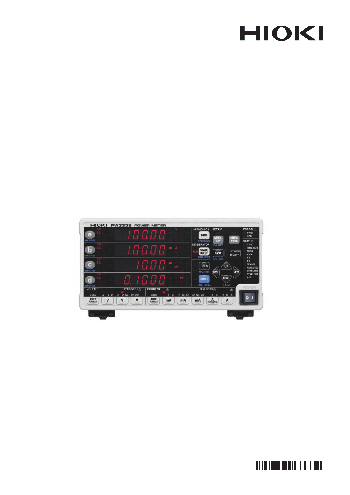
PW3335
PW3335-01,PW3335-02
PW3335-03,PW3335-04
POWER METER
Instruction Manual
Nov. 2015 Revised edition 1
PW3335A981-01 15-11H
EN
6 0 0 4 4 0 0 1 1


Contents
Contents
i
1
Introduction.....................................................1
Confirming Package Contents..................... ...2
Safety Information ..........................................3
Operating P re c a u tions.................. .. ... .............5
Chapter 1 Overview 11
1.1 Product Overview ...............................11
1.2 Feature s ................ .................... ......... 11
1.3 Names and Functions of Parts ...........13
1.4 Measurement Workflow .....................20
Chapter 2 Measurement
Preparations 25
2.1 Installation and Connection Procedures
........................................................... 25
2.2 Connecting the Measurement Lines ..26
Connecting the measurement lines ..........27
2.3 Connec t in g the Power Cord ...............3 3
2.4 Turning On the Instrument .................34
2.5 Performing Zero-adjustment ..............35
2.6 Activating Power to the Measurement
Lines ..................................................36
2.7 Turning Off the Instrument .................36
Chapter 3 Configuration and
Measurement 37
3.1 Pre-Measurement Inspection .............37
3.2 Configuring Settings ...........................38
3.2.1 Selecting the Current Input Method
........................................................ 38
3.2.2 Selecting Display Content ...............40
Selecting display parameters ....................40
Selecting the rectifier ................................42
3.2.3 Selecting the Voltage and Current
Ranges ............................................ 43
Selecting the desired range ......................43
PW3335A981-01
Automatically setting the range
(auto-range operation) ............................. 44
Skipping unnecessary rang es
(range select function) ............................. 46
3.2.4 Setting the Synchronization Source
(SYNC) ............................................48
3.2.5 Setting the Frequency Measurement
Range (Zero-cross filter) ............. .....50
Significance of changing the zero-cross
threshold level .......................................... 52
Setting the zero-cross filter’s
threshold level .......................................... 53
3.2.6 Setting the Timeout .........................54
3.2.7 Displaying Measured Values as an
Average (AVG: Averaging) ..............56
3.2.8 Setting the VT Ratio and CT Ratio ..58
Setting the VT ratio .................................. 59
Setting the CT ratio .................................. 60
3.3 Integration ..........................................61
Starting integration ................................... 64
Stopping integration ................................. 64
Starting integration while adding to previous
integrated values (additional integration) . 64
Canceling integration (resetting integrated
values) (DATA RESET) . ...... ....... ...... ....... 65
Performing integration after setting an
integration time (timer integration) ........... 65
Enabling auto-range integration ............... 67
Starting and stopping auto-range
integration ................................................ 68
Integration precautions ............................ 69
3.3.1 Integrated Value Display Format .....70
3.4 Viewing Harmonic Measured Values .71
3.4.1 Setting the Synchronization Source 71
3.4.2 Method for Displaying Harmonic
Measurement Parameters ...............71
3.4.3 Setting the Harmonic Analysis Order
Upper Limit ......................................76
3.4.4 About the HRM ERROR lamp .........77
3.5 Performing Synchronized Measurement
with Multiple Instruments ...................78
Connecting 2 instruments (PW3335) with a
synchronization cable .............................. 79
Configuring synchronized measurement . 80
3.6 External Control ..................................82
External control terminal
(EXT.CONTROL) ..................................... 82
Connecting wires to the external control
terminals .................................................. 84
2
3
4
5
6
7
8
9
10
11
12
付
録
索
引

ii
Contents
3.7 Usi ng D /A O u tp u t . ............. ... .............85
Connecting wires to D/A output terminals 87
3.7.1 Level Output, High-speed Level Output,
and Waveform Output .....................88
Setting the output parameter, rectifier, and
output method for D/A output channels ... 89
Setting D/A output when enabling
auto-range integration .............................. 91
Example uses .......................................... 94
Output voltage of level output .................. 95
Output voltage of waveform output .......... 99
3.8 Usi ng a Cu r re n t S e n sor ............. .. .....100
Before connecting a current sensor ....... 101
Connecting a TYPE.1 current sensor .... 102
Connecting a TYPE.2 current sensor .... 102
Setting external current sensor input ..... 104
Using an external CT ............................. 105
3.9 Other Functions ................................106
3.9.1 Fixing Display Values
(Display Hold) ................................106
Activating display hold ....... ...... .............. 106
Canceling the display hold state ............ 106
3.9.2 Displaying Maximum, and Minimum
Values (MAX/MIN) ......... ............. ...1 0 7
Switching the display among the maximum,
minimum, and instantaneous values ...... 107
Clearing maximum and minimum va lue s 108
3.9.3 Disabling Control Keys (Key Lock) 109
Enabling the key lock state .................... 109
Canceling the key lock state .................. 109
3.9.4 Initializing the Instrument
(System Reset) ..............................110
Factory Settings ..................................... 111
3.10 When warning lamp, o.r, or the
Unit Indicator Flashes .......................112
3.10.1 If the PEAK OVER U or PEAK OVER I
Lamp Lights Up ............. .. ..............1 1 2
3.10.2 I f the CURRENT
3.10.3 When o.r (over-range) Is Displayed 113
3.10.4 W hen the Unit Indicator Flashes ...114
Lamp Flashes .112
Setting the LAN’s default gateway ......... 119
Displaying the LAN’s MAC address ....... 120
Connecting the instrument to a computer
with a LAN cable .................................... 121
4.1.2 Using the RS-232C Interface
.............. ........................ ................ 123
Setting the RS-232C communications
speed ..................................................... 124
Connecting the RS-232C Cable ............. 125
4.1.3 Us in g t he G P -IB Interface ......... ... 127
Connecting the GP-IB Cable .................. 128
Setting the GP-IB address ..................... 129
4.2 Operating the Instrument from a PC's
Browser (LAN only) .......................... 130
Operating the instrument remote ly .........131
4.3 Canceling the Remote State
(Activating the Local State) .............. 133
Canceling the remote state .................... 133
Chapter 5 Specifications 135
5.1 Environmental and Safety
Specifications ................................... 135
5.2 General Specifications .....................136
5.3 Measurement specifications ............138
5.4 Functional Specifications .................154
5.5 Calculation Formulas Specifications 159
Chapter 6 Maintenance and
Service 163
6.1 Trouble Shooting .............................164
6.2 Error In d ic a tion ....... .. .............. .. ....... 166
Chapter 4 Connection to a PC
115
4.1 Configuring and Connecting the
Instrument ........................................116
4.1.1 U s in g th e LA N In t e rface ....... .. .......116
Setting the LAN’s IP address ................. 117
Setting the LAN’s subnet mask .............. 118
Appendix A1
Appendix 1 Detailed Specifications of Mea-
surement Items (Display Items)
................................................A1
Appendix 2 Detailed Specifications of
Output.....................................A2
Appendix 2.1Detailed Specifications of
Level Output ..........................A2
Appendix 2.2Detailed Specifications of

High-speed Level Output .......A3
Appendix 2.3Detailed Specifications of
Waveform Output ...................A3
Appendix 3 Example Accuracy Calculations
................................................A4
iii
Contents
1
Appendix 4 Rack Mounting........................A5
Appendix 5 Dimensional Diagram..............A9
Appendix 6 Terminology..........................A10
Index Index1
2
3
4
5
6
7
8
9
10
11
12
付
録
索
引

iv
Contents
1
PW3335 P W3335-01 PW3335-02 PW3335-03 PW3335-04
PW3335
PW3335-01
PW3335-02
PW3335-03
PW3335-04
Introduction
Introduction
Thank you for purchasing the HIOKI PW3335, PW3335-01, PW3335-02, PW3335-03, PW3335-04 Power
Meter. To obtain maximum performance from the instrument software, please read this manual first, and keep
it handy for future reference.
Show the model that is equipped with each function
as the icon.
The models are classified according to the factory-installed options as follows.
: Installed − : Not installed
Standard
equipment
Model
LAN RS-232C GP-IB D/A output
−−−
− −−
− −
−−
Factory-installed options
External current
sensor input
You can check the model number on the rear of the instrument.
See: "Rear" (p.18)
Model PW3335-03 and PW3335-04 can measure relatively high current with the use of HIOKI Clamp on Sensors (clamp sensor s), whic h are optio n, or cu rrent s ensors . Her eafter, tho se s ensors are co llec tively referred
to as "current sensors". Please read the instruction manuals of each sensor for details before using.
The current sensors are classified as either "TYPE.1" or "TYPE.2" according to the output specifications.
Using a TYPE.2 current sensor requires Model 9555-10 Sensor Unit, which is option. Please refer to the
instruction manual of Model 9555-10 for details.
See: "3.8 Using a Current Sensor" (p.100)
Registered trademark
Internet Explorer is registered trademark of Microsoft Corporation in the United States and other countries.
2
PW3335, PW3335-01, PW3335-02, PW3335-03,
PW3335-04 Power Meter
Instruction manual
Power cord
Voltage and current input terminal safety cover ×2
Safety cover installation screws (M3×6 mm) ×4
Example: P W3335
Confirming Package Contents
Confirming Package Contents
When you receiv e the instr ument, insp ect it careful ly to ensur e that no da mage occurr ed during s hipping. In
particular, check the acc essories, panel switc hes, keys, and connecto rs. If damage is eviden t, or if it fails to
operate according to the specifications, contact your authorized Hioki distributor or reseller.
Store the packaging in which the instrument was deliv ered, as you will ne ed it when transporting the instrument.
Instrument and accessories
Confirm that these contents are provided.
Options (sold separately)
The following opt ions are available for the i nstrument. Contact your authorize d Hioki distributor or reseller
when ordering.
Communications and control options
Model 9637 RS-232C Cable (9pin-9pin/ 1.8 m, crossover cable)
Model 9638 RS-232C Cable (9pin-25pin/ 1.8 m, crossover cable)
Model 9642 LAN Cable(5 m, Supplied with Cross-Over Adapter)
Model 9151-02 GP-IB Connector Cable (2 m)
Model 9165 Connection Cord (1.5 m, metal BNC to metal BNC, not CE marked, for the synchr onized
Current sensor options
Model 9661 Clamp on Sensor (500 A AC)
Model 9669 Clamp on Sensor (1000 A AC)
Model 9660 Clamp on Sensor (100 A AC)
Model CT9667 Flexible Clamp on Sensor (500 A/5000 A AC)
Model 9555-10 Sensor Unit
Model L9217 Con nectio n Cord
Model 9272-10 Clamp on Sensor (20 A/200 A AC)
Model 9277 Universal Clamp on CT (20 A AC/DC)
Model 9278 Universal Clamp on CT (200 A AC/DC)
Model 9279 Universal Clamp on CT (500 A AC/DC)
Model 9709 AC/DC Current Sensor (500 A AC/DC)
Model CT6862 AC/DC Current Sensor (50 A AC/DC)
Model CT6863 AC/DC Current Sensor (200 A AC/DC)
Model CT6865 AC/DC Current Sensor (1000 A AC/DC)
Model CT6841 AC/DC Current Probe (20 A AC/DC)
Model CT6843 AC/DC Current Probe (200 A AC/DC)
measurements)
3
Safety Information
Safety Information
This instrumen t is designed t o conform to IEC 61010 Safety St andards, and ha s been thorough ly tested for
safety prior to shipment. However, using the instrument in a way not described in this manual may negate the
provided safety features.
Before using the instrument, be certain to carefully read the following safety notes.
Mishandling during use could result in injury or death, as well as damage to the instrument. Be certain that you understand the instructions and precautions in the manual
before use.
With regard to the electricity s upply, there are risks of electric sh ock , h eat g ener at ion ,
fire, and arc discharge due to short circuits. If persons unfamiliar with electricity measuring instruments are to use the instrument, another person familiar with such
instruments must supervise operations.
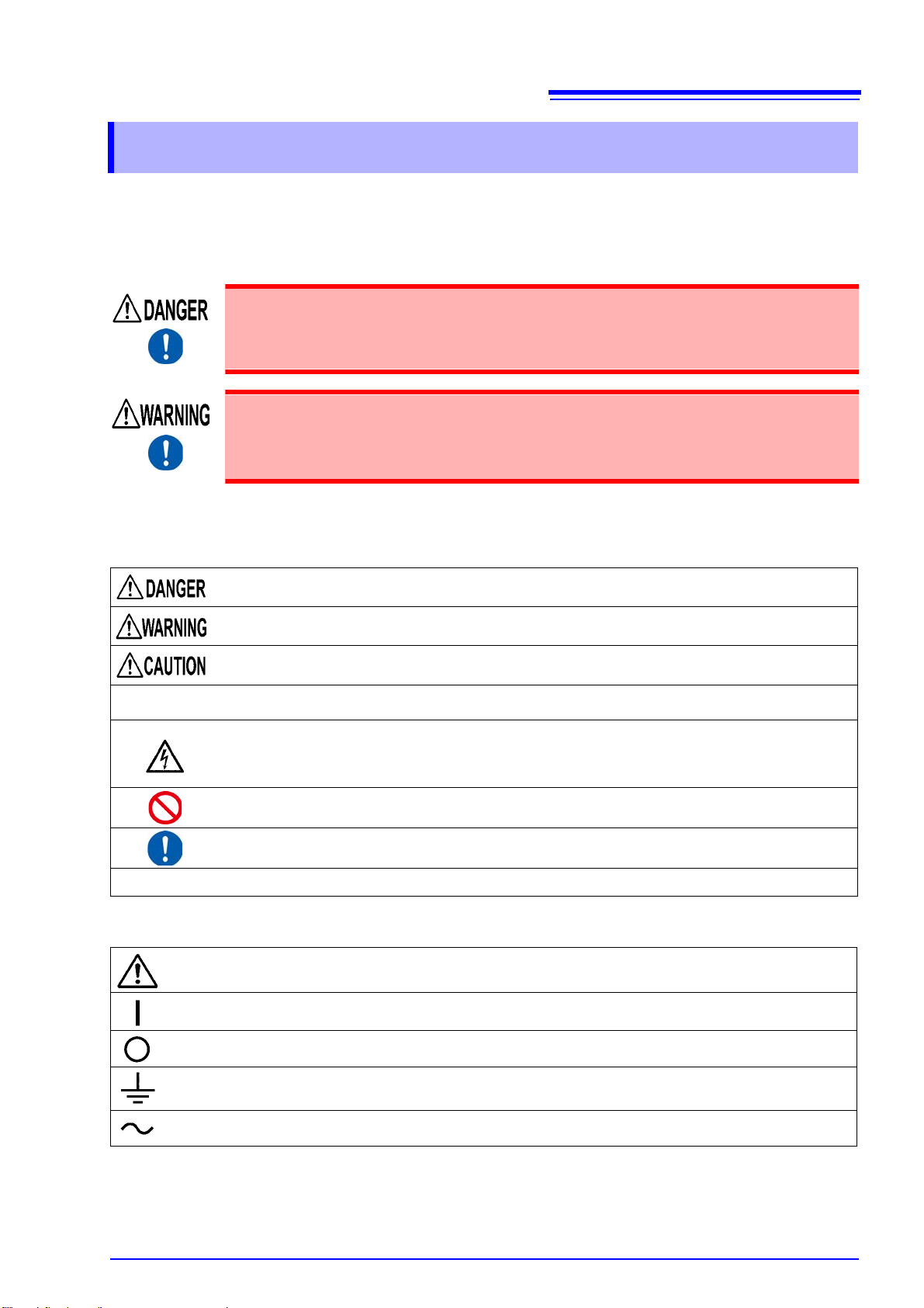
Notation
In this manual, the risk seriousness and the hazard levels are classified as follows.
Indicates an imminently hazardous situation that will result in death or serious injury to the operator.
Indicates a potentially hazardous situation that may result in death or serious injury to the operator.
Indicates a potent ially h azardo us s ituatio n tha t may re sul t in minor or mo derate injury to th e ope rator or
damage to the instrument or malfunction.
IMPORTANT
*
Indicates information related to the operation of the instrument or maintenance tasks with which the
operators must be fully familiar.
Indicates a high voltage hazard.
If a particular safety c heck is not p erforme d or the in strume nt is m ishan dled, th is ma y give rise to a hazardous situation; the operator may receive an electric shock, may get burnt or may even be fatally
injured.
Indicates prohibited actions.
Indicates the action which must be performed.
Additional information is presented below.
Symbols affixed to the instrument
Indicates cautions and h azard s. Whe n the symbol is printed on th e ins trumen t, refe r to a corres pondi ng top ic in
the Instruction Manual.
Indicates the ON side of the power switch.
Indicates the OFF side of the power switch.
Indicates a grounding terminal.
Indicates AC (Alternating Current).
4
Safety Information
Symbols for various standards
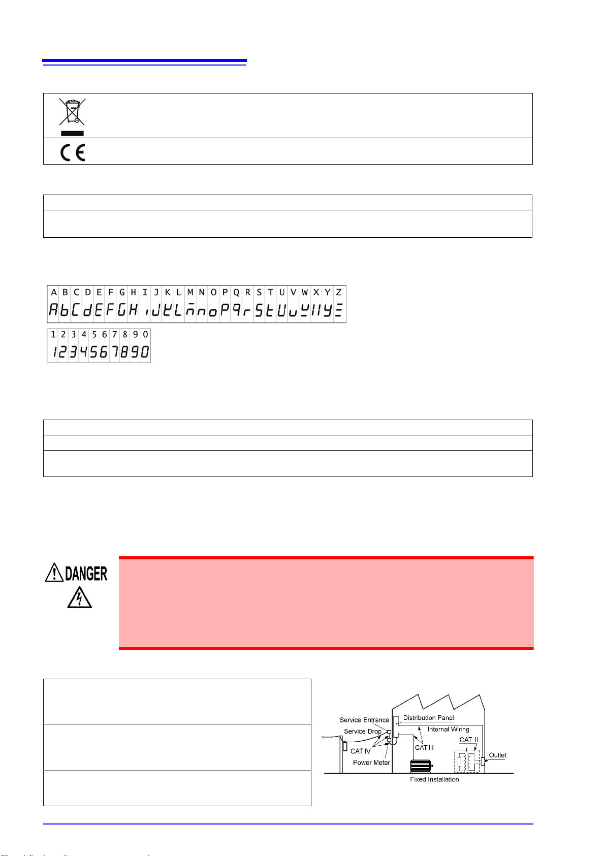
Indicates the Waste Electrical and Electronic Equipment Directive (WEEE Directive) in EU member
states.
This symbol indicates that the product conforms to regulations set out by the EC Directive.
Other Symbols
(p. ) Indicates the location of reference information.
SET
(Boldface)
Screen display
The screen of this instrument displays characters in the following manner.
Bold-faced alphanume ric c haracte rs in the te xt in dicate char act ers show n on the o peratio n key s an d
display panel.
Accuracy
We define measure ment toleran ces in ter ms of f.s. ( full scal e), rdg. ( reading) and dgt. (di git) va lues, wit h the
following meanings:
f.s. (range) This is usually the name of the currently selected range.
rdg. (reading or displayed value) The value currently being measured and indicated on the measuring instrument.
dgt. (resolution)
For example accuracy calculations, see "Appendix 3 Example Accuracy Calculations" (p. A4).
The smallest displayab le unit on a digital me asuring instru ment, i.e., the in put value that causes the digital display to show a "1" as the least-significant digit.
Measurement categories
To ensure safe operation of mea suri ng in stru m ent s, IEC 61010 es tabl is he s sa fety stan dards for va riou s ele ctrical environments, categorized as CAT II to CAT IV, and called measurement categories.
• Using a measuring instrument in an environment designated with a higher-numbered category than tha t for which the instrumen t is rated could result in a severe
accident, and must be carefully avoided.
• Us ing a me asuring instr ument without ca tegories in a n envi ronment de signat ed with
the CA T II to CAT IV category could result in a severe accident, and must be carefully
avoided.
This instrument conforms to the safety requirements for CAT II 1000 V, CAT III 600 V measuring instruments.
CAT II
CAT III
CAT IV
When directly measuring the electrical outlet receptacles of the primary elec trical circui ts in equi pment con nected to an AC electrical outlet by a power cord
(portable tools, household appliances, etc.)
When measuring the primary electrical circuits of
heavy equipment (fixed installations) connected directly to the distribution panel, and feeders from the
distribution panel to outlets
When measuring the circuit from the service drop to
the service entrance, and to the power meter and primary overcurrent protecti on device (di stribution pan el)
Operating Precautions
Operating Precautions
Follow these precautions to ensure safe operation and to obtain the full benefits of the various functions.
Before Use
If the connection cable or the instrument is damaged, there is a risk of electric shock.
Before using the instrument, perform the following inspection.
• Before using the instrument, check that the coating of the connection cables are neither ripped nor torn and that no metal parts are exposed. Using the instrument unde r
such conditions could result in electrocution or a short-circuit. Replace the connection cables with those specified by our company.
• Before using the instrument for the first time, verify that it operates normally to
ensure that no damage occurred during storage or shipping. If you find any damage,
contact your authorized Hioki distributor or reseller.
5
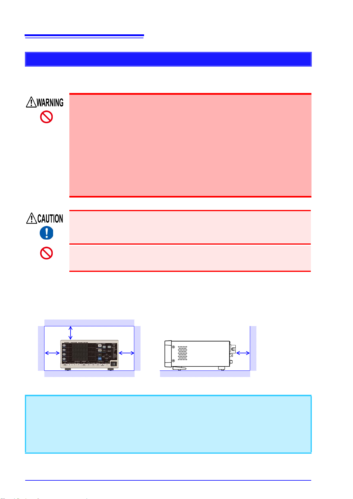
To measure accurately
• Warm up the instrument for more than 30 minutes before use.
• To maintain sufficient measurement accuracy of the instrument, be sure to help heat radiation.
Example: Keeping awa y the instrum ent from a heat, l eaving sufficien t clearance s around the in strument,
installing cooling fans to the rack in which the instrument is mounted, or other measures.
6
50 mm or more
50 mm or more
Operating Precautions
Instrument Installation
For more information abou t the operating temperatu re and humidity range and the s torage temperature an d
humidity range, see "Chapter 5 Specifications" (p.135).
Avoid the following locations that could cause an accident or damage to the instrument.
• Exposed to direct sunlight or high temperature
• Exposed to corrosive or combustible gases
• Exposed to water, oil, chemicals, or solvents
• Exposed to high humidity or condensation
• Exposed to a strong electromagnetic field or electrostatic charge
• Exposed to high quantities of dust particles
• Near induction heating systems (such as high-frequency induction heating systems
and IH cooking equipment)
• Susceptible to vibration
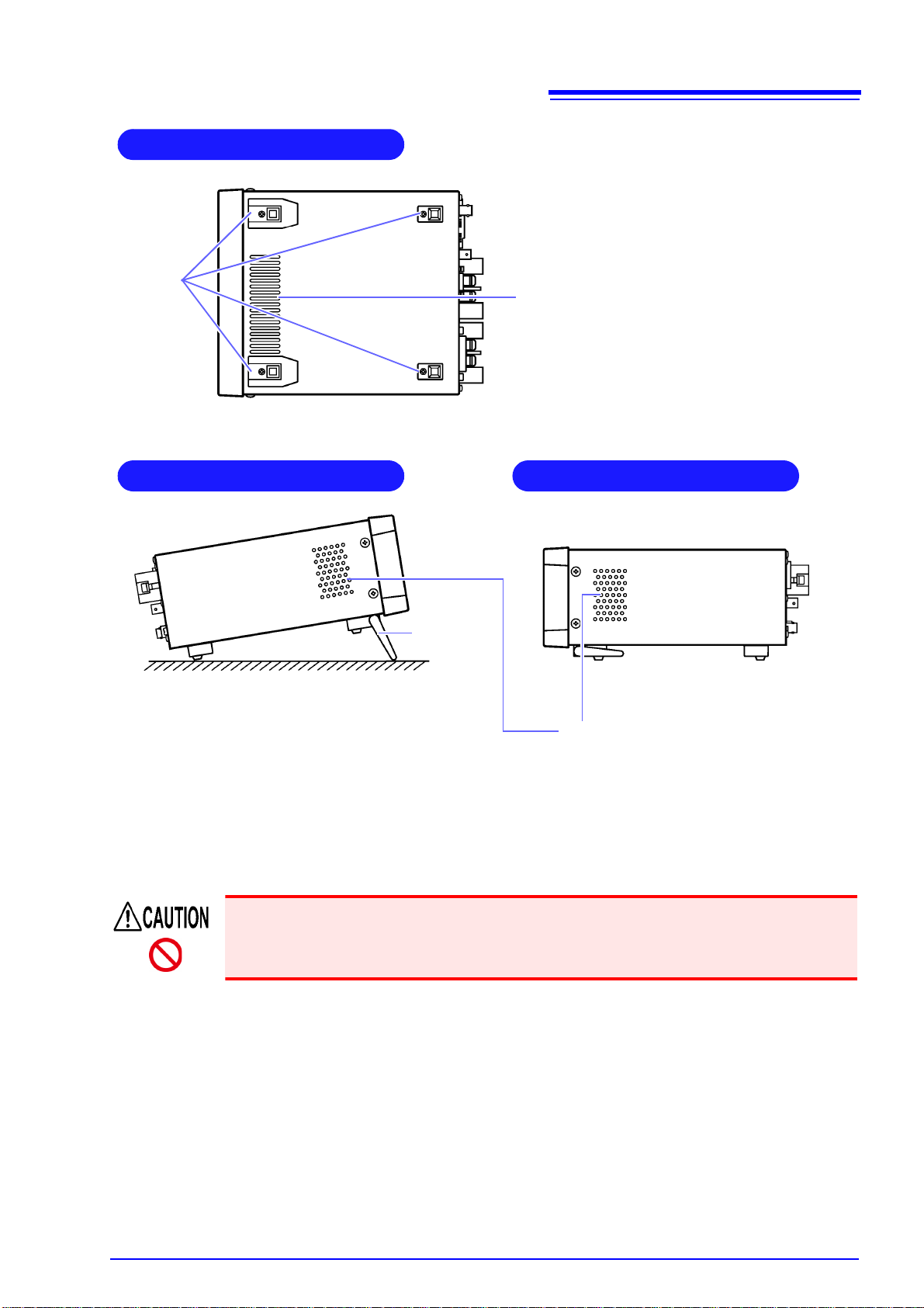
Ventilation holes for heat radiation are provided on the side and rear panels of the
instrument. Leave sufficient space around the ventilation holes and install the instrument with the holes unobstructed. Installation of the instrument with the ventilation
holes obstructed may cause a malfunction or fire.
Do not place another PW3335 or measuring instrument or other heat-generating
device underneath or on top of this instrument. Doing so may damage the instrument
or cause burns or fire.
Installing
To prevent overheating, be sure to leave the specified clearances around the unit.
• The instrument should be operated only with the bottom downwards.
• Vents must not be obstructed.
• Correct measur ement may be impossible in th e presence of strong magn etic fields, such as near transformers and high-curr ent conductors, or in the presence of strong electroma gnetic fields such as near
radio transmitters.
• Unplugging the power cord kills power to the instrument. Be sure to provide enough unobstructed space to
unplug the power cord immediately in an emergency.
• The instrument can be used with the stands flipped out.(p.19)
• To mount the instrument in a rack, refer to "Appendix 4 Rack Mounting" (p. A5)
Handling the Instrument
To avoid electric shock, do not remove the instrument's case.
The internal components of the instrument carry high voltages and may become very
hot during operation.
Do not allow the instrument to get wet, and do not t a ke measurements with wet hands.
This may cause an electric shock.
• To avoid damage to the instrument, protect it f rom physical shock when tr ansporting and
handling. Be especially careful to avoid physical shock from dropping.
• After use, always turn OFF the power.
7
Operating Precautions
This instrument m ay cause interferenc e if used in residenti al areas. Such use mus t be avoided unless the
user takes special measures to reduce electromagnetic emissions to prevent interference to the reception of
radio and television broadcasts.
Handling the Cables
If the insulation on a cable melts, the metal conductor may be exposed. Do not use any
cable whose metal conductor is exposed. Doing so could result in electric shock,
burns, or other hazard.
• Do not move wires connected to the voltage input terminals or current input terminals unnecessarily. Doing so may loosen the connection between the wires and terminals, causing the terminals to heat or melt due to increased contact resistance
and posing the risk of an electrical accident or electric shock.
• Do not tie the cables connected to the input terminals in a bundle with the power
supply cord, the communication cables, the external I/O wires, or the current sensor
cables. Doing so may result in a short-circuit, electric shock, or instrument malfunction.
• Avoid stepping on or pinching cables, which could damage the cable insulation.
• To avoid breaking the cables, do not bend or pull them.
• To avoid damagin g the power cord, gr asp the plug , not the cord, when unplugging it from
the power outlet.
8
Operating Precautions
Connecting, Input and Measurement
• The maximum input voltage is 1000 V DC/AC and the maximum input current to the
current input terminals is 30 A DC/AC.
Attempting to measure a voltage or current in e xcess of eac h of the maximum inputs
could destroy the instrument and result in personal injury or death.
• The maximum rated voltage between input terminals and the ground is as follows;
(CAT II) 1000 V DC, 1000 V AC
(CAT III) 600 V DC, 600 V AC
Attempting to measure voltages exceeding this level with respect to ground could
damage the instrument and result in personal injury.
• The external current sensor input terminals are not insulated. The terminals are
exclusive to the optional current sensors. To prevent instrument damage and bodily
injury, do not connect any device other than an optional current sensor.
• To avoid the danger of electric shock, do not input a signal in excess of the ratings
to the external I/O terminals.
• This instrument should only be connected to the secondary side of a breaker, so the
breaker can prevent an accident if a short circuit occurs. Connections should never
be made to the primary side of a breaker, because unrestricted cu rrent flow could
cause a serious accident if a short circuit occurs.
• To avoid electrica l accidents, confirm that all terminals are secure
resistance of loose connections can lead to overheating and fire.
(Tightening torque of the input terminals: 3 Nm)
Safety covers
• The safety covers play a protective role by preventing contact with the terminals.
Always attach the safety covers before using the instrument.
• Turn off the supply of power to measurement lines before attaching or removing the
safety covers.
. The increased
9
Operating Precautions
When connecting
Observe the following to avoid electric shock and short circuits.
• Turn off the power to lines to be measured before making connections to input terminals and turning on the instrument.
• When making connections, do not mix up the voltage input terminals (U) and the
current input terminals (I). In particular, do not input a voltage across the current
input terminals (between I and ±). Using the instrument with a faulty wiring will dam-
age the instrument or cause injury.
• Be careful to avoid shorting between the voltage input terminals with the wires.
When abnormalities such as smoke, unusual noise, or unusual odor are
observed
Stop the measurement immediately, and observe the following procedure. Us ing the
instrument in such a abnormal condition could cause death or injury.
1. Turn off the power to the instrument.
2. Disconnect the power cord from the outlet.
3. Turn off the power to the line to be measured.
Remove the measurement cables.
4. Contact your authorized Hioki distributor or reseller.
When connecting cables to the input terminals, the communication connectors, or the
external I/O terminals, observe the following to avoid electric shock and short circuits.
• Always turn off the power to the instrument and any dev ice to be connect ed before
making connections.
• Be careful to avoid exceeding the ratings of the input terminal s or external control
terminals.
• During operation, a wire becoming dislocated and contacting another conductive
object can be seriou s ha za rd . Us e t he scr ew s to s ecur e th e commu nicat ion c onne ctors.
For safety reasons, discon nect the power cord when the instrum ent is not used and before
connecting it to a device to be tested.
• To avoid damage to the instrument, do not input the voltage to the output terminals. Also do
not short between any terminals.
• When the instrument is turned off, do not appl y voltage or curr ent to th e inst rument. Do ing
so may cause the instr ument to become hot, resulting in bu rns or damage to the instrument. (p.36)
• Do not connect or disconnect the current sensor or discon nect or connect the c onnection
cord from the 9555-10 Sensor Unit while power is being supplied to the instrument or 9555-
10. Doing so may damage the instrument, current sensor, or 9555-10.
• Do not input current to the current sensor when it is not connected to the instru ment or
when the instrumen t and 9555-10 Sensor Unit ar e turned off. Doing so may dam age the
current sensor, instrument, or 9555-10 Sensor Unit.
The instrument and input terminals may become hot when a large voltage or current is input.

10
Operating Precautions
Before Turning Power On
• Before turning the instrument on, make sure the supply voltage matches that indicated on its power connector. Connection to an improper supply voltage may damage the instrument and present an electrical hazard.
• To avoid e lectri cal acc idents and to maintain the s afety s pecific ation s of this in stru ment, connect the power cord provided only to a 3-contact (two- conductor + ground)
outlet.
See:Connection Methods: "2.3 Connecting the Power Cord" (p.33)
See:
Avoid using an uninterrup tible pow er suppl y (UPS ) or DC/AC i nverter wi th rectangular wave
or pseudo-sine-wave output to power the instrument. Doing so may damage the instrument.

11
Guaranteed accuracy up to 30 A with direct input
High-accuracy, wide-band performance
Standard harmonic measurement function compliant with
IEC 61000-4-7:2002 (p.71)
Extensive measurement functionality, standard
1.1 Product Overview
Overview Chapter 1
1.1 Product Overview
The PW3335 is a power meter that can be used to perform power measu rements for single-phase devi ces
such as battery-driven devices and household electronics.
Thanks to its broad selection of current ranges from 1 mA to 20 A (with an effective measurement range of
10 A to 30 A), it comprise s a single-device solution for measuring pa rameters ranging from stan dby power
consumption to power consumption during normal operation of devices such as household electronics.
1.2 Features
• Accuracy is guaranteed for currents of up to 30 A with direct input.
• (The maximum input current is 30 A, ±100 A peak.)
• An optional current sensor can be used to measure currents in excess of 30 A. (p.100)
• The instrument delivers a high fundamental accuracy of ±0.15% rdg. (at less than 50% of range, ±0.1% rdg.
±0.05% f.s.).
• Over a wide band from DC and 0 .1 Hz to 100 kHz, the instrument covers not only the fundamental frequency band for inverter-driven equipment, but also the carrier frequency band.
• Power factor effects are low at ±0.1%f.s. or less (with a int ernal circuit vo ltage/current phas e difference of
±0.0573°), allowing high-accuracy measurement of active power during low power-factor operation, for
example during no-load testing of transformers and motors.
• The instrument can perf orm harmonic measurement c ompliant with the IEC 61000-4-7: 2002 international
standard on harmonic measurement methods.
• You can set an upper limit for the analyzed order from the 2nd to 50th order according to the harmonic
measurement standard in use.
• Since processing for fun ct ion s s uch as A C+DC (RMS), AC+DC Umn (vol tage aver age va lue re ctif ied RM S
equivalent), DC (DC component), AC (AC component), FND (fundamental wave component), and harmonic measurement a s well as integration m easurement can be per formed internally and in parallel, it is
possible to obtain simultaneous measured values simply by switching the display.

12
High-speed D/A output to capture harsh load variations (p.85)
PW3335-02 PW3335-04
Building a system with 3 interfaces (p.115)
PW3335-01 PW3335-04
Synchronized control function with support for measurement of multiple circuits (p.78 )
1.2 Features
• The PW3335 ca n generate level ( analog) output for each cycle of an input voltage o r input current. Additionally, The active power level can be output for each cy cle for the volta ge or curr ent as signed to th e synchronization source.
• Variations over extended periods of time can be recorded by using the instrument in conjunction with equipment such as a reco rder or data logger usin g leve l outpu t (upda ted eve ry 200 ms ) to me asure param eters
such as voltage, current, and active power.
• Safe, insulated waveforms can be observed using waveform output (equivalent to a sampling rate of
approximately 700 kHz) instantaneous voltage, instantaneous current, and instantaneous power.
• You can control the instrument or capture data from it using a computer by using the LAN interface (standard) or RS-232C interface (excluding PW3335-01). (Y ou can also communicate with a computer over USB
by using a commercially available USB serial [RS232-C] conversion cable.)
• The instrument is also available with a GP-IB interface, which is essential for system development.
( )
• Simultaneous measurement can be performed by connecting two instruments with an optional BNC cable.
• Calculations, di splay updates, data update s, integration contro l, display hold timing , zero-adjustment, and
key lock operation of the instrument set as the slave (IN settin g) are matched to the master instrument
(OUT setting).
• Up to eight inst ruments can pe rform simultaneous measurement, including the PW3336 and the PW3337
series of power meters.
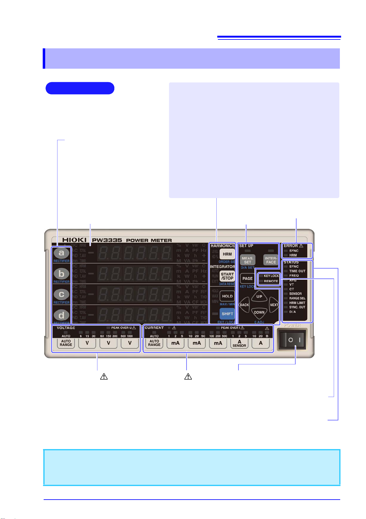
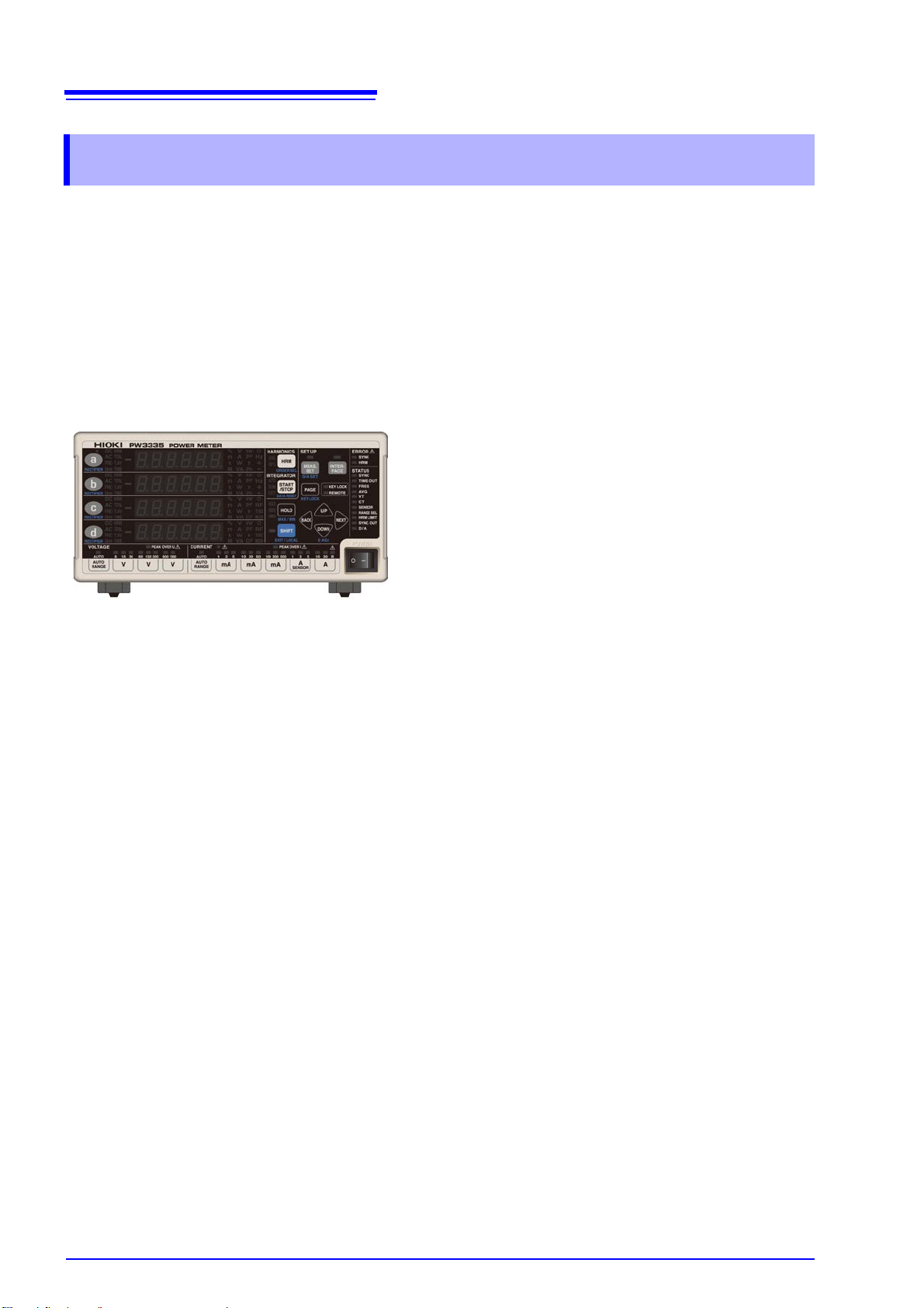
1.3 Names and Functions of Parts
POWER switch (p.34)
Turns the instrument on and off.
Warning lamps (p.17)
CURRENT
●
PEAK OVER I
AUTO and B lamps (p.16)
AUTO
B
Current range (p.43)
Function setting status lamps (p.16)
Light up to indicate activated functions.
Warning lamp (p.17)
PEAK OVER U
AUTO lamp (p.16)
AUTO
Voltage range (p.43)
Front Panel
Example:
PW3335-04
Parameter keys (p.14)
Switch display parameters.
RECTIFIER (p.42)
Switches the rectifier in the shift state.
Display
Switches between measured
values and setting values.
Error lamps
(p.17)
Function setting
keys (p.17)
Configure functions.
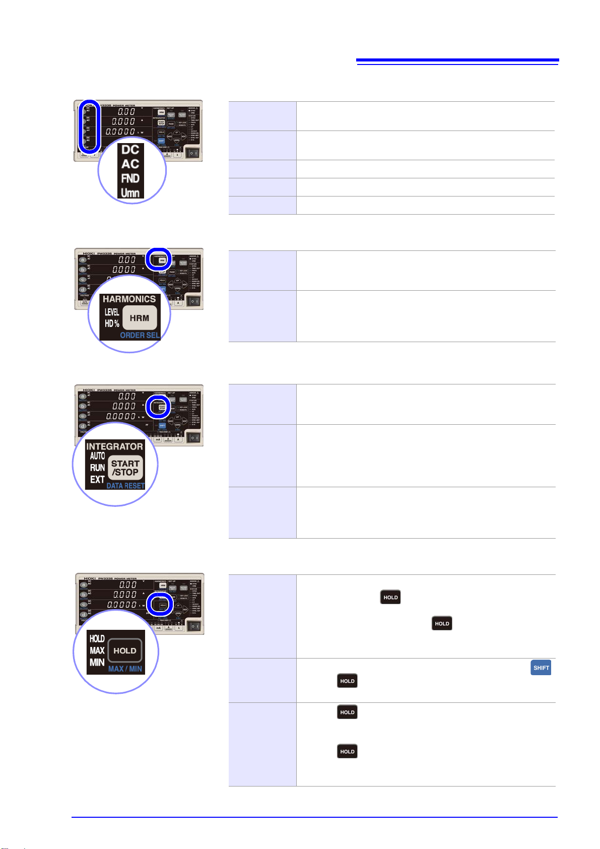
HRM (ORDER SEL)
Harmonic display (switch among level, content percentage, and
normal display) (Choose the orde r you wish to display in the shift
state.)
HOLD (MAX/ MIN)
Holds display values (switches between maximum and minimum
values in the shift state).
SHIFT (EXIT/ LOCAL)
Activates the SHIFT state (the lam p will light up while in the SHIFT
state). (p.14)
(Switches from settings mode to the normal measurement state
and from the remote state to the local state.)
START/STOP (DATA RESET)
Starts/stops integration (resets integrated values in the shift state).
Function setting status lamps (p.16)
Light up to indica te w h en set tings differ from
default settings.
1.3 Names and Functions of Parts
13
• The shift state is automati c all y c anc el ed after App ro x. 10 se co nds. W hen th e RECTIFIER key is pressed,
the shift state is canceled after Approx. 2 seconds.
• If key operation causes a message or indication that is not described in this manual to be displayed,
immediately cycle the instrument’s power.
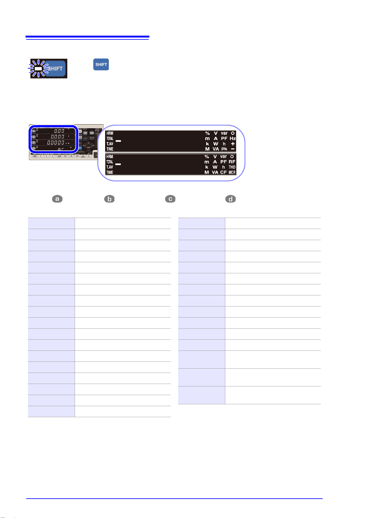
14
Press to light up the blue lamp be fore setting functions shown in blue underneath t
keys.
Pressing on the first row, on the s ec ond ro w, on the th ird row, or on the fourth row of the m eas ure d
value display switches the display parameter, causing the selected display parameter to light up.
V Voltage (U)
A Current (I)
W Active power (P)
VA Apparent power (S)
var Reactive power (Q)
PF Power factor ()
° Phase angle (φ)
V Hz Voltage frequency (f)
A Hz Current frequency (f)
Ah + Positive current integration
Ah - Negative current integration
Ah Current integration sum
Wh + Positive active power integration
Wh - Negative active power integration
Wh Active power integration sum
TIME Integration time
V pk Voltage waveform peak value (Upk)
A pk Current waveform peak value (Ipk)
CF V Voltage crest factor (Ucf)
CF A Current crest factor (Icf)
MCR Maximum current ratio
T.AV A Time average current (T.AV I)
T.AV W Time average active power (T.AV P)
RF V % Voltage ripple rate (Urf)
RF A % Current ripp le rate (Irf)
THD V % Total harmonic voltage distortion (Uthd)
THD A % Total harmonic current distortion (Ithd)
HRM V LEVEL Harmonic voltage RMS value (Uk)
HRM A LEVEL Harmonic current RMS value (Ik)
HRM W LEVEL Harmonic active power (Pk)
HRM V % HD%
Harmonic voltage content percentage
(UHDk)
HRM A % HD%
Harmonic current content percentage
(IHDk)
HRM W % HD%
Harmonic active power content percentage (PHDk)
1.3 Names and Functions of Parts
Activates the SHIFT state
Display parameters
1.3 Names and Functions of Parts
DC AC
When using the AC+DC r ectifier, both the D C and AC lamps light
up.
DC AC Umn
When using the AC+DC Umn rectifier, the DC, AC, and Umn
lamps light up.
DC Lights up when using the DC rectifier.
AC Lights up when using the AC rectifier.
FND Lights up when using the FND rectifier.
LEVEL
Lights up when the instrument is displaying a harmonic component level (harmoni c voltag e RMS val ue, harmo nic curre nt RMS
value, or harmonic active power).
HD%
Lights up when the instrument is displaying a harmonic content
percentage (harmonic voltage content percentage, harmonic
current content percentage, or harmonic active power content
percentage).
AUTO
Indicates the integratio n opera ting mode.
AUTO lamp on: Auto-range integration mode
AUTO lamp off: Fixed-range integration mode
RUN
Indicates the status of integration based on START/STOP key
operation or communications.
RUN lamp on: Integration active
RUN lamp flashing: Integration stopped
RUN lamp off: Integration reset
RUN
EXT
Indicates the status of integration based on external control.
RUN lamp on, EXT lamp on: Integration active
RUN lamp flashing, EXT lamp on: Inte gration stopped
RUN lamp off, EXT lamp off: Integration reset
HOLD
When the HOLD, MAX, and MIN lamps are all off, pressing the
SHIFT key and then causes the instrument to enter the d isplay hold state and the HOLD lamp to light up.
To cancel display hold: Pressing once more causes the
display hold state to be canceled and the HOLD lamp to be
turned off.
MAX
When the HOLD, MAX, and MIN lamps are all off, pre ssing
and then causes the maximum value to be held and the
MAX lamp to light up.
MIN
Pressing while the MAX lamp is lit up (indicating that the
maximum value is being held) causes the minimum value to be
held and the MIN lamp to light up.
Pressing while the MIN lamp is lit up (indicating that the
minimum value is be ing held) cause s the minimum v alue hold to
be canceled, returning to the normal measured value display.
Rectifier indic a tor lamps (p.42)
Harmonic measurement (HARMONICS) lamps (p.71)
15
Integration (INTEGRATOR) status indicator lamps (p.61)
Hold (HOLD) status indicator lamp (p.106)
16
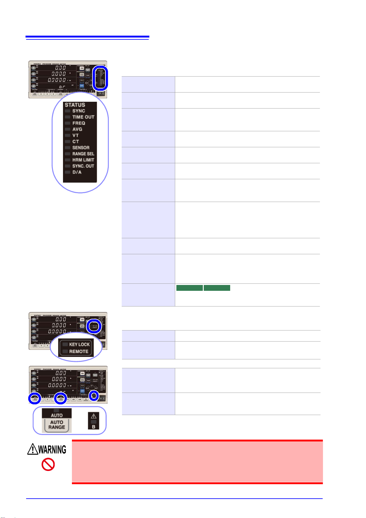
These lamps indicate the setting status.
Function lamps light up when set to a value other than the default setting.
SYNC
Lights up whe n the s ynchroni zation s ource is se t to I o r DC
(the default setting is voltage: U). (p.48)
TIME OUT
Lights up when t he synchronizati on detection tim eout is set
to 1 sec. or 10 sec. (the default setting is 0.1 sec.). (p.54)
FREQ
Lights up when the zero-cross and frequency measurement filter setting is set to 100 Hz, 5 kHz, or 100 kHz (the
default setting is 500 Hz). (p.50)
AVG
Lights up when the numb er of averagin g iterati ons is set t o
a value other than the default value of 1. (p.56)
VT
Lights up when the VT ratio setting is set to a value other
than the default setting of 1. (p.58)
CT
Lights up when the CT ratio setting is set to a value other
than the default setting of 1. (p.58)
SENSOR
Lights up when the current input method setting is set to
TYPE.1 or TYPE.2 (current sensor input) (the default setting is OFF [current value direct input]). (p.38)
RANGE SEL
Lights up when either the voltage measurement range or
current measurement range is set to OFF. (the default setting is range select: ON). (p.46)
Lights up when any of the zero -cross threshold l evels is set
to a value other than the default setting of 1%. (p.52)
HRM LIMIT
Lights up when the harmonic analysis order upper limit is
set to a value other than the default value of 50. (p.76)
SYNC. OUT
Lights up when the sync hronized m easurement I/O setting
is set to OUT (Master). Fla shes with extern al synchronize d
signal input when set to IN (Slave). Turns off when set to
OFF. (p.78)
D/A Light s u p w h en t he 7 channels of D/A o utp ut a re s et to v al -
ues other than their default values. (p.88)
PW3335-02 PW3335-04
These lamps indicate the instrument’s overall setting status.
They light up when the corresponding function is ON.
KEY LOCK Lights up when key operation is disabled. (p.109)
REMOTE
Lights up when the instrument is in remote opera tion mode.
(p.133)
AUTO
Lights up when the volta ge or curre nt m eas ure me nt ran ge
is set to auto range (the d efault se tting is auto rang e OFF) .
(p.43)
B
Indicates the B 20 A range used in auto-range integration
mode. Lights up when a ran ge is sele cted while i ntegrati on
is stopped. (p.61)
1.3 Names and Functions of Parts
Function setting status lamps
When the VT and CT lamps are lit up (particularly when the VT ratio and CT ratio are
set to values less than 1), a voltage or current g reater than the displayed measured
value may have been input to the instrument. To prevent an electrical accident or
short-circuit, do not unn ecessarily touch the instrument’s input term inal or the measurement lines.
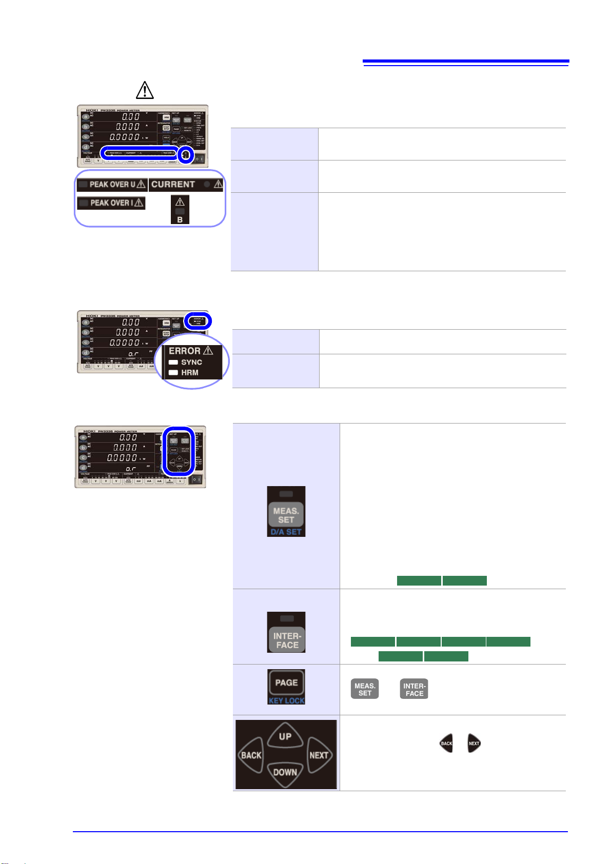
Warning indicator lamps
The following warning lamps are lit up when there is a hazard or the instrument is
unable to perform measurement accurately:
PEAK OVER U
Lights up when an overvoltage inp ut warning o ccurs, indica ting that the input vo ltage peak valu e has exceeded ± 1,500 V
or ±600% of the voltage measurement range.
PEAK OVER I
Lights up when an o vercurren t input wa rning occurs , indica ting that the input current peak value has exceeded ±100 A
or ±600% of the current measurement range.
CURRENT ●
Instrument protectio n mode. Flas h when if current of greater
than or equal to ±612 mA peak is inputted continuously for
10 or more seconds when using a range from 1 mA to 100
mA with fixed range.
If you attempt to switch from one of the 200 mA to 20 A ranges to one of the 1 mA to 100 mA ranges while a current of
±612 mA peak or great er is being inp ut, you will not be able
to switch ranges, and the indicator will flash.
The following error lamps are lit up when the instrum ent is unab le to perform measurement accurately:
SYNC
Lights up when a synchronization error occurs, indicating
that synchronization cannot be detected. (p.48)
HRM
Lights up when a harmonic measurement synchronization
error occurs, indicating that the harm onic measurem ent synchronization frequency range was exceeded. (p.71)
MEAS. SET
The lamp will light up if presse d when the foll owing settings are being configured:
• Synchronization source
• Current input method
• Range select
•CT ratio
•VT ratio
• Frequency measurement range (zero-cross filter)
• Synchronization detection timeout
• Integration time, auto-range integration
• Number of averaging iterations
• Harmonic analysis upper limit order
• Synchronized measurem ent I/O (master, slave)
• D/A output
INTERFACE
The lamp will light up if pressed when setting the interface.
•LAN
• RS-232C
•GP-IB
• Used to switch among settings configured with
and .
• Used with the key lock function.
Used to move among and select settings.
• Pressing and holdin g or will caus e the flash-
ing setting to move successively.
PW3335-02 PW3335-04
PW3335 PW3335-02 PW3335-03 PW3335-04
PW3335-01 PW3335-04
Error indicator lamps
17
1.3 Names and Functions of Parts
Function setting keys and indicator lamps
18
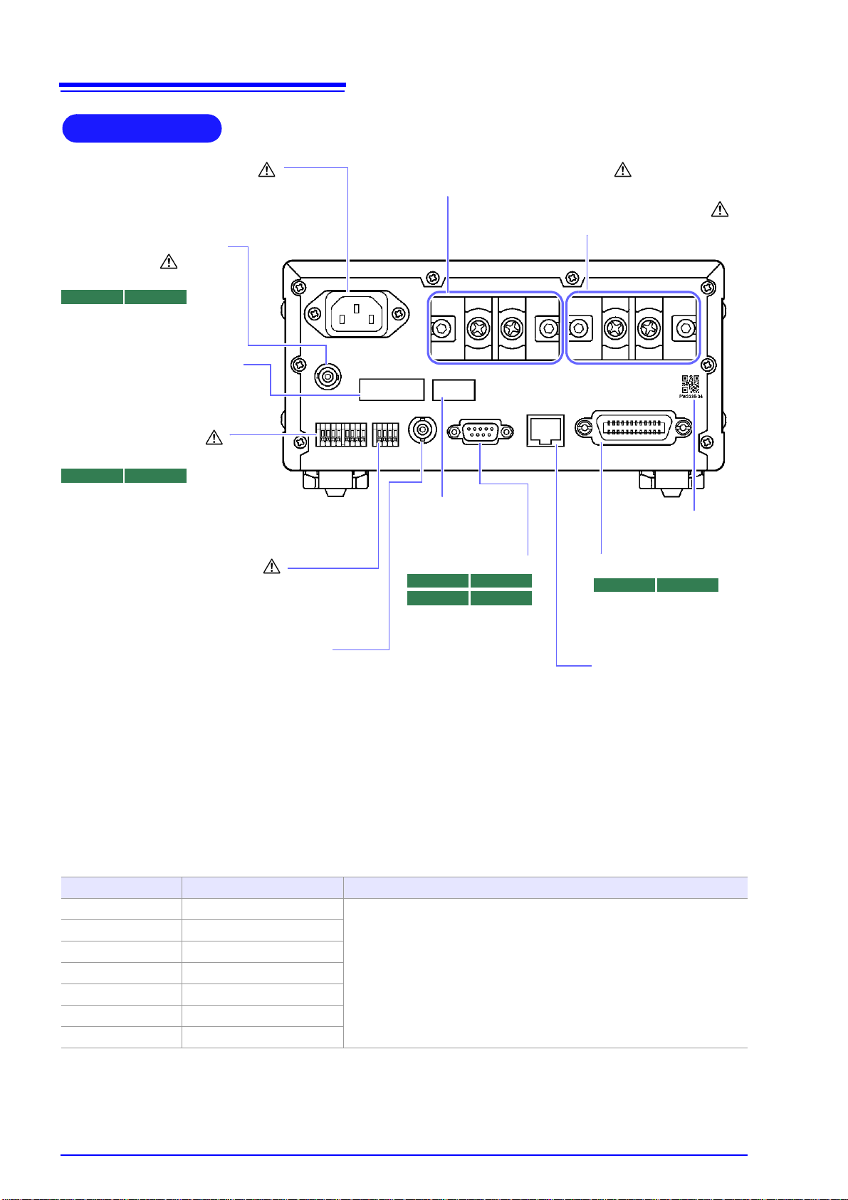
Power Inlet
Connect the supplied
power cord. (p.33)
Model name number
Current input terminal ( I )
Input current signals. (p.26)
Voltage input terminal (U )
Input voltage signals. (p.26)
Example: PW3335-04
External control terminal
(EXT. CONTROL)
Input signals from an integration
external control function. (p.82)
D/A Output terminal
*
(D/A OUTPUT)
The voltages listed below
are output from each
terminal. (p.85)
PW3335-02 PW3335-04
External current sensor
input terminal
(CURRENT SENSOR)
Connect the optional current
sensors. (p.100)
PW3335-03 PW3335-04
Manufacturer's Serial No.
Do not remove this labe l, as it is
required for product support.
MAC address
of the LAN
RS-232C connector
Connect a communications cable when using
the RS-232C interface.
(p.123)
PW3335 PW3335-02
PW3335-03 PW3335-04
GP-IB connector
Connect a communications cable when u sing the
GP-IB interface. (p.127)
PW3335-01 PW3335-04
LAN connector
Connect a communications cable when u sing the
LAN interface. (p.116)
External synchronization terminal
(EXT. SYNC)
Connect a cable for synchronized
measurement. (p.78)
Rear
1.3 Names and Functions of Parts
*D/A OUTPUT terminals
The following voltages are output from each terminal.
Level output: Level (analog) output is updated at an interval of approximately 200 ms.
High-speed level output: The active power for every cycle for the voltage or current set as the synchronization source is
Waveform output: The input waveform as sampled at a frequency of approximately 700 kHz is output.
Terminal Default setting Description
DA1 V : AC+DC, STD.2 Each D/A output terminal can be set to any of the following:
DA2 A : AC+DC, STD.2
DA3 W : AC+DC, STD.2
DA4 PF : AC+DC, STD.2
DA5 V : AC+DC, FASt
DA6 A : AC+DC, FASt
DA7 W : AC+DC, FASt
output.
• Level output
• High-speed level output
• Waveform output
Appendix 2 Detailed Specifications of Output (p. A2)
See:
19
Bottom panel
This instrument can be rack-mounded by
removing its feet.
See: Appendix 4 Rack Mounting (p. A5)
Parts removed from this instrument should
be stored in a safe place to enable future
reuse.
Feet
Vents
Keep clear of obstruction s.
Left side
When using the stands
Open the stands un til th ey cli cks i nto pl ace. Be
sure to use both stands.
When folding up the stands
Fold up the stands until they click into place.
Right side
Vents
Keep clear of obstructions.
Clean the vents periodically to avoid
blockage.
Stand
1.3 Names and Functions of Parts
Do not apply heavy downward pr essure with the stand extended . The stand could be damaged.
20
Installing the Instrument (p.6)
CHECKS
• Are the wires from the measurement targets shut off?
• Is the instrument turned off, and has the power cord been disconnected?
• Using D/A output(p.85)
• Using synchronized control to conduct measurements with multiple instruments simultaneously (p.78)
• Using external control to control integration (p.61)
• Sending and receiving data with the RS-232C, LAN, and GP-IB
interfaces (p.115)
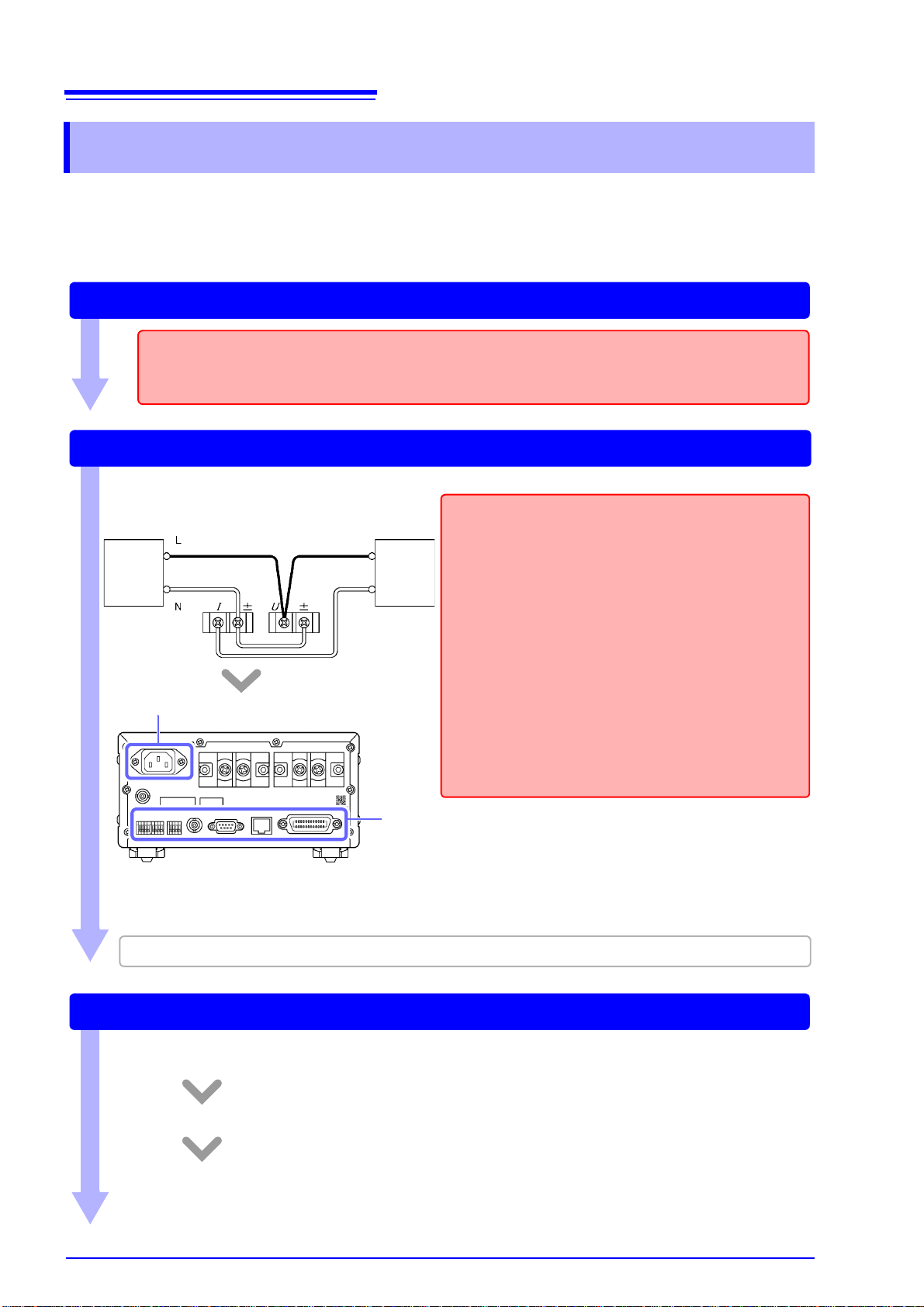
Connecting Wires and the Power Cord
Connect the measurement lines to the instrument and then connect the power cord to the instrument.
CHECKS
• Is the instrument connected on the secondary side of
the circuit breaker?
• Does the circuit being used exceed 1,000 V?
• Does the voltage or current being measured exceed
1,000 V or 30 A, respectively?
If so, use VT and CT.
• Are appropriate ty pe s o f wi re be i ng us ed to co nne ct to
the voltage and current input terminals?
Use solderless terminals that cover wiring with insulation. Moreover, use wire with adequate dielectric
strength and current capac ity.
• Has the wiring been shorted?
• Are the input terminals loose?
• Have wires been co nne cte d pr ope rly ?
Connect wires. (p.26)
Example:
Connect the power cord. (p.33)
When using one or more current sensors, see "3.8 Using a Current Sensor" (p.100).
Source Load
Turning on the instrument (p.34)
Before turning on t he ins tr um ent, ver ify th at the wires have b een conn ec ted pr ope rly on e m ore time.
After displaying the initial screen, the instrument will display input values under the current settings.
Allow the instrument to warm up for at least 30 minutes.
Perform zero-adjustment.
To fulfill the instrumen t’s accur acy spe cific ation s, be sure to pe rfor m zero-a djustm ent for th e voltag e
and current measured values.
1.4 Measurement Workflow
1.4 Measurement Workflow
1 Install the instrument, connect wires and cords, and
turn on the instrument.
21
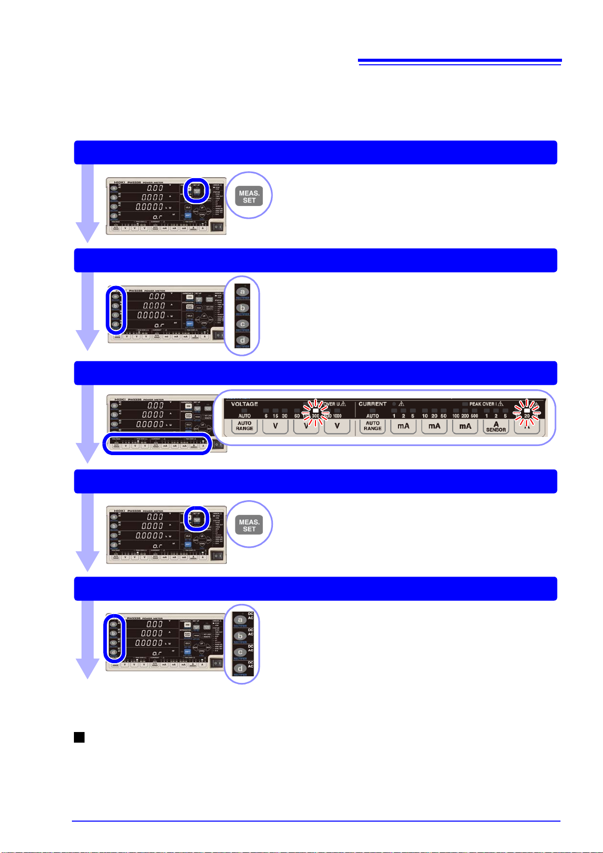
Setting the current input method (p.38)
Selecting display parameters (p.40)
Selecting voltage and current ranges (p.43)
Setting the synchronization source (p.48)
Selecting rectifiers (p.42)
Configure the following settings as necessary:
When SYNC lamp (ERROR) lights up: Setting the frequency measurement range
See: "3.2.5 Setting the Frequency Measurement Range (Zero-cross filter)" (p.50)
1.4 Measurement Workflow
2 Configure settings. (These settings can also be
changed during measurement.)
22
Addressing display value variation: Displaying average measured values
See: "3.2.7 Displaying Measured Values as an Average (AVG: Averaging)" (p.56)
Measuring voltages in excess of 1,000 V: Using VT (PT) to make measurements
See: "3.2.8 Setting the VT Ratio and CT Ratio" (p.58)
Measuring currents in excess of 30 A: Using CT to make measurements
See: "3.2.8 Setting the VT Ratio and CT Ratio" (p.58)
When you wish to perform integration
See: "3.3 Integration" (p.61)
When you wish to measure harmonics
See: "3.4 Viewing Harmonic Measured Values" (p.71)
When you wish to hold the display, or display the peak value, minimum value, or
maximum value
See: "3.9.1 Fixing Display Values (Display Hold)" (p.106)
"3.9.2 Displaying Maximum, and Minimum Values (MAX/MIN)" (p.107)
When you wish to use D/A output
See: "Output voltage of level output"(p.95)
PW3335-02 PW3335-04
When you wish to use the RS-232C interface
See: "Setting the RS-232C communications speed"(p.124)
When you wish to use the LAN interface
See: "Setting the LAN’s IP address"(p.117)
When you wish to use the GP-IB interface
See: "Setting the GP-IB address"(p.129)
PW3335-01 PW3335-04
When you wish to perform synchronized measurement wi t h multiple instruments
See: "3.5 Performing Synchronized Measurement with Multiple Instruments" (p.78)
1.4 Measurement Workflow
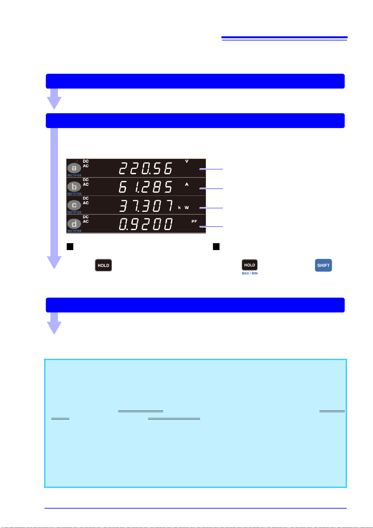
3 Start measurement.
Activating power to the measurement lines
Measuring and outputting data
The instrument will display the measured values.
You can change the voltage and current range as well as display parameters during measurement.
Example:
When you wish to hold display
values (p.106)
Press .
Displaying maximum and minimum
values (p.107)
Press while holding down .
Voltage
Current
Active power
Power factor
Turning off the instrument
Turn off power to the measurement lines and after disconnecting the cords from the measurement target, turn off the instrument.
See: "2.4 Turning On the Instrument" (p.34)
23
1.4 Measurement Workflow
4 Stop measurement.
About measured values
• The instrument’s apparent power (S), reactive power ( Q ), powe r fact or ( ), a nd ph as e an gle ( ) are calculated based on the measur ed vol tage (U), cu rre nt (I), and ac tive power (P). For the actual e quat ion s used ,
see "5.5 Calculatio n F ormulas Specifications" (p.159) . Values displayed by the i ns tr ume nt m ay differ from
values displayed by measuring instruments that use different operating principles or equations.
• Vol tage values that a re less than ±0.5%
±0.5% of the measu rement range or less than ±9 A w ill be forcibly displayed a s zero. (this is known as
zero-suppression).
• Measured values may include an error component in measu re men ts in which a terminal - to-gr ou nd vol tage
with a high frequency is input.
• Display values may exhibit variatio n in applications in which the frequ encies of the voltage and current
being measured differ.
• Measured values may include an error comp onent when the instrument is used nea r a strong magnetic
field such as that gen erated by a transformer or hig h-current path, a strong electric field generated by a
radio or similar device, or a high-frequency magnetic field generated by a high-frequency current.
of the measurement range and curre nt values that are less than

24
1.4 Measurement Workflow
 Loading...