

Page 1

PQ3100
POWER QUALITY
ANALYZER
Measurement Guide
Thank you for purchasing the Hioki
PQ3100 Power Quality Analyzer.
This guide introduces the instrument's
basic measurement procedure to rst-time
users with Quick Set.
Before using the instrument, be sure to
read the Instruction manual carefully.
EN
July 2017 Revised edition 1
Printed in Japan PQ3100A971-01 17-07H
Quick Set for Setting
Try to check for the power supply malfunction
in a 3-phase 4-wire 230 V line.
Setting Items Setting Example
Wiring: 3P4W (3-phase/4-wire)
Declared input voltage: 230 V
Measurement
frequency: 50 Hz
Current sensor: CT7045
Current range: 50 A
Easy settings course: Voltage events
Recording start method: Interval
Recording stop method: Manual
1. Preparations
Install the
1
Battery Pack.
Easy
Colored clips
for current sensors
Wind the clips of the same
2 3 4
color as the channels
around the leads.
(CH1) (CH2)
You will need
Model PQ3100
Model Z1002 AC Adapter
Red (CH1)
Yellow (CH2)
Blue (CH3)
Model Z1003
Battery Pack
Insert the SD
memory card.
(CH3)
Model L1000-05 Voltage Cord
Model CT7045 AC Flexible Current
Sensor (optional)
Model Z4001 SD
Memory Card 2GB
(optional)
Connect the AC
adapter.
(Wiring image)
Z1003
Red
2. Starting Quick Set
Turn on the instrument.
1
(Language, clock and measuring frequency are
required to be set only during the rst setting.
Refer to the Instruction Manual.)
Press the
2
key.
Press the key.
3
Yellow
CT7045
Blue
Right side of the instrument
Refer to Chapter 2 on the Instruction Manual.
3. Basic Settings
Settings for the wiring.
1
3P4W
Left side of the
instrument
1. Move cursor
2. Display dropdown list
3. Select wiring
4. Settle setting
Refer to Chapter 3 on the Instruction Manual.
To exit in the middle of settings
Press any of the other screen switching keys.
All the settings before the exit are saved.
Find Quality Products Online at: sales@GlobalTestSupply.com
www.GlobalTestSupply.com
Press the (Next)
2
key.
Refer to Section 1.6 on
the Instruction Manual.
Page 2

4. Connections with the Instrument
Connect the voltage cords to the voltage
1
Colored clips
input jacks.
Connect the current sensors to the current
2
input jacks.
The current sensors will be automatically identied.
Check that the SD memory card is inserted.
Connect the cords
to each of the same
color jacks.
Refer to Sections 4.3 through 4.5 on the Instruction Manual.
3
Without connecting the voltage cords and
4
current sensors to the measuring lines,
press the [F2] (Next) key.
Zero adjustment will be automatically performed.
5. Wiring Voltage Cords to the Measuring Object
Refer to the wiring diagram to check the locations
1
to which the voltage cords have to be connected.
Attach the voltage cords to the secondary side of
2
the breaker.
Check the vectors and measured values.
3
Check the declared input voltage.
4
In completion of the wiring, values will be set automatically.
If the values are different from the actual values, change the
5
6
Refer to Section 4.6 on the Instruction Manual.
values.
Check the wiring judgment.
If all the items are judged to be
(green):
(You can proceed to the next step
even with
Press the [F2] (Next) key.
If (red) or (yellow) is displayed:
1. Move the cursor to the (red) or
(yellow) items.
(red) or (yellow).)
2. Press the [ENTER] key.
3. Refer to the key points shown in the
dialog to correct the wiring.
Align the
arrow with the
concave portion
of the terminal
to insert the
connector.
Current input jack
A
B
C
N
For a bus bar, pinch the
metal part.
Red
Yellow
Blue
Black
6. Wiring Current Sensors to Measuring Object
Refer to the wiring diagram to check the
1
locations to which the current sensors have to be
connected.
Attach the current sensors around the wires
2
connected to the secondary side of the breaker.
Verify that the measured values are displayed.
3
Set the current range.
4
Press the [F2] (Next) key.
5
Refer to Sections 4.7 and 4.8 on the Instruction Manual.
Current
direction
mark
Attach the sensor around
only one of the conductor.
Source
Load
Tip
Set the current range based on the maximum load current expected to ow during the measurement period.
(Consult the operating status, load rating, breaker rating, and other data to make this determination.)
If the range is too low, the instrument will experience an overrange event during measurement. The error component increases if the
range is too high. Current cannot be measured accurately in any of the above cases.
Find Quality Products Online at: sales@GlobalTestSupply.com
www.GlobalTestSupply.com
Page 3
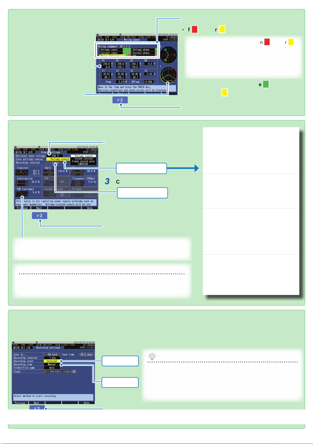
7. Wiring Check
Check the measured values
1
and vectors.
Check the wiring in the following cases.
• Measured values of the channels are
low, or active power Psum shows a
negative value.
• Displacement power factor DPFsum is
below 0.5.
• The vector position is outside the
PASS range.
Refer to Section 4.9 on the Instruction
Manual.
Check the wiring judgment.
2
• If (red) or (yellow) is displayed:
1. Move the cursor to the item in (red) or
(yellow) item.
2. Press the [ENTER] key.
3. Refer to the key points shown in the dialog to
correct the wiring.
•
If all the items are judged to be (green):
•
The color was (yellow) but the wiring check
did not indicate any problems:
Press the [F2] (Next) key.
3
8. Event Settings
Check the declared input
1
voltage.
Select the easy settings course.
2
Voltage events
Check the recording interval.
3
1 min
Changes can made in
“Step 9. Recording Settings”.
Press the [F2] (Next) key.
4
Events that can be measured with the selected menu are displayed.
(Events are displayed with light color cannot be measured.)
Easy settings course
Threshold values for events and recording interval will be automatically congured.
To make any change to the event settings, press the [SETUP] key after
completion of Quick Set to display the Event Settings screen.
Voltage events
This is used to investigate the cause
of power supply abnormalities such as
equipment malfunction.
Voltage components (swell, dip, interruption)
and frequency are monitored.
The recording interval will be set to 1 minute.
Inrush current
This is used to measure the inrush current.
Event thresholds for inrush current is set
to 200% of current RMS and the recording
interval to 1 minute.
Trend record only
This is used to record measured values over
an extended period of time.
All the event settings (effective only for
manual events, recording start events, and
recording stop events) are set to OFF and
recording interval is set to 10 minutes.
EN50160
This is used to measure in conformance to
the European Norm EN50160.
The recording interval is set to 10 minutes.
(The recording interval is xed to 10
minutes. Cannot be changed.)
Refer to Section 5.3 on the Instruction Manual.
9. Recording Settings
Congure the Recording start and Recording stop.
1
Interval: Recording will start at a well-dened time in accordance with the Recording
interval.
Interval
Manual
Press the [F2] (Next) key.
2
Find Quality Products Online at: sales@GlobalTestSupply.com
www.GlobalTestSupply.com
Tip
If the Save time is less than the measurement period, the following
methods can be used to increase the save time:
• Recording interval: Lengthened
• SD memory card: Delete unnecessary data, and format it.
(Exit the Quick Set and use the FILE screen.)
Refer to Section 5.2 on the Instruction Manual.
Page 4

10. Checking Settings and Recording
Check the settings.
1
To make any changes to the settings, press the [F1] (Previous) key to return to
applicable screen.
START/STOP LED
Refer to Chapter 7 on the Instruction Manual.
*: Interval
Recording start
Press the key.
2
The instrument enters the standby state.
(START/STOP LED: Blinking)
The recording will start at the time set by the
interval*.
The instrument enters the recording state. (START/
STOP LED: On)
To start recording after setting the items
that are not listed in Quick Set.
Press the [F5] (End) key.
The settings congured up to this point will be
saved.
Recording stop
Press the key.
3
The recording stop dialog will be displayed.
Press the key.
4
In case of Recording interval:
5 min
Recording
11
10
9
8
7
Example 1:
Example 2:
12
6
Recorded
12:43 12:45
start
1
Recorded
2
Recorded
3
4
Recorded
5
Recorded
4:02 4:05
Fluctuations in measured
values during recording can be
monitored.
Press the [TREND] key to display the
TREND screen.
The measured items in the form of a
time series graph can be observed.
Refer to “8. Verifying the Trends
(Fluctuations) in Measured Values”
on the Instruction Manual for details.
Recording will be stopped. (START/STOP LED: Off)
Event occurrence status during
recording can be monitored.
Press the [EVENT] key to display the
EVENT screen.
Event occurrence status can be
checked.
Refer to “9. Checking Events” on the
Instruction Manual for details.
Recorded data can be postanalyzed with a computer.
Data after completion of recording
can be analyzed with a computer
using the supplied PC application
software.
Functions:
• Observing time series data, event
data, and event waveform
• Observing statistics data
• Creating reports
Refer to “11. Analysis (with Computer)”
Find Quality Products Online at: sales@GlobalTestSupply.com
www.GlobalTestSupply.com
on the Instruction Manual for details.
 Loading...