


PR8111
PR8112
PEN RECORDER
Instruction Manual
Feb. 2020 Revised edition 3
PR8111A981-03 20-02H
EN


Contents
Basic Operation.............................................. 1
Introduction.....................................................2
Confirming Package Contents........................2
Safety Information ..........................................3
Operating Precautions....................................5
i
Contents
Chapter 3
Configuring the Instrument
and Taking Measurements 23
3.1 Configuration and Measurement
Process ..............................................23
Chapter 1
Overview 9
1.1 Product Overview and Features ..........9
1.2 Names and Functions of Parts ........... 10
SPAN (span adjustment) .......................... 12
Chart cover ............................................... 12
Chapter 2
Measurement Preparations 13
2.1 Pre-Operation Inspection ................... 13
2.2 Loading Recording Paper .................. 14
Loading Fanfold Recording Paper ............ 14
Loading Roll Recording Paper.................. 15
2.3 Installing the Pens .............................. 16
Installing Pens and Using the Pen Caps .. 16
2.4 Connecting the Power Source
(Alkaline Batteries or AC Adapter) ..... 17
Installing Alkaline Batteries....................... 17
Connecting the AC adapter ...................... 18
Using a DC Power Source........................ 18
2.5 Turning the Instrument On and Off .... 19
2.6 Connecting Measurement Cables
to the Input Terminals ........................ 20
2.7 Attaching and Detaching the Front
Cover .................................................21
2.8 Attaching the Drip-proof Vinyl Cover .. 22
3.2 Basic Measurement ............................24
Select a Measurement Range (RANGE) . 24
Move the Pen Position (POSITION) ........ 24
Set the Paper Feed Speed
(CHART SPEED) ..................................... 24
Lower the Pens (pen lever)...................... 24
Start Measurement .................................. 25
Stop Measurement................................... 25
Remove the Recording Paper.................. 25
Cap the Pens ........................................... 25
3.3 Using Only One channel
(PR8112 Only) ....................................26
3.4 Example Printout ................................27
Chapter 4 Specifications 29
Chapter 5
Maintenance and Service 33
5.1 Inspection, Repair, and Cleaning .......33
Transporting............................................. 33
Storing the Instrument.............................. 33
Replaceable Parts and Operating
Lifetimes................................................... 34
Cleaning................................................... 34
5.2 Troubleshooting ..................................35
Before Returning for Repair ..................... 35
5.3 Outline Drawings ................................36
PR8111A981-03

ii
Contents

Basic Operation
Install recording paper (p. 14)
and pens (p. 16)
Install batteries (p. 17)
(When powering the instrument with batteries)
Check the package contents
(p. 2)
Review operating precautions (p. 5)
"Names and Functions of Parts" (p. 10)
Before using the instrument, be sure to read "Operating Precautions"
(p. 5) carefully.
Pens
Turn on the instrument
(p. 19)
Inspect and connect the
instrument (p. 13)
Install the instrument (p. 5)
Connect measurement
cables (p. 20)
(When powering the instrument with mains power)
Connect the included AC adapter (p. 18)
The green LED lights up when using the
AC adapter and when there is sufficient
battery life remaining when using batteries.
Set measurement conditions
(p. 23)
•
Set the range and position.
• Set the chart speed.
Lowering the pens and starting recording ⇒ ⇒ ⇒ ⇒ ⇒ ⇒ Stopping recording and raising the pens (p. 25)
(PEN DOWN)
⇒ (START) (STOP) ⇒ (PEN UP)
Turn off the instrument
Unpacking and Preparing for Use
1
Basic Operation
Installing, Connecting, and Turning On the Instrument
Settings
Starting and Stopping Measurement
Finishing Using the Instrument

2
When you receive the instrument, inspect it carefully to ensure that no damage occurred during shipping. In particular, check the accessories, panel switches, and connectors. If damage is evident, or if it
fails to operate according to the specifications, contact your dealer or Hioki representative.
Confirm that these contents are provided.
Model PR8111 or PR8112............................1
Model 9418-15 AC Adapter .........................1
Included power cord (p. 18)
Drip-proof vinyl cover...................................1
Front cover...................................................1
(Example: PR8112)
Model P-1201A (Red), P-1202A (Green)
Felt Pen...............................................1 each
(PR8111: P-1201A [red] only)
Model SE-10Z-2 Recording Paper (fanfold) 1
Instruction Manual (this document)............. 1
Use the original packing materials when transporting the instrument, if possible.
For other precautions related to transporting the instrument, see"Transporting" (p. 33).
Felt Pen
P-1201A (Red: standard) P-1201B (Red: High-speed) P-1201C (Red: Low-speed)
P-1202A (Green: Standard) P-1202B* (Green: High-speed) P-1202C (Green: Low-speed)
P-1203A (Blue: Standard) P-1203B *(Blue: High-speed) P-1203C (Blue: Low-speed)
Recording Paper *: Discontinued product
SE-10Z-2 Recording Paper (fanfold) SE-10 Recording Paper (roll)
Introduction
Introduction
Thank you for purchasing the HIOKI Model PR8111, PR8112 Pen Recorder. To obtain maximum performance from the instrument, please read this manual first, and keep it handy for
future reference.
The PR8111 is a 1-pen model, while the PR8112 is a 2-pen model.
Confirming Package Contents
Inspecting the instrument
Package contents
Options
The following options are available for the instrument. Contact your authorized Hioki distributor or reseller
when ordering. The options are subject to change. Visit our website for updated information.

Safety Information
This instrument is designed to comply with IEC 61010 Safety Standards, and has
been thoroughly tested for safety prior to shipment. However, mishandling during
use could result in injury or death, as well as damage to the instrument. Using the
instrument in a way not described in this manual may negate the provided safety features.
Be certain that you understand the instructions and precautions in the manual before
use. We disclaim any responsibility for accidents or injuries not resulting directly
from instrument defects.
This manual contains information and warnings essential for safe operation of the instrument
and for maintaining it in safe operating condition. Before using it, be sure to carefully read the
following safety precautions.
3
Safety Information
Safety Symbols
In the manual, the symbol indicates particularly important information that the user
should read before using the instrument.
The symbol printed on the instrument indicates that the user should refer to a corresponding topic in the manual (marked with the symbol) before using the relevant function.
Indicates the ON side of the power switch.
Indicates the OFF side of the power switch.
Indicates a ground terminal connected to the chassis of the system.
Indicates DC (Direct Current).
The following symbols in this manual indicate the relative importance of cautions and warnings.
Indicates that incorrect operation presents an extreme hazard that could result in serious
injury or death to the user.
Indicates that incorrect operation presents a significant hazard that could result in serious
injury or death to the user.
Indicates that incorrect operation presents a possibility of injury to the user or damage to
the instrument.
Indicates advisory items related to performance or correct operation of the instrument.
4
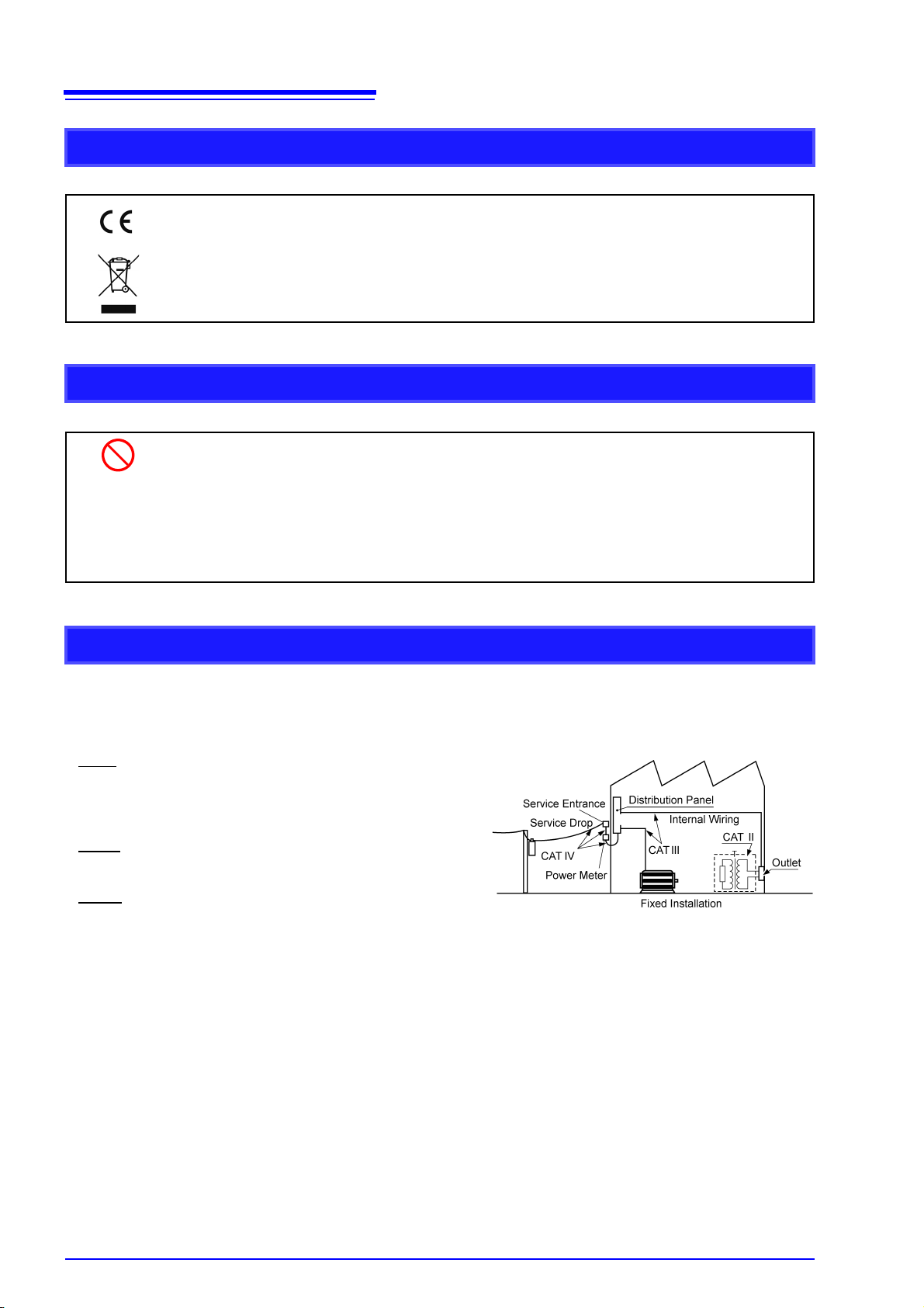
This instrument complies with CAT II safety requirements.
To ensure safe operation of measurement instruments, IEC 61010 establishes safety standards for various electrical
environments, categorized as CAT II to CAT IV, and called measurement categories.
CAT II
: Primary electrical circuits in equipment connected to an
AC electrical outlet by a power cord (portable tools,
household appliances, etc.)
CAT II covers directly measuring electrical outlet receptacles.
CAT III
: Primary electrical circuits of heavy equipment (fixed
installations) connected directly to the distribution panel,
and feeders from the distribution panel to outlets.
CAT IV
: The circuit from the service drop to the service entrance,
and to the power meter and primary overcurrent
protection device (distribution panel).
Using a measurement instrument in an environment designated with a higher-numbered category than that for which
the instrument is rated could result in a severe accident, and must be carefully avoided.
Use of a measurement instrument that is not CAT-rated in CAT II to CAT IV measurement applications could result in
a severe accident, and must be carefully avoided.
Safety Information
Symbols for Various Standards
Indicates that the product conforms to regulations set out by the EU Directive.
WEEE marking:
This symbol indicates that the electrical and electronic appliance is put on the EU market after August 13, 2005, and producers of the Member States are required to display it on the
appliance under Article 11.2 of Directive 2002/96/EC (WEEE).
Other Symbols
Indicates the prohibited action.
(p. ) Indicates the location of reference information.
*
SET
(boldface)
Indicates that descriptive information is provided below.
Text displayed on the instrument is shown in boldface in the manual.
Measurement categories

Operating Precautions
Follow these precautions to ensure safe operation and to obtain the full benefits of the various
functions.
Preliminary Checks
• Before using the instrument for the first time, verify that it operates normally to
ensure that no damage occurred during storage or shipping. If you find any damage, contact your dealer or Hioki representative.
• Before using the instrument make sure that the insulation on the power cord is
undamaged and that no bare conductors are improperly exposed. Using the instrument in such conditions could cause an electric shock, so contact your dealer or
Hioki representative for repair.
• Before using the instrument, make sure that the insulation on cables is undamaged
and that no bare conductors are improperly exposed. Avoid using any cables
showing damage as they may cause electric shock.
5
Operating Precautions
Instrument Installation
Be sure to observe the operating and storage temperature and humidity ranges specified for
the instrument:
• Operating temperature and humidity: 0°C to 40°C, 40% to 80% RH (non-condensing)
• Storage temperature and humidity: -20°C to 55°C, 10% to 80% RH (non-condensing)
The instrument should be installed on a level surface. Use of the device on an inclined surface may prevent readings from being properly recorded or recording paper from folding properly.
Avoid the following locations that could cause an accident or damage to the instrument.
Exposed to direct sunlight
Exposed to high temperature
Exposed to water, oil, other
chemicals, or solvents
Exposed to high humidity
or condensation
Exposed to high levels of
particulate dust
In the presence of corrosive or explosive gases
Exposed to strong electromagnetic fields
Near electromagnetic radiators
Near induction heating systems
(e.g., high-frequency induction
heating systems and IH cooking
utensils)
Subject to vibration

6
Operating Precautions
Handling the Instrument
• Do not allow the instrument to get wet, and do not take measurements with wet
hands. This may cause an electric shock.
• Do not attempt to modify, disassemble or repair the instrument; as fire, electric
shock and injury could result.
• To avoid damage to the instrument, protect it from physical shock when transporting and
handling. Be especially careful to avoid physical shock from dropping.
• Do not slant the device or place it on top of an uneven surface. Dropping or knocking
down the device can cause injury or damage to the device. Install the instrument on a
level surface.
• Do not install the instrument with any side except the bottom facing down. This may
cause a fire or other malfunction in the instrument.
• Exercise care to keep water droplets from accumulating on or getting into the instrument.
Failure to do so may cause the instrument to malfunction.
• Do not apply any oil. Doing so could damage the instrument.
• Never apply any grease or lubricant to the sliding surfaces of the pen holders and the
enclosure.
enclosure.
Doing so could cause a malfunction of the pen operation or damage to the
Operating environment
• This instrument is intended for use indoors.
If you use the instrument in locations with an excessive amount of dust or sand, the pen
operation could malfunction.
Close the front cover, put the drip-proof cover on the instrument, and then load fanfold
paper into the instrument.
Handling pens and recording paper
• Use only genuine Hioki pens and recording paper (p. 33).
• Do not touch pens while recording is in progress.
• Do not use damp recording paper. Doing so may cause the instrument to malfunction.
• Do not reuse recording paper. Doing so may cause the paper to misfeed.
When using fanfold paper
• Ink may run at fold lines. If this running is unacceptable, please use roll paper.
• Paper may not fold properly when used in a very hot, humid environment or when record-
ing waveforms that cover a large percentage of the page. It is recommended to use roll
paper for such applications.
This product may cause interference if used in residential areas. Such use must be avoided
unless the user takes special measures to reduce electromagnetic emissions to prevent
interference to the reception of radio and television broadcasts.

Handling the Cords and Cables
• Avoid stepping on or pinching cables, which could damage the cable insulation.
• To avoid instrument malfunction or damage due to broken connections, do not bend or
pull on the power cord or cables at their base.
Using the Batteries
How to install batteries: "Installing Alkaline Batteries" (p. 17)
• To avoid electric shock, turn off the POWER switch and disconnect the AC adapter
and connection cables before replacing the batteries.
• After replacing the batteries, replace the cover and screws before using the instrument.
• Battery may explode if mistreated. Do not short-circuit, recharge, disassemble or
dispose of in fire.
• Handle and dispose of batteries in accordance with local regulations.
• Keep batteries away from children
7
Operating Precautions
• Do not mix old and new batteries, or different types of batteries. Also, be careful to
observe battery polarity during installation. Otherwise, poor performance or damage from
battery leakage could result.
• Use only the specified type of battery (six LR20 alkaline batteries).
• To avoid corrosion and damage to this instrument from battery leakage, remove the batteries from the instrument if it is to be stored for a long time (for a month).
• After use, always turn OFF the power.
•
You can check the remaining battery life with the LED on the left side of the instrument. (p. 10)
•
The instrument’s Power LED can correctly indicate the remaining battery level only if the
instrument was turned on with unused alkaline batteries inserted.
•
The Power LED color depends on the setting conditions, surrounding temperature, and
remaining battery level. Use of the instrument in a low temperature or that with weak batteries
may cause the instrument to shut down regardless of the Power LED color. Replace batteries
with unused batteries.
Use with manganese batteries
Use with manganese batteries, which cannot generate a large current because of their
small capacity, will cause a shorter operating time.

8
Operating Precautions
Using the AC Adapter
How to connect the adapter:"Connecting the AC adapter" (p. 18)
If you connect the AC adapter while batteries are installed in the instrument, the AC
adapter takes precedence.
• Use only the supplied Model 9418-15 AC Adapter. AC adapter input voltage range is
100 to 240 VAC (with ±10% stability) at 50/60 Hz. To avoid electrical hazards and
damage to the instrument, do not apply voltage outside of this range.
• To avoid electrical accidents and to maintain the safety specifications of this instru-
ment, connect the power cord provided only to a 3-contact (two-conductor +
ground) outlet.
• Turn the instrument off before connecting the AC adapter to the instrument and to
AC power.
• Before turning the instrument on, make sure the supply voltage matches that indi-
cated on the AC adapter. Connection to an improper supply voltage may damage
the instrument or AC adapter and present an electrical hazard.
• For safety reasons, disconnect the power cord when the instrument is not used and
before connecting it to a device to be tested.
• To avoid damaging the power cord, grasp the plug, not the cord, when unplugging it from
the power outlet.
Connecting Cables
• The maximum input voltage is 250 VDC. Attempting to measure voltage in excess
of the maximum input could destroy the instrument and result in personal injury or
death.
• The maximum rated voltage between input terminals and ground is 300 VAC, DC.
Attempting to measure voltages exceeding 300 V with respect to ground could
damage the instrument and result in personal injury.
• To avoid electrical accidents, confirm that all connections are secure. The
increased resistance of loose connections can lead to overheating and fire.
• To avoid experiencing an electric shock or causing a short-circuit at the input terminals, only insulated crimp contacts should be used on wires being connected to
input pins. (The input terminal pin diameter is M6.)
9
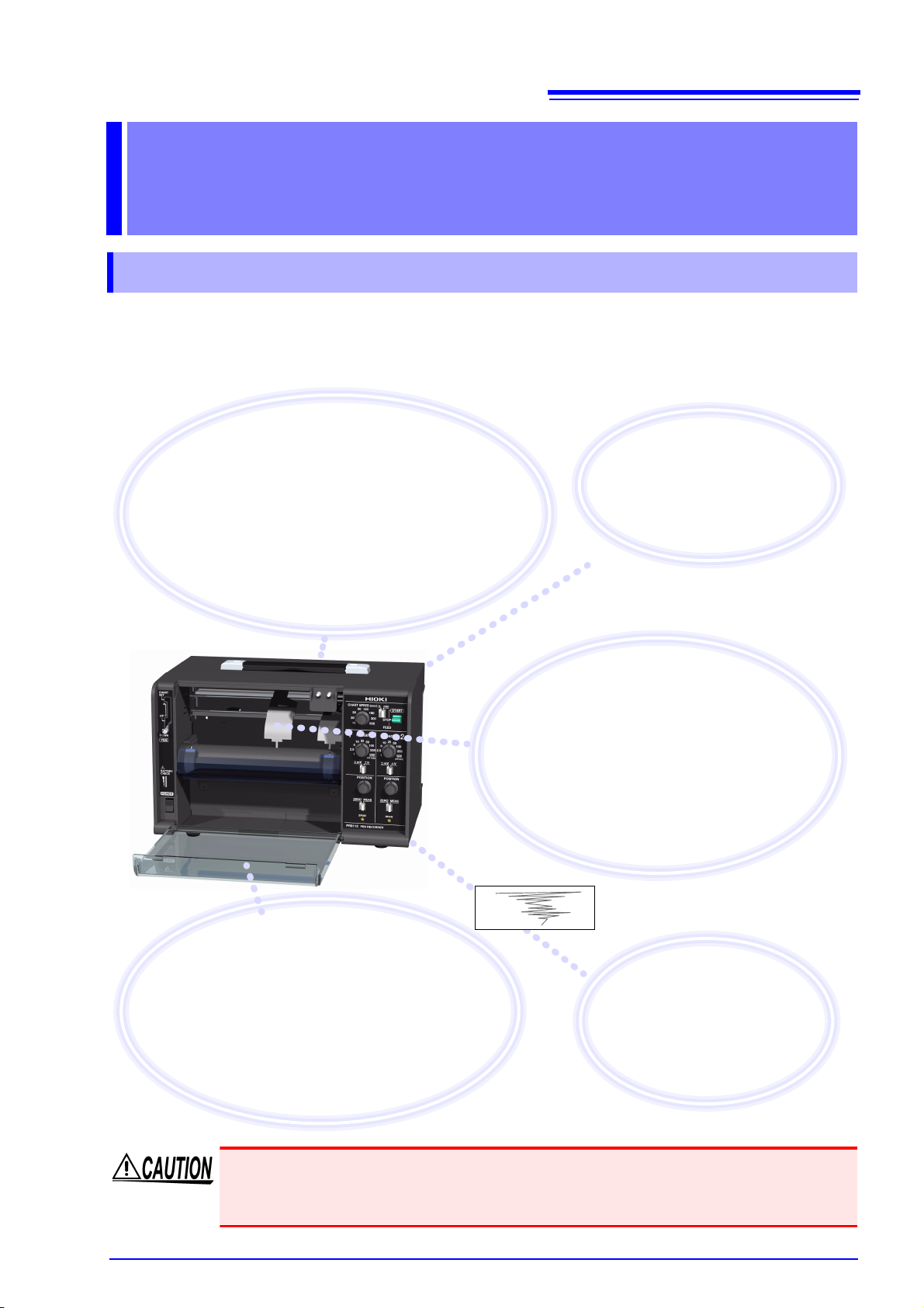
Record, verify, and notate
measurement results in the field
Measurement results are recorded on paper, allowing
them to be easily verified. You can also make notes on the
paper in the field. Additionally, the instrument can measure
voltage output from other equipment, allowing it to be used
in maintenance applications such as corrosion prevention
systems. It can also record analog output, for example
from sensors and physics or chemistry instruments.
Assess changes in easy-to-see
color waveforms by watching
pen movements
The instrument can use red, green, and blue
pens (option). Waveforms are easy to see, even
outdoors, and can be stored for extended periods
of time. Additionally, you can assess waveform
changes in real time simply by watching the instrument’s pens as they move.
Preserve important recordings
Record with the front cover open to protect
recording paper from dirt on the ground.
Record with the front cover closed to keep out
dust and wind.
You can also use the included drip-proof vinyl
cover to protect the instrument from water
droplets and dust.
Select the power source
according
to your location
The instrument can be operated using either the AC adapter or dry-cell
batteries.
Easily compare and
verify results on paper
You can easily discover changes
and abnormalities by comparing
recordings with previously recorded waveforms.
1.1 Product Overview and Features
Overview Chapter 1
1.1 Product Overview and Features
The PR8111 and PR8112 are compact, lightweight, highly portable pen recorders. You can select
from two power sources (AC adapter or dry-cell batteries) according to where the instrument is
being used, assuring your ability to record data immediately and easily with unparalleled reliability,
wherever you are.
1
Operating environment
This instrument is intended for use indoors. If you use the instrument in locations with an
excessive amount of dust or sand, the pen operation could malfunction. Close the front cover,
put the drip-proof cover on the instrument, and then load fanfold paper into the instrument.
10
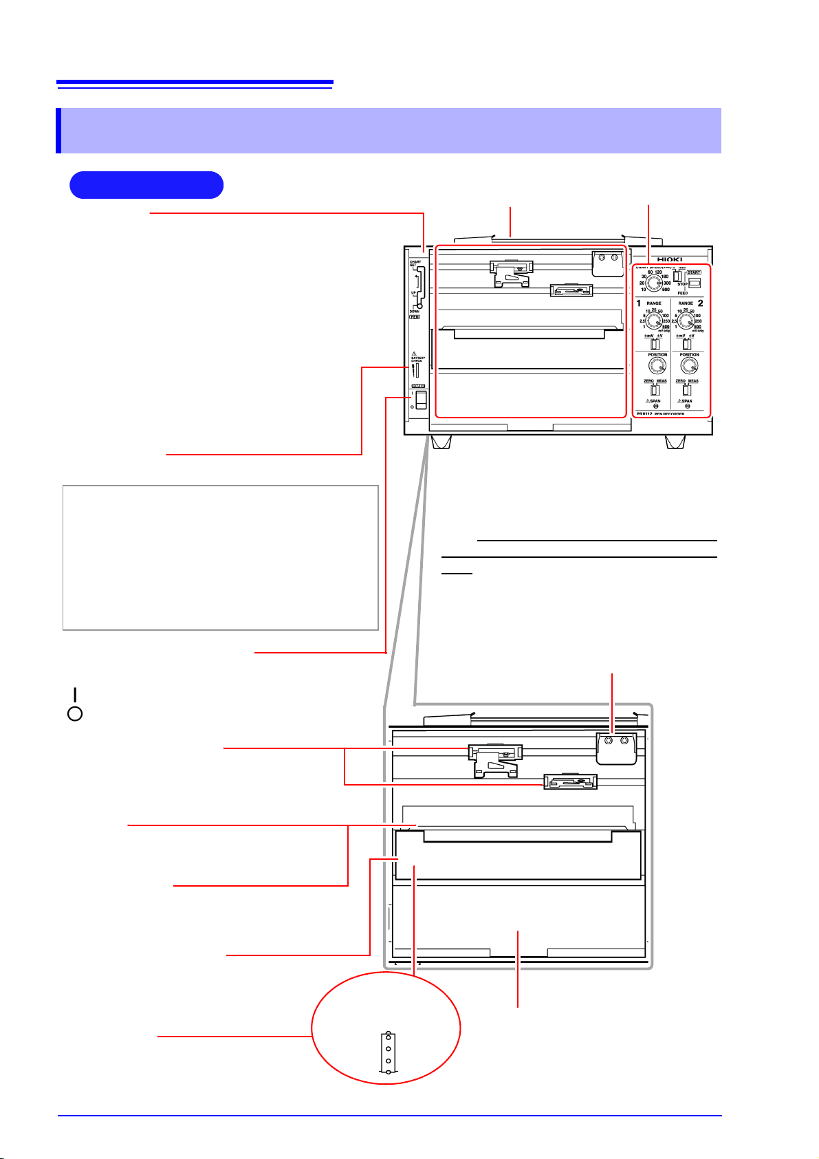
Front Panel
Handle
POWER switch (p. 19)
Turns the power on and off.
:Power OFF
:Power ON
Power LED
Lights up when the instrument is being supplied with power.
Green Lights up when power is being supplied by the
AC adapter. When using batteries, indicates
ample remaining battery life.
Orange Indicates limited remaining battery life. It is rec-
ommend to have new batteries ready to use.
Red Indicates low remaining battery life. It is recom-
mended to replace the batteries in the instrument with new batteries.
Operating panel (p. 11)
Front cover (p. 21)
Keeps wind and dust out of the instrument.
The cover can be removed. It opens from above.
Note: When using roll paper, either remove the
front cover or use the instrument with the cover
open. Recording data with the front cover closed
may cause paper to jam in the chart tray.
(Example: PR8112)
Chart cover (p. 12)
Holds down the recording paper.
Chart holder
(Located underneath the platen)
Stores new recording paper. (p. 14)
Chart tray
Stores paper after waveforms have been
recorded. Fanfold paper will be folded here.
Pen holders (p. 16)
(Located toward the rear of the instrument)
Holds the pens. For more information about
compatible pens, see "Options" (p. 2).
Pen lever
• CHART SET (top)
Use when changing recording paper. The pens
will move up (away from the recording paper) and
to the right.
• UP (middle)
Use when changing pens or to disable recording.
The pens will move up (away from the recording
paper). Cap pens when not recording.
• DOWN (bottom)
Use when recording. The pens will be in contact
with the recording paper, allowing them to record
data.
Pen cap storage pins (p. 16)
Store caps on these pins while the pens are being
used so they don’t get lost.
Platen
Holds down the recording paper.
Sprockets
Feed the recording paper using a series
of holes along its edges.
When the chart
cover is open
1.2 Names and Functions of Parts
1.2 Names and Functions of Parts

11
RANGE knob
Selects the measurement range, allowing
you to choose the range that best suits
the voltage being measured. The 500 setting is used exclusively for mV ranges.
mV/V switch
Selects the unit for the measurement
range selected with the RANGE knob.
POSITION knob
Adjusts the pen’s zero point (0 V position)
by moving its position. When the ZERO/
MEAS switch is in the ZERO position, the
pen can be moved throughout the entire
effective recording width.
ZERO/MEAS switch
• MEAS: Use when measuring data. (You can start recording by placing
the START/STOP/FEED switch in the START position.)
• ZERO: Use when adjusting the pen’s zero point.
(You can move the position with the POSITION knob.)
CHART SPEED knob
Selects the chart speed, allowing you to
change the speed at which the recording
paper is fed through the instrument.
Operating Panel
h/min switch
Selects the unit for the speed set with the CHART SPEED
knob. You can select either minutes (min) or hours (h).
(Example: PR8112)
START/STOP/FEED
switch
Starts and stops the paper feed.
• START: Starts feeding paper through
the instrument.
• STOP: Stops feeding paper through
the instrument.
• FEED (by pushing the switch past
STOP): Feeds paper through the
instrument. There are four feed
speeds. You can increase the feed
speed by pressing and holding the
switch in the FEED position for at
least 2 seconds.
SPAN (p. 12)
Allows the recording width to be adjusted
using a screwdriver. This adjustment is
not usually used during normal operation.
Use as necessary when adjusting the instrument, for example during calibration.
• To increase the width: Turn clockwise.
(The recording width can be
increased by a maximum of about
20%.)
• To decrease the width: Turn counterclockwise. (The recording width can
be decreased by a maximum of about
20%.)
AC adapter terminal (p. 18)
Connect the included AC adapter here.
Battery bay and cover (p. 17)
When using batteries to power the instrument, load six
LR20 alkaline batteries here. Since the battery cover is
held in place with screws (M3), a Phillips head screwdriver is required in order to change the batteries.
FG terminal
Use this terminal, which is connected to the instrument’s
metal chassis, to ground the chassis. For best grounding,
use a cable of 3 m or less in length.
Rear Panel
CH2 POWER switch (p. 26)
Use this switch (available only on the PR8112 [2-pen
model]) to turn CH2 (pen 2) off. Turning off CH2 lowers
the instrument’s power consumption when using only one
channel.
(Example: PR8112)
Input terminals (p. 20)
Connect the measurement cables here.
Red: Connect the cable carrying the high signal.
Black: Connect the cable carrying the low signal.
On the PR8112, the upper two terminals are CH1,
and the lower two terminals are CH2.
The PR8111 has only the upper two terminals.
1.2 Names and Functions of Parts
1

12
1.2 Names and Functions of Parts
SPAN (span adjustment)
This feature is not usually used.
Perform span adjustment during calibration, when you wish to precisely realign the span
(recording paper width) to compensate for the expansion and contraction of the recording
paper, or when you wish to vary the span for other reasons.
The recording width can be adjusted with a precision slotted screwdriver.
• To increase the width: Turn clockwise.
• To decrease the width: Turn counterclockwise.
Adjusting the span causes values to diverge from the calibrated values guaranteed by HIOKI.
After making measurements following span adjustment, have HIOKI or your nearest distributor recalibrate the instrument.
(The recording width can be increased up to 20%.)
(The recording width can be decreased up to 20%.)
Chart cover
As shown below, the chart cover can be opened up to the line indicated by the label.
Do not attempt to push the chart cover beyond the line as doing so may damage it.

2.1 Pre-Operation Inspection
Do not use the instrument if you find any
damage, as doing so may result in an electric shock or short-circuit. Replace the power cord with an undamaged cord.
Yes
Is there any damage to the insulation on
the power cord, exposing metal wire?
1
No
Before using the instrument for the first time, verify that it operates normally to ensure that
no damage occurred during storage or shipping. If you find any damage, contact your dealer
or Hioki representative.
Peripheral Device Inspection
Is there any damage to the insulation on
the measurement cables, exposing metal
wire?
Yes
Do not use the instrument if you find any
damage, as doing so may result in an electric shock. Replace the measurement cables with undamaged cables.
No
If you find any damage, have the instrument
repaired.
Yes
Is there any visible damage to the instrument?
Instrument Inspection
When turning on the instrument
Did the power supply LED (green) light up?
No
2
The power cord may be broken, or the instrument may be experiencing an internal
malfunction. Have the instrument repaired.
If using batteries to power the instrument,
the batteries may be dead, or there may be
no batteries in the instrument.
• If the orange LED is on: Have new batteries ready to use.
• If the red LED is on: Replace the batteries with new batteries.
No
Yes
End of inspection
Be sure to read "Operating Precautions" (p. 5) before using the instrument.
Measurement Preparations Chapter 2
2.1 Pre-Operation Inspection
13
1

14
1 Turn on the POWER switch.
2 Set the pen lever to the CHART SET (top)
position and lock the lever in place by moving
it to the left.
The platen will be raised, and the pens will automat-
ically move to the far right.
3 Hold and shake the recording paper by the
edge to separate the sheets.
4 Load the recording paper into the chart holder
with the round holes on the left and the oval
holes on the right.
(Load so that the side of the paper with the red
marks along the edge is on the bottom.)
5 Open the chart cover, pass the top of the
recording paper through the opening, and pull
the top edge through.
6 Align the paper so that the sprockets engage
the round holes on its left edge.
7 In the same way, align the paper so that the
sprockets engage the oval holes on its right edge.
8 Close the chart cover.
9 Set the pen lever to the UP (middle) position.
The platen will be lowered.
Round
holes
Chart holder
Chart cover
Oval holes
3
4
6,7
Sprockets
2
Pen lever
5
8
Lower the START/STOP/FEED switch to the FEED
position to feed the paper and verify that it has been
properly loaded. You can press and hold the switch in
the FEED position for at least 2 seconds to increase
the feed speed.
9
1
2.2 Loading Recording Paper
2.2 Loading Recording Paper
You can use either fanfold or roll type recording paper in the instrument.
See: "Options" (p. 2)
• Please use only the specified recording paper. Using non-specified paper may not only
result in faulty printing, but printing may become impossible.
• If not loaded properly, recording paper may jam.
• Do not use wet recording paper. Doing so may damage the instrument.
• Do not reuse recording paper. Doing so may prevent the paper from feeding properly.
• Store recording paper at room temperature, taking care to avoid high temperatures and
humidity. Avoid moisture (rain or condensation).
Loading Fanfold Recording Paper

15
2
Pen lever
1
Round
holes
Chart holder
Oval holes
3
1 Turn on the POWER switch.
2 Set the pen lever to the CHART SET (top)
position and lock the lever in place by moving
it to the left.
The platen will be raised, and the pens will automatically move to the far right.
3 Load the recording paper into the chart holder
with the round holes on the left and the oval
holes on the right.
4 Open the chart cover, pass the top of the
recording paper through the opening, and pull
the top edge through.
5 Align the paper so that the sprockets engage
the round holes on its left edge.
6 In the same way, align the paper so that the
sprockets engage the oval holes on its right
edge.
7 Close the chart cover.
8 Set the pen lever to the UP (middle) position.
The platen will be lowered.
Chart cover
5,6
Sprockets
4
7
Lower the START/STOP/FEED switch to the FEED
position to feed the paper and verify that it has been
properly loaded. You can press and hold the switch in
the FEED position for at least 2 seconds to increase
the feed speed.
8
Remaining recording paper
The amount of recording paper remaining (in cm) is indicated on the left edge of the paper.
Red marks will appear on the right side of the paper when there is only about 100 cm of paper left.
2.2 Loading Recording Paper
Loading Roll Recording Paper
1

16
Colors: P-1201 (red), P-1202 (green), P1203 (blue)
The letters A through C are appended to the above part numbers depending on the pen type (speed).
(A: standard; B: high-speed; C: low-speed)
See: "Options" (p. 2)
The P-1201A and P-1202A (PR8112 only) pens that ship with the instrument are the standard “A” type.
Use these pens for general recording work.
• If you need to record at a low paper feed speed of 120 mm/h or less…
Use “C” low-speed type pens (P-1201C, etc.) for less running.
• If you need to record at a high speed or want the waveform to dry more quickly…
Use “B” high-speed type pens (P-1201B).
1 Set the pen lever to the UP (middle)
position.
The pens will be raised from the recording
paper.
2 Firmly insert the pen as far as it will go
into the pen holder.
Verify that the pen has been inserted as
far as it will go.
3 Remove the pen cap and place it on
the pen cap storage pin.
Pull the cap toward you away from the
pen to remove it.
Pen lever
Pen holder
Pen cap storage
pins
1
2
Return the pen caps to the pen tips after
use to keep the pens from drying out.
For the PR881 (2-pen model), the forward (upper) pen holder is CH1, and the rearward (lower) pen holder is CH2.
3
Viewed from side
2.3 Installing the Pens
2.3 Installing the Pens
Use only genuine HIOKI P-1200 series felt pens in the instrument.
• Be sure to stop pen operation before attempting to install or replace pens. Do not apply
excessive force to the pens during recording. Doing so may damage the instrument.
• After use, recap each pen. Leaving the pens uncovered may cause the pen tip to dry out,
making it impossible to record waveforms.
• Never apply any grease or lubricant to the sliding surfaces of the pen holders and the
enclosure. Doing so could cause a malfunction of the pen operation or damage to the
enclosure.
• Once a pen has run out of ink, developed a thick tip, or grown too short, it cannot be used
anymore. Replace it with a new pen.
• Store unused pens at room temperature, avoiding high temperature and humidity.
• Dispose of used pens in accordance with local regulations.
• Lines drawn with A-type and C-type pens are less prone to dry at a low temperature.
• If ink could bleed through a sheet of fanfold recording paper, use a B-type pen or roll-type
recording paper instead.
Installing Pens and Using the Pen Caps

17
Checking the remaining battery life
You can check how much battery life remains with the Power LED.
Green Indicates ample remaining battery life.
(Also lights up when powering the instrument with the AC adapter.)
Orange Indicates limited remaining battery life. It is recommend to have new batteries ready to use.
Red Indicates low remaining battery life.
It is recommended to replace the batteries in the instrument with new batteries.
Estimated operating times
• PR8111 (1-pen model): Approx. 50 hours
• PR8112 (2-pen model): Approx. 25 hours
When using the PR8112 (2-pen model) with just one pen, you can set the CH2 POWER switch on the
rear of the instrument to OFF to realize similar operating times as for the PR8111 (1-pen model).(p. 26)
Before installing batteries into the instrument, be sure to read "Using the Batteries" (p. 7).
Required: One Phillips head screwdriver, six LR20 alkaline batteries
1 Turn off the POWER switch.
If the instrument is connected to the AC adapt-
er and cables, disconnect them.
2 Use the screwdriver to remove the screws
holding the battery cover in place on the
back of the instrument and remove the
battery cover.
3 Install six new LR20 alkaline batteries.
4 Reattach the battery cover and tighten it
securely in place with the screws
removed in step (2) above.
The battery cover is held in place by M3-size screws.
To ensure safe operation, affix the battery cover with
screws. Avoid mixing new and old batteries or different types of batteries. Note the positive and negative
poles and exercise care not to install the batteries
backwards. Doing so may result in degraded performance or cause the batteries to leak.
2.4 Connecting the Power Source (Alkaline Batteries or AC Adapter)
2.4 Connecting the Power Source (Alkaline
Batteries or AC Adapter)
You can power the instrument with either mains power or batteries, depending on where you’re
using it. If you use mains power while batteries are installed in the instrument, the AC adapter takes
precedence.
Installing Alkaline Batteries
When you are unable to operate the instrument using mains power, you can power it with six LR20
alkaline batteries instead. The batteries will also serve as a backup power source in the event of a
power outage when using mains power.
1

18
Before connecting the AC adapter, be sure to read "Using the AC Adapter" (p. 8) and
"Handling the Cords and Cables" (p. 7).
Rated supply voltage is 100 to 240 VAC, and rated supply frequency is 50 or 60 Hz.
1
2
3
Power cord
AC adapter
1 Connect the power cord to the inlet socket
on the AC adapter.
2 Connect the output plug of the AC adapter
to the instrument.
3 Plug the power cord into the mains outlet.
Rear panel
2.4 Connecting the Power Source (Alkaline Batteries or AC Adapter)
Connecting the AC adapter
Connect the Model 9418-15 AC Adapter and power cord that came with the instrument and then
connect the power cord to a wall outlet. When the adapter is used along with alkaline dry-cell batteries, the AC adapter takes precedence. If the supply of power from the AC adapter is interrupted, the
instrument will switch over to battery power. When power returns, it will automatically revert to
power from the AC adapter.
Using a DC Power Source
You can also use the instrument with DC power source input, for example from an external battery.
The instrument can be powered with a 10 to 27 VDC signal from the AC adapter jack. Hioki can provide cables for this purpose on a special-order basis. For more information, please contact your
dealer or Hioki representative.
The cable connecting the battery and instrument should not exceed 3 m in length.

19
Power ON
Power OFF
Turning on the instrument
Turn the POWER switch to the ON position.
Once the instrument has been turned on, the power supply LED will
light up.
Green Lights up when power is being supplied by the AC adapt-
er. When using batteries, indicates ample remaining bat-
tery life.
Orange Indicates limited remaining battery life. It is recommend to
have new batteries ready to use.
Red Indicates low remaining battery life. It is recommended to
replace the batteries in the instrument with new batteries.
Turning off the instrument
Turn the POWER switch to the OFF position.
If the orange or red LED lights up while using the AC adapter, the
instrument may be damaged. Stop all use and have the unit
repaired.
2.5 Turning the Instrument On and Off
2.5 Turning the Instrument On and Off
Once you have connected the instrument to its power supply or loaded batteries, you can turn the
instrument on.
1

20
Before connecting cables, be sure to read "Connecting Cables" (p. 8) and "Handling the
Cords and Cables" (p. 7).
CH1
(PR8112)
The PR8111 does not have terminals for CH2.
• When you input a signal such that the red (H) terminal has a higher potential than the black (L)
terminal, the pen moves rightward, starting from the user-specified zero point.
• When you input a signal such that the red (H) terminal has a lower potential than the black (L)
terminal, the pen moves leftward, starting from the user-specified zero point.
CH2
2.6 Connecting Measurement Cables to the Input Terminals
2.6 Connecting Measurement Cables to the
Input Terminals
Connect the measurement cables to the measurement terminals on the rear of the instrument.
Wires with either crimp terminals or banana-plug cables can be connected.
• The maximum input voltage is 250 VDC. Attempting to measure voltage in excess
of the maximum input could destroy the instrument and result in personal injury or
death.
• The maximum rated voltage between input terminals and ground is 300 VAC, DC.
Attempting to measure voltages exceeding 300 V with respect to ground could
damage the instrument and result in personal injury.
To avoid experiencing an electric shock or causing a short-circuit at the input terminals, only insulated crimp contacts should be used on wires being connected to
input pins. (The input terminal pin diameter is M6.)
How to connect cables

21
Attaching the front cover
Insert the pegs on the cover into the
grooves on the instrument while inclining
the cover at an angle of about 60 from the
horizontal.
Detaching the front cover
Remove the pegs on the cover from the
grooves on the instrument while inclining
the cover at an angle of about 60 from the
horizontal.
2.7 Attaching and Detaching the Front Cover
2.7 Attaching and Detaching the Front Cover
You can keep wind, dust, and other foreign matter out of the instrument by attaching the front cover,
which also prevents recording paper from becoming entangled. The cover also protects the measurement hardware when the instrument is being shipped or transported.
When using roll paper, either detach the front cover or use the instrument with the cover
open. Recording data with the front cover closed may cause paper to jam in the chart tray.
1
Operating environment
This instrument is intended for use indoors.
If you use the instrument in locations with an excessive amount of dust or sand, the pen operation could malfunction.
Close the front cover, put the drip-proof cover on the instrument, and then load fanfold paper
into the instrument.

22
Place the cover over the instrument,
positioning it so that the side that can be
opened and closed covers the front of the
device.
2.8 Attaching the Drip-proof Vinyl Cover
2.8 Attaching the Drip-proof Vinyl Cover
The drip-proof cover can keep the instrument and recording paper from getting wet when using the
device in light rain or locations such as tunnels where dripping water is a concern. It can also help
keep dust, sand, and other foreign matter out of the instrument.
The instrument can be carried with the drip-proof cover on it. Convenient zippers let you easily
check and replace recording paper.
Operating environment
This instrument is intended for use indoors.
If you use the instrument in locations with an excessive amount of dust or sand, the pen operation could malfunction.
Close the front cover, put the drip-proof cover on the instrument, and then load fanfold paper
into the instrument.

3.1 Configuration and Measurement Process
Place the pen lever in the UP position
(middle) and cap the pens (p. 25)
Remove the recording paper (p. 25)
Stop measurement (STOP) (p. 25)
Start measurement (START) (p. 25)
Place the pen lever in the DOWN position
(bottom) to lower the pens (p. 24)
Set the paper feed speed
(CHART SPEED) (p. 24)
Move the pen position (POSITION)
(p. 24)
Select a measurement range (RANGE)
(p. 24)
As much as possible, avoid printing in hot and humid environments. Otherwise, printer life
may be severely shortened.
Configuring the Instrument and Taking Measurements Chapter 3
3.1 Configuration and Measurement Process
23
1

24
1 Select the units with the mV/V switch.
2 Rotate the RANGE knob to select the desired range.
You can select the best range for the voltage you intend to measure. The range can be set from ±1 mV to ±250 V. The 500 setting is used exclusively for mV ranges.
Do not set the RANGE knob to 500 while the mV/V
switch is set to V.
1 Move the ZERO/MEAS switch to the ZERO position.
2 Rotate the POSITION knob to set the pens’ zero points.
You can adjust the pen zero point and move the pen position.
You can set the zero point (0 V position) by moving the ZERO/
MEAS switch in the ZERO position.
Example: When using the ±1 mV range, centering the zero point
allows you to measure from -1 mV to +1 mV, while placing it at
the leftmost edge allows you to measure from 0 V to +2 mV.
You can set the paper feed speed according to the desired recording
time. This setting can be changed while recording is in progress.
1 Select the speed unit with the h/min switch.
• mm/h: Amount of paper feed per hour [mm]
• mm/min: Amount of paper feed per minute [mm]
2 Rotate the CHART SPEED knob to select the desired
speed.
(Example: 300 mm/h)
Place the pen lever in the DOWN (bottom) position
to lower the pens.
3.2 Basic Measurement
3.2 Basic Measurement
Select a Measurement Range (RANGE)
Move the Pen Position (POSITION)
Set the Paper Feed Speed (CHART SPEED)
Lower the Pens (pen lever)

25
1 Move the ZERO/MEAS switch to the MEAS position.
The pens will move in response to input signals.
2 Move the START/STOP/FEED switch to the START position.
Paper will be fed through the instrument, and recording will start.
1 Move the START/STOP/FEED switch to the STOP position to
stop feeding paper through the instrument.
Paper will stop moving through the instrument.
2 Place the pen lever in the UP (middle) position to raise the
pens.
If you’re using fanfold paper, tear off the paper along the perforated line.
To feed paper through the instrument
You can use the START/STOP/FEED switch to feed paper through the in-
strument.
Moving the switch to the FEED position causes paper to be fed
through the instrument. There are four feed speeds. When you
press and hold the switch in the FEED position for at least 2
seconds, the feed speed will increase.
Lift each pen toward you and cap it.
3.2 Basic Measurement
Start Measurement
Stop Measurement
1
Remove the Recording Paper
Cap the Pens

26
Move the CH2 POWER switch on the rear
of the instrument to the OFF position.
Only the CH1 pen will operate.
Cap the CH2 pen before starting measure-
ment. Taking measurements with the CH2
pen uncapped may cause the position of
the CH2 pen tip to be recorded on the re-
cording paper.
3.3 Using Only One channel (PR8112 Only)
3.3 Using Only One channel (PR8112 Only)
When using only CH1, you can limit the instrument’s power consumption to the power necessarily to
drive one channel by setting the CH2 POWER switch on the rear of the instrument to OFF, thereby
turning off the CH2 power supply. When powering the instrument with batteries, doing so will
lengthen the batteries’ service lifetime compared to when the CH2 POWER switch is ON.

27
Indicates the amount of recording paper remaining (unit: cm).
Example of data recorded with the PR8112
3.4 Example Printout
3.4 Example Printout
1

28
3.4 Example Printout

Chapter 4 Specifications
Specifications Chapter 4
Chapter 4 Specifications
Product Configurations
1-pen model Model PR8111
2-pen model Model PR8112
Basic Specifications
Operating method Self-balancing
No. of pens PR8111: 1 pen; PR8112: 2 pens
29
1
Input DC voltage
Recording method Disposable felt pens
Measurement ranges ±1 mV, 2.5 mV, 5 mV, 10 mV, 25 mV, 50 mV, 100 mV, 250 mV, 500 mV,
1 V, 2.5 V, 5 V, 10 V, 25 V, 50 V, 100 V, 250 V
17 ranges
Effective recording width 150 mm
Recording accuracy ±0.5% of effective recording width (including linearity in reference range; refer-
ence range of 250 mV)
Excludes recording paper contraction and expansion.
Dead zone ±0.2% of effective recording width
Inter-range error ±0.25% of effective recording width
Temperature
characteristics
Accuracy guarantee
period
Input resistance 2 MΩ ±1%
Pen interval 5 mm ±1 mm
Pen speed 500 mm/sec or faster (using AC adapter)
±0.1% of effective recording width per 1°C
1 year
Chart speed 10 mm, 20 mm, 30 mm, 60 mm, 120 mm, 180 mm, 300 mm, 600 mm/min
10 mm, 20 mm, 30 mm, 60 mm, 120 mm, 180 mm, 300 mm, 600 mm/h
16 ranges
Chart speed accuracy ±0.25%
Zero point movement
range
Chart feed 300 mm/min slow-up method
Pen-lifting mechanism Gang lift
Orientation Vertical
Can be adjusted throughout area for each range.

30
Chapter 4 Specifications
Recording paper • Fanfold recording paper SE-10Z-2 (length: 15 m)
• Roll recording paper SE-10 (length: 20 m)
Maximum rated voltage
between terminals
Maximum rated voltage
between terminals and
ground
Dielectric strength and
insulation resistance
Battery check 3-stage LED display (green, orange, red) (when operating on battery power)
Operating temperature
and humidity
Storage temperature and
humidity
Operating environment Indoors, pollution degree 2, up to 2,000 m ASL
Dimensions Approx. 292W × 177H × 182D mm (11.50”W × 6.97”H × 7.17”D)
Mass PR8111: Approx. 3.9 kg (137.6 oz) (instrument only)
250 VDC (V ranges) or 30 VDC (mV ranges)
300 VAC, DC, measurement category II;
anticipated transient overvoltage: 2,500 V
(Between input channels and instrument or between input channels)
3.0 kVAC for 1 min, 50 MΩ or more at 500 VDC
(Between input channels and instrument or between input channels)
Accuracy is guaranteed even when red indicator is lit.
(green→orange: 6.9 V±0.15 V, orange→red: 6.4 V±0.15 V)
Temperature: 0°C to 40°C (32°F to 104°F)
Humidity: 40% to 80% RH (non-condensing)
Temperature: -20°C to 55°C (-4°F to 131°F)
Humidity: 10% to 80% RH (non-condensing)
(excluding protruding parts)
PR8112: Approx. 4.4 kg (155.2 oz) (instrument only)
Power source Model 9418-15 AC Adapter (12 VDC)
Rated supply voltage: 100 to 240 VAC (with allowance for 10% voltage fluctu-
ations)
Rated supply frequency: 50/60 Hz
Anticipated transient overvoltage: 2,500 V
DC power supply input: 10 to 27 VDC (Input can be provided to the AC adapter
jack via a special-order cable connected.)
Wiring between battery and the instrument must be 3 m or less in length.
Dry-cell batteries: Six LR20 alkaline batteries
(When used with the AC adapter, the adapter takes precedence.)
Max. rated power 4 VA (AC adapter, DC power supply) or 3 VA (dry-cell batteries)
Continuous operating time When using LR20 alkaline batteries (reference values for 23°C)
PR8111: Approx. 50 hours
PR8112: Approx. 25 hours
Test conditions: 60 mm/h chart speed, ±250 mV measurement range, 400
mVp-p 0.01 Hz sine wave input waveform
Applicable standards Safety: EN61010
EMC: EN61326 Class A
Effect of radiated radiofrequency electromagnetic field
±2% of effective recording with at 10 V/m
Effect of conducted radiofrequency electromagnetic
field
±2% of effective recording width at 3 V

Accessories
31
Chapter 4 Specifications
Felt pens PR8111: P-1201A (red)
PR8112: P-1201A (red), P-1202A (green)
Recording paper SE-10Z-2 (fanfold paper) 1
AC adapter 9418-15
Instruction manual 1
Drip-proof vinyl cover 1
Front cover 1
Accessories sold separately
Felt pens Red : P-1201A (standard), P-1201B (high-speed), P-1201C (low-speed)
Green: P-1202A (standard), P-1202B* (high-speed), P-1202C (low-speed)
Blue : P-1203A (standard), P-1203B* (high-speed), P-1203C (low-speed)
*: Discontinued product
Recording paper SE-10Z-2 (fanfold paper), SE-10 (roll paper)
AC adapter 9418-15
1

32
Chapter 4 Specifications

5.1 Inspection, Repair, and Cleaning
Maintenance and Service Chapter 5
5.1 Inspection, Repair, and Cleaning
Do not attempt to modify, disassemble or repair the instrument; as fire, electric shock
and injury could result.
33
1
Transporting
Observe the following precautions to avoid damaging the instrument:
• Use the original packing materials when transporting the instrument, if possible.
• When sending the instrument for repair, remove the batteries and pack carefully to prevent damage in transit. Include cushioning material so the instrument cannot move within
the package. Be sure to include details of the problem. Hioki cannot be responsible for
damage that occurs during shipment.
• Remove pens and recording paper when transporting the instrument. Failure to do so
may damage the hardware in the instrument that accommodates the pens and recording
paper due to vibrations. Be sure to cap the pens.
Storing the Instrument
• To avoid corrosion and damage to this instrument from battery leakage, remove the batteries from the instrument if it is to be stored for a long time (for a month). For more information about batteries, see "2.4 Connecting the Power Source (Alkaline Batteries or AC
Adapter)" (p. 17).
• Cap pens after use. Leaving pens uncapped may cause their tips to dry out, making it
impossible to record waveforms. When not being used, pens should be stored at room
temperature, avoiding high heat and humidity. For more information about storing pens,
see "2.3 Installing the Pens" (p. 16).
• Do not leave the front cover detached or open. Doing so could allow dust to enter the
instrument, resulting in damage to the instrument. If the instrument will not be used for an
extended period, put the drip-proof vinyl cover on the instrument to prevent dust from
entering.
For more information about storing recording paper, see "2.2 Loading Recording Paper" (p. 14).

34
5.1 Inspection, Repair, and Cleaning
Replaceable Parts and Operating Lifetimes
Useful life depends on the operating environment and frequency of use. Operation cannot be guaranteed beyond the following periods. For replacement parts, contact your dealer or Hioki representative.
Part Life
Electrolytic Capacitors Approx. 10 years
The fuse is housed in the power unit of the instrument. If the power does not turn on, the fuse may be blown.
If this occurs, a replacement or repair cannot be performed by customers. Please contact your dealer or Hioki
representative.
Maintenance
To clean the instrument, wipe it gently with a soft cloth moistened with water or mild detergent.
Never use solvents such as benzene, alcohol, acetone, ether, ketones, thinners or gasoline, as they
can deform and discolor the case.
• Do not apply any oil. Doing so could damage the instrument.
• Never apply any grease or lubricant to the sliding surfaces of the pen holders and the
enclosure. Doing so could cause a malfunction of the pen operation or damage to the
enclosure.

35
5.2 Troubleshooting
5.2 Troubleshooting
If damage is suspected, check the "Before Returning for Repair" section before contacting your
dealer or Hioki representative.
Before Returning for Repair
Symptom Check Items
The LED (on the left
side of the instrument) doesn’t turn on
when the POWER
switch is turned on.
The pens don’t move
when the control
panel is operated.
Paper is not being
fed through the instrument.
Has the power cord been disconnected? Is it connected properly?
Are the batteries installed properly? Verify that the batteries have been installed
Is the CH2 POWER switch in the OFF
position (PR8112)?
Has the recording paper come off the
sprockets?
Verify that the power cord is properly connected to the outlet and the AC adapter (p.
18).
properly (p. 17).
The CH2 pen will operate when the CH2
POWER switch is in the ON position.
Verify that the recording paper has been
loaded properly (p. 14).
If the paper is not being fed through the instrument even though it has been loaded
properly, the instrument may be damaged.
Please contact your dealer or Hioki representative.
1
Are you trying to reuse recording paper?
The instrument won’t
turn on.
The waveform is not
changing.
Nothing prints on the
paper.
Printout is too light. The pens may have dried out. Replace the pens.
A power protection component may
be damaged.
Are the cables connected properly? Verify that the measurement and other ca-
Is the measurement range set properly?
Is the ZERO/MEAS switch set to the
MEAS position?
Are the recording paper and pens installed properly?
Is the paper lever in the DOWN (bottom) position?
Do not attempt to reuse recording paper.
Additionally, use only genuine Hioki recording paper.
Customers should not attempt to replace or
repair parts. Contact your dealer or Hioki
representative for service.
bles are connected properly.
Verify that the RANGE knob and the mV/V
switch have been set appropriately.
Verify that the ZERO/MEAS switch is set to
the MEAS position and that the START/
STOP/FEED switch is set to the START po-
sition.
Verify that the recording paper (p. 14) and
pens (p. 16) are installed properly.
The pens will be in contact with the recording paper when the paper lever is in the
DOWN (bottom) position.
Ink is leaking from
the pens.
Are the pens being stored properly? Store pens at room temperature, avoiding
high temperature and humidity.

36
PR8111 PR8112
292±5
182±5 182±5
177±5
(mm)
292±5
177±5
Top Bottom
Right Left
Rear
Front
5.3 Outline Drawings
5.3 Outline Drawings

1


 Loading...