

Page 1
99 Washington Street
Melrose, MA 02176
Phone 781-665-1400
Visit us at www.TestEquipmentDepot.com
Toll Free 1-800-517-8431
PD3259
Instruction Manual
DIGITAL PHASE DETECTOR
Jan. 2016 Edition 1
PD3259A981-00 16-01H
XXXXXXX
SAMPLE
右:9 mm 以上、下:5 mm 以上あける
EN
Page 2

Contents
Introduction .........................................................................1
Verifying Package Contents
Options (Sold Separately)
Safety Information
Operating Precautions
.............................................................. 2
.............................................. 1
..................................................2
....................................................... 7
1 Overview 11
1.1 Overview and Features ................................. 11
1.2 Part Names and Functions ........................... 12
1.3 Battery Level .................................................. 15
2 Preparing for Measurement 17
2.1 Measurement Process .................................. 17
2.2 Attaching Color Spirals and Bundling
Cables Together ............................................18
2.3 Attaching the Magnetic Strap (Optional) ....19
2.4 Installing and Replacing Batteries ..............20
2.5 Inspecting the Instrument ............................21
2.6 Turning the Instrument On and Off ..............22
2.7 Attaching the Voltage Sensors to the
Circuit ............................................................. 23
2.8 Setting Up the Instrument in the
Measurement Location ................................. 26
3 Performing Measurement 27
3.1 Measuring Line Voltages in a 3-phase
Circuit ............................................................. 28
3.2 Checking Phase Order in a 3-phase
Circuit (Phase Detection Function) .............30
PD3259A981-00
i
Page 3

Contents
3.3 Measuring Frequency ................................... 31
4 Convenient Uses 33
4.1 Power-on Options .........................................33
Auto power-off function ............................................. 35
Disabling the auto-power-off function .......................36
Switching the phase display (phase display
switching function) ....................................................37
Enabling and disabling the beep function ................. 38
Checking the version and serial number ..................39
4.2 Holding the Display ....................................... 40
Enabling and disabling the hold function .................. 40
4.3 Turning On the Backlight ..............................41
Enabling and disabling the backlight ........................41
4.4 Displaying the Predicted State for a
3-phase Circuit ..............................................42
5 Specification 43
5.1 GeneralSpecification .................................43
5.2 InputSpecification andMeasurement
Specification ................................................ 44
Accuracy specification ............................................45
5.3 FunctionalSpecification ............................. 45
5.4 OtherSpecification .....................................46
6 Maintenance and Service 47
6.1 Repair, Inspection, and Cleaning .................47
6.2 Troubleshooting ............................................48
Error codes ...............................................................51
ii
Page 4

Contents
Appendix Appx.1
Appx. 1 About 3-phase Circuits ....................Appx.1
Appx. 2 About the Instrument’s Voltage
Sensors..............................................Appx.2
Index Ind.1
iii
Page 5
Introduction
Introduction
Thank you for choosing the Hioki PD3259 Digital Phase Detector.
To obtain maximum performance from the instrument, please read
this manual first, and keep it handy for future reference
Verifying Package Contents
Once you have received the instrument, verify that it has not
suffered any damage during shipment before using it.
Pay particular attention to the accessories, panel keys, and cables.
If damage is evident, or if it fails to operate according to the
specifications, contact your authorized Hioki distributor or reselle .
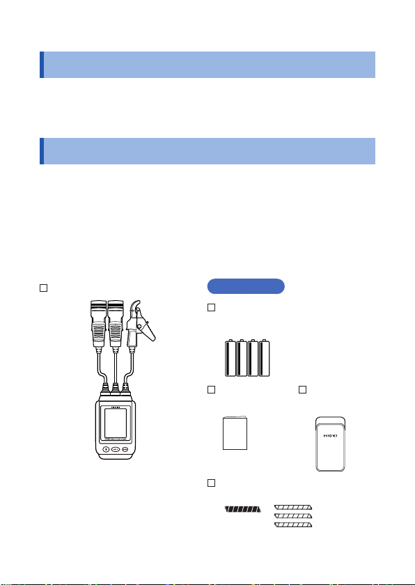
Confirm that these contents are provided
PD3259 Digital Phase Detector
Accessories
LR6 (AA-size) alkaline batteries
× 4
Instruction
manual
Spiral tubes
(black, red, blue, yellow)
Carrying
case
1
Page 6
Options (Sold Separately)
Options (Sold Separately)
The following options are available for this instrument. Contact your
authorized Hioki distributor or reseller when ordering.
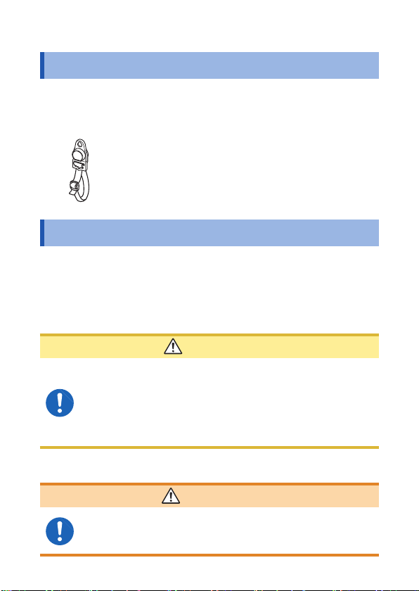
Z5020 Magnetic Strap (p. 19)
The magnetic strap can be used to attach the instrument
to a wall, such as a metal surface.
Safety Information
This instrument is designed to conform to IEC 61010 Safety
Standards, and has been thoroughly tested for safety prior to
shipment. However, using the instrument in a way not described in
this manual may negate the provided safety features. Before using
the instrument, be certain to carefully read the following safety notes.
CAUTION
• Mishandling during use could cause damage to
the instrument. Be certain that you understand the
instructions and precautions in the manual before use.
• Individuals using an electrical measuring instrument for
the first time should be supervised by a technician who
has experience in electrical measurement.
Protective gear
This instrument measures live lines. To prevent
electric shock, use appropriate protective insulation
and adhere to applicable laws and regulations.
2
WARNING
Page 7
Safety Information
Safety-related notations
In this manual, the risk seriousness and the hazard levels are
classified as follows
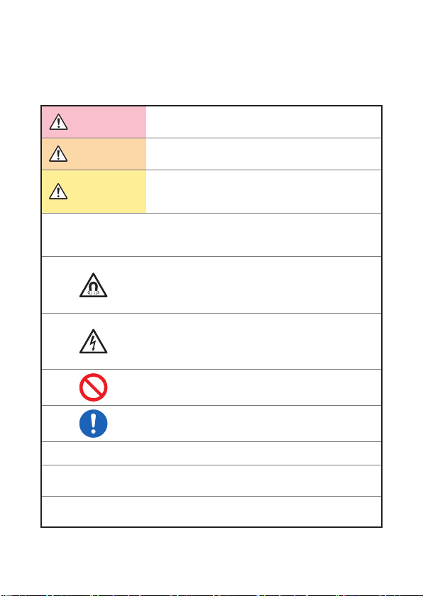
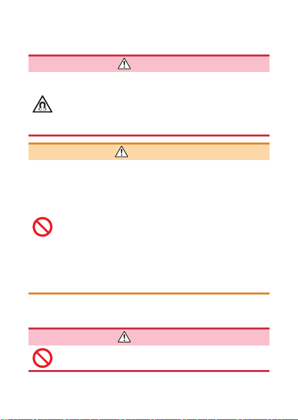
DANGER
WARNING
CAUTION
IMPORTANT
Indicates an imminent hazard that could lead to
serious injury or death.
Indicates a hazard that could lead to serious injury
or death.
Indicates a hazard that could lead to minor injury
or that could be expected to result in equipment or
other damage.
Indicates information related to the operation of the
instrument or maintenance tasks with which the
operators must be fully familiar.
Indicates a strong magnetic-field hazard
The effects of the magnetic force can cause
abnormal operation of heart pacemakers and/or
medical electronics.
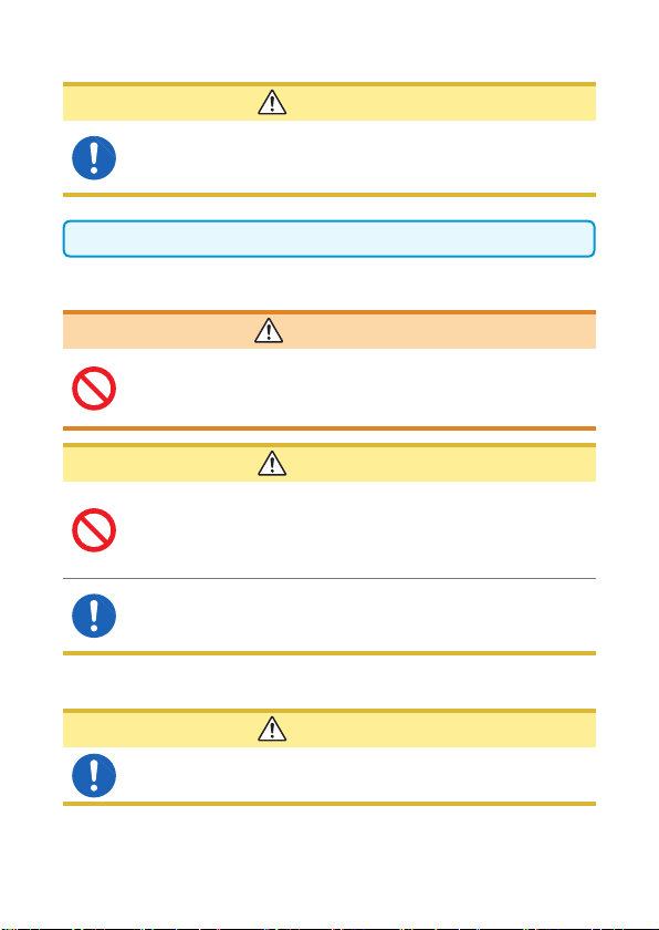
Indicates a high-voltage hazard.
Warns that failure to verify safety or improper use of
the instrument could lead to electric shock, burns,
or death.
Indicates a prohibited action.
Indicates the action which must be performed.
*
[ ]
MODE
(Bold font)
Additional information is presented below.
Names of items on screens are enclosed in
parentheses ([ ]).
Alphanumeric characters shown in bold indicate the
characters that appear on the control keys.
3
Page 8
Safety Information
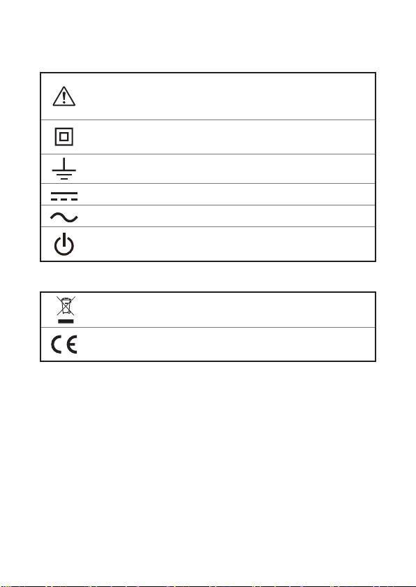
Symbols displayed on the instrument
Indicates cautions and hazards. When the symbol is printed on
the instrument, refer to a corresponding topic in the Instruction
Manual.
Indicates an instrument that is completely protected by double
insulation and reinforced insulation.
Indicates the grounding terminal.
Indicates DC (Direct Current).
Indicates AC (Alternating Current).
Indicates the power supply’s “on” and “off” positions.
Symbols for various standards
Indicates the Waste Electrical and Electronic Equipment
Directive (WEEE Directive) in EU member states.
Indicates that the product conforms to regulations set out by the
EC Directive.
4
Page 9
Safety Information
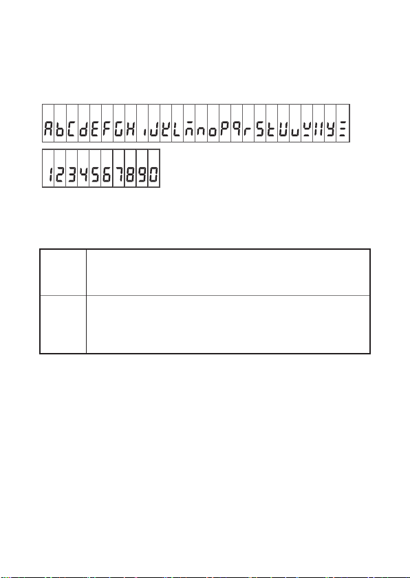
Characters in screen displays
The screen of this instrument displays characters in the following
manner.
A B C D E F G H I J K L M N O P Q R S T U V W X Y Z
1 2 3 4 5 6 7 8 9 0
Accuracy
We define measurement tolerances in terms of rdg. (reading) and
dgt. (digit) values, with the following meanings:
(Reading or displayed value)
rdg.
The value currently being measured and indicated on the
measuring instrument.
dgt. (resolution)
The smallest displayable unit on a digital measuring instrument,
dgt.
i.e., the input value that causes the digital display to show a “1”
as the least-significant digit
5
Page 10
Safety Information
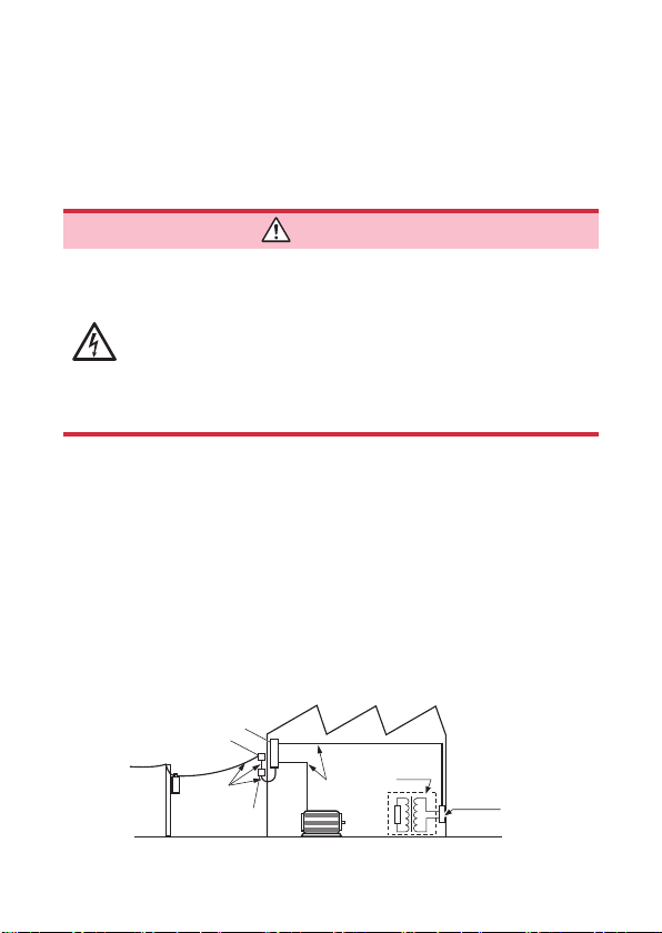
Measurement categories
To ensure safe operation of measurement instruments, IEC 61010
establishes safety standards for various electrical environments,
categorized as CAT II to CAT IV, and called measurement
categories.
DANGER
• Using a measuring instrument in an environment
designated with a higher numbered category than
that for which the instrument is rated could result in
a severe accident, and must be carefully avoided.
• Using a measuring instrument without categories in
an environment designated with the CAT II to CAT
IV category could result in a severe accident, and
must be carefully avoided.
This instrument conforms to the safety requirements for CAT IV 600 V
measuring instruments.
CAT II: When directly measuring the electrical outlet receptacles of the
CAT III: When measuring the primary electrical circuits of heavy equipment
CAT IV: When measuring the circuit from the service drop to the service
primary electrical circuits in equipment connected to an AC electrical
outlet by a power cord (portable tools, household appliances, etc.)
(fixed installations) connected directly to the distribution panel, and
feeders from the distribution panel to outlets
entrance, and to the power meter and primary overcurrent
protection device (distribution panel)
Distribution panel
Service entrance
Service drop
CAT IV
Power meter
Internal wiring
CAT III
Fixed installation
CAT II
T
Outlet
6
Page 11
Operating Precautions
Operating Precautions
Follow these precautions to ensure safe operation and to obtain the
full benefits of the various functions
WARNING
Do not use the instrument beyond its rated and
specificatio ranges.Doingsomayresultindamage
to the instrument or electric shock.
Before using the instrument, check the instrument for any damage
that may have been sustained while in storage or transit, inspect it,
and verify that it is operating properly. If you find any faults, contact
your authorized Hioki distributor or reseller.
This instrument may cause interference if used in residential
areas. Such use must be avoided unless the user takes special
measures to reduce electromagnetic emissions to prevent
interference to the reception of radio and television broadcasts.
7
Page 12
Operating Precautions
Installation
Persons wearing electronic medical devices such as a
pacemaker should not use the Z5020 Magnetic Strap.
Such persons should avoid even proximity to the
Z5020 Magnetic Strap, as it may be dangerous. The
medical device's operation could be compromised,
posing risk to the wearer's life.
Avoid the following locations that could cause an
accident or damage to the instrument.
• Exposed to direct sunlight or high temperature
• Exposed to corrosive or combustible gases
Exposedtoastrongelectromagneticfiel or
•
electrostatic charge
• Near induction heating systems (such as highfrequency induction heating systems and IH
cooking equipment)
• Subject to vibration
• Exposed to water, oil, chemicals, or solvents
• Exposed to high humidity or condensation
• Exposed to high quantities of dust particles
DANGER
WARNING
Handling of the instrument
DANGER
To prevent electric shock, do not touch any areas
beyond the barrier while the instrument is in use.
8
Page 13
Operating Precautions
CAUTION
To avoid damage to the instrument, protect it from physical
shock when transporting and handling. Be especially
careful to avoid physical shock from dropping.
After use, always turn OFF the power.
Handling of the cables
WARNING
To prevent electric shock, verify that the interior of the
cable is not exposed. If any color is visible from the
inside of the cable, do not use the instrument.
CAUTION
• Avoid stepping on or pinching cables, which could
damage the cables insulation.
• To prevent damage due to snapped wires, do not bend
or pull the base of the voltage sensor or cables.
The cable is hardened under the 0 degree or colder
environment. Do not bend or pull it to avoid tearing its
shield or cutting cable.
Precautions when transporting the instrument
CAUTION
During shipment of the instrument, handle it carefully so
that it is not damaged due to a vibration or shock.
9
Page 14
Operating Precautions
Batteries
Battery may explode if mistreated. Do not short
circuit,recharge,disassembleordisposeofinfire
To prevent instrument damage or electric shock, use
only the screws (M3 × 8 mm) for securing the battery
cover in place that are originally installed. If you have
lostanyscrewsorfin thatanyscrewsaredamaged,
please contact your authorized Hioki distributor or
reseller for a replacement.
Heed the following instructions to avoid battery
performance drop or leakage.
• Do not mix old and new batteries, or different types of
batteries.
• Pay attention to the polarity markings “+–”, so that you
do not insert the batteries the wrong way around.
• Do not use batteries after their recommended expiry
dates.
• Do not leave a depleted battery inside the instrument.
• Replace batteries only with the specified type
• Remove the batteries and store them if the instrument
will not be in use for a long time.
WARNING
CAUTION
• Handle and dispose of batteries in accordance with local
regulations.
• flashes when the batteries are l w. In this case, the
accuracy of the instrument is not guaranteed. Therefore, the
batteries should be replaced as soon as possible.
10
Page 15
Overview
1
2
3
4
5
6
7
付録
索引
1
1.1 Overview and Features
The PD3259 is a phase detector equipped with a voltmeter,
enabling it to be used to measure line voltages, check phase order,
measure frequency, and check for live wires and the ground phase
in 3-phase circuits.
By letting users check the state of 3-phase circuits at a glance, the
instrument delivers a high level of safety. In addition, because it lets
users measure line voltages, verify that wires are live, and check
phase voltages and the ground phase at once, it eliminates wiring
errors and reduces work times.
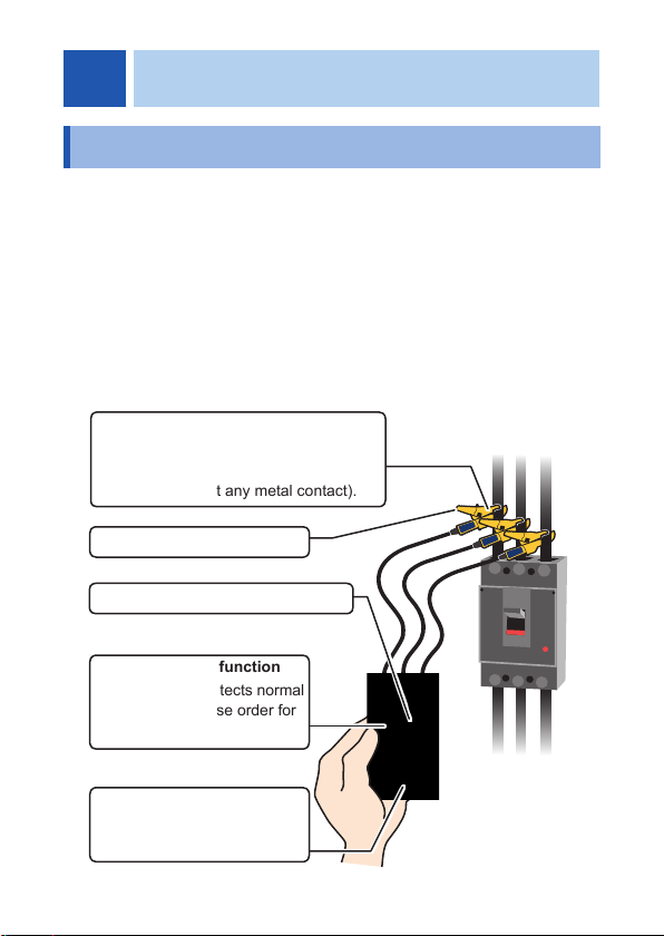
3-phase line voltage measurement
The instrument measures line voltages in
a 3-phase circuit from outside the wires’
insulation (without any metal contact).
Frequency measurement
Missing-phase prediction function
Phase detection function
The instrument detects normal
and reversed phase order for
3-phase circuits.
Hold function
The instrument holds the display
screen in the same state.
11
Page 16
Part Names and Functions
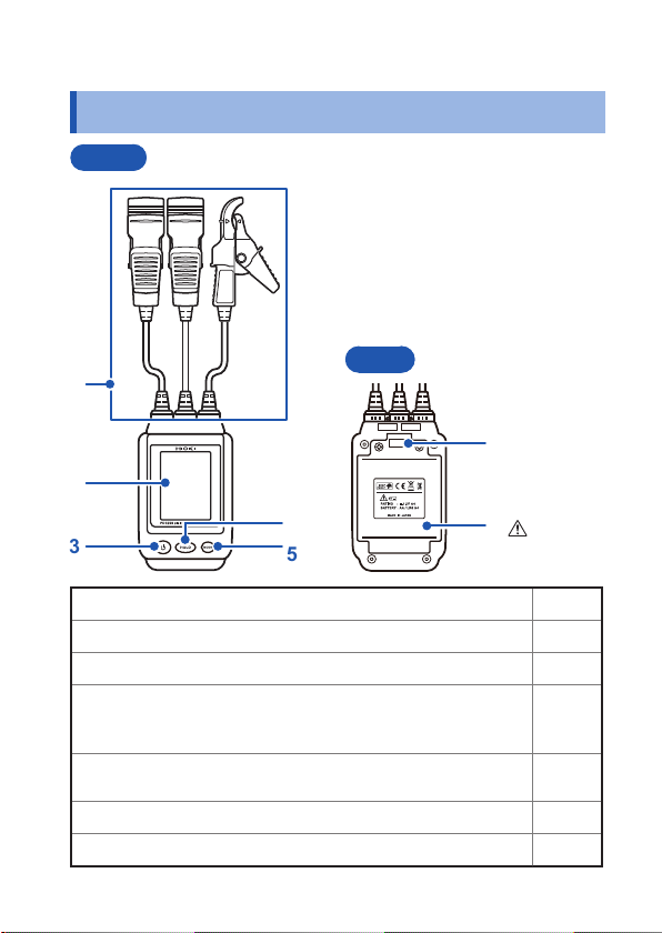
1.2 Part Names and Functions
Front
Rear
1
2
6
4
3
Voltage sensor p. 23
1
Display p. 14
2
POWER p. 22
3
HOLD
4
Allows the user to manually hold the detection results and
measured values being shown on the display.
MODE
5
Switches modes.
Strap slot p. 19
6
Battery cover p. 20
7
5
12
(p. 10)
7
p. 40
–
Page 17
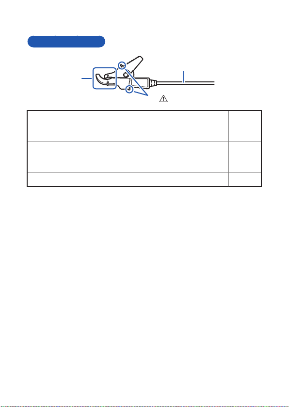
Voltage sensors
1
2
3
4
5
6
7
付録
索引
1
2
3
Part Names and Functions
3
2
(p. 8)
1
Barriers
To avoid electric shock, avoid touching the part of the sensor
beyond these barriers during use.
Clip
Attach the clip to the wire being measured, taking care to
align the position of the measurement target with the marks.
Cable
p. 23
p. 23
–
13
Page 18
Part Names and Functions
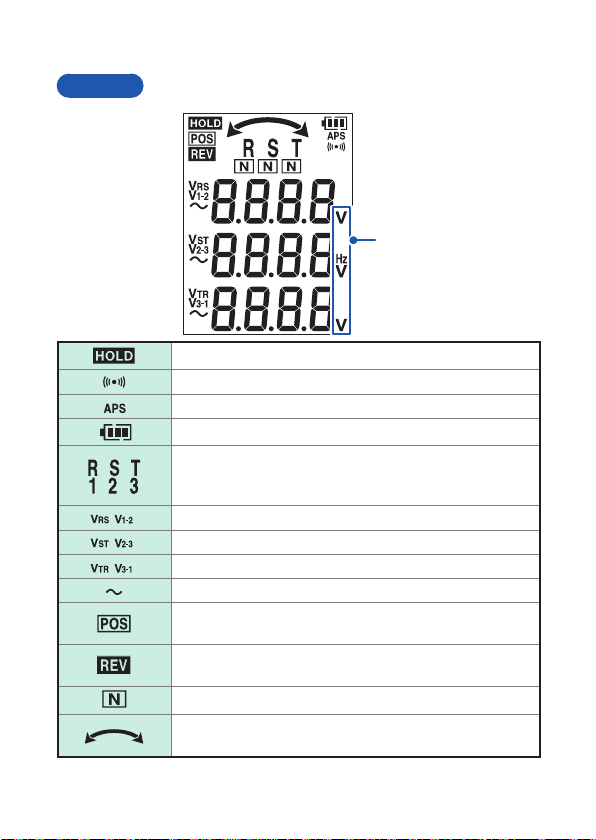
Display
Phase detection results and measured value hold (p. 40)
Phase detection tone enabled (p. 30)
Auto-power-off function enabled (p. 35)
Battery level (p. 15)
Phase display as either R/S/T or 1/2/3 (user-switchable)
( )
( ) Line voltage VRS (V
( ) Line voltage VST (V
( ) Line voltage VTR (V
When a phase is missing, the indicator for that phase will
turn off (missing-phase prediction function)
AC current
Normal (positive) phase sequence order detected when
checking the phase order for a 3-phase circuit
Reversed (negative) phase sequence order detected
when checking the phase order for a 3-phase circuit
Ground phase predicted in a 3-phase/3-wire circuit
Normal or reversed phase order when checking the phase
order for a 3-phase circuit
) (p. 28)
1-2
) (p. 28)
2-3
) (p. 28)
3-1
Units
14
Page 19

1.3 Battery Level
1
2
3
4
5
6
7
付録
索引
Battery level display
There is adequate battery power remaining.
The battery level display provides a rough guideline of how much
continuous operating time remains. When using lithium
battery level indicator does not function properly.
Interruption of power
The graduations in the indicator disappear from the left as the
battery’s power falls.
Soon no battery power will remain. Have new batteries ready.
On continuously
No battery power remains. Replace the batteries with new
batteries immediately.
Flashing
No battery power remains. Replace the batteries with new
batteries immediately. Continued use may cause power to the
instrument to be interrupted. Measurement accuracy cannot
be guaranteed in this state.
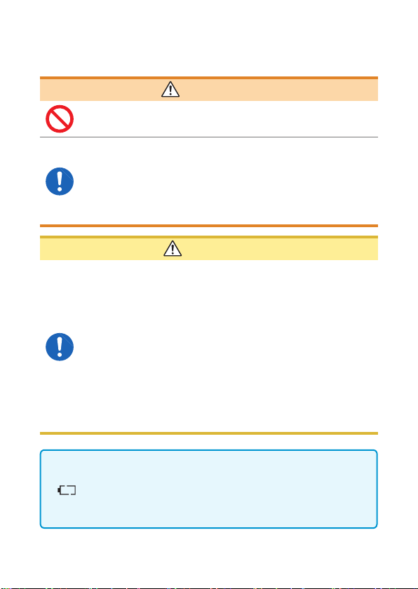
When the indicator shows no remaining battery
power ( flashing), the display will indicate
[bAt t Lo] for 2 seconds, and the instrument will
turn off.
Battery Level
batteries, the
15
Page 20

Preparing for Measurement
1
2
3
4
5
6
7
付録
索引
2
2.1 Measurement Process
Before using the instrument, be sure to read “Operating
Precautions” (p. 7).
Setting up, connecting, and turning on the instrument
Turn on the instrument (p. 20)
Inspect the instrument (p. 21)
Turn on the instrument (p. 22)
Connect voltage sensors (p. 23)
Performing measurement
Measure the circuit (p. 27)
• Measuring line voltages in a 3-phase circuit (p. 28)
• Checking phase order in a 3-phase circuit (phase detection) (p. 30)
• Measuring the frequency (p. 31)
Hold measured values and phase
order detection results (p. 40)
Arrange to use other options as
needed.
Finishing using the instrument
Turn off the instrument (p. 22)
17
Page 21

Attaching Color Spirals and Bundling Cables Together
2.2 Attaching Color Spirals and Bundling Cables Together
Procedure
To aid in differentiating the voltage sensors, attach the
1
included color spirals (red, blue, and yellow) to the voltage
sensor cables.
Bundle the voltage sensor cables together with the included
2
spiral (black).
1
1
2
1
The colors used to identify phases vary by country and region.
Use the included color spirals (red, blue, and yellow) to
differentiate the voltage sensors as necessary.
18
Page 22

Attaching the Magnetic Strap (Optional)
1
2
3
4
5
6
7
付録
索引
2.3 Attaching the Magnetic Strap (Optional)
When the optional Z5020 Magnetic Strap is attached to the
instrument, the magnetic portion can be used to hold the instrument
in place on steel sheet and other magnetic surfaces.
Magnet
Strap slot
19
Page 23

Installing and Replacing Batteries
2.4 Installing and Replacing Batteries
When using the instrument, install four LR6 (AA-size) alkaline
batteries. Verify that sufficient battery strength remains before
measurement. If there is insufficient battery power remaining,
replace the batteries (p. 15).
You will need
• A screwdriver
• LR (AA-size) alkaline batteries × 4
Procedure
Press POWER to turn off the instrument.
1
Untighten the screws that holds the battery cover in place
2
with the screwdriver and remove the cover.
If replacing the batteries, remove all old batteries.
3
Install four new batteries, taking care to orient them properly.
4
Reattach the battery cover and tighten the screw (M3 × 8 mm).
5
Screws
20
Page 24

Inspecting the Instrument
1
2
3
4
5
6
7
付録
索引
2.5 Inspecting the Instrument
Before using the instrument, inspect it for any damage it may have
sustained during storage or shipment and verify its proper operation.
If you find any damage, contact your authorized Hioki distributor or
reseller.
Inspection item Action
The display shows an
error.
Are there any cracks or
other damage?
Is the cables’ insulation
damaged, or is any metal
exposed?
Are the batteries dead? Replace the batteries. (p. 20)
Is the screen displayed
when the instrument is
turned on?
Does the display show
“Pd3259” and a starting
animation when the
instrument is turned on?
Contact your authorized Hioki distributor or
reseller.
The instrument’s insulation may have been
compromised. Avoid using the instrument due to
the risk of electric shock and have it repaired.
If there is any damage, avoid using the
instrument due to the risk of electric shock and
have it repaired.
The batteries may be dead. Replace them with
new batteries and check again.
Check the error codes (p. 51)
Pd3259
Starting animation
21
Page 25

Turning the Instrument On and Off
2.6 Turning the Instrument On and Off
Press POWER to turn the instrument on and off.
22
Page 26

Attaching the Voltage Sensors to the Circuit
1
2
3
4
5
6
7
付録
索引
2.7 Attaching the Voltage Sensors to the Circuit
Proper attachment method
Align the mark on each voltage sensor to the insulated target wire and clip
it securely in place. The sensors can be attached to wires with diameters
ranging from 6 mm to 30 mm.
DANGER
To prevent electric shock, do not touch the clips in
front of the barrier during use.
Example: When measuring a thick insulated wire
Insulated wire
Mark Mark
Insulated wire
Insulated wire
Barriers
Marks
23
Page 27

Attaching the Voltage Sensors to the Circuit
Example: When measuring a thin insulated wire
Insulated wire
Mark Mark
Insulated wire
Barriers
Marks
Insulated wire
24
Page 28

Attaching the Voltage Sensors to the Circuit
1
2
3
4
5
6
7
付録
索引
Improper attachment
If the clips are not attached properly, accurate measurement will be
impossible due to the effects of nearby wires.
The sensor is attached to the
insulated wire by the tip of the clip.
The sensor is attached to the
insulated wire at an angle.
The insulated wire has been
inserted too far into the clip.
The sensor has been clipped
simultaneously to two insulated wires
that are carrying different voltages.
25
Page 29

Setting Up the Instrument in the Measurement Location
2.8 Setting Up the Instrument in the Measurement Location
Attach voltage sensor R (1) to phase R (1), voltage sensor S (2) to phase S (2),
and voltage sensor T (3) to phase T (3).
R S T
(1)(2)(3)
R S T
(1)(2) (3)
TTSS
R
R
(1)(2)(3)
(1)(2)(3)
RRTTSS
(1)(2)(3)
(1)(2)(3)
Measurement while
holding the instrument
Measurement using the Z5004
Magnetic Strap
Line naming conventions
The three phases are known by various conventions.
<Examples>
First phase Second phase Third phase
Attach voltage sensor R (1) to the first phase of the 3-phase circuit, voltage
sensor S (2) to the second phase, and voltage sensor T (3) to the third phase.
R S T
L1 L2 L3
A B C
U V W
26
Page 30

Performing Measurement
1
2
3
4
5
6
7
付録
索引
3
Press
and hold
Line Voltage Measurement
screen (p. 28)
Phase Voltage
Measurement screen
(p. 29)
Phase Detection screen
(p. 30)
Press
and hold
Phase Voltage
Measurement screen
(p. 29 )
Frequency Measurement
screen (p. 31)
Return to Line Voltage
Measurement screen
27
Page 31

Measuring Line Voltages in a 3-phase Circuit
3.1 Measuring Line Voltages in a 3-phase Circuit
Three-phase line voltage measurement
The display will indicate V
When a 3-phase circuit is measured, the three line voltage values
will be shown on the display.
, VST, and VTR (or V
RS
Display the Line Voltage
1
, V
, and V
1-2
2-3
).
3-1
Measurement screen.
(The Line Voltage Measurement
screenisdisplayedfirs whenthe
instrument turns on.)
Check the voltage values.
2
The display will indicate [Lo] if the line
voltage is less than 30.0 V or [ovEr] if the line
voltage exceeds 600.0 V.
28
Page 32

Measuring Line Voltages in a 3-phase Circuit
1
2
3
4
5
6
7
付録
索引
Phase voltage measurement (reference values)
The display will indicate V
a 3-phase circuit is measured, the three phase voltage values will
be shown on the display. However, since the neutral line cannot
be measured, the displayed values indicate each phase’s voltage
relative to the ground using the virtual neutral point (ground) as the
reference.
The displayed phase voltages are reference values whose
accuracy is not guaranteed.
, VS, and VT (or V1, V2, and V3). When
R
Display the Line Voltage
1
Measurement screen.
(The Line Voltage Measurement
screenisdisplayedfirs whenthe
instrument turns on.)
Press and hold MODE.
2
(The Phase Voltage Measurement
screen will be displayed.)
Press and hold
Check the displayed values.
3
The display will indicate [Lo] if the phase
voltage is less than 30.0 V or [ovEr] if the
phase voltage exceeds 400.0 V.
Press MODE.
4
(The Line Voltage Measurement
screen will be displayed.)
29
Page 33

Checking Phase Order in a 3-phase Circuit (Phase Detection Function)
3.2 Checking Phase Order in a 3-phase Circuit (Phase Detection Function)
The instrument displays phase detection results when a 3-phase
circuit is measured. The display’s backlight will light up, and
the instrument will beep to indicate the phase detection results.
However, the tone will not sound if the beep setting is disabled (p. 38).
Display the Phase Detection
1
screen (p. 27).
30
Yellow
Green
Red
Check the Phase Detection screen.
2
Normal phase
The display will indicate , , and
.
The display’s backlight will turn yellow-green,
and the instrument will beep intermittently.
Reversed phase
The display will indicate , , and
.
The display’s backlight will turn red, and
the instrument will beep continuously. (The
instrument will stop beeping automatically after
10 sec. or once the hold function is enabled.)
If unable to detect the phases, the display
will not indicate POS, REV, or an arrow.
Press MODE twice.
3
(The Line Voltage Measurement
screen will be displayed.)
Page 34

Measuring Frequency
1
2
3
4
5
6
7
付録
索引
3.3 Measuring Frequency
The instrument will measure the frequency of the line voltage VRS.
Display the Frequency
1
Measurement screen (p. 27).
Check the measured value.
2
During frequency measurement, only the line voltage VRS
frequency is measured. Specificall , the instrument measures
the differential signal between voltage sensor R (1) and voltage
sensor S (2).
(The frequency of the line voltage
VRS will be displayed.)
The display will indicate [Lo] if the measured
frequency is less than 45.0 Hz or [ovEr] if the
frequency exceeds 66.0 Hz.
Press MODE.
3
(The Line Voltage Measurement
screen will be displayed.)
31
Page 35

Checking Phase Order in a 3-phase Circuit (Phase Detection Function)
32
Page 36

Convenient Uses
1
2
3
4
5
6
7
付録
索引
4
4.1 Power-on Options
Power-on options can be set as described below. (Perform the
indicated operation while the instrument is turned off.)
HOLD
+
MODE
+
Auto-power-on function setting
(p. 35)
Phase display switching function
setting (p. 37)
To power-on screen
Tone setting (p. 38)
To power-on screen
33
Page 37

Power-on Options
HOLD + MODE
Display version information (p. 39)
Display serial number (p. 39)
To power-on screen
+
34
Page 38

Power-on Options
1
2
3
4
5
6
7
付録
索引
Auto power-off function
The instrument provides functionality for limiting battery consumption.
When the auto-power-off function is enabled, the instrument will
automatically turn off once 10 min. has passed since the last key
operation. (It will beep intermittently starting 30 sec. before the
power turns off.)
[APS] icon will be displayed.
The
(Indicating that auto-power-off is enabled)
The auto-power-off function is enabled when the instrument is
turned on normally. The function can also be disabled using poweron options. (p. 36)
35
Page 39

Power-on Options
Disabling the auto-power-off function
Turn on the instrument while holding
down HOLD.
[APS oFF] will be displayed.
The power-on screen will be displayed.
36
The [APS] icon will no longer be displayed.
(Indicating that auto-power-off is disabled)
Page 40

Switching the phase display (phase display
1
2
3
4
5
6
7
付録
索引
switching function)
You can select whether to display phases using the or the
convention.
Phase display
Line voltage display
, , , ,
Turn on the instrument while
1
holding down MODE.
Power-on Options
Press HOLD to select the phase
2
display ([rst]↔[123]).
Press MODE.
3
Press
MODE
4
The phase display switching function setting will take effect the
next time the instrument is turned on.
(After the power-on screen is displayed,
the instrument will display the
Line Voltage Measurement screen.
again.
37
Page 41

Power-on Options
Enabling and disabling the beep function
This section describes how to enable or disable the beeping tones
that the instrument emits during key operation and phase detection.
Turn on the instrument while
1
holding down MODE.
Press MODE.
2
Press HOLD to select whether
3
to enable or disable the beep
function ([on]↔[oFF]).
Press MODE.
4
(After the power-on screen is displayed,
the instrument will display the Line
Voltage Measurement screen.)
The beep function setting will take effect the next time the
instrument is turned on.
38
Page 42

Power-on Options
1
2
3
4
5
6
7
付録
索引
Checking the version and serial number
This section describes how to display version information along with
the instrument’s serial number.
Turn on the instrument while
1
holding down HOLD and MODE
at the same time.
The display will indicate [vEr].
Press MODE.
2
Check the serial number.
3
Example: Serial number “151200001”
Press MODE.
4
(After the power-on screen is displayed,
the instrument will display the Line
Voltage Measurement screen.)
39
Page 43

Holding the Display
4.2 Holding the Display
This section describes how to hold measured values and phase
detection results shown on the display. The hold function can be
used on the Voltage Measurement screen, Phase Detection screen,
and Frequency Measurement screen.
Enabling and disabling the hold function
Press HOLD to select whether to
enable or disable the hold function.
When [HOLD] is not shown (during
normal operation):
The hold function is disabled.
When [HOLD] is shown:
The hold function is enabled.
(Measured values and detection
results will be held.)
When normal phase is detected and when the instrument is
unable to detect the phase, the yellow-green backlight will turn
on. When reversed phase is detected, the red backlight will turn
on.
40
Page 44

Turning On the Backlight
1
2
3
4
5
6
7
付録
索引
4.3 Turning On the Backlight
This section describes how to turn on the backlight. The backlight
makes it possible to view the display clearly in dim locations where
the LCD would otherwise be difficult to see
Enabling and disabling the backlight
Press and hold
(To select whether to enable or disable
the backlight.)
HOLD.
Ordinarily the yellow-green backlight
turns on. The red backlight turns on only
when reversed phase is detected.
The backlight automatically turns off 30
sec. after turning on, regardless of the hold
function or screen transitions. However,
when phase detection results are being
displayed on the Phase Detection screen,
the backlight color will change to reflect the
phase detection results after 30 sec.
41
Page 45

Displaying the Predicted State for a 3-phase Circuit
4.4 Displaying the Predicted State for a 3-phase Circuit
When measuring a 3-phase circuit with Δ wiring in which one phase
is grounded, the PD3259 can automatically predict the grounded
phase. In addition, the instrument can predict if one line of the
3-phase circuit is missing. The results are shown using icons on the
display (These functions are only used in Japan.)
3-phase/3-wire
Proper identification of the ground phase or missing phase is not
guaranteed. Results may be inaccurate if the circuit incorporates
complex wiring or if the distance from the point of measurement
to the break in the wire meets certain criteria.
Ground phase prediction
If the S phase is grounded, the display
will indicate underneath . Similarly,
if the R phase is grounded, the display
will indicate
the T phase is grounded, the display
will indicate underneath . (Similar
displays are used if 1/2/3 numbering is
used for the phase display.)
Missing phase prediction
If the instrument predicts that one wire of
the 3-phase circuit is missing, the icon
for the phase predicted to be missing
( or ) will not be displayed.
underneath , and if
42
Page 46

Specification
1
2
3
4
5
6
7
付録
索引
5
5.1 GeneralSpecification
Operating environment Indoors, Pollution Degree 2, altitude up to 2000
Operating temperature
and humidity
Storage temperature
and humidity
Dust-proof, water-proof
Standards Safety: EN61010
Dielectric strength 7.4 kV AC (sensed current: 1 mA)
Power supply LR6 (AA-size) alkaline battery × 4
Continuous operating
time
Dimensions Instrument: Approx. 84W × 146H × 46D mm
Cable length Approx. 0.5 m
Mass Approx. 590 g (20.8 oz.) (including batteries)
Product warranty period
Accessories See p. 1.
m (6562 ft.)
Temperature: -25°C to 65°C (-13°F to 149°F)
Humidity: 80% RH or less at less than 50°C
(no condensation)
50% RH or less at 50°C to 65°C (no
condensation)
-25°C to 65°C (-13°F to 149°F), 80% RH or less
(no condensation)
Instrument (excluding voltage sensor): IP54 (EN
60529)
EMC: EN61326 Class A
Between voltage sensor opening and instrument
enclosure
Rated supply voltage: 1.5 V DC × 4
Maximum rated power: 3 VA
When using LR6 (AA-size) alkaline battery × 4
(reference value at 23°C)
Approx. 5 hr. (with display backlight off and
instrument in standby state)
(3.31”W × 5.75”H × 1.81”D)
3 years
43
Page 47

Input Specifications and Measurement Specificatio
Options See p. 2.
5.2 InputSpecification and
MeasurementSpecification
Basicspecification
Measurement
parameters
Measurement targets Insulated wires*, metal parts*
Measurable conductor
diameter
Voltage detection
method
Voltage sensor rated
voltage
Voltage measurement
method
Measurement display 4-digit 7-segment LCD × 3
Response time 3 sec. or less
Display update rate 500 ±10 ms
Maximum rated input to
ground voltage
3-phase AC voltage (line voltage, voltage
relative to ground), frequency
*Not compatible with shielded wires.
3-phase 90.0 V AC to 520.0 V AC (45 Hz to 66
Hz)
Outer diameter: φ6 mm to 30 mm
Coupled capacitance cancellation method
400 V AC relative to ground per voltage sensor
circuit
Digital sampling, true RMS method
600 V AC (CAT IV)
Anticipated transient overvoltage: 8000 V
44
Page 48

Accuracyspecification
1
2
3
4
5
6
7
付録
索引
Conditions of
guaranteed accuracy
Line voltage
measurement accuracy
Frequency
measurement accuracy
Effects of external
magneticfield
Effects of nearby wires Add ±4.0 V to measured voltage values.
Temperaturecoefficien
Effects of humidity Add ±4.0 V to measured voltage values.
Line voltage phase
difference shift
Guaranteed accuracy period: 1 year
Guaranteed accuracy period from adjustment
made by Hioki: 1 year
Temperature and humidity for guaranteed
accuracy: 23°C ±5°C (73°F ±9°F), 80% RH or
less
Warm-up time: Max. 10 sec.
Number of voltage sensor clip open/close
cycles: 8,000 or less
±2.0% rdg. ±8 dgt. (1-year accuracy)
±3.0% rdg. ±8 dgt. (3-year accuracy; reference
value)
±0.5% rdg. ±1 dgt.
Within ±6.0 V for 400 A/m AC (50 Hz/60 Hz) fiel
(Value describes effect when an adjacent wire
with a potential difference of 400 V AC is in
contact with the voltage sensor’s clip.)
±0.4 V/°C (at other than 23°C ±5°C)
(When measuring insulated wires at a humidity
level of 70% RH to 80% RH)
Equivalent to ±2.6°
5.3 FunctionalSpecification
Phase detection
function
Normal (positive) phase, reversed (negative)
phase (3-phase/3-wire, 3-phase/4-wire)
45
Page 49

Other Specification
Missing phase
prediction function
Predicts missing phase.
5.4 OtherSpecification
Hold function Displayed values are held when the HOLD key
Display backlight function The display is illuminated by a yellow-green
Beep function Key tone: Single tone
Auto-power-off function The instrument automatically turns off
Low battery warning Displays the remaining battery strength (in 4
Drop-proof The instrument can withstand being dropped
is pressed.
backlight when the hold function is enabled.
However, the backlight will turn red when
reversed phase is detected.
Pressing and holding the HOLD key activates
the backlight.
Backlight time: Max. 30 sec. ±2 sec.
When normal phase is detected by phase
detection function: Intermittent tone
When reversed phase is detected by phase
detection function: Continuous tone (max. 10
sec. ±1 sec.)
(The beep function can be muted.)
approximately 10 min. after the last key
operation.
(The auto-power-off function can be disabled.)
levels)
onto a concrete surface from a height of 1 m.
46
Page 50

Maintenance and Service
1
2
3
4
5
6
7
付録
索引
6
6.1 Repair, Inspection, and Cleaning
IMPORTANT
If the instrument is dirty, wipe it gently with a soft cloth that has
been moistened with a small amount of water or neutral detergent.
Disposal
When disposing of the instrument, be sure to adhere to all
applicable local regulations.
Calibration
The interval at which the instrument must be calibrated varies with
the manner and environment in which it is used. It is recommended
to determine the appropriate calibration interval based on the
manner and environment in which you intend to use the instrument
and then to request Hioki to calibrate it on a regular basis
accordingly.
47
Page 51

Troubleshooting
6.2 Troubleshooting
If you encounter an issue with the instrument and believe it may be
malfunctioning, review the information provided in “Before having
the instrument repaired” below. If unable to resolve the issue,
contact your authorized Hioki distributor or reseller.
Before having the instrument repaired
Issue What to check Solution
The screen
does not show
anything when
the instrument is
turned on.
Measured values
are not displayed.
Have batteries been
properly installed in
the instrument?
Are the batteries
dead?
Have the voltage
sensors been properly
attached to the
measurement targets
(wires)?
Have multiple
voltage sensors been
attached to the same
measurement target
(wire)?
Check the type of
battery in use and
the orientation in
which they have
been installed.
Replace the spent
batteries with new
batteries.
Check how the
voltage sensors
have been
attached to the
wires.
Attach each
voltage sensor to
only one wire. p. 23
48
More
information
p. 20
p. 20
p. 23
Page 52

Troubleshooting
1
2
3
4
5
6
7
付録
索引
Issue What to check Solution
Measured values
fail to stabilize.
Is the measurement
target’s frequency
50 Hz or 60 Hz?
The instrument does
not support 400 Hz
frequency as a line
frequency.
The instrument
is designed
exclusively for use
with 50 Hz and
60 Hz circuits.
(The accuracy
guarantee only
applies to the
frequency range
of 45 Hz to 66 Hz.)
The instrument
cannot be used to
measure 400 Hz
circuits accurately.
More
information
–
49
Page 53

Troubleshooting
Issue What to check Solution
Phase detection
results fail to
stabilize.
Is the measurement
target’s frequency
50 Hz or 60 Hz? The
instrument does not
support the frequency
of 400 Hz.
Have the voltage
sensors been properly
attached to the
measurement targets
(wires)?
Have multiple
voltage sensors been
attached to the same
measurement target
(wire)?
The instrument
is designed
exclusively for use
with 50 Hz and
60 Hz circuits.
(The accuracy
guarantee only
applies to the
frequency range
of 45 Hz to 66 Hz.)
The instrument
cannot be used to
measure 400 Hz
circuits accurately.
Check how the
voltage sensors
have been
attached to the
wires.
Attach each
voltage sensor to
only one wire. p. 23
More
information
–
p. 23
50
Page 54

Error codes
1
2
3
4
5
6
7
付録
索引
Troubleshooting
Error
display
Err 001 ROM error program Take the following action if the
Err 002 ROM error adjustment
Err 003 ADC error
Description Solution
display indicates an error:
data
Hardware failure
Replace the batteries with new
batteries (p. 20). If this fails to
resolve the issue, the instrument
needs to be repaired.
51
Page 55

Appx. 1 About 3-phase Circuits
1
2
3
4
5
7
付録
索引
3-phase 400 V lines
Appendix
Displayed voltages
1
240 V*
1
240 V*
The 400 V lines depicted in the figure have a line voltage of
240 V*
1
Ground
415 V*
415 V*
2
2
*1: Voltage relative to
2
415 V*
*2: Line voltage
ground
(For 3-phase/4-wire
circuits, equivalent
to phase voltage)
415 V yet have a voltage relative to ground of approximately
240 V. It is possible to measure this circuit using a
measuring instrument rated for an input-to-ground voltage of
300 V.
The PD3259’s input-to-ground voltage rating of 400 V
enables it to be safely be used to measure lines with a line
voltage of 415 V.
Appx.1
Page 56

About the Instrument’s Voltage Sensors
If
IfCV= 2
π
Appx. 2 About the Instrument’s Voltage
Sensors
Each of the instrument’s voltage sensors incorporates an internal
electrode (metal plate). When the voltage sensor is clipped around
the measurement target (wire), the minuscule current I flows due
to capacitive coupling between the measurement target and the
voltage sensor’s internal electrode.
π
CV= 2
(1)
: Frequency of measurement target [Hz]
: Capacitance between measurement target and voltage sensor’s
internal electrode [F]
: Voltage (AC) between the measurement target and the voltage
sensor’s internal electrode [V]
Measurement target (wire)
V
1
V
2
Voltage sensor’s
internal electrode
Voltage
generation
circuit
Appx.2
Page 57

About the Instrument’s Voltage Sensors
1
2
3
4
5
7
付録
索引
V
is controlled so that I = 0.
2
V
=
V
Since
1
when I = 0,
2
V
is measured to obtain
2
V
.
1
Based on equation (1), I = 0 when V = 0 (when the measurement
target and the voltage sensor’s internal electrode are at the same
potential).
The instrument’s voltage sensors detect the minuscule current I, and
the voltage of the voltage sensor’s internal electrode is controlled
so that I = 0. The same voltage (
voltage (
V
) is generated internally by the sensor.
1
V
) as the measurement target’s
2
The instrument implements a voltage measurement method that does not
require contact with exposed metal surfaces on the measurement
target by measuring the voltage generated internally by the voltage
sensor (
V
) when
2
V
=
V
. (This method is known as the coupled
1
2
capacitance cancellation method.)
Appx.3
Page 58

Index
A
APS ...................................... 14
Auto-power-off function .. 14, 35
Disabling auto-power-off
function ............................. 36
B
Barriers ..................... 12, 13, 23
Battery level display.............. 15
Beeping tones....................... 38
C
Cables .................................... 9
Clip ....................................... 13
Coupled capacitance
cancellation method....... Appx.3
D
Display .................................. 14
H
HOLD.................................... 14
Hold function......................... 40
I
Insulated wire ....................... 44
Interruption of power............. 15
L
LR6 (AA-size) alkaline
batteries .................................. 1
M
Magnetic strap .................. 2, 19
Measuring frequency ............ 31
Measuring line voltages in a
3-phase circuit ...................... 28
N
Normal (positive) phase........ 30
O
Options ................................... 2
P
Phase detection .................... 14
Phase display ................. 14, 37
Phase voltage ....................... 29
POS ...................................... 14
POWER ................................ 22
R
REV ...................................... 14
Reversed (negative) phase .. 30
S
Spiral tubes............................. 1
Line voltage .......................... 14
Test Equipment Depot - 800.517.8431 - 99 Washington Street Melrose, MA 02176
TestEquipmentDepot.com
Ind.1
 Loading...