

Hioki MR8904 Instruction Manual

MR8904
CAN UNIT
Instruction Manual
Sept. 2018 Revised edition 3
MR8904A981-03 18-09H
EN


Contents
Introduction ..................................................1
i
Contents
Confirming Package Contents....................1
Safety Notes..................................................2
Usage Notes..................................................4
Chapter 1 Product Overview 7
1.1 Features .............................................. 7
Chapter 2 Names and
Functions of Parts 9
Chapter 3 Connections 11
3.1 Installing and Removing the
MR8904 into and from a Memory
HiCorder ............................................ 11
3.2 Connecting the Unit to the
Measurement Target ........................12
3.3 Connecting the Unit to a PC ...........14
Chapter 5 Settings 23
5.1 Launching and Exiting the
Software ............................................23
• To connect a Memory HiCorder after
launching the MR8904 CAN Editor ............... 24
5.2 Screen Types ....................................25
5.3 Creating a CAN Definition Data File 26
• How to count the bit position .........................28
• Calculating the start bit (data start position).. 28
• Byte order ................... ...................................29
• To read a saved CAN definition data file .......29
• To load an existing CANdb file ......................30
• To set a password when opening a saved
CAN definition data file.................................. 30
• To delete, edit, or duplicate registered CAN
definition data ................................................30
5.4 Creating Condition Settings Files ...34
Loading a CAN definition data file ............ 34
• To edit the [CAN Definition Data List] ............35
Registering CAN definitions
(creating an MR8904 register list) ............ 36
Installing the USB driver ...........................14
Connecting the Memory HiCorder and PC 17
Uninstalling the USB Driver ......................19
Chapter 4 Preparing the
MR8904 CAN Editor 21
4.1 Operating Environment ...................21
4.2 Installing the MR8904 CAN Editor ..21
4.3 Uninstalling the MR8904 CAN
Editor .................................................22
MR8904A981-03
• To edit the [MR8904 Register List]................ 37
Setting CAN communications conditions . 38
Allocating channels (Creating MR8904
analog/logic assign lists) .......................... 40
• What is an ID trigger? ....................................41
• Deleting data from an assign list ...................41
Configuring transmission
(creating an MR8904 Send list) ............... 42
• To edit the [MR8904 Send List] .....................42
Saving a list
(saving a condition settings file) ............... 44
• To load a previously saved condition settings
file ..................................................................44
5.5 Printing a Condition Settings File ...45

ii
Contents
5.6 Sending and Receiving Condition
Settings .............................................46
Sending condition settings ....................... 46
Receiving condition settings .................... 47
5.7 Window Menu Commands ...............48
Launch window....................... ... ... .... ....... 48
CAN Definition Data File Settings window 49
Condition Settings window ....................... 50
Chapter 6 Configuring
Settings with the Memory
Chapter 8 Maintenance and
Service 63
8.1 Troubleshooting .............................. 63
8.2 Cleaning ............................................64
HiCorder 51
6.1 Checking and Editing Settings .......51
6.2 Checking Analog Channel
Allocation ..........................................52
6.3 Checking Logic Channel
Allocation ..........................................54
6.4 Setting the Transmission Timing ....55
Chapter 7 Specifications 57
7.1 Model MR8904 Specifications .........57
7.2 Model 9713-01 CAN Cable
Specifications (Terminates in Bare
Wires on One End) ...........................58
7.3 Model 9713-02 CAN Cable
Specifications (for Onboard Vehicle
Connectors) ......................................59
7.4 MR8904 CAN Editor General
Specifications ...................................60
Introduction
Introduction
Thank you for purchasing the Hioki Model MR8904 CAN Unit. To obtain maximum performance from the
MR8904, please read this manual first, and keep it handy for future reference.
Registered trademarks
• Windows is a registered trademark of Microsoft Corporation in the United States and/or
othe
r countries.
• CANdb is a registered trademark of
Vector Infomatik in Germany.
Confirming Package Contents
1
When you receive the MR8904, inspect it carefully
particular, check the accessories and connectors. If damage is evident, or if it fails to operate according to
the specifications, contact your dealer or Hioki representative.
to ensure that no damage occurred during shipping. In
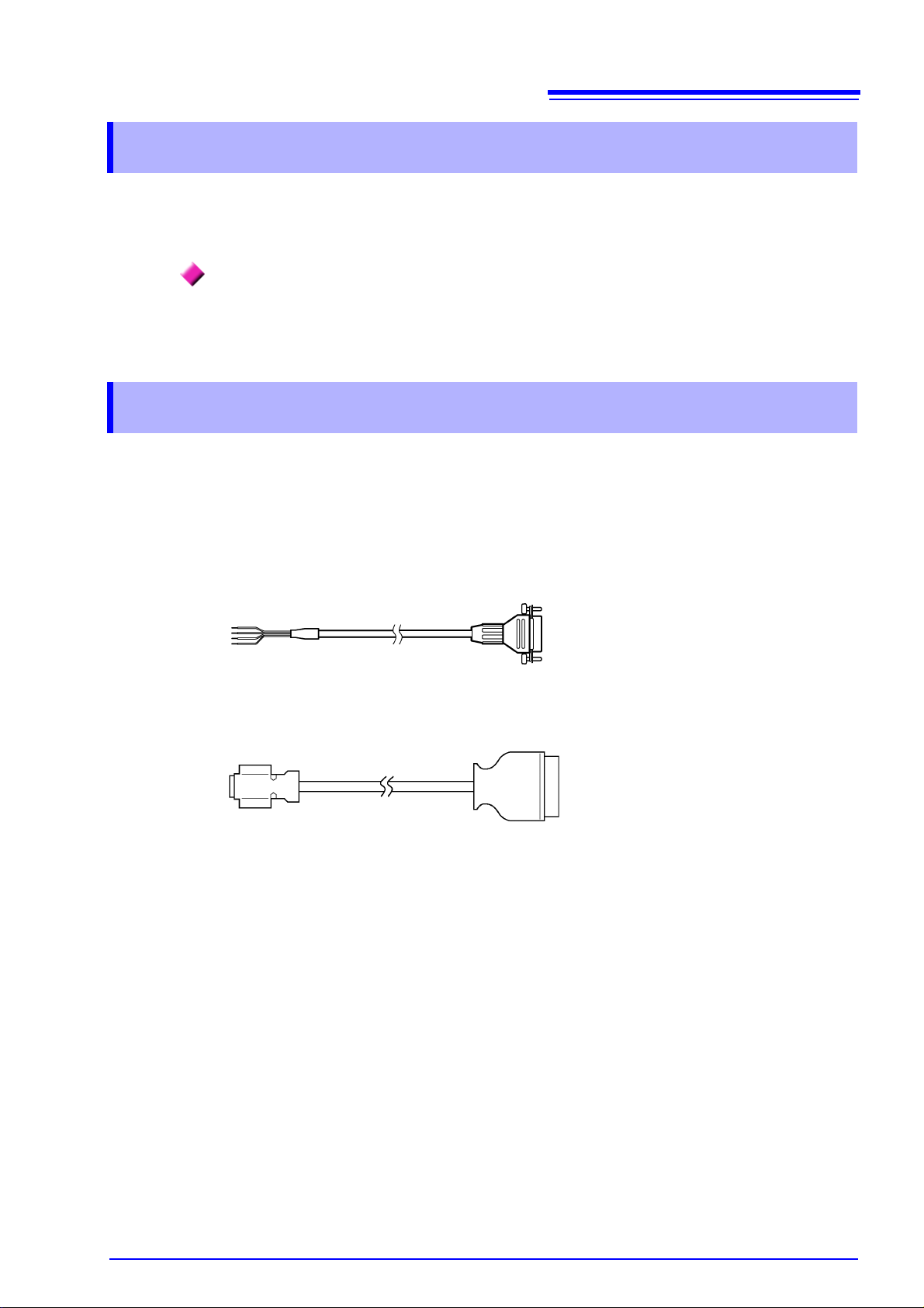
Options
Model 9713-01 CAN Cable
(No connector on one end; approx. 2 m)
Model 9713-02 CAN Cable
(For vehicle equipment connectors; approx. 2 m; made to order; check specifications and availability)
2
Safety Notes
Safety Notes
This manual contains information and warnings essential for safe operation of the MR8904 and for main-
taining it in safe operating condition. Before using it, be sure to carefully read the following safety precautions.
This MR8904 is designed to comply with IEC 61010 Safety Standards, and has been
thoroughly tested for safety prior to shipment. However, mishandling during use
could result in injury or death, as well as damage to the MR8904. Using the MR89 04 in
a way not described in this manual may negate the provided safety feat ures.
Be certain that you unde rstand the instructions and precautions in the manua l bef ore
use. We disclaim any responsibility for accidents or injuries not resulting directly
from MR8904 defects.
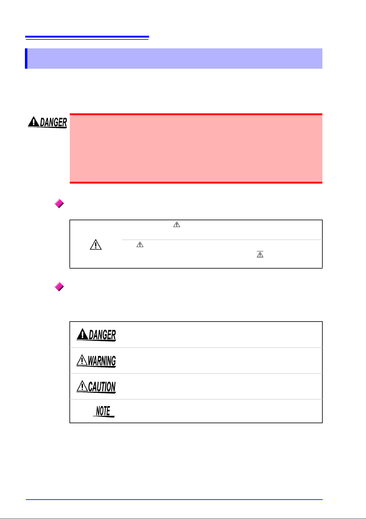
Safety Symbols
In the manual, the symbol indicates particularly important information that
the user should read before using the MR8904.
The symbol printed on the MR8904 indicates that the user should refer to a
corresponding topic in the manual (marked with the symbol) before using
the relevant function.
Hazard Labeling
The following symbols in this manual indicate the relative importance of cautions and warnings.
Indicates that incorrect operation presents an extreme hazard that could result in
serious injury or death to the user.
Indicates that incorrect operation presents a significant hazard that could result
in serious injury or death to the user.
Indicates that incorrect operation presents a po
damage to the MR8904.
ssibility of injury to the user or
Indicates advisory items related to performance or correct operation of the
MR8904.

3
Safety Notes
Notation
• Unless otherwise specified, “Windows” represents Windows XP, Windows Vista, Windows 7,
or Windows 8.
• Menus, commands, dialogs, buttons in a dialog
keys are indicated in brackets.
(p. ) Indicates the location of reference information.
Indicates quick references for operation and remedies for troubleshooting.
Mouse action terminology
, and other names on the screen and the
Click
Right-click
Double click
Drag
Activate
Press and quickly release the left button of the mouse.
Press and quickly release the right button of the mouse.
Quickly click the left button of the mouse twice.
While holding down the left button of the mouse, move the mouse and then
release the left button to deposit the chosen item in the desired position.
Click on a window on the screen to activate that window.
4
Blank panel
Usage Notes
Usage Notes
Follow these precautions to ensure safe ope ra tio n an d to obtain the full benefits of the various functions.
Operating temperature and humidity: As per Memory HiCorder specifications
Storing temperature and humidity:
Temperature: -20C to 60C (- 4 to 140°F)
Humidity : -20 C to 40C (-4 to 104°F) 80%RH or less (non-condensating)
40C to 45C (104 to 113°F) 60%RH or less (non-condensating)
45C to 60C (113 to 140°F) 50%RH or less (non-condensating)
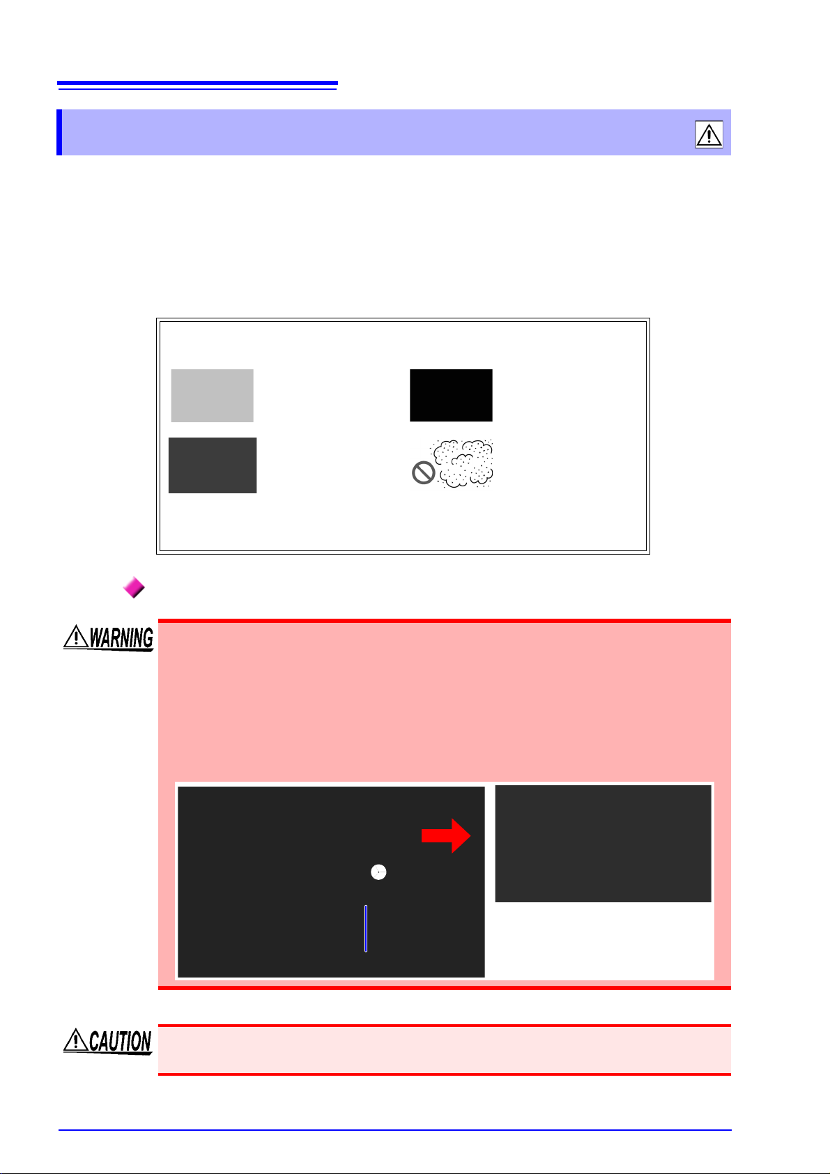
Avoid the following locations that could cause an accident or damage to
the instrument.
Exposed to direct sunlight
Exposed to high tem-
perature
Exposed to water, oil,
o
ther chemicals, or
solvents
Exposed to high humidity or condensation
In the presence of corrosive or explosive gases
Exposed to high levels
o
f particulate dust
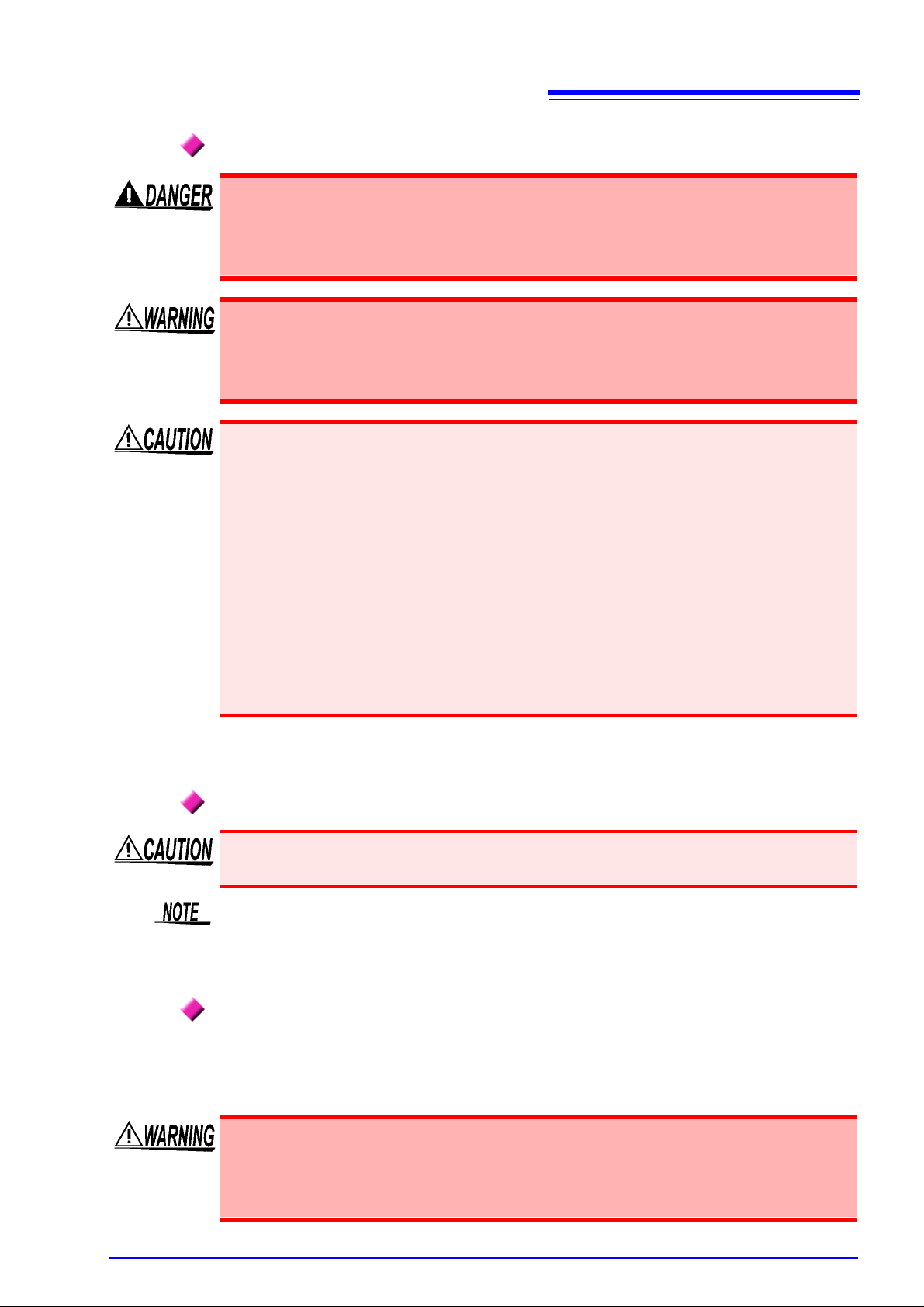
When Installing and Removing the MR8904 into and from the Memory
HiCorder
• To avoid electric shock accident, before removing or replacing an MR8904, confirm
that the instrument is turned off and that the power cord and connection cables are
disconnected. The mounting screws must be firmly tightened or the MR8904 and
the Memory HiCorder may not perform to specifications, or may even fail.
• To avoid the danger of electric shock, never operate the Memory HiCorder with an
input
module removed. To use the Memory HiCorder after removing an input mod-
ule, install a blank panel over the opening of the removed module.
Measurements made without a blank panel installed may fail to meet specifications
because of temperature instability within the input modules.
See: "3.1 Installing and Removing the MR8904 into and from a Memory HiCorder" (p.11)
Usage Notes
When Connecting the MR8904 and the Object under Measurement
This device is designed to collect messages being transferred on the CAN bus and to
send messages to the CAN bus. Do not connect it to anything other than a CAN bus.
In addition to damaging the Memory HiCorder, CAN Unit, and measurement target,
doing so may cause bodily injury.
Use of the CAN Unit may affect the operation of the CAN bus as well as systems connected to the CAN bus. The resulting operation may cause bodily injury or property
damage. V
ated systems before use.
• When connecting the MR8904 to a CAN bus, exercise care not to connect the power supply and ground lines backwards. Doing so may damage the MR8904 and measurement
ta
rget.
• When measuring low-speed CAN or single-wire CAN bus
ground and measurement cable ground lines are not isolated. Wire the system so that no
potential difference occurs between the ground lines. Failure to do so may damage the
Memory HiCorder, CAN Unit, and measurement target.
erify how CAN Unit use, both proper and inadvertent, may affect associ-
es, the Memory HiCorder
5
• When connecting the CAN unit to a low-speed
be supplied form an external source. Since the Memory HiCorder’s ground and measurement cable ground lines are not isolated in this con
from a circuit with the same ground. Failure to do so may damage the Memory HiCorder,
CAN Unit, and measurement target.
CAN or single-wire CAN bus, power must
figuration, be sure to provide power
See: "3.2 Connecting the Unit to the Measurement Target" (p.12)
Transport and Handling
To avoid damage to the MR8904, protect it from physical shock when transporting and handling. Be especially careful to avoid physical shock from dropping.
This device may cause interference if used in residential areas. Such use must be avoided
unless the user takes special measures to reduce electromagnetic emissions to prevent inter
ference to the reception of rad
io and television broadcasts.
Before Use
Before using the MR8904 for the first time, verify that it ope
damage occurred during storage or shipping. If you find any damage, contact your dealer or
Hioki representative.
rates normally to ensure that no
-
Before using the MR8904, make sure that the insulation on the cables is undamaged
and that no bare conductors are improperly exposed. Using the product in such conditions could cause an electric shock, so contact your dealer or Hioki representative
for rep
air.

6
Usage Notes

1.1 Features
Product Overview Chapter 1
The MR8904 is an input module for Memory HiCorder that captures necessary data from CAN bus signaling and transfers analog or logic signals to a Memory HiCorder as waveform data.
• When you connect the Memory HiCorder to a PC with a USB cable, you can configure the MR8904
from the PC with the MR8904 CAN Editor application (the USB cable and application are included with
the Memory HiCorder).
• Up to 200 CAN definitions can be registered.
The MR8904 is a Memory HiCorder option. It should only be used when installed in a Memory HiCorder.
Supported models: MR8875
1.1 Features
7
Extensive number of output channels
The MR8904 provides an extensive
and a 16-bit logic channel.
number of output channels, including 15 analog channels
Two independent input ports
The device’s independent CAN1 and CAN2 ports a
works with different CAN bus types or baud rates.
llow it to be connected to different net-
Support for three types of CAN bus
A single MR8904 provides support for three type
CAN, and single-wire CAN.
s of CAN bus: high-speed CAN, low-speed
Automatic baud rate configuration
The MR8904 monitors the CAN bus and automatically con
eliminating the need to make troublesome settings (12 baud rates are supported: 10k, 20k,
33.3k, 50k, 62.5k, 83.3k, 100k, 125k, 250k, 500k, 800k, and 1 Mbps). The baud rate can also
be set manually.
figures the baud rate accordingly,
PC-accessible advanced settings
Advanced settings concerning data captured from
MR8904 CAN Editor, an application featuring exceptional usability.
the CAN bus can be configured with the
Real-time waveform observation
The MR8904 converts CAN signals into analog and logic
be observed as waveforms on the Memory HiCorder.
data in real time, allowing signals to

8
1.1 Features
Support for mixed recording
Used in combination with other Memory HiCorder optional input modules, the MR8904 can be
used to implement mixed recording of sensor data and control signals on a CAN bus as well
as signals that cannot be acquired on a CAN bus.
Ability to send data to the CAN bus
The MR8904 can send ACK responses to CAN messages as well as CAN messages themselves, allowing it to be used in simple
simulations.
Use of CANdb files
The MR8904 can use Vector’s CAN communications datab
CANdb file, there is no need to create new CAN definitions.
ase files. If you already have a
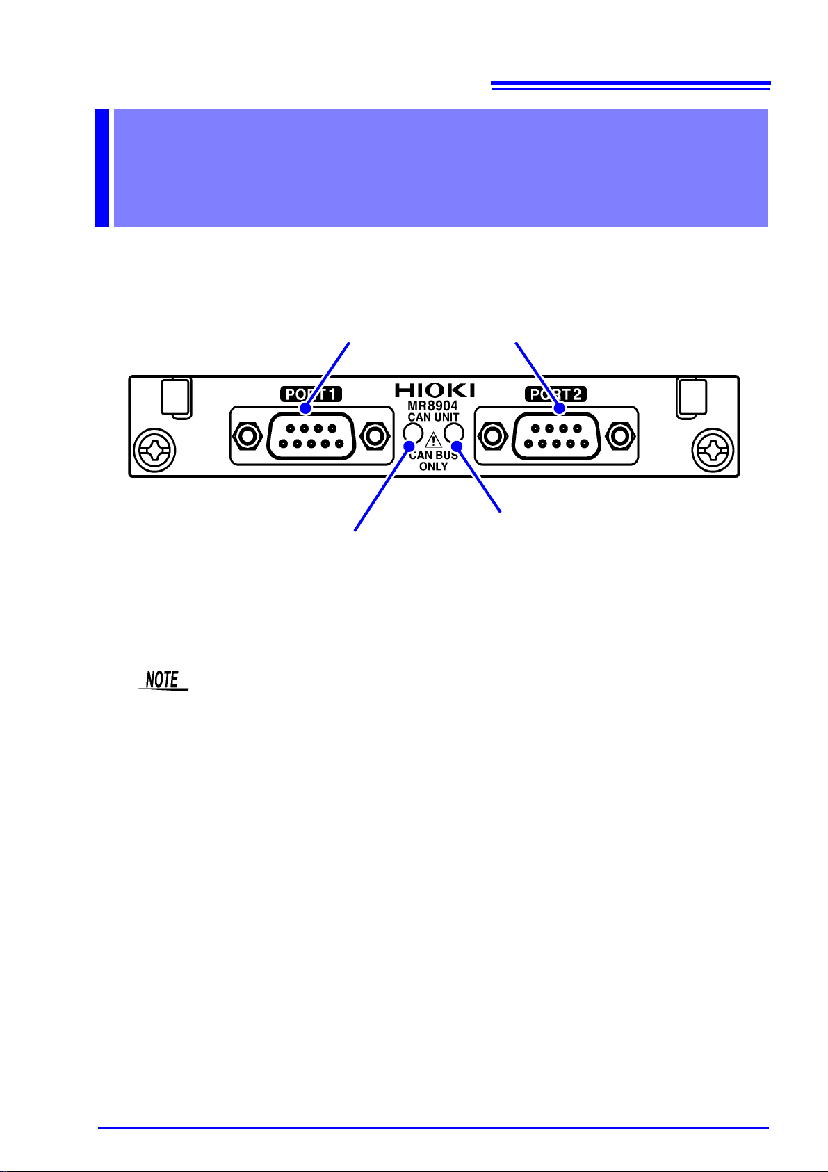
Names and
CAN input port 1 (left) and 2 (right)
CAN signal input terminals. CAN1 and CAN2 are independent and can be
connected to different networks.
CAN LED1
• Turns green when a CAN message allocated to the port 1 output channel is input.
• Turns red when port 1 exp eri ences a n er ror.
CAN LED2
• Turns green when a CAN messag e allocate d
to the port 2 output channel is input.
• Turns red when port 2 experie nces an error.
Functions of PartsChapter 2
9
When an error is encountered, the port in question will enter ACK OFF mode, making it
unable to send messages or issue ACK responses.
The error state will return to normal after measurement completes.
When a port enters an error state, verify that the wiring and CAN communications conditions are correct.

10
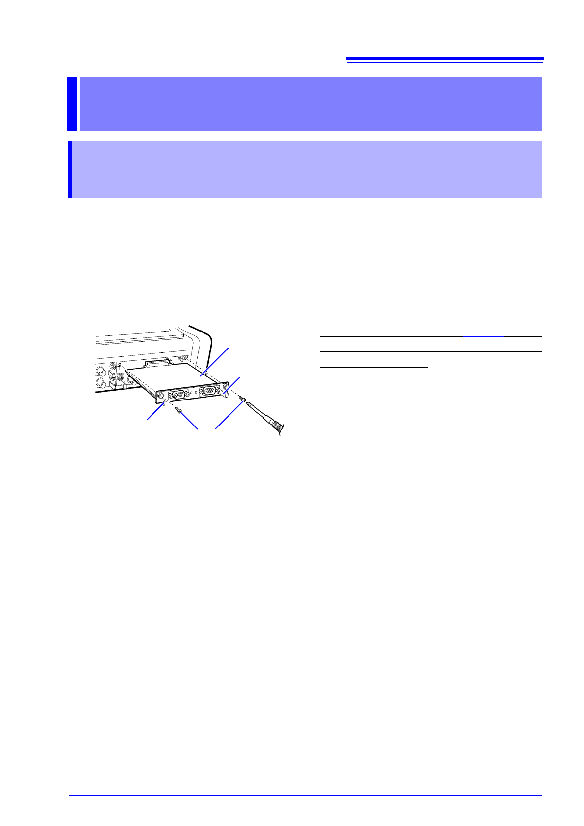
3.1 Installing and Removing the MR8904 into and from a Memory HiCorder
MR8904
Mounting
screws
1 Turn the Memory HiCorder POWER switch
off and unplug the AC adapter and any
measurement cords.
2 With attention to the orientation of the
MR8904, insert it firmly all the way in.
3 Using the Phillips screwdriver, tighten the
two MR8904 mounting screws.
To remove the MR8904, turn off the Memory
HiCorder, disconnect any cords that are connected
to the MR8904, and remove the device by reversing the procedure described above.
Grip
Grip
Connections Chapter 3
3.1 Installing and Removing the MR8904 into
and from a Memory HiCorder
Before connecting the device, be sure to read "When Installing and Removing the MR8904 into and from
the Memory HiCorder" (p.4), which describes how to install a newly purchased MR8904 into a Memory
HiCorder and how to switch between it and other input modules.
(Example: MR8875)
Required
items: Phillips head screwdriver (No.1)
11
12
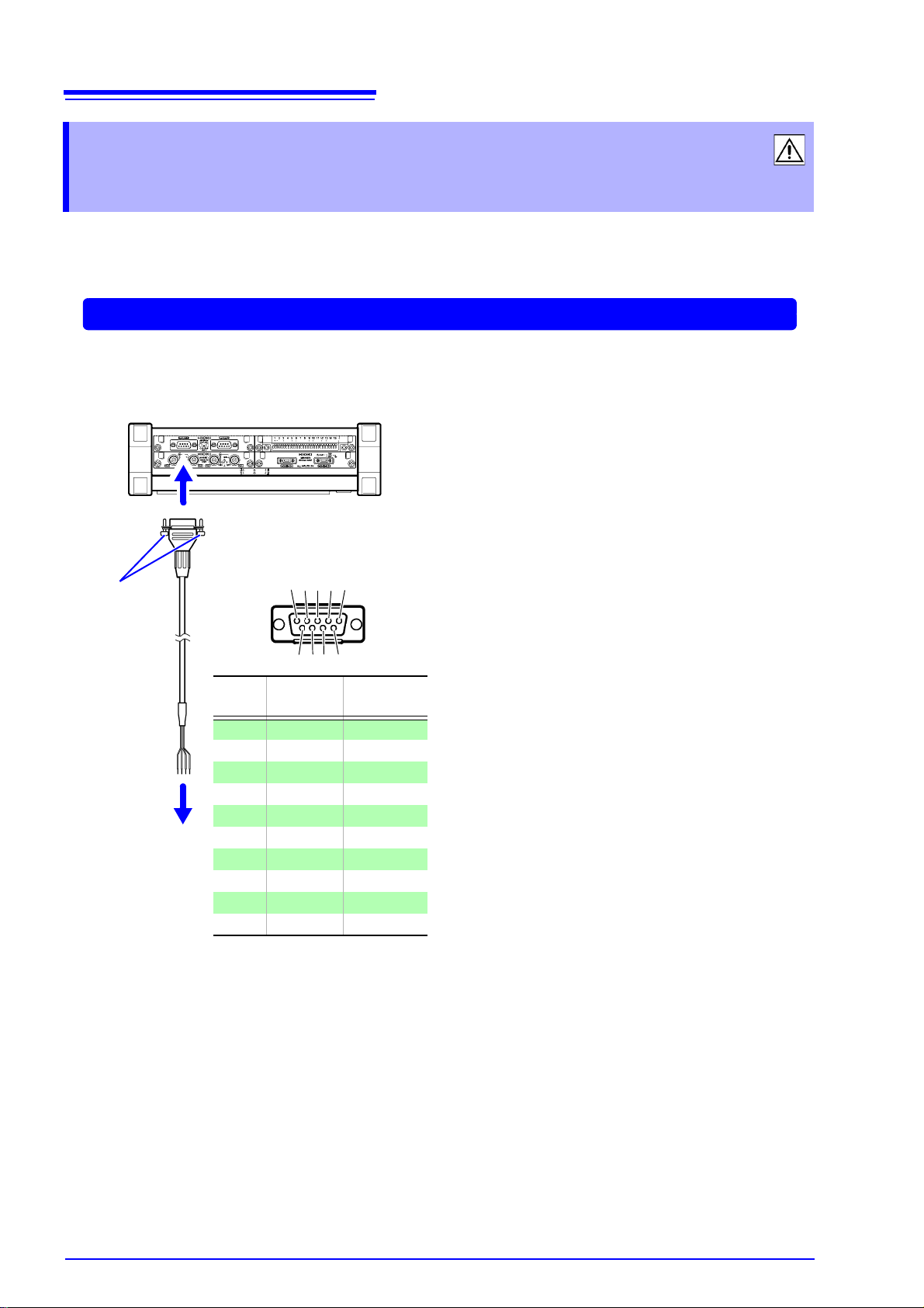
Example: Connecting the unit with the 9713-01
Wire
color
Pin no.
Receive
signal name
- 1 NC
Green 2 CAN_L
Black 3 CAN_GND
- 4 NC
- 5 NC
- 6 NC
Red 7 CAN_H
- 8 NC
White 9 CAN_V+
- Shield GND
12345
6789
Connector
D-Sub 17LE23090-27
(Manufactured by DDK Ltd.)
Top
Screw
1
2
1 Connect the CAN cable to one of
the MR8904 CAN Unit’s ports.
Take care to orient the connector
properly
. Tighten the fixing screw
with a Phillips head screwdriver to
secure the connector to the unit.
2 Attach to the measurement object.
3.2 Connecting the Unit to the Measurement Target
3.2 Connecting the Unit to the Measurement
Target
Before connecting the unit, be sure to read "When Connecting the MR8904 and the Object under Measurement" (p.5). Then connect the MR8904 to the measurement target with a CAN cable.
Required items: Model 9713-01 CAN Cable, Phillips head screwdriver (No.1)
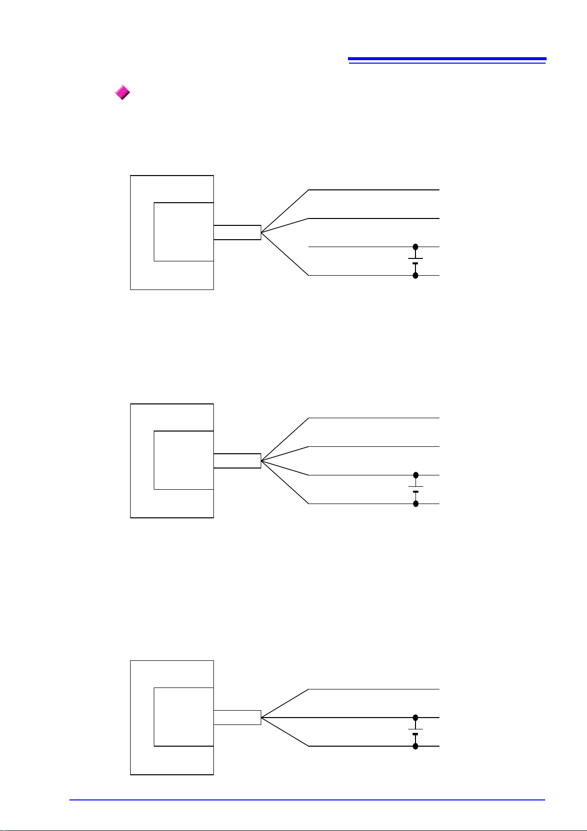
Red
Green
Black
Battery
Green
Black
Red
Battery
White
Black
Red
White
Battery
High-Speed CAN
Low-Speed CAN
Single-Wire CAN
CAN bus
CAN bus
CAN bus
Memory HiCorder
Model
MR8904
Model
MR8904
Model
MR8904
Model
9713-01
Model
9713-01
Model
9713-01
CAN-High
CAN-Low
GND
CAN-High
CAN-Low
GND
CAN
GND
Memory HiCorder
Memory HiCorder
3.2 Connecting the Unit to the Measurement Target
Connection diagram when using Model 9713-01
13

14
Depending on the environment, the dialog box may take some time to appear so please
wait till it does so.
Click
3.3 Connecting the Unit to a PC
3.3 Connecting the Unit to a PC
The MR8904 can be configured from a PC via the Memory HiCorder. Before starting the configuration
process, install the USB driver and connect the PC and Memory HiCorder.
Installing the USB driver
Install the USB driver before
Do not plug in or unplug the USB cable while the Memory HiCorder is operating.
Use a user account with administrator privileges to perform the installation.
Execute the [HiokiUsbCdcDriver.msi] file in the X:\Driver folder on the CD.
1
(“X” indicates the CD-ROM drive. T
Click [Next].
2
you use the Memory HiCorder with a USB connection.
he letter varies with the PC.)

Click [Next].
Click
Click
3
When you want to change the
installation destination
Click [Browse...] to change the folder to
install into. Normally, there is no need to
change.
Click [Next] to start installing.
4
15
3.3 Connecting the Unit to a PC
The installation of the software will begin.
16
Click
Click
1 Check
2 Click
Click
3.3 Connecting the Unit to a PC
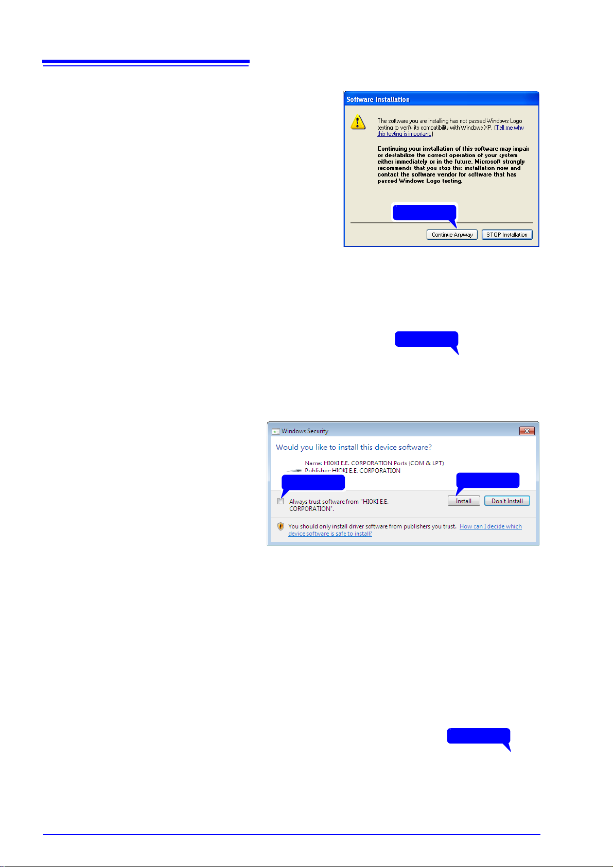
For Windows XP
During the installation, a message saying
that the software has not passed Windows
Logo testing will appear a few times, click
[Continue Anyway] to continue installing.
For Windows Vista/7/8
When a dialog box requesting your permission to continue the program appears,
click [Y
es].
Sometimes another dialog box requesting
your permission to install the software may
a
ppear. When it does, check [Always
trust software from "HIOKI E.E. CORPORATION"] and
ue.
When installation is completed
5
click [Install] to contin-
and the dialog box appears,
[Close] to exit.
click
This completes the driver installation.

3.3 Connecting the Unit to a PC
USB cable
MR8875
1 Connect one end of the USB cable to the
USB cable slot on the Memory HiCorder
while making sure the plug is oriented
correctly.
2 Connect the other end of the cable to a
USB port on the PC.
2 Click
1 Check
Connecting the Memory HiCorder and PC
PC Requirements: A personal computer running Windows XP, Vista, 7 or 8.
• To prevent a malfunction, do not disconnect the USB cable during communication.
• The Memory HiCorder and PC should be
grounded separately, potential difference between the ground points can cause malfunctions or damage when connecting the USB cable.
connected to the same earth ground. If
17
The first time you connect the Memory
PC to recognize the Memory HiCorder.
HiCorder and PC, perform the following procedure to enable the
For Windows Vista/7/8
The Memory HiCorder is recognized automatically, and the preparation to use the device completes.
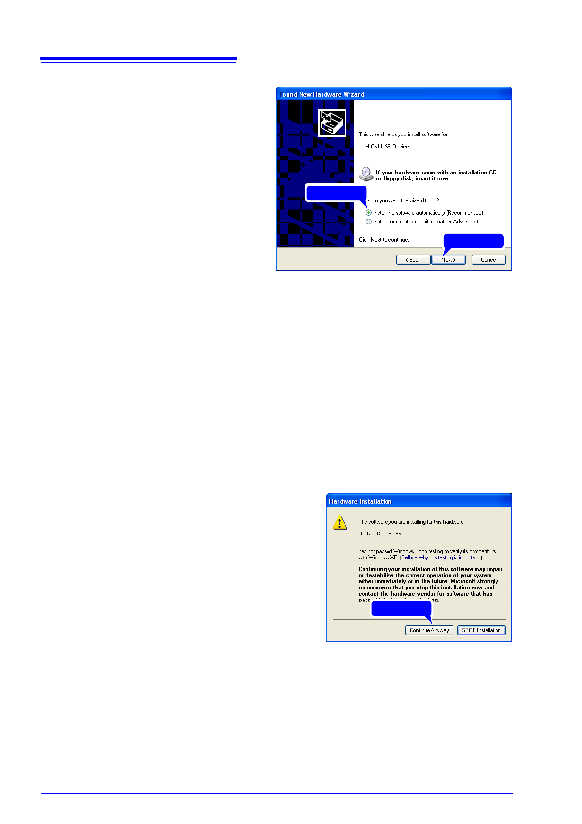
For Windows XP
A [Found New Hardware Wizard] dialog
box will appear and the new hardware de
tection wizard will begin.
Check [No, not this time] and
1
click
[Next].
-
18
2 Click
1 Check
Click
3.3 Connecting the Unit to a PC
Check [Install the software
2
automatically (Recommended)]
and click [Next].
Please wait while the driver is being installed.
Click [Continue Anyway].
3
A message saying that the software has
not passed Windows Logo testing will appear a few times, click [Cont
way] to continu
e installing.
inue Any-
 Loading...