

Page 1
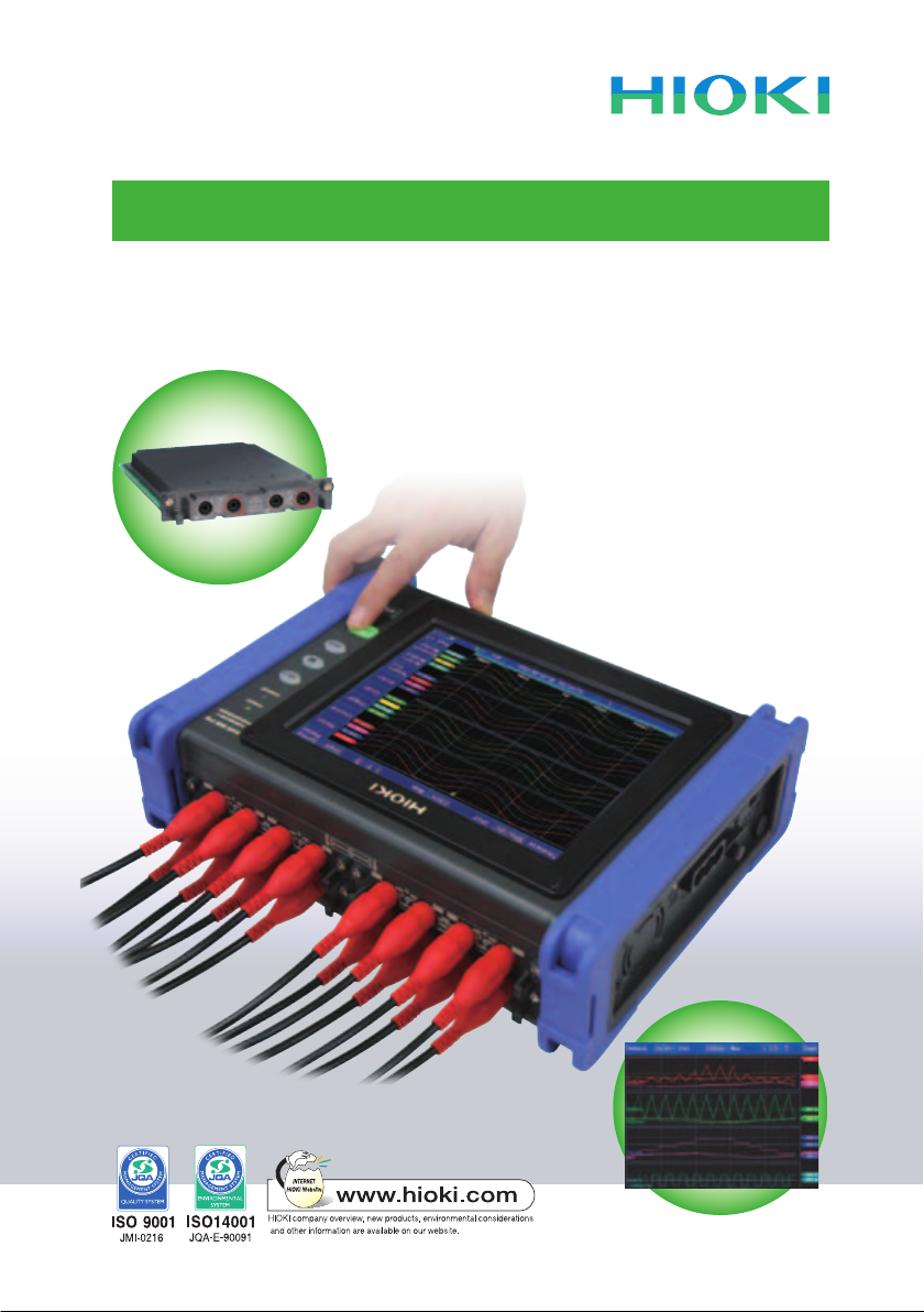
Introducing the Portable Multi-channel Data Acquisition Recorder
MEMORY HiCORDER MR8875
User Guide
Page 2

Table of Contents
Introduction ………………………………………………………………
1 What is the Memory HiCorder MR8875? …………………………
2 What types of input modules are available? ……………………
Analog Unit MR8905 -- High-voltage direct input
3
4
Analog Unit MR8901 -- Four-channel measurements
5
Voltage/Temp Unit MR8902 -- Measuring multiple temperature signals
6
Strain Unit MR8903 -- Measure miniscule voltage levels from strain
7
CAN Unit MR8904 -- Record CAN and analog signals simultaneously
8 Where can I use this? ………………………………………………
9 I want to record data from a solar power system ………………
10 I want to record signals from automobiles ………………………
11 I want to save high-speed data in real time ………………………
12 I want to record logic and pulse signals …………………………
13 Touch screen for intuitive operation ………………………………
14 What can I do with FFT analysis functions? ……………………
15 I want to use numerical/waveform calculation functions ………
16 What type of PC analysis software is available? …………………
17 What are the different data communication methods? …………
18 I need to congure the CAN settings………………………………
19 What level of environmental resistance does the MR8875 offer?
20 What accessories and options are available? …………………
21 Application Example 1 ………………………………………………
Magnetic eld measurement and FFT analysis
22 Application Example 2 ………………………………………………
Energy-saving measures for machine tools
23 Application Example 3 ………………………………………………
Phase synchronized testing at power plants
24 Application Example 4 ………………………………………………
Timing testing of circuit breakers at power plants and electrical
substations
………………………
…………………
P. 3
P. 4
P. 5
P. 6
P. 7
P. 8
P. 9
P. 10
P. 11
P. 12
P. 13
P. 14
P. 15
P. 16
P. 17
P. 18
P. 19
P. 20
P. 21
P. 22
P. 23
P. 24
P. 25
P. 26
P. 27
2
Page 3

Introduction
This user guide introduces the MR8875 Memory HiCorder’s various
characteristics and applications. It is designed to be used to extend
distributors’ and customers’ knowledge of the product.
3
Page 4
What is the Memory HiCorder MR8875?
1
The Memory HiCorder MR8875 provides capability for recording
16 high-speed analog channels and 8 logic signals in a compact,
A4-size footprint. It is Hioki’s rst Memory HiCorder model to
feature a touch panel to enable intuitive operation.
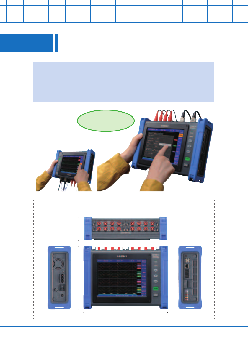
Simple touch
screen controls
Flip the screen when the
input terminals are positioned
at the bottom.
Full view
Left side:
Power connector
AC adapter outlet
Power port for
Differential Probes (x3)
Top:
Input module slots (for up to 4 modules)
84 mm
224 mm
298 mm
Right side:
Interface
SD Card slot
Logic input port
I/O port
4
Page 5
What types of input modules are available?
2
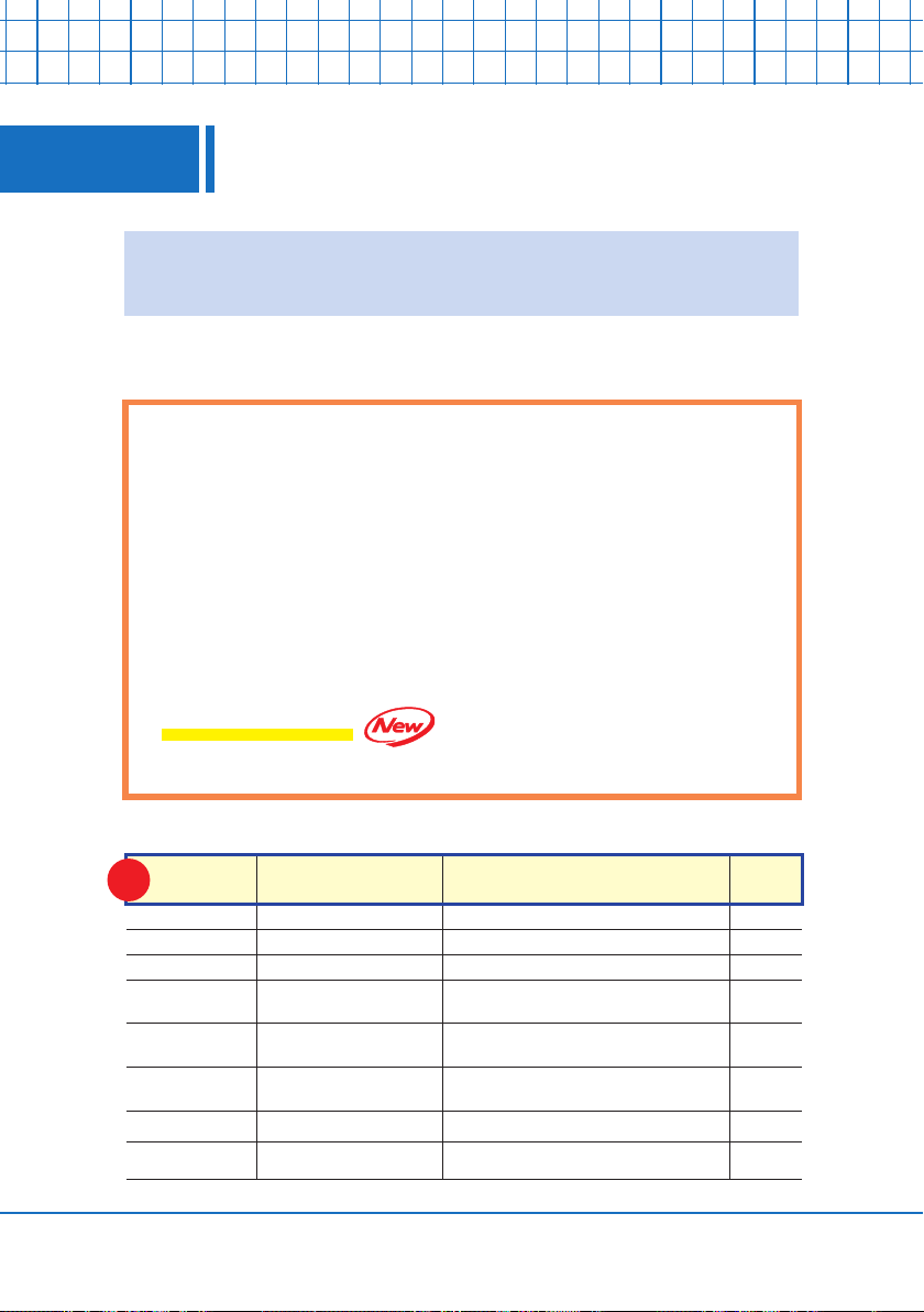
Five input modules are available: Analog Units (2 types), Voltage/
Temperature Unit, Strain Unit, and CAN Unit.
Install input modules according to your specic needs
(4 modules can be installed at the same time).
l Analog Unit MR8901
500 kS/s, 4 channels, 150 V DC isolated input
l Voltage/Temp Unit MR8902
100 S/s, 15 channels, up to 100 V, support 9 thermocouple types
l Strain Unit MR8903
200 kS/s, distortion/voltage 4 channels, converter cable included
l CAN Unit MR8904
Networking speed 10 k to 1 Mbps, equivalent of 15 analog channels
l Analog Unit MR8905
1000 V DC, 2 channels, 700 V AC direct input, RMS value measurements
Measurement signal Optional input module Measurement range Resolution
NEW
RMS AC
Temperature
(Thermocouple)
Distortion/Stress
CAN signal
Voltage
Voltage
Voltage
Voltage
Current
voltage
Analyze
Analog Unit MR8905
Analog Unit MR8901
Voltage/Temp Unit MR8902
Strain Unit MR8903
Analog Unit MR8901 +
Clamp on current sensor
Analog Unit MR8901 +
Differential Probe 9322
Voltage/Temp Unit MR8902
Strain Unit MR8903
CAN Unit MR8904
10 V f.s. to 1000 V f.s.
Observe instantaneous and RMS waveforms
100 mV f.s. to 200 V f.s. 4 µV
10 mV f.s. to 100 V f.s. 0.5 µV
1 mV f.s. to 20 mV f.s. 0.04 µV
Depends on current sensor(s) in use
* Certain current sensors require a separate power supply
100 V rms to 1 kV rms
200˚Cf.s.to2000˚Cf.s.
* Upper and lower limit values depend on the thermocouple in use
400 µε to 20,000 µε f.s. 0.016 µε
* 16bit analog signal: 15ch equivalent * Logic signal: 1bit/16ch equivalent
2 ports/unit
1/1250 div
1/1250 div
400 µV
0.01˚C
—
5
Page 6
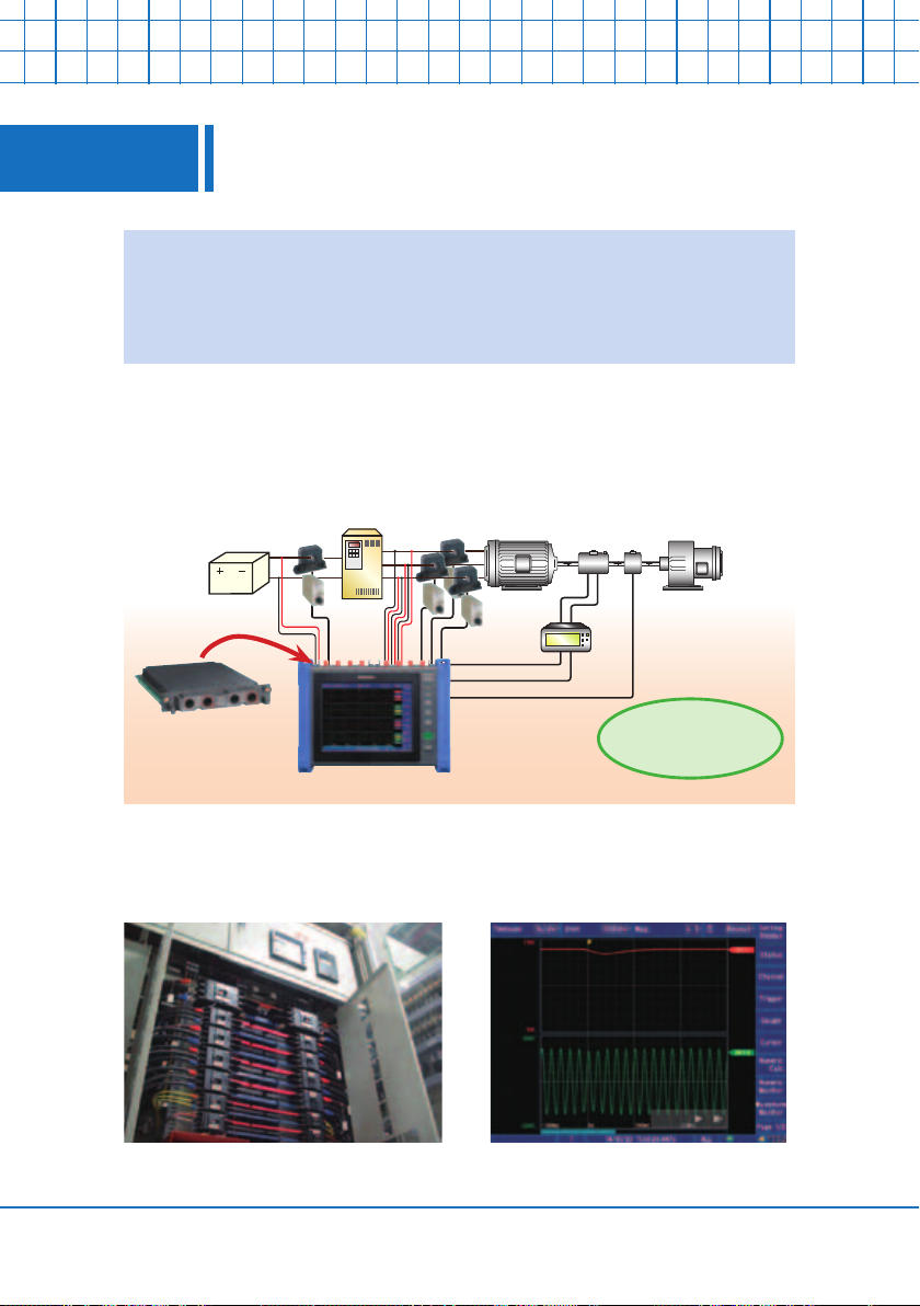
3
Analog Unit MR8905 -- High-voltage direct input
Directly input 1000 V DC and 700 V AC.
Plug the MR8905 into the Memory HiCorder to accommodate a broader range of applications requiring direct input in
CAT III (600 V) and CAT II (1000 V) environments.
The instrument is useful in applications that require recording of
waveforms for a vehicle’s inverter voltage or primary- and secondary-
side ground lines that cannot be combined as a single signal.
Battery
Analog Unit
MR8905
Inverter
Torque meter
Torque sensor
Encoder
Motor Load
Max 8ch high-
voltage recording
In factory environments, it can measure voltage owing on 400 V AC
power lines and record both instantaneous waveforms and RMS values.
6
Page 7
Analog Unit MR8901 -- Four-channel measurements
4
Directly input 150 V DC to accept direct input of 100 V AC power
supply waveforms. And since it provides four channels of input, it
can record twice as many phenomena as the MR8905.
Equipped with four MR8901 units, the MR8875 provides high-speed,
isolated recording capability for up to 16 channels.
Solar panel
Analog Unit
MR8901
DC
measurement
Power conditioner
DC measurement
Converter
Inverter
AC measurement
Commercial power system
Load
Since channels are isolated up to 100 V AC/DC, signals with different
potentials can be recorded at the same time.
Equipment power supply voltage (100 V AC) and control signals can
be recorded at the same time. The ability to use problematic phe-
nomena such as a power supply, control signal, or sensor output volt-
age as a trigger for recording is useful when analyzing the causes of
malfunctions.
7
Page 8
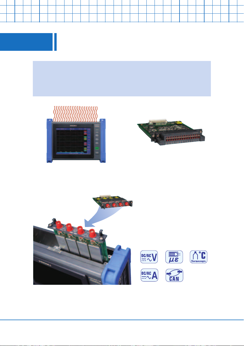
Voltage/Temp Unit MR8902 -- Measuring multiple
5
A single module lets you measure 15 channels of voltage or tem-
perature (using thermocouples). Temperature can be recorded
across up to 60 channels (with 4 modules installed) at a speed of
10 ms.
Mix-and-match different modules to simultaneously measure high
voltage, distortion, CAN signals, and more, alongside temperature.
temperature signals
Voltage/Temp Unit MR8902
The plug-in modules use an
input amplier structure.
Customers can freely add or
replace modules themselves.
8
Page 9
Strain Unit MR8903 -- Measure minuscule voltage
6
With frequency characteristics up to 20 kHz, you can use accel-
eration sensors to record vibration waveforms.
(Highest sampling rate: 200 kS/s) A bridge box and distortion
gauge can also be used to measure distortion. Real-time saving
lets you get distortion data over extended periods of time.
In addition to distortion measurement, a highly sensitive voltage
range makes the module perfect for measuring the voltages of
levels from strain
Ships standard with a
Tajimi’s conversion cable,
which is well known in
strain measurement.
Strain Unit MR8903
low-output voltage sensors.
The unit can be set as low as 50 μV/DIV (1 mV full scale).
The Strain Unit MR8903 is particularly useful for
measuring actinometers with low output voltages.
9
Page 10

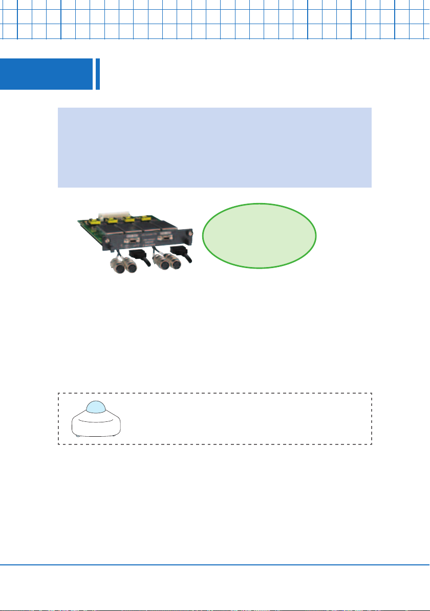
CAN Unit MR8904 -- Record CAN and analog
7
This module lets you record the CAN bus signals that are used
widely in automotive applications in the form of 15 channel analog
signals. Vector's CAN database can be loaded using supplied
software, allowing you to easily edit data.
signals simultaneously
CAN Unit MR8904
CAN signals and analog signals can be recorded
simultaneously on a single Memory HiCorder.
10
CAN Editor (bundled software)
Page 11

8
Where can I use this?
Industrial Robots
Voltage Temperature Strain Control Signals
The plug-in module-based architecture means
you can mix and record a variety of signals
across multiple channels. Ideal for verifying the
operation of multi-axis robots.
Sensor outputs
Strain
Example of
module
combinations
Motor current
Temperature variations on
movable parts
Control signal
(logic probe)
Analog Unit MR8901 x 2
Voltage/Temp Unit MR8902 x 1
Strain Unit MR8903 x 1
Development of Construction Machinery,
Agricultural Machinery, and Automobiles
Voltage Temperature Strain
Enhanced environmental temperature and vibration resistance enable the Memory HiCorder to
withstand harsh measurement environments.
R&D or Laboratory Experiments
Voltage Temperature
Multi-channel/long-term recording, useful in
performance/durability testing
- Record sensor output.
- Evaluate sensors and other devices.
- Use as an X-Y recorder (atbed).
Example of
module
combinations
Analog Unit MR8901 x 2
Voltage/Temp Unit MR8902 x 2
Testing of power equipment
Voltage Temperature Control Signals
1000 V DC and 700 V AC direct input
Test electrical power equipment
Example of
module
combinations
Analog Unit MR8901 x 1
Voltage/Temp Unit MR8902 x 1
Strain Unit MR8903 x 1
CAN Unit MR8904 x 1
Load rejection testing
Analyze the correlations among factors such as the
generator voltage before and after circuit-breaker operation,
degree of variability in RPM, governor servo operating
status, and pressure regulator operation
Example of
module
combinations
Analog Unit MR8901 x 2
Voltage/Temp Unit MR8902 x 2
timing.
11
Page 12

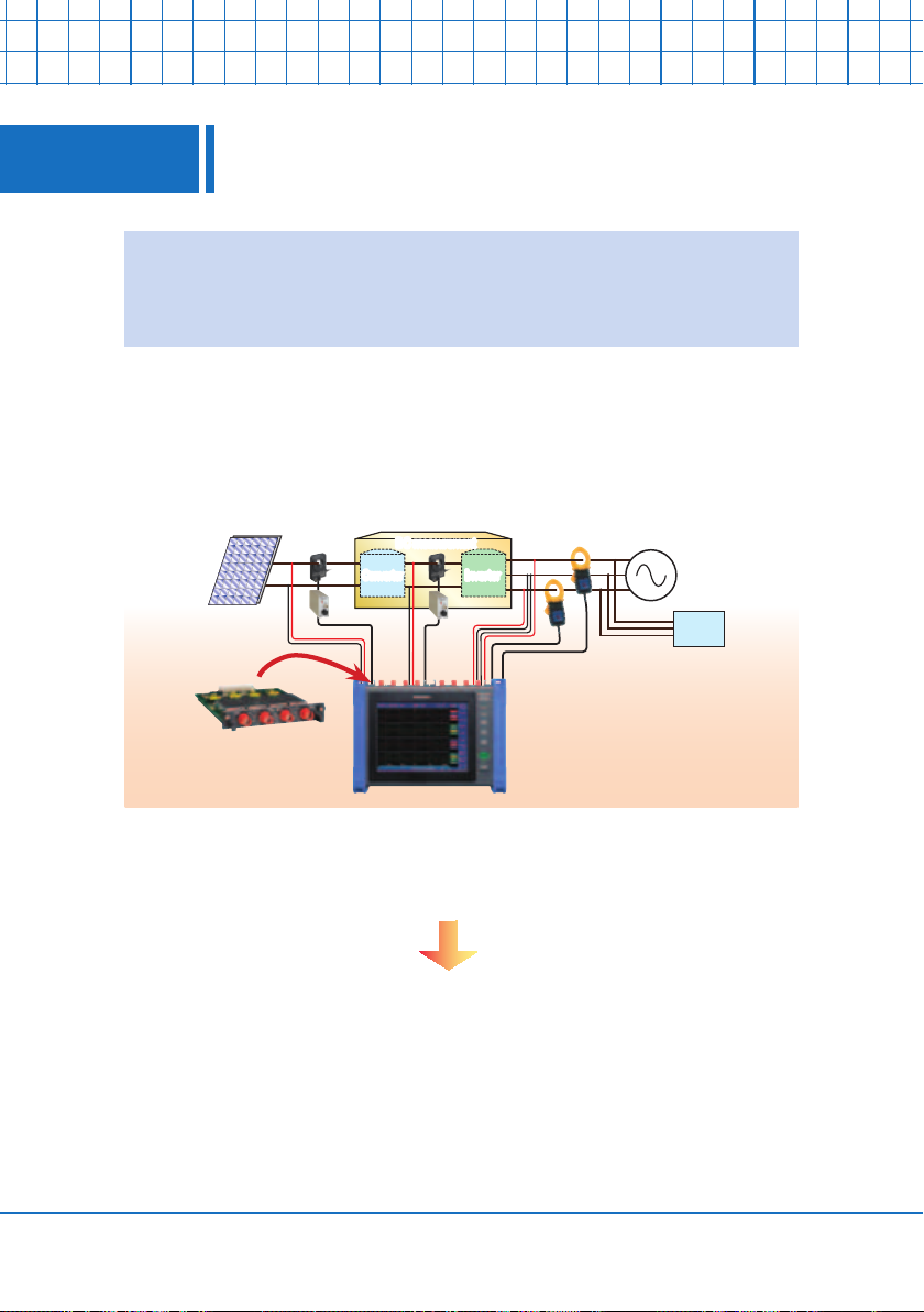
I want to record data from a solar power system
9
The Memory HiCorder can measure solar power systems using an
actinometer. With the Analog Unit MR8905, you can directly input
up to 1000 V DC.
Connector box
Voltage Current
Solar radiation
Temperature
12
Voltage
Used when measured voltage exceeds 1000 V DC (up to 2000
V DC). (When using the Analog Unit MR8901, utilize the differential probe with voltages in excess of 150 V DC.)
Current
Two types of sensors are available: CT9692 (20/200 A) and
CT9693 (200/2000 A).
Temperature
Use any length necessary.
Solar radiation
Measure solar radiation.
Differential Probe
AC/DC Clamp On Sensors
with thermocouple
with actinometer
Page 13

I want to record signals from automobiles
10
16 channels of high-speed analog signal recording lets you pick up
data from inside the vehicle.
seat to monitor waveforms over time.
Place on the dashboard or passenger
Sensor output
voltage, etc.
Place on the dashboard or passenger
seat to monitor waveforms over time
Current,
temperature, etc.
CAN signals, etc.
13
Page 14

I want to save high-speed data in real time
11
You can record high-resolution data in real time to an SD memory
card. At the fastest 2 μsec cycle, you can record approximately 36
minutes of data to a 2 GB SD Card at 1-channel settings.
Input
25000 pts
Min 2 μsec (Sampling rate: 500 kS/s)
A/D conversion
Isolated
Load to internal storage
Sampling rate: 500 kS/s simultaneously across all channels
(2 μsec cycle)
16bit resolution (25000 points)
8 million data/module
Input
A/D conversion
Min 2 μsec (Sampling rate: 500 kS/s)
Isolated
Write to SD memory
card in real time
14
Super high-speed data saving
60-channel recording possible with a sampling rate of 50 μs or less.
Operation is guaranteed only with a genuine Hioki SD memory card.
Page 15

I want to record logic and pulse signals
12
The instrument ships standard with recording terminals for eight
channels of logic signal input and two channels of pulse signal input.
Since the instrument is built in with terminals for pulse input and logic
probe input, input modules can be used exclusively to record analog
signals.
Analog signals
recorded by input unit
Logic probe terminals
Use to record ON/OFF (logic) signal
waveforms of a relay and PLC.
Logic Probe 9320-01 Logic Probe MR9321-01
For low voltage equipment; for
voltage/contact signal ON/OFF
detection up to 50 V DC, GND
shared across channels
2 pulse inputs (shared GND)
Pulse signals indicating
quantities such as RPM and
ow rate can also be recorded
(counted).
Side of
HiCorder
For high voltage equipment; for ON/OFF
detection of 100 V/200 V AC/DC line
voltages, isolated inputs for all channels
15
Page 16

Touch screen for intuitive operation
13
Operation is intuitive since the user touches the screen directly
to control the instrument. This approach yields a dramatic
improvement in convenience in the eld. In addition, the number of
hardware buttons on the instrument has been minimized, allowing
the screen to be enlarged.
l Backscroll display
Display past waveforms during
measurement without losing any
records.
l Advanced cursor read functions
Six cursors marked A through F
are available, compared with the
conventional A- and B-cursors. This
is useful for multi-channel waveform
analysis.
16
l Split screen and sheet display
The waveform screen can be divided
into four windows, and you can also
dene up to four sheet displays.
l
Event marker input and jump function
Up to 1000 event markers can be
entered. You can quickly jump to
any mark location, letting you quickly
search for the area you want.
Page 17

What can I do with FFT analysis functions?
14
The MR8875 has featured FFT analysis functions since version 2.01.
A variety of features are included to support analysis.
l 4-channel FFT analysis function
FFT analysis can be carried out for
one input or simultaneously for up
to four inputs, allowing analysis of
frequency components occurring at a
single point in time on a channel-by-
channel basis.
l Peak value display function
Up to 10 analyzed waveform peaks
can be calculated and displayed at
once.
l Running spectrum display function
This function can be used to
continuously display spectra that
change over time. The 3D display
shows you how things are changing.
l Overlay display function
This function can be used to observe
variations in waveforms captured
using continuous measurement over
time.
17
Page 18

I want to use numerical/waveform calculation
15
The MR8875 has featured waveform operation functions since
version 2.01. A combination of up to 8 calculations selected from
the instrument’s 25 numerical calculations and 24 waveform calcu-
lations can be performed simultaneously.
Numerical calculation settings screen Waveform calculation settings screen
functions
8 calculations
at once
18
l
Real-time inter-channel calculation
This function allows you to observe
and record results for up to two
calculations on the same input
module while measurement
continues.
l Digital lter calculations
This function allows the necessary
bandwidth portion of a waveform
containing noise to be calculated and
the resulting waveform displayed.
CH-1 measured waveform
CH-2 measured waveform
Real-time waveform calculation results
Measurement
results of
distorted
waveform
containing
noise
Simulated results
after passing through
a low-pass lter
to remove highfrequency distortion
H.P.F. - calculated
waveform
B.P.F. - calculated waveform
L.P.F. calculated
waveform
Page 19

What type of PC analysis software is available?
16
The WaveViewer (Wv) PC application software is bundled with the
MR8875. Other powerful software includes Wave Processor 9335
(option) and CAN Editor, useful for CAN signal measurement.
WaveViewer Wv (bundled software)
Free software included with MR8875
- Simple waveform file display
- Text conversion (CSV)
- Display format customization
Download the latest version of the WaveViewer
from the HIOKI website at www.hioki.com.
Wave Processor 9335 (option)
Offers more advanced features than WaveViewer Wv
- Waveform display
- Text conversion (CSV)
- File load
9335-only features
- Display format settings
(X-Y display)
- Freely expand time
axis/direction
- Numerical calculations
- Printing
CAN Editor (bundled software)
Free software included with MR8875
For more details, refer to “I need to
configure CAN settings (P. 21)”.
19
Page 20

What are the different data communication methods?
17
l LAN and USB interfaces
Take advantage of the built-in
100BASE-TX LAN and USB 2.0
Mini-B interfaces to network with
LAN
the PC.
l A variety of network functions
Remotely control the MR8875 and transfer data using the LAN network.
USB
Remote control via Web server
Receive data via FTP
Send data via FTP
Attach data to
E-mail
l SD memory cards/USB memory
Convenient SD memory cards or USB
memory sticks can be used to copy
data from the MR8875’s internal storage
memory. Data stored in the MR8875’s SD
card can also be downloaded to the PC
using a USB cable.
While it is possible to save to USB memory stick, we recommend using ofcial HIOKI SD memory
cards to ensure against data loss.
SD memory card
USB memory
20
Page 21

I need to configure the CAN settings
18
You can create data with the supplied CAN Editor software.
Using this software allows you to load Vector’s CAN database.
CAN Editor (bundled software)
Industry standard CANdb database les can be loaded into the sup-
plied setting software and associated to the CAN channel signals.
21
Page 22

What level of environmental resistance does the
19
l Wide operating temperature range
The operating temperature range is wider
than its legacy products; from -10
o
C, making measurement possible even
50
in hostile environment.
Many measuring instruments work
at an operating temperature range
of 0
l Improved anti-shock capability
The MR8875 is compliant with the
JIS D1601 for vibration resistance
performance and is designed to
withstand the harsh conditions for invehicle measurement.
MR8875 offer?
o
C to 40 oC.
o
C to
22
l Data saved securely, even when the power's out
Even if power is cut while the MR8875 is saving data in real time, an internal
high-capacity capacitor retains power until the data save is complete.
* For genuine Hioki SD memory cards only.
MR8875
!
power cut
Data protected!
Automatically restart
measurement when the
power's back on
Page 23

20
What accessories and options are available?
l Battery Pack Z1003
Large storage: 7.2 V at 4500 mAh
Continuous operating time: Approx.
1 hour with backlight on
l
DC power cord
An optional power cord terminating
in bare wires.
Connects to 12 V/24 V external
power supplies.
l
Differential Probe 9322
Measure 2000 V DC or 1000 V AC
with the Analog Unit MR8901.
Rear of
MR8875
Battery pack ts securely
in rear
External
power supply
l
Current measurements
A wide selection of optional sensors are available, from commercial frequency current to DC and high-frequency current probes.
Leak current/load current
measurement
Current waveform observation
23
Page 24

Application Example 1
21
Development of high-output train cars and electric vehicles is leading to
stronger magnetic elds in the passenger spaces of train cars and in auto-
mobiles. The strength of a given magnetic eld varies with the output (cur-
rent) of the motor producing it. By using the Memory HiCorder MR8875
in conjunction with a magnetic eld tester, it is possible not only to record
measurements of instantaneous values while stopped and time-axis mea-
surements of magnetic elds during operation, but also to perform simul-
taneous three-axis FFT analysis (for the X-, Y- and Z-axes).
Magnetic eld measurement and FFT analysis
24
FFT analysis provides an understanding of operating frequencies so that
you can estimate which equipment is producing magnetic elds, allowing
implementation of effective countermeasures such as shielding.
Page 25

Application Example 2
22
The Memory HiCorder MR8875 can be used to monitor the power (motor
power, heater power, etc.) for individual manufacturing (molding) process-
es. By using the Voltage/Temp Unit MR8902, it is also possible to simulta-
neously record heater temperature waveforms.
Energy-saving measures for machine tools
Sensor output
signals
Machine
power
consumption
Clamp-on power
HiTester 3169-21
1. Record process signals from a machine tool as logic signal waveforms from
logic probes with the Memory HiCorder MR8875.
2. Measure motor power or heater power with the Clamp On Power HiTester
3169-01 and record that instrument’s analog signal output with the MR8875.
3. By carrying out a comparative analysis of the resulting waveforms
and optimizing machine tool parameters such as voltage and ow rate
accordingly, you can reduce the amount of energy used by the equipment.
Process signals
Logic Probe
9320-01
Memory HiCorder
MR8875
Analog
signal
Logic signal
25
Page 26

Application Example 3
23
23
The MR8875 can be used to conduct Phase Synchronized Testing
when connecting generators to power circuits.
When connecting output from a generator to a power circuit, it is necessary to match the phases
of the generator output with the phases of the power circuit. Commands should be issued to
the synchronization equipment so that the generator is connected to the circuit when the beat
voltage, which indicates the phase difference, reaches its minimum value.
The MR8875 MEMORY HiCORDER can be used to capture the command signal, contact
operation, beat voltage, and current owing from the generator to the power circuit.
This type of testing is necessary when departments involved with generation at power
companies deploy new circuit breakers and synchronization equipment, and during maintenance
of that equipment.
Personnel observe the timing at which the circuit breaker contact operation and beat voltage
converge based on the input command from the synchronization equipment and verify that
operation falls within specications.
Phase synchronized testing at power plants
26
Synchronization
equipment
Generator
CT PT PT
Load current
Contact operation can be checked using the MR9321-01
Logic Probe, and the load current can be checked
using the CT9691-90 AC/DC Sensor.
The instrument is compact and can be used with an optional battery and printer, making it easy
to transport in the eld.
The instrument’s scaling function can be used to directly read PT/CT primary-side values.
Analog input channels are isolated, and there is no need to use a common ground as with an
oscilloscope.
*Maximum ratings: 600 V AC/DC terminal-to-terminal, 600 V AC/DC terminal-to-ground
Circuit
breaker
Beat voltage
Synchronization signal
Circuit breaker contact
(Power
circuit)
Verify the timing of
contact operation,
beat voltage, and
load current.
Synchronization signal
Circuit breaker contact
Beat voltage
Load current
Page 27

Application Example 4
2424
The MR8875 Memory HiCorder can be used to test the operational timing
of circuit breakers (switches) at power plants and electrical substations.
This capability can be used when deploying new circuit breakers and during regular testing of
circuit breakers at power plants and electrical substations.
Using the introduction of the command current as the reference, check the operational timing for
each phase contact as well as the operational variation time for each phase and verify that the
obtained values are within specications.
This capability is used by power companies’ generation and distribution maintenance groups
and by electrical companies that perform contract work for power companies.
Isolate
Timing testing of circuit breakers (switches) at power
plants and electrical substations
Time from introduction of command
current until each phase contact operates
Isolate
Circuit breaker
control panel
Variation in the contact operating times
for each phase
Contact operation
Ground
for safety
Command
current
Contact operation can be checked using the 9320-01 Logic Probe, and the command current
can be checked using the CT9691-90 AC/DC Sensor.
The instrument is compact and can be used with an optional battery and printer, making it easy
to transport in the eld.
Analog input channels are isolated, and there is no need to use a common ground as with an
oscilloscope.
*Maximum ratings: 600 V AC/DC terminal-to-terminal, 600 V AC/DC terminal-to-ground
Command current
Supply voltage
27
Page 28

HEADQUARTERS:
81 Koizumi, Ued a, Nagano, 386 -1192, Japan
TEL +81-268-28-0562 FAX +81-268-28-0568
http://www.hioki.com / E-mail: os-com@hioki.co.jp
HIOKI USA CORPORATION:
TEL +1-609-409-9109 FAX +1-609-409-9108
http://www.hiokiusa.com / E-mail: hioki@hiokiusa.com
HIOKI ( Shangh ai) SALES & TRADING CO., LTD.:
TEL +86-21-63910090 FAX +86-21-63910360
http://www.hioki.cn / E-mail: info@hioki.com.cn
HIOKI INDIA PRIVATE LIMITED:
TEL +91-124- 6590 210 FA X +91-124- 6460 113
E-mail: hioki@ hioki.in
HIOKI SINGAPORE PTE. LTD.:
TEL +65-66 34-7677 FAX +65-6 634-7477
E-mail: info-sg@hioki.com.sg
HIOKI E . E. CORPORATION
Seoul Representative Office :
TEL +82-2-2183-88 47 FAX +82-2-2183-3360
Note:
Compa ny names and P roduct nam es appear ing in this cat alog are trad emarks or r egistere d trademarks of vario us compani es.
All infor mation cor rect as of Oct . 10, 2014. All speci cations are subject to c hange witho ut notice.
UG_MR8875E1-4XB
 Loading...