

Page 1
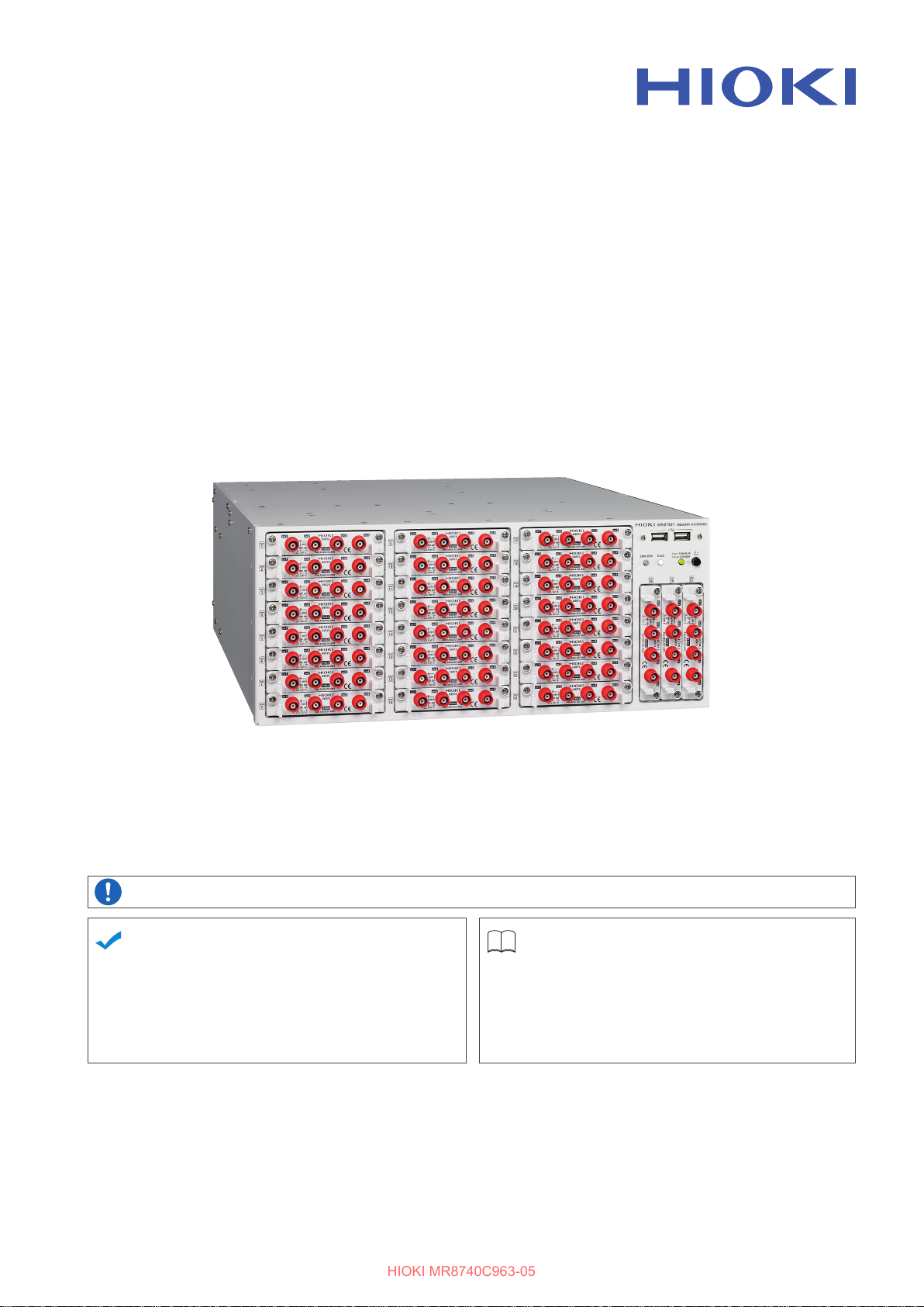
MR8740T
HIOKI MR8740C963-05
MR8740-50
Quick Start Manual
MEMORY HiCORDER
Be sure to read this manual before using the instrument.
When using the instrument for
the rst time
Name and Function of
Each Part
Measurement Method
Oct. 2021 Revised edition 5
MR8740C963-05 21-10H
Troubleshooting
Maintenance and Service
p. 24
Troubleshooting
p. 69 Message
p. 6
p. 149
p. 151
p. 154
EN
*600530255*
Page 2

HIOKI MR8740C963-05
Page 3
FAQs
HIOKI MR8740C963-05
To set the measurement range automatically
Refer to “3.7 Measuring Signals With the Auto-range Setting” (p. 80).
To change the measurement range
Refer to “Analog channel” (p. 73).
To add a comment to the data
Refer to “Analog channel” (p. 73).
To minimize inuence of noise (Low-pass lter, LPF)
Refer to “Analog channel” (p. 73).
To change the sampling rate
Refer to “3.2 Setting Measurement Conditions” (p. 70).
To congure the trigger settings
Refer to “3.4 Conguring the Level Trigger Settings” (p. 75).
To scroll through the waveform display
Refer to “4.2 Handling Waveforms” (p. 85).
To read measured values (cursor values) with cursors
Refer to “4.1 Reading Measured Values (Trace Cursors)” (p. 83).
To save data les
Refer to “3.6 Saving Data Consisting of Items Selected” (p. 78).
To estimate le size
Refer to “13.1 Information for Reference Purposes” of Instruction Manual.
To open data les with a computer
Refer to “4.3 Loading Data With Your Computer (Wave Viewer)” (p. 86).
MR8740C963-05
Page 4
Measurement Procedure
HIOKI MR8740C963-05
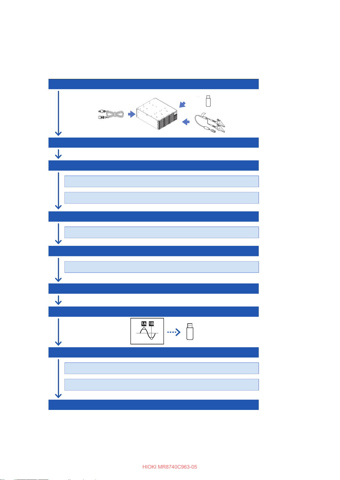
The basic measurement procedure is as follows. For advanced use, refer to the Instruction Manual
(PDF) in the accompanying CD.
Preparing for measurement
Inspecting the instrument before measurement
Conguring the basic settings for measurement
Choose a sampling rate.
Choose a recording length (shot).
Conguring the input channel settings
Congure the analog channel settings.
(p. 35)
(p. 69)
(p. 70)
(p. 72)
Conguring the trigger settings
Congure the trigger settings.
Starting/Stopping measurement
Saving measured data les
Analyzing waveforms
Scroll through, zoom in, and zoom out waveforms.
Read measured values (with the trace cursors).
Finishing the measurement
(p. 75)
(p. 77)
(p. 78)
(p. 83)
Page 5
Contents
HIOKI MR8740C963-05
Introduction
Symbols and abbreviations
Conrming Package Contents
Safety Information
Operation Precautions
How to Refer to This Document
........................................................1
.............................2
........................4
............................................6
.....................................8
...................21
1 Overview 23
1.1 Product Overview and Features
1.2 Name and Function of Each Part
1.3 Screen
Screen conguration
Explanation of each screen
1.4 Basic Operation
Mouse operation
Changing screens and settings
Help Function
(Displaying Instruction Manual)
....................................................28
.................................28
.......................29
....................................31
.......................................31
.........23
.......24
.................32
.................34
2 Preparing for
Measurement
35
Turning o the instrument
2.7 Setting the Clock
..........................64
..................................65
2.8 Regulating the Zero Position
(Zero-Adjustment)
................................66
2.9 Executing Calibration
(For the Instrument With Model
MR8990 Installed)
................................68
3 Measurement Method 69
3.1 Inspection Before Measurement
3.2 Setting Measurement Conditions
Sampling rate setting guideline
3.3 Conguring the Input Channel
Settings
Analog channel
..................................................72
.........................................73
3.4 Conguring the Level Trigger
Settings
..................................................75
3.5 Starting/Stopping Measurement
3.6 Saving Data Consisting of Items
Selected
.................................................78
3.7 Measuring Signals With the Autorange Setting
.........................................80
........69
.......70
..................71
.........77
2.1 Installing and Removing Modules
Allocation of modules and channels
2.2 Attaching Connection Cords
Connection cables
(For measuring voltage, frequency,
or rotation speed, and obtaining
accumulations)
Thermocouple (Temperature)
Strain gauge transducer
Current sensor
Acceleration sensor
Logic probe (Measuring logic signals)
Connection cable
(For precisely measuring voltage)
Outputting waveforms
Outputting pulse waveforms
Outputting voltage, current, and
resistance
Connection cable (high voltage)
.........................................40
............................43
..........................................45
..................................49
...............................52
......................53
.................................................54
...........37
...............38
....................42
........51
..............51
................55
2.3 Connecting the External Control
Terminals
...............................................56
2.4 Connecting the Instrument with
computers
..............................................58
2.5 Preparing Storage Devices
(Recording Media)
USB ash drive
Built-in drive
Removing storage devices
Formatting storage devices
..............................................60
................................60
.........................................60
........................61
.......................62
2.6 Supplying Power to the Instrument
Turning on the instrument
.........................63
......36
....63
4 Analysis Method 83
4.1 Reading Measured Values
(Trace Cursors)
4.2 Handling Waveforms
Scrolling through waveforms
Zooming in and out waveforms
.....................................83
............................85
.....................85
..................85
4.3 Loading Data With Your Computer
(Wave Viewer)
.......................................86
5 Specications 89
5.1 Specications of Model MR8740T
General specications
Trigger
......................................................94
Waveform screen
Setting screen
File
...........................................................99
Performing calculation
Memory division
Waveform search
Others
....................................................101
..........................................97
...............................89
......................................96
.............................100
......................................101
....................................101
5.2 Specications of the Options
Model 8966 Analog Unit
Model 8967 Temp Unit
Model 8968 High Resolution Unit
Model U8969 Strain Unit
Model 8970 Freq Unit
Model 8971 Current Unit
..........................103
............................105
.........................109
............................. 111
......................... 113
.....89
............103
............107
i
Page 6

Contents
HIOKI MR8740C963-05
Model 8972 DC/RMS Unit
Model 8973 Logic Unit
Model MR8990 Digital Voltmeter Unit
Model U8974 High Voltage Unit
Model U8975 4ch Analog Unit
Model U8977 3CH Current Unit
Model U8978 4CH Analog Unit
Model U8979 Charge Unit
Model U8991 Digital Voltmeter Unit
Model MR8790 Waveform Generator
Unit
........................................................134
Model MR8791 Pulse Generator Unit
Model U8793 Arbitrary Waveform
Generator Unit
Model U8794 VIR Generator Unit
........................................139
....................... 115
............................117
.................122
................127
.......................129
6 Maintenance and
Service
6.1 Troubleshooting
Before sending the instrument for repair
6.2 Initializing the Instrument
6.3 Message
Error messages
Warning messages
6.4 Self-check
Memory check
LAN check
Media check
System conguration check
6.5 Cleaning the Instrument
6.6 Disposing of the Instrument
(Removing the lithium battery)
149
..................................151
...................153
..............................................154
......................................155
.................................156
............................................160
........................................160
..............................................161
...........................................163
.....................164
....................165
......118
...............120
...............124
.........132
......136
............143
..151
..........165
7 Appendix 167
7.1 Mounting the instrument in a rack
Rack-mount brackets
How to secure the rack-mount brackets
Index 169
Warranty Certicate
ii
....167
..............................167
...168
Page 7
Introduction
HIOKI MR8740C963-05
Thank you for choosing the Hioki MR8740T Memory HiCorder (Model MR8740-50). Preserve this
manual carefully and keep it handy to make full use of this instrument for a long time.
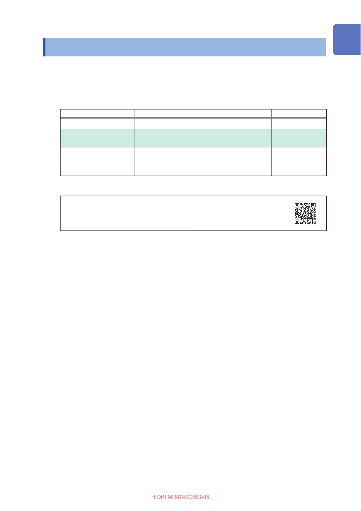
Following manuals are provided along with these models. Refer to manuals relevant to your
purpose.
Type Contents Printed PDF
Operating Precautions Information on the instrument for safe operation
Introduction
–
Quick Start Manual
(This document)
Instruction Manual Functions and instructions for the instrument –
Instruction Manual
U8793, MR8790, MR8791
Basic instructions and specications of the instrument
Functions, specications, and instructions for the
U8793, MR8790, and MR8791
–
Latest instruction manual
The contents of this manual are subject to change, for example as a result of
product improvements or changes to specications.
The latest edition can be downloaded from Hioki’s website.
https://www.hioki.com/global/support/download
Target audience
This manual has been written for use by individuals who use the product in question or who teach
others to do so.
It is assumed that the reader possesses basic electrical knowledge (equivalent to that of someone
who graduated from the electrical program at a technical high school).
Trademarks
• Microsoft and Internet Explorer are either registered trademarks or trademarks of Microsoft
Corporation in the United States and other countries.
• Other products and company names are trade names, registered trademarks, or trademarks of
their respective owners.
–
1
Page 8
Symbols and abbreviations
HIOKI MR8740C963-05
Symbols and abbreviations
Safety notations
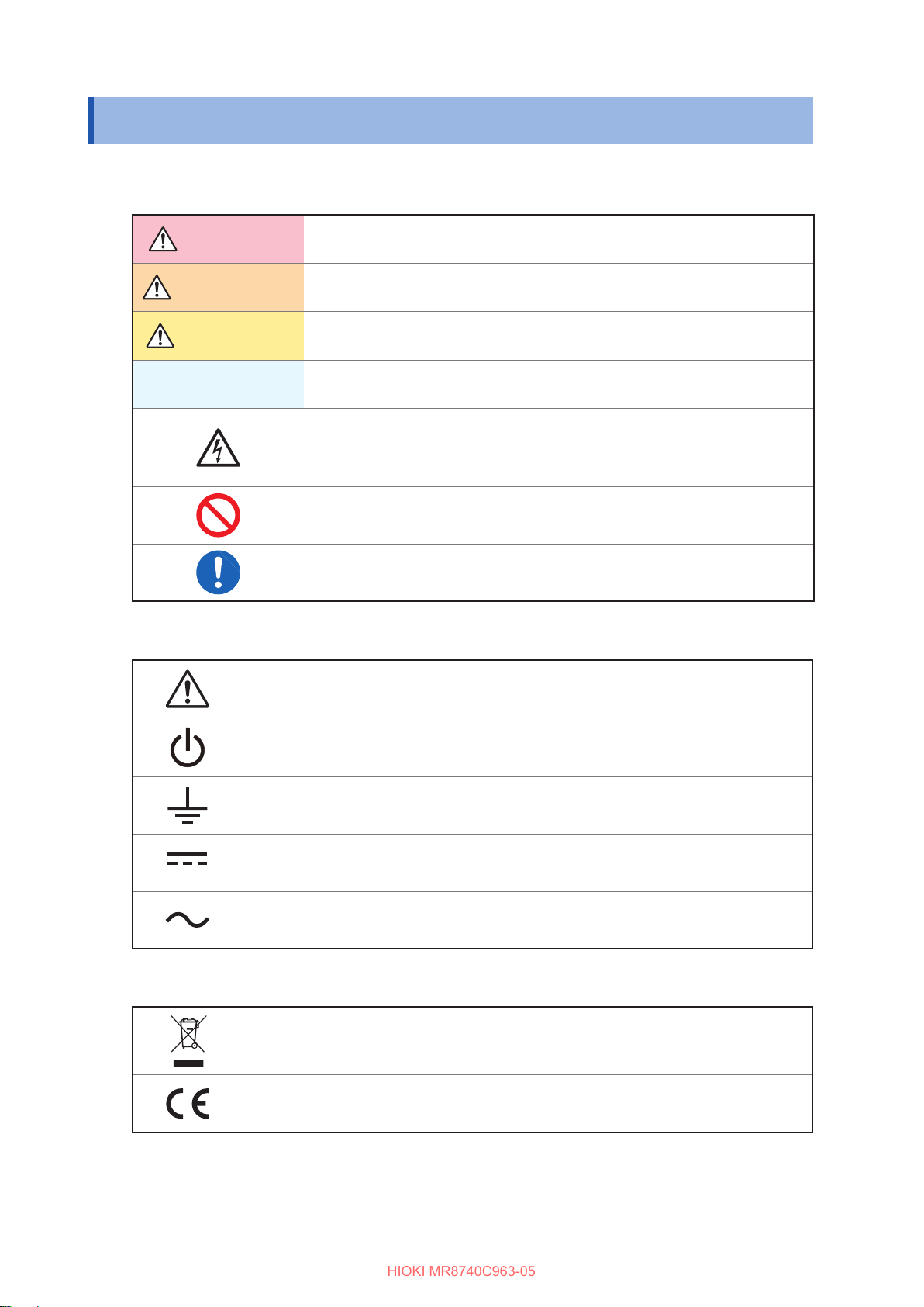
In this document, the risk seriousness and the hazard levels are classied as follows.
DANGER
WARNING
CAUTION
IMPORTANT
Indicates an imminently hazardous situation that will result in death or serious
injury to the operator.
Indicates a potentially hazardous situation that may result in death or serious
injury to the operator.
Indicates a potentially hazardous situation that may result in minor or moderate
injury to the operator or damage to the instrument or malfunction.
Indicates information related to the operation of the instrument or maintenance
tasks with which the operators must be fully familiar.
Indicates a high voltage hazard.
If a particular safety check is not performed or the instrument is mishandled,
this may give rise to a hazardous situation; the operator may receive an electric
shock, may get burnt or may even be fatally injured.
Indicates prohibited action.
Indicates the action which must be performed.
Symbols axed to the instrument
Indicates cautions and hazards. When the symbol appears on the instrument, read the
corresponding topic in the Instruction Manual.
Indicates the power button that switches the instrument between on and o states.
Indicates a grounding terminal.
Indicates DC (direct current).
Indicates AC (alternating current).
Symbols for Standards
Indicates the Waste Electrical and Electronic Equipment Directive (WEEE Directive) in EU
member states.
Indicates that the product conforms to regulations set out by the EU Directive.
2
Page 9
Others
HIOKI MR8740C963-05
Symbols and abbreviations
*
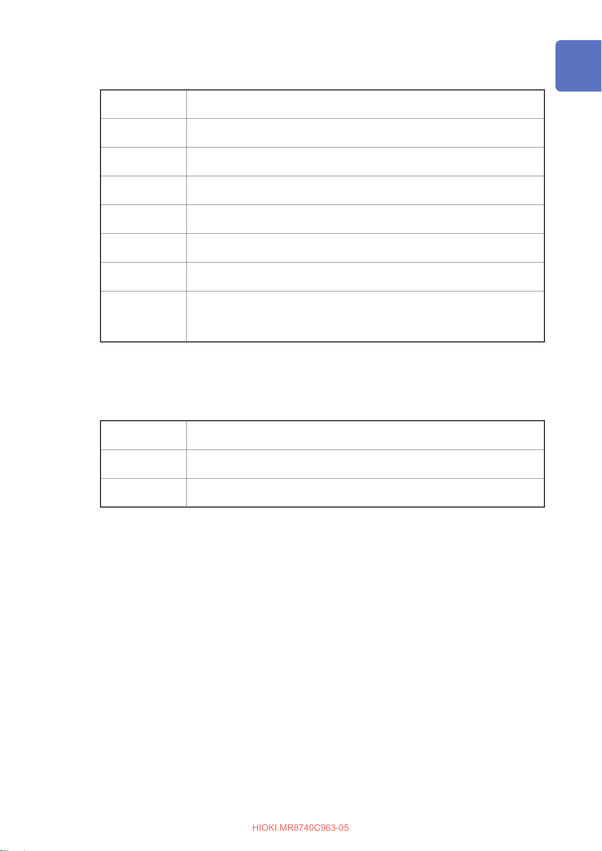
(p. ) Indicates the location of reference information.
START
(Bold-faced)
[ ]
Windows
Current sensor Sensors measuring current are referred to as “current sensor.”
S/s
Additional information is presented below.
Indicates the initial setting values of the items. Initializing the instrument restores
settings to each of these values.
Names and keys on the screen are indicated in boldface.
Menus, dialog boxes, buttons in a dialog box, and other names on the screen are
indicated in brackets ([ ]).
Unless otherwise specied, “Windows” represents Windows 7, Windows 8, and
Windows 10.
The number of times per second the analog input signals are digitized by the
instrument is represented in “samples per second (S/s).”
Example: “20 MS/s” (20 megasamples per second) indicates that the signal is digitized
20 × 106 times per second.
Notations
We dene measurement tolerances in terms of f.s. (full scale) and rdg. (reading) values, with the
following meanings:
f.s.
rdg.
setting
(maximum display value or scale length)
The maximum displayable value or scale length.
(displayed value)
The value currently being measured and displayed on the measuring instrument.
(setting value)
Indicates the value set as the output voltage, current, or other quantity.
3
Page 10
Conrming Package Contents
HIOKI MR8740C963-05
Conrming Package Contents
When you open the package, inspect the instrument carefully to ensure that everything is in good
condition, and that no damage occurred during shipping. Carefully check the accessories, panel
keys and switches, and connectors. If the instrument seems to have been damaged or does not
work as specied, contact your authorized Hioki distributor or reseller.
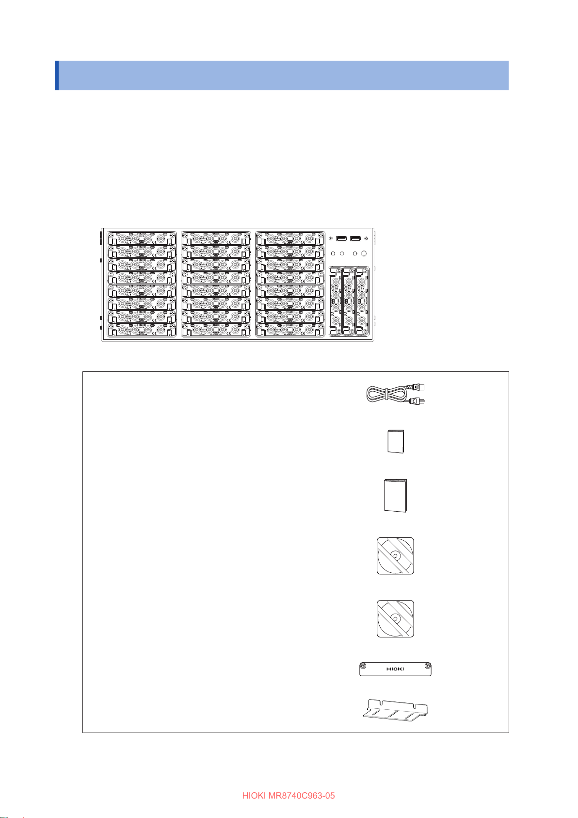
Check that the package contents are correct.
Instrument
Model MR8740T Memory HiCorder
Accessories
Power cord
Operating Precautions (0990A903)
Quick Start Manual (This document)
Instruction Manual CD*
• Instruction Manual
MR8740C964-xx.pdf
Application disc*
(p. 63)
1
(p. 34)
1
(p. 86)
*1: The latest version can be downloaded from our website.
4
Blank panel (for slots with no module installed)
Rack-mount brackets
(p. 36)
(p. 167)
Page 11

Conrming Package Contents
HIOKI MR8740C963-05
Options (sold separately)
The options listed below are available for the instrument. To order an option, please contact your
authorized Hioki distributor or reseller. Options are subject to change. Please check Hioki’s website for the
latest information.
For information about products, including cables, probes, and sensors, that can be connected to optional
modules, see the “Options” row of each module’s specications in “5.2 Specications of the Options”
(p. 103).
Input modules
Model 8966 Analog Unit
Model 8967 Temp Unit
Model 8968 High Resolution Unit
Model U8969 Strain Unit
Model 8970 Freq Unit
Model 8971 Current Unit
Model 8972 DC/RMS Unit
Model 8973 Logic Unit
Model U8974 High Voltage Unit
Model U8975 4ch Analog Unit
Model U8977 3CH Current Unit
Model U8978 4CH Analog Unit
Model U8979 Charge Unit
Model MR8990 Digital Voltmeter Unit
Model U8991 Digital Voltmeter Unit
Output modules
Model MR8790 Waveform Generator Unit
Model MR8791 Pulse Generator Unit
Model U8793 Arbitrary Waveform Generator Unit
Model U8794 VIR Generator Unit
USB ash drive
Model Z4006 USB Drive (16 GB)
LAN cable
Model 9642 LAN Cable
Other
Model 9335 Wave Processor
5
Page 12
Safety Information
HIOKI MR8740C963-05
Safety Information
This instrument and modules are designed to conform to IEC 61010 Safety Standards, and has
been thoroughly tested for safety prior to shipment. However, using the instrument in a way not
described in this manual may negate the provided safety features.
Read the following safety notes carefully before using the instrument.
DANGER
Mishandling the instrument could result in bodily injury or even death, as well
as damage to the instrument. Familiarize yourself with the instructions and
precautions in this manual before using the instrument.
WARNING
Electricity can cause potentially serious events such as an electric shock,
heat generation, re, and an arc ash due to a short-circuit. If you have not
used electrical measuring instruments before, you should be supervised by a
technician who has experience in electrical measurement.
Protective gear
Performing measurement using this instrument involves live-line work. To
prevent an electric shock, use appropriate protective insulation and adhere to
applicable laws and regulations.
WARNING
6
Page 13

Safety Information
HIOKI MR8740C963-05
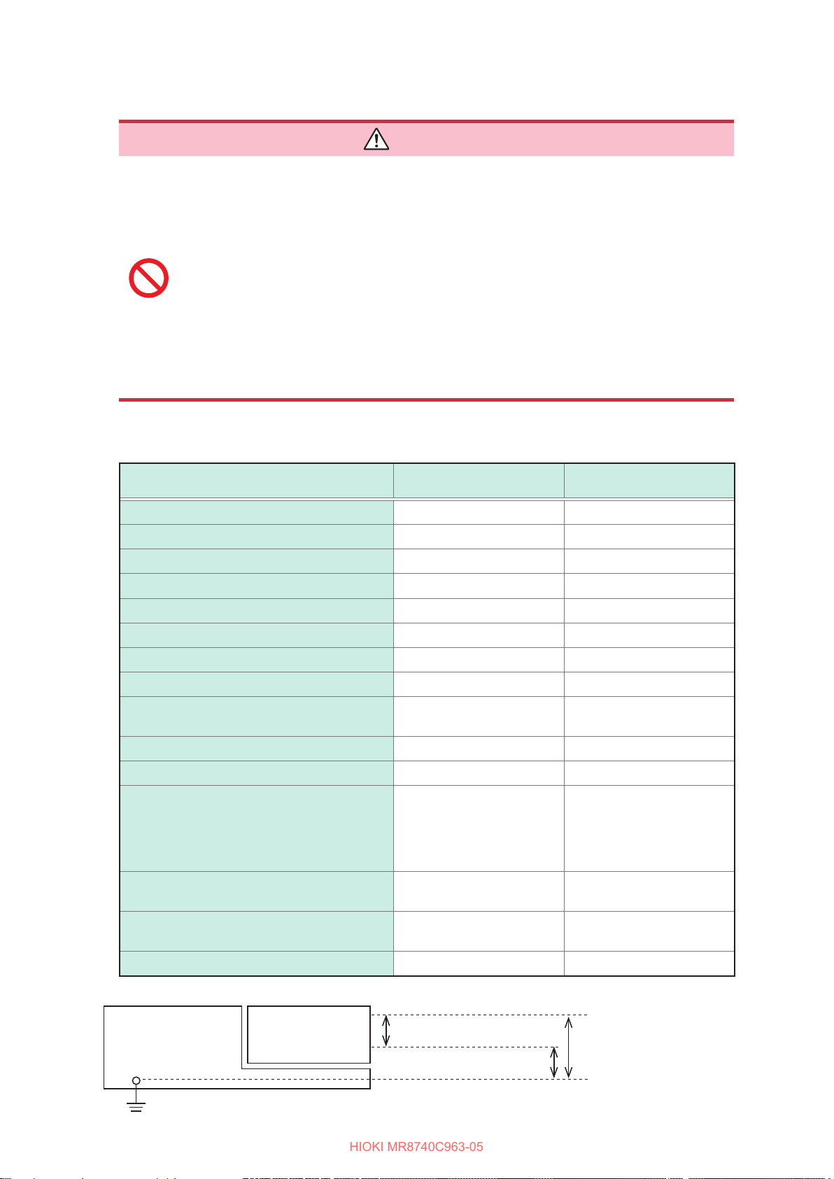
Measurement categories
To ensure safe operation of measuring instruments, IEC 61010 establishes safety standards
for various electrical environments, categorized as CAT II to CAT IV, and called measurement
categories.
DANGER
• Using a measuring instrument in an environment designated with a higher-
numbered category than that for which the instrument is rated could result in a
severe accident, and must be carefully avoided.
• Never use a measuring instrument that lacks category labeling in a CAT II to
CAT IV measurement environment. Doing so could result in a serious accident.
CAT II: When directly measuring the electrical outlet receptacles of the primary electrical
circuits in equipment connected to an AC electrical outlet by a power cord (portable
tools, household appliances, etc.).
CAT III: When measuring the primary electrical circuits of heavy equipment (xed installations)
connected directly to the distribution panel, and feeders from the distribution panel to
outlets.
CAT IV: When measuring the circuit from the service drop to the service entrance, and to the
power meter and primary overcurrent protection device (distribution panel).
Distribution Panel
Service Entrance
Service Drop
CAT IV
Power Meter
Fixed Installation
Internal Wiring
CAT III
CAT II
T
Outlet
The applicable measurement category is determined based on the module being used.
Refer to “Handling the instrument and modules” (p. 10).
7
Page 14

Operation Precautions
HIOKI MR8740C963-05
Operation Precautions
Follow these precautions to ensure safe operation and to obtain the full benets of the various
functions.
Checks before Use
DANGER
If the connection cords or the instrument is damaged, there is a risk of an electric
shock. Perform the following inspection before using the instrument:
• Check that the insulation of the connection cords are neither ripped nor torn
and that no metal parts are exposed before using the instrument. Using the
instrument under such conditions could result in an electric shock. Replace the
connection cords with those specied by our company.
• Check if there is any damage to the instrument occurred during storage or
shipping and verify that it operates normally before using the instrument. If you
nd any damage, contact your authorized Hioki distributor or reseller.
Installing the instrument and modules
Installing the instrument in inappropriate locations could cause a malfunction of
the instrument an accident, or re. Avoid the locations that are:
• Exposed to direct sunlight or high temperatures
• Exposed to corrosive or combustible gases
• Exposed to strong electromagnetic elds or electrostatic charges
• Near induction heating systems (such as high-frequency induction heating
systems and IH cooking equipment)
• Susceptible to vibration
• Exposed to water, oil, chemicals, or solvents
• Exposed to high humidity or condensation
• Exposed to high quantities of dust particles
• Unplugging the power cord kills power to the instrument. Be sure to provide
enough unobstructed space to unplug the power cord immediately in an
emergency.
• Use M4 × 8 mm screws to x the rack-mount brackets on the MR8740-50.
Using a screw longer than 8 mm can cause damage to the inside of the instrument
or an electric shock.
WARNING
8
Page 15

Operation Precautions
HIOKI MR8740C963-05
CAUTION
Failure to observe the following precaution may result in bodily injury.
• The instrument weighs about 14 kg (20.8 kg with modules installed in all slots). It
should be moved by at least two people.
• The instrument is heavy. When transporting it, follow your company’s workplace safety
standards to assure safety (for example, by wearing non-slip gloves and protective
footwear).
5 cm or wider
• Do not place the instrument on an unstable table.
• Do not place the instrument on an inclined
surface.
• Do not stack the multiple instruments.
• Vents must not be blocked.
• To prevent overheating, be sure to leave 5 cm
(2 inches) around the instrument.
• The instrument should be operated only with the
bottom side downwards.
9
Page 16
Operation Precautions
HIOKI MR8740C963-05
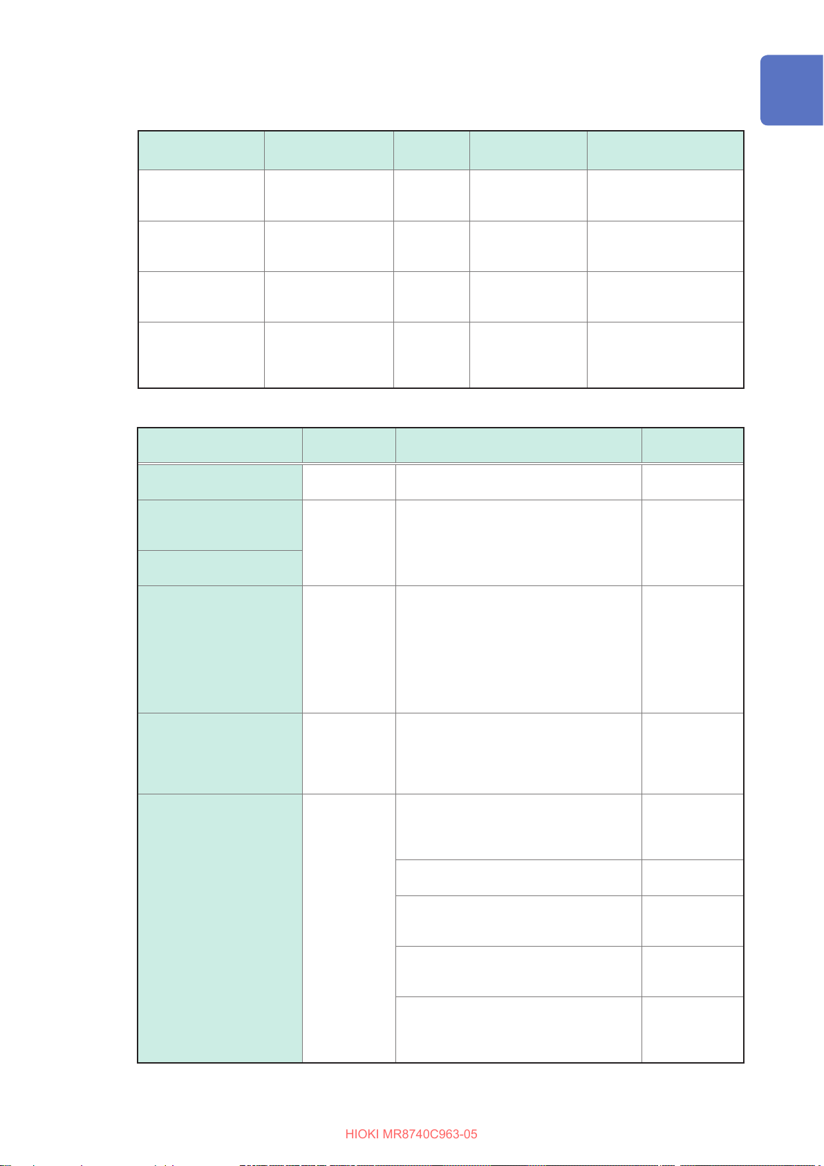
Handling the instrument and modules
• Do not use the modules or the cables to measure circuits that exceed those
ratings or specications. Damage to the instrument or overheating can cause
bodily injury.
• The maximum input voltage and maximum rated voltage to earth of the modules
and connection cords are shown in the following table. To avoid an electric
shock and damage to the instrument, ensure that input voltage never exceeds
these limits. The lower maximum input voltage of the module or connection
cord must be used. Measuring a voltage exceeding this value can cause
damage to the instrument, resulting in bodily injury. The same applies to the
maximum rated voltage to earth using an input attenuator for the measurement.
Ensure that the connection does not allow the input voltage to exceed the
maximum rated voltage to earth.
Refer to
Rating of input modules
“5.2 Specications of the Options” (p. 103).
DANGER
Modules Maximum input voltage
Model 8966 Analog Unit
Model 8967 Temp Unit – 300 V AC/DC (CAT II)
Model 8968 High Resolution Unit
Model U8969 Strain Unit – 30 V rms / 60 V DC
Model 8970 Freq Unit
Model 8971 Current Unit – Non-isolated
Model 8972 DC/RMS Unit
Model 8973 Logic Unit – Non-isolated
Model U8974 High Voltage Unit
Model U8975 4ch Analog Unit
Model U8977 3CH Current Unit – Non-isolated
Model U8978 4CH Analog Unit
400 V DC 300 V AC/DC (CAT II)
400 V DC 300 V AC/DC (CAT II)
400 V DC 300 V AC/DC (CAT II)
400 V DC 300 V AC/DC (CAT II)
1000 V DC
700 V AC
200 V DC 300 V AC/DC (CAT II)
40 V DC (Direct input)
400 V DC (with Model 9665
10:1 Probe used)
Maximum rated voltage to
earth
1000 V AC/DC (CAT III)
600 V AC/DC (CAT IV)
30 V AC, 60 V DC
(Direct input)
300 V AC/DC (CAT II)
(with Model 9665 10:1
Probe used)
10
Model U8979 Charge Unit
Model
MR8990
Model U8991 Digital Voltmeter Unit
Digital Voltmeter Unit
ModulesModel MR8740T
High
Low
40 V DC
500 V DC 300 V AC/DC (CAT II)
100 V DC 100 V AC/DC
Maximum input voltage
30 V AC
60 V DC
Maximum rated voltage
to earth
Page 17
Rating of generator modules
HIOKI MR8740C963-05
You can mixedly install generator modules and measurement modules in the instrument.
Operation Precautions
Intended use Model name Number of
For generating sine
wave and DC
For generating pulse
For generating
arbitrary waveforms
For generating DC
voltage, DC current,
and resistance
generation
Model MR8790
Waveform Generator
Unit
Model MR8791
Pulse Generator Unit
Model U8793
Arbitrary Waveform
Generator Unit
Model U8794
VIR Generator Unit
Ratings of connection cords
Connection Cord
Model L9197
Connection Cord
Model L9198
Connection Cord
(for measuring low-voltage)
Model L9217
Connection Cord
Model L9790
Connection Cord
Model 9322
Dierential Probe
Model L4940
Connection Cord
*: When Model U8974 High Voltage Unit is used
Maximum
input voltage
600 V AC/DC
300 V AC/DC
600 V AC/DC
2000 V DC
1000 V AC
1000 V DC*
Maximum output
channels
4 20 kHz −10 V to 10 V
8 20 kHz
2 100 kHz −10 V to 15 V
8
Maximum rated voltage to earth
600 V AC/DC (CAT III)
300 V AC/DC (CAT IV)
600 V AC/DC (CAT II)
300 V AC/DC (CAT III)
• With Model L9790-01 Alligator Clip or
Model 9790-03 Contact Pin attached
600 V AC/DC (CAT II)
300 V AC/DC (CAT III)
• With Model 9790-02 Grabber Clip
attached
300 V AC/DC (CAT II)
150 V AC/DC (CAT III)
• With grabber clips attached
1000 V AC/DC (CAT II)
• With alligator clips attached
1000 V AC/DC (CAT II)
600 V AC/DC (CAT III)
• With Model L4935 Alligator Clip Set or
Model L4932 Test Pin Set attached
600 V AC/DC (CAT IV)
1000 V AC/DC (CAT III, CAT II)
• With Model L9243 Grabber Clip attached
1000 V AC (CAT II)
• With Model L4936 Bus Bar Clip Set
attached
600 V AC/DC (CAT III)
• With Model L4937 Magnetic Adapter Set
attached
1000 V AC/DC (CAT III)
• With Model L4934 Small Alligator Clip
Set attached
300 V AC/DC (CAT III)
600 V AC/DC (CAT II)
frequency
Output voltage
TTL level
(amplitude: 0 to 5 V)
Open-collector output
Voltage: −0.1 V to 5.3 V
Current: −5 mA to 5 mA
Resistance: 10 Ω to 1 M
Maximum rated
1 A
0.2 A
1 A
10 A
1 A
5 A
2 A
3 A
Ω
current
–
11
Page 18

Operation Precautions
HIOKI MR8740C963-05
Connection Cord
Model P9000-01
Dierential Probe
Model P9000-02
Dierential Probe
Model 9166
Connection Cord
Model L9795-01
Connection Cable
(for generating)
Model L9795-02
Connection Cable
(for generating)
It is recommended to measure the secondary side of a distribution panel with
the U8974 High Voltage Unit. Do not measure the primary side of the distribution
panel because an unrestricted current ow could damage the instrument and
facilities if a short circuit occurs.
• Each channel of Model U8979 Charge Unit has the BNC terminal and miniature
connector terminal with the common ground. Do not connect cables with each
of the terminals simultaneously to avoid a short-circuit.
Maximum
input voltage
1000 V AC/DC 1000 V AC/DC (CAT III) –
30 V AC
60 V DC
±30 V 30 V rms AC, 42.4 V peak AC, or 60 V DC –
Maximum rated voltage to earth
For inputting voltage into Model U8979 –
Maximum rated
current
DANGER
WARNING
• To avoid an electric shock and damage to the module and the instrument,
conrm that the instrument is turned o and that the connection cords are
disconnected before removing or replacing a module.
• To avoid an electric shock, install a blank panel over any slot with a module
removed.
• To prevent the instrument damage or an electric shock, use only the screws that
are originally installed for securing the module in place. If you have lost any
screws or nd that any screws are damaged, please contact your authorized
Hioki distributor or reseller.
12
Page 19
Operation Precautions
HIOKI MR8740C963-05
CAUTION
• Do not touch module connectors inserted to the instrument to avoid damaging a
module.
• To avoid damage to the instrument, do not unplug the power cable from the
instrument when operations are in progress. Be sure to use the power key to turn o
the instrument.
• The U8794 permits a load resistance of 1 kΩ or more while outputting a voltage. Do
not connect a load resistance lower than the permissible value or short-circuit an
output terminal. Damage to the instrument could result.
• Do not set the OUTPUT terminal status of the U8794 to SHORT when a power supply
unit connects with the OUTPUT terminal. A short-circuit current will ow, resulting in
damage to the instrument or power supply device.
• Do not connect anything with the U8794 OUTPUT terminal during a general test
of the self-diagnosis function and an oset measurement of the oset canceling
function. When the connected target is a power supply device, the instrument and the
connected target can be damaged because the OUTPUT terminals of each channel
are momently short-circuited.
• The mounting screws must be rmly tightened or the module may not work as
specied, or may even fail.
• When you use the U8794 resistance generation function to presume a characteristic
of a connected target with an output resistance of less than 1 kΩ, a current that
exceeds the specication will ow, resulting in damage to the instrument and the
connected target.
• Model U8979 Charge Unit has two miniature connectors with the maximum input
charge of ±500 pC (for six higher-sensitivity range) or ±50,000 pC (for six lowersensitivity range). Inputting a charge that exceeds these value causes damage to the
instrument.
• Use an acceleration sensor with a built-in pre-amplier that conforms to the
specication of Model U8979 (3.5 mA, 22 V). Using a inapplicable sensor may cause
damaging itself.
IMPORTANT
• Install a blank panel over the slot with no module installed. If the measurement is performed
without the blank panel installed, the instrument may not work as specied because of
temperature instability within the modules.
• If any unexpected waveform is observed or a module is not recognized, send the instrument for
repair.
• Disconnect all cables and remove a USB ash drive before carrying the instrument.
• Waveforms can frequently uctuate even when no voltage is applied due to an induction voltage.
This, however, is not a malfunction.
• This instrument may cause interference if used in residential areas. Such use must be avoided
unless the user takes special measures to reduce electromagnetic emissions to prevent
interference to the reception of radio and television broadcasts.
Precautions during shipment
To avoid damage to the instrument, protect it from physical shock when transporting
and handling. Be especially careful to avoid physical shock due to dropping it.
• Store the packaging materials even after unpacking, because you will need them when you
transport the instrument.
CAUTION
13
Page 20

Operation Precautions
HIOKI MR8740C963-05
• To ensure safe handling, when transporting the instrument, please use the original box and
packing materials,
but do not use if the box is damaged or warped, or if the packing materials are in poor condition
or incomplete.
If you nd any damage, contact your authorized Hioki distributor or reseller.
• When packing the instrument, make sure to disconnect the test leads and power supply cords
from the main device.
• When transporting, avoid dropping or other excessive impact.
CD precautions
• Exercise care to keep the recorded side of discs free of dirt and scratches. When writing text on a
disc’s label, use a pen or marker with a soft tip.
• Keep discs inside a protective case and do not expose to direct sunlight, high temperature, or
high humidity.
• Hioki is not liable for any issues your computer system experiences in the course of using this
disc.
14
Page 21

Handling storage devices
HIOKI MR8740C963-05
• Do not carry the instrument with a USB ash drive inserted. Damage could result.
•
Do not subject the instrument to extreme shock or vibration. Shock can cause damage to
the built-in SSD unit.
• Do not insert a storage device upside down, backward, or in the wrong direction.
Doing so may damage the storage device or instrument.
Exercise care when using such products because static electricity could damage the
external storage device or cause a malfunction of the instrument.
IMPORTANT
• Do not extract any external storage device or turn o the instrument while the instrument is
accessing the storage device (while the green DIAG LED is lighting up). Data stored in the
device could be lost.
• No compensation is available for loss of data stored on the external storage device (USB ash
drive) or the built-in SSD unit of the instrument, regardless of the content or cause of damage
or loss. Be sure to back up any important data stored on the device (USB ash drive) and the
built-in SSD unit of the instrument.
• When the instrument is left powered o for a long period of time (about 1 year or more), the
data saved to the built-in SSD may be lost. Be sure to back up the data if the instrument is to
be left powered o for a long time.
Operation Precautions
CAUTION
• With some external storage device, the instrument may not start up if power is turned on while
the device is inserted. In such a case, turn o and cycle the instrument.
• The instrument supports not all commercially available USB ash drives.
• The number of times data can be written on external storage devices (USB ash drive) and the
built-in SSD unit of the instrument is limited by their ash memory. If data has been rewritten
many times, data reading and writing capabilities will be degraded. In that case, replace the
device.
• Model Z4006 USB Drive can be used to save data. Use the product available as Hioki’s option
only. (p. 5)
15
Page 22
Operation Precautions
HIOKI MR8740C963-05
Built-in battery
The instrument contains a battery (sealed lead acid battery) to shut down Windows® in case power
is cut (power outrage or turning o a breaker). Since the battery has a limited life expectancy,
it must regularly be replaced. When replacing batteries, please contact your authorized Hioki
distributor or reseller.
Expected lifetime: About 2 years (Operated at an ambient temperature of
25°, when the instrument is turned o once a day)
About 4 years (Operated at an ambient temperature of
25°, when the instrument is turned o ve times a year)
CAUTION
• You have to charge the battery periodically even if you do not use the instrument.
Periodically charge the battery every three months at a storage temperature of 35°C;
every six months at a storage temperature of 25°C. Failure to do so may reduce the
battery life expectancy.
• Do not install the instrument in a sealed space or near a re. Doing so may cause an
explosion or re.
• Do not use the instrument at high ambient temperature. Do not use the instrument
with the end-of-life battery. Doing so may cause electrolyte leakage, resulting in a bad
inuence that includes a re at a worst. Make sure that you use the instrument within
the operating temperature range and inspect and replace the battery periodically.
16
Page 23
Operation Precautions
HIOKI MR8740C963-05
Before connecting cords
For detailed precautions and instructions on connections, refer to the instruction manuals of your
connection cords.
DANGER
• If the insulation on a connecting cable melts, the metal conductor may be
exposed. Do not use any cable whose metal conductor is exposed. Doing so
could result in an electric shock, burn, or other hazards.
When measuring power line voltage
• Only connect connection cords on the secondary side of a distribution panel. If
a short-circuit occurs on the secondary side of the distribution panel, the panel
will interrupt the short-circuit current. Do not connect the connection cords on
the primary side of the distribution panel because an unrestricted current ow
can damage the connection cords and facilities if a short-circuit occurs.
• To prevent an electrical shock and bodily injury, do not touch any input
terminals on the VT (PT), CT or the instrument when they are in operation.
• Do not leave the measurement cables connected to the instrument in an
environment where voltage may surge beyond the maximum input voltage.
Applying voltage may result in damage to the instrument, or serious accidents.
• Do not cause a short-circuit between another wire and the wire to be measured
with the metal tip of the connection cord. Arcs or such grave accidents are
likely to occur.
• To avoid a short-circuit or electric shock, do not touch the metal tip of the
connection cord.
WARNING
• To prevent an electric shock, conrm that the white or red portion (insulation
layer) inside the cable is not exposed. If a color inside the cable is exposed, do
not use the cable.
• Do not place a cable in contact with the lines to be measured. Any contact
can cause the instrument to malfunction and lead to a short-circuit or electric
shock, resulting in bodily injury.
• Be sure to connect the voltage input and current input terminals correctly.
incorrect connection could damage or a short-circuit.
• Use only the specied connection cords. Using a non-specied cable may
result in unsafe measurements. Using a non-specied cable may also result in
incorrect measurements due to poor connection or other reasons.
• To avoid electric shock, do not exceed the lower of the ratings shown on the
modules and connection cords.
An
17
Page 24
Operation Precautions
HIOKI MR8740C963-05
• To prevent cord damage, do not step on cords or pinch them between other objects.
• The cable is hardened in freezing temperatures. Do not bend or pull it to avoid tearing
• Do not use any cable terminated with a metal BNC connector for connecting cables
CAUTION
Do not bend or pull on cords at their base.
its shield or cutting the cable.
to the BNC jacks on modules. If you connect a metal BNC cable to insulated BNC
connector, the insulated BNC connector and instrument may be damaged.
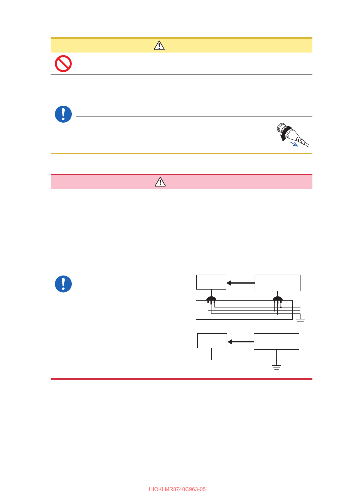
• To prevent damage to the BNC connector, be sure to release the
locking mechanism, grip the head of the connector (not the cord),
and pull it out.
Before connecting a logic probe to a measuring object
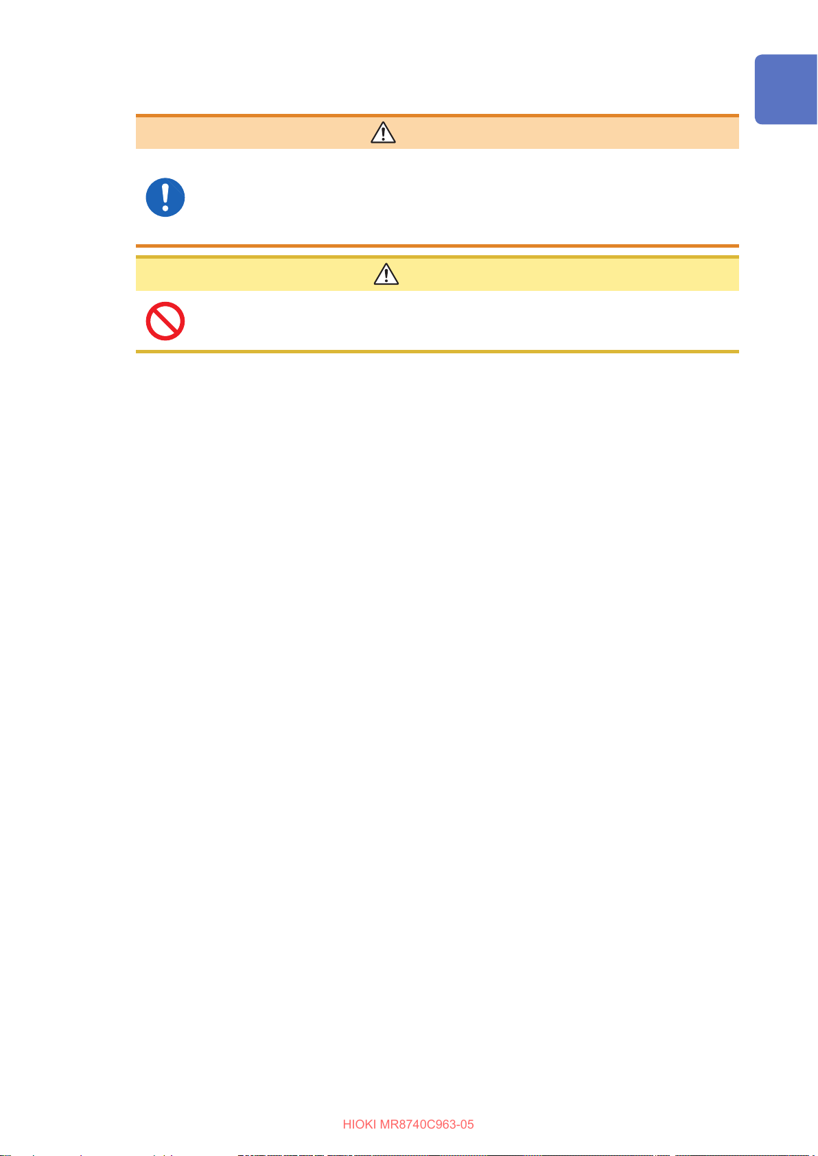
DANGER
To avoid an electric shock, a short-circuit and damage to the instrument, supply
power from a single main to the instrument and a measuring object with the
accompanying power cord.
The ground pin of logic terminal of Model 9320-01 Logic Probe (or Model 9327
Logic Probe) is not isolated from the instrument ground. The ground is shared.
If each of the terminals are supplied with power from separate mains or power
is supplied through a non-grounded power cord, the measuring object and the
instrument may be damaged because a current may ow through the logic probe
due to the resulting ground potential dierence between the terminals. The
following connection procedure is recommended to avoid this problem:
• Connect the power cord provided
to the instrument and supply
power from the same outlet as the
measuring object.
• Connect the ground of the
measuring object to the GND
terminal (functional earth terminal)
of the instrument.
(Always supply power from a single
main.)
Refer to “2.6 Supplying Power to
the Instrument” (p. 63).
Measuring
object
Measuring
object
GND
1
2
Model MR8740T
Logic
Probe
Model MR8740T
Logic
probe
18
Functional ground terminal
Page 25
Before turning on the instrument
HIOKI MR8740C963-05
• To prevent electrical shock and to maintain the safety specications of this
instrument, connect the accompanying power cord only to an inlet.
• Before turning the instrument on, make sure the supply voltage matches that
indicated on its power connector. Connection to an improper supply voltage
may damage the instrument and present an electrical hazard.
Do not operate the instrument on any of the power sources (UPS or uninterruptible
power supply, DC/AC inverter) that provide rectangular-wave or pseudo-sine-wave
power. Doing so may damage the instrument.
Operation Precautions
WARNING
CAUTION
19
Page 26
Operation Precautions
HIOKI MR8740C963-05
Before connecting the instrument to external equipment
DANGER
To avoid electrical hazards and damage to the instrument, do not apply voltage
exceeding the rated maximum to the external control terminals.
Model MR8740T
I/O terminal Maximum input voltage
IN1
IN2 10 V DC
OUT1 50 V DC, 50 mA, 200 mW
OUT2 50 V DC, 50 mA, 200 mW
TRIG.OUT 50 V DC, 50 mA, 200 mW
Model U8793 Arbitrary Waveform Generator Unit
I/O terminal Maximum input voltage
IN −0.5 V to 7 V DC
OUT 30 V DC, 50 mA
10 V DC
WARNING
To avoid an electric shock or damage to the equipment, always observe the
following precautions when connecting your external equipment to external
control terminals.
• Always turn o the instrument and any equipment to be connected before
making connections.
• Be careful to avoid exceeding the ratings of the external control terminals.
• The external control terminal shares the ground with the chassis. As required,
isolate the devices and systems to be connected to the external control
terminals from one another.
Always turn both devices o before connecting and disconnecting an interface
connector. This may cause an electric shock.
I/O terminals Maximum input voltage
EXT.TRIG
EXT.SMPL 10 V DC
10 V DC
20
CAUTION
• Use a common ground to both the instrument and the connected equipment. Using
dierent ground circuits will result in a ground potential dierence between the
instrument and the connected equipment. If the cable is connected while such a
potential dierence exists, it may result in equipment malfunction or failure.
• Before connecting or disconnecting any cable, always turn o the instrument and your
device to be connected. Failure to do so could result in an equipment malfunction or
damage to the equipment.
• After inserting the connector, securely tighten the screws of the connector. Failure to
do so could result in an equipment malfunction or damage to the equipment.
• To prevent damage to the equipment, use the recommended type of wires to connect
your external equipment to the external control terminal, or otherwise ensure that the
wires have sucient withstand voltage and current capacity.
Refer to “2.3 Connecting the External Control Terminals” (p. 56).
Page 27
How to Refer to This Document
HIOKI MR8740C963-05
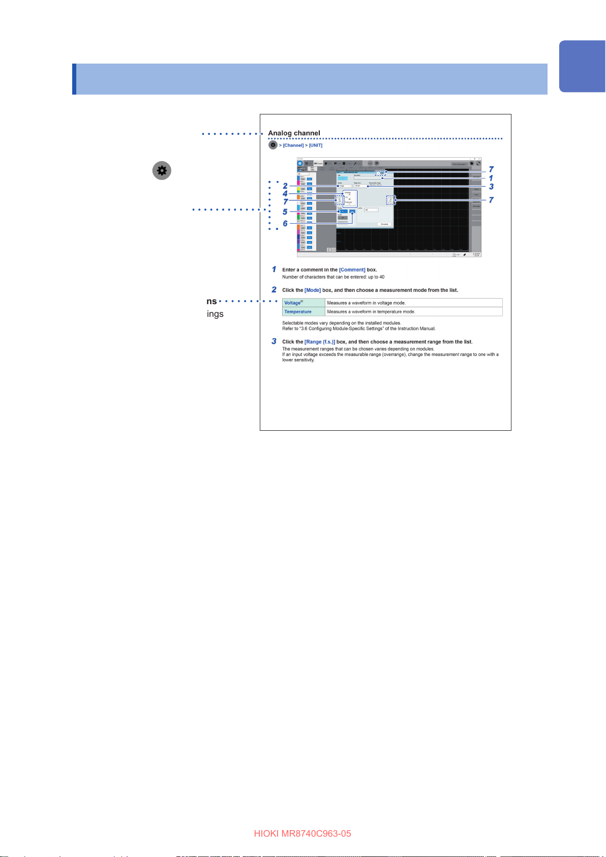
How to open a screen
Indicates the order of clicking the
screens.
The button
setting key.
Procedure numbers
Numbered same as a
corresponding step-by-step
instruction.
Options and explanations
Describes selectable settings
when an item is clicked.
The icon indicates the default
setting of the item.
represents the
How to Refer to This Document
21
Page 28

How to Refer to This Document
HIOKI MR8740C963-05
22
Page 29
1
HIOKI MR8740C963-05
Overview
1.1 Product Overview and Features
This recorder allows you to observe a wide range of waveforms from low-speed signals to highspeed waveforms.
You can mainly use this instrument for analyzing test and evaluation results of various products and
troubleshooting those products.
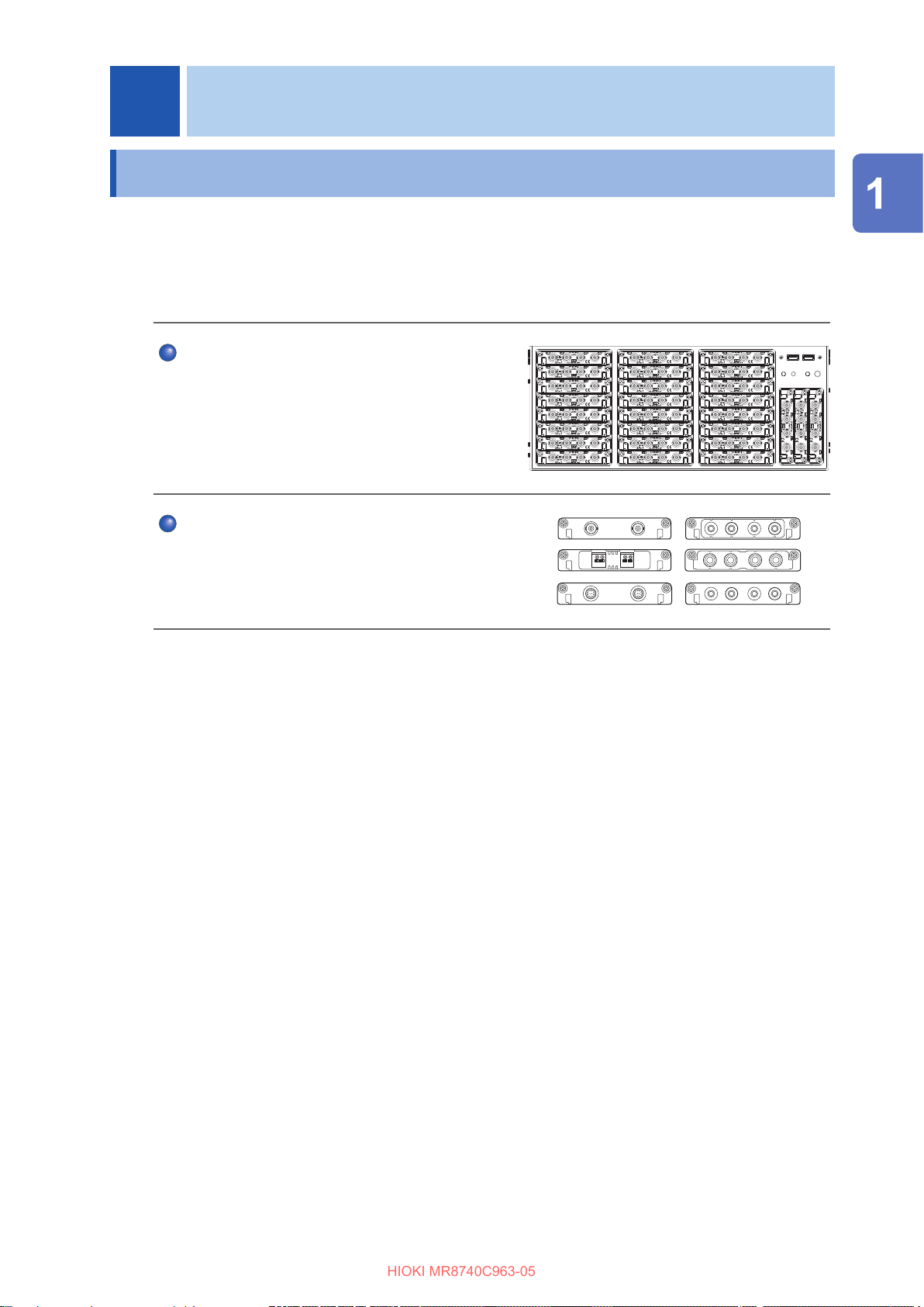
Multichannel simultaneous sampling
This instrument can simultaneously measure signals
across up to 108 channels.
Extensive line of measurement modules
Many types of measurement modules let the
instrument measure a variety of signals that include
voltage, current, temperature, and frequency.
Overview
23
Page 30

Name and Function of Each Part
HIOKI MR8740C963-05
1.2 Name and Function of Each Part
Front side
1
No. Name Function
Up to 27 modules can be installed in the instrument.
You can install as many modules of Model 8971 Current
Unit and Model U8977 3CH Current Unit as possible in any
Module embedding part
1
slots unless the total number of connectable current sensors
reaches nine. Model 8973 Logic Unit can be installed in slots
to which UNIT 25, UNIT 26, or UNIT 27 is assigned only.
Refer to an instruction manual that comes with each input
module.
2
3
4
5
6
Reference
page
p. 10
p. 36
USB2.0 connector Connect a USB ash drive, USB mouse, or USB keyboard.
2
Start button. Activates the instrument or puts it into standby when pressed.
3
POWER lamp
4
DIAG lamp Indicates instrument status.
5
Command error lamp Lights up if a command error occurs.
6
Indicates whether the instrument is powered on or in standby
mode.
p. 60
p. 26
24
Page 31

Rear side
HIOKI MR8740C963-05
Name and Function of Each Part
5
1
4
Overview
6
No. Name Function
Vents (fan motors) Do not block the vents. –
1
Windows® license The Windows
2
The rst four digits of the 9-digit number indicate the year (the
rst two digits omitted) and the month of manufacture. Do not
Serial number
3
Main power switch Turns the instrument on and o. –
4
Power inlet Connects the power cord provided.
5
Interface terminals Connect an LCD, LAN cable, and USB cable.
6
External control
7
terminals
remove this sticker as the number is important.
Inform your authorized Hioki distributor or reseller of this
number if required.
Connect an external device.
7
®
license label is axed. –
2
3
CAUTION
Reference
page
–
p. 19
p. 63
p. 27
p. 56
If you set the main power switch to o while the instrument is powered on, the power
from the built-in battery is lost, resulting in incorrect Windows® shutdown. Be sure to use
the front start button to set the instrument in the standby state, and then set the main
power switch to o.
25
Page 32

Name and Function of Each Part
HIOKI MR8740C963-05
Instrument status indicator
The LEDs indicate the instrument status.
Basic LED indicator
LED name Color Lighting up /
blinking
POWER
STANDBY
DIAG Refer to the
CMD ERR Red Lighting up A command received contained a
Orange Lighting up Stand-by status Set the rear switch
Green Lighting up Power-on status Shut the power o.
Green Blinking Power-on status (warm-up) Shut the power o.
table below.
Refer to the
table below.
Refer to the table below.
syntax error.
When lights up How to turn o
Details of DIAG LED
DIAG LED mode table
Indicator
priority order
1 The inside temperature is high
(ambient temperature > 35°C).
2 The inside temperature is low
(ambient temperature < 10°C).
Status Color Note
Red
Purple
the LED
to o.
–
Send the
command to turn
o the LED.
–
–
*CLS
3 CPU load rate ≥ 80% Yellow Updated every 0.5 seconds, based
on average load rates calculated
over the period.
4 Waiting for a trigger. Blue –
4 The recording is in progress. Green –
4 The recording is complete. Pink Switches to the normal operation
indication when a new command is
received.
5 During normal operation (under
suspension)
White
–
26
Page 33

Name and Function of Each Part
HIOKI MR8740C963-05
1
6
No. Name Function
PS2 connector Not available –
1
COM terminal Not available –
2
VGA terminal
3
4
1000BASE-T connector
LINK ACT
5
2
7 8
Connect a display with an RGB cable.
Maximum resolution: 2560 × 1600
Attach a LAN cable to connect the instrument to your
network.
ACT LED
Blinking: Communicating data
LINK LED
Yellow light: 1000BASE
Green light: 100BASE
O: 10BASE
3
4
9
5
Overview
10
Reference
page
–
p. 58
USB2.0 connector
6
HDMI terminal
7
DisplayPort* terminal
8
USB3.0 connector
9
Audio terminal Not available –
10
• A resolution of 1920 × 1080 dots or more is recommended. Using a display with a lower
resolution can cause poor visibility of waveforms.
• Using a 4K-resolution monitor connected to the HDMI or DisplayPort terminal with the
maximum resolution set may require longer time for processing command communication and
displaying screens.
*: Trademark of another company
Connect a USB ash drive, USB mouse, or USB
keyboard.
Connect a display with an HDMI cable.
Maximum resolution: 3840 × 2160
Connect a display with a DisplayPort cable.
Maximum resolution: 4096 × 2160
Connect a USB ash drive, USB mouse, or USB
keyboard.
p. 60
–
–
p. 60
27
Page 34

Screen
HIOKI MR8740C963-05
1.3 Screen
A commercially-available monitor is required to display information. Use a monitor that supports a VGA
input, HDMI input, or DisplayPort input. (Full HD with a resolution of 1920 × 1080 dots is recommended)
Screen conguration
Waveform screen (p. 29)
List screen
Setting screen
Status
This screen is used to set the measurement conditions such as the sampling rate,
recording length (shot), and saving data.
Refer to
Channel
This screen is used to congure the input channel settings such as the measurement
range and low-pass lter.
Refer to
Sheet screen
This screen is used to congure a display settings for each sheet.
Choose channels to be displayed on each sheet.
Refer to “1.4 Conguring the Sheet Settings” of the Instruction Manual.
Trigger
This screen is used to congure the trigger settings.
Refer to
Calculation screen
This screen is used to congure the numerical and waveform calculation settings.
Refer to “7 Numerical Calculation Functions” and “8 Waveform Calculation”in Instruction
Manual.
“3.2 Setting Measurement Conditions” (p. 70).
“3.3 Conguring the Input Channel Settings” (p. 72).
“3.4 Conguring the Level Trigger Settings” (p. 75).
28
System screen
This screen is used to congure the system environment, communications, and external
control terminal settings, and to initialize the instrument. You can also check the
instrument conguration on this screen.
Refer to
“6.2 Initializing the Instrument” (p. 153).
Page 35

Explanation of each screen
HIOKI MR8740C963-05
Screen
Waveform screen
2
43 5 6 7
8 9
1
10
1213
14
No. Item Description Reference page
1
Switches between the setting and waveform screens. p. 70, p. 83
11
Overview
Measurement condition
2
setting
Sheet selection Switches among preset sheets. *
3
Search setting screen Allows you to set search conditions. *
4
5
6
7
8
9
10
11
12
13
14
(Start icon)
(Stop icon)
(Save icon)
File screen Opens the le screen. *
Waveform area zoom-in Zooms in the waveform area. –
Function buttons
Current date and time Displays the current date and time.
Eject button Ejects a USB ash drive.
Trigger time Displays the trigger time. –
Number of measurement
times
Allows you to choose a sampling rate, recording length
(the number of points and user-dened length), and
recording mode (single or repeat).
Starts a measurement.
Stops the measurement.
Saves data.
Allows you to choose functions available on the
waveform screen.
Displays the processing state of the instrument.
Displays the number of measurement times.
p. 70
1
2
p. 77
3
p. 83
p. 65
p. 61
–
*1: Refer to “1.4 Specifying the Sheet Settings” of Instruction Manual.
*2: Refer to “6 Search Function” of Instruction Manual.
*3: Refer to “4 Saving/Loading Data and Managing Files” of Instruction Manual.
29
Page 36

Screen
HIOKI MR8740C963-05
Cross-screen functions
1
2
No. Name Description
Menu tab Click a tab to choose a menu to open.
1
Sub-menu tab Click a tab to choose a sub-menu to open.
2
30
Page 37

1.4 Basic Operation
HIOKI MR8740C963-05
Mouse operation
Basic Operation
Using a commercially available USB mouse enables you to operate the instrument.
Basic mouse operation for the instrument is as follows:
Mouse operation Description
Click Allows you to choose a menu or execute an action.
Wheel button Changes options to be selected.
Up/down/left/right Moves the mouse cursor around.
External noise may cause the mouse to malfunction. Keep the mouse and mouse cable as far away
as possible from sources of noise.
Use the mouse on an insulated table. Some commercially available mouse devices are susceptible
to noise and using such a mouse on a metal table may cause the instrument to malfunction.
Overview
31
Page 38

Basic Operation
HIOKI MR8740C963-05
Changing screens and settings
Switching between the waveform and setting screens
Click the button to switch between the waveform and setting screens.
Waveform screen
Switching the setting screens
Click a tab to switch the setting screens.
Setting screen
32
Page 39

Choosing an option from a list
HIOKI MR8740C963-05
Example: Choosing a sampling rate Example: Choosing a measurement range of Model
Entering numerical values
Example: Entering a user-dened recording length Example: Entering a scaling ratio
Basic Operation
8966
Overview
33
Page 40

Basic Operation
HIOKI MR8740C963-05
Help Function (Displaying Instruction Manual)
The HTML le of a selected manual appears.
> [Func] > [Help]
34
Page 41

2
HIOKI MR8740C963-05
Preparing for Measurement
Carefully read “Operation Precautions” (p. 8) before starting preparation.
Keyboard, mouse
(p. 31)
External control
terminals
(p. 56)
Zero-adjustment
(p. 66)
Modules
(p. 36)
Computer
(p. 58, p. 86)
Setting the clock
(p. 65)
Connection cords
Preparing for Measurement
(p. 38)
Storage devices
(p. 60)
Power cord
(p. 63)
35
Page 42

Installing and Removing Modules
HIOKI MR8740C963-05
2.1 Installing and Removing Modules
If you order the instrument with modules specied, the instrument will be delivered with the modules
pre-installed. Follow the procedures below to install a module additionally, replace modules, or
remove a module. Up to four modules of Model 8971 Current Unit and up to three modules of
Model 8973 Logic Unit can be installed to the instrument.
Refer to “Handling the instrument and modules” (p. 10).
Required items: Phillips-head screwdriver (No. 2)
How to install a module
Orient and insert the module all the way into the
1
instrument.
Tighten the two screws with the Phillips-head
Right side
2
screwdriver to secure the module.
How to remove the module
Knob
When not installing any module after removal
Install a blank panel. To order additional blank panels, contact your authorized Hioki distributor or
reseller.
Blank panel
Loosen the two module mounting screws with the
1
Phillips-head screwdriver.
Pinch the two knobs and pull out the module.
2
Place a blank panel.
1
Tighten the two screws with the Phillips screwdriver
2
to secure the blank panel.
36
Page 43

Allocation of modules and channels
HIOKI MR8740C963-05
Module numbers
Modules are numbered beginning at the top.
Installing and Removing Modules
Channel numbers
The channels are numbered
beginning from the top left.
Units 1 through 8
Units 9 through 16 Units 17 through 24
Units 25 through 27 (L to R)
Model 8973 Logic Unit can be installed in slots to which Unit 25, 26, or 27 is assigned only.
You can nd out information about the modules installed in the instrument in
Refer to
“System conguration check” (p. 164).
[System information].
Preparing for Measurement
> [System] > [System information]
37
Page 44

Attaching Connection Cords
HIOKI MR8740C963-05
2.2 Attaching Connection Cords
Refer to the manuals of the modules and connection cables if provided.
Measurement Applicable module Cable to be connected
Voltage
Frequency
Rotation
speed
Count
Temperature
Vibration
Load
Pressure
Acceleration
Torque
Displacement
Model 8966 Analog Unit
Model 8968 High Resolution Unit
Model 8972 DC/RMS Unit
Model U8975 4ch Analog Unit
Model U8978 4CH Analog Unit
Model U8979 Charge Unit*
Model 8970 Freq Unit
Model 8967 Temp Unit Thermocouple p. 42
Model U8969 Strain Unit Strain gauge transducer p. 43
Model U8979 Charge Unit Acceleration sensor p. 49
Model L9197 Connection Cord
Model L9198 Connection Cord
(For measuring low-voltage)
Model L9217 Connection Cord
Model L9790 Connection Cord
Model 9665 10:1 Probe
Model 9666 100:1 Probe
Model 9322 Dierential Probe
Model P9000-01 Dierential Probe
Model P9000-02 Dierential Probe
Model 9166 Connection Cord*
(For inputting voltage
into Model U8979)
Reference
page
p. 18
p. 40
Model 8971 Current Unit
Current
Logic signal
Voltage
(precision)
High voltage
Model U8977 3CH Current Unit
(Up to nine current sensors)
Model 8973 Logic Unit
(Up to 3 modules)
Model MR8990 Digital Voltmeter Unit Model L2200 Test Lead p. 51
Model U8991 Digital Voltmeter Unit
Model U8974 High Voltage Unit
Current sensor
Model 9320-01 Logic Probe
Model MR9321-01 Logic Probe
Model 9327 Logic Probe
Model L9197 Connection Cord
Model L9198 Connection Cord
(for measuring low-voltage)
Model L9217 Connection Cord
Model L9790 Connection Cord
Model L4940 Connection Cable
Set
*: Model 9166 Connection Cord can be used for Model U8979 Charge Unit only.
p. 45
p. 51
p. 40
p. 55
38
Page 45

Attaching Connection Cords
HIOKI MR8740C963-05
Output Applicable module Cable to be connected
Waveform
Pulse
DC voltage
DC current
Resistance
(simulated)
Model MR8790 Waveform Generator
Unit
Model U8793 Arbitrary Waveform
Generator Unit
Model MR8791 Pulse Generator Unit
Model U8794 VIR Generator Unit
Model L9795-01 Connection
Cable
Model L9795-02 Connection
Cable
Commercially available cable
(Half-pitch 50 pins)
Commercially available cable
(D-sub 25 pins)
Reference
page
p. 52
p. 53
p. 54
Preparing for Measurement
39
Page 46

Attaching Connection Cords
HIOKI MR8740C963-05
Connection cables (For measuring voltage, frequency, or rotation speed, and obtaining accumulations)
Insert connection cords to modules. Choose an appropriate connection cord based on the
maximum input voltage and tips of cables.
The maximum input voltage of the instrument or connection cord, whichever is lower, is applicable.
Refer to “Before connecting cords” (p. 17).
Required items: Connection cords
Connection cord
Model L9197 Connection Cord
Model L9198 Connection Cord
Model L9217 Connection Cord
Model L9790 Connection Cord
Example: with the alligator clip attached.
Maximum input
voltage
600 V Large alligator clip
300 V Small alligator clip
300 V BNC output
600 V Alligator clip
Grabber clip
Contact pin
Type
When the voltage to be measured exceeds the maximum input rating of the module
being used
(excluding Model U8991 Digital Voltmeter Unit)
Model 9665 10:1 Probe*
Model 9666 100:1 Probe*
Model 9322 Dierential Probe*
Model P9000-01 Dierential Probe*
Model P9000-02 Dierential Probe*
*1: The maximum rated voltage to earth depends on a module to be used.
*2: An optional power cord or AC adapter is required.
*3: An optional AC adapter or a commercially available USB cable is required.
1
1
2
3
3
Example: Model P9000-02 Dierential Probe
Alligator clip
40
Page 47

How to connect a cord
HIOKI MR8740C963-05
Attaching Connection Cords
Example: Model 8966 Analog Unit
1
Locking studs of
module connector
Locking studs
BNC connector slots
2
3
Lock
Align the slots in the BNC connector of a
1
connection cord with the locking studs of a
BNC connector on the module, and insert the
connector.
Turn the BNC connector of the connection cord
2
clockwise until it locks.
Connect the connection cord clips to a
3
measuring object.
How to disconnect the cord
Turn the BNC male connector of the connection cable
counterclockwise, and then pull out the connector.
Preparing for Measurement
41
Page 48

Attaching Connection Cords
HIOKI MR8740C963-05
Thermocouple (Temperature)
Connect thermocouples to Model 8967 Temp Unit.
Required items: Thermocouple and at-blade screwdriver (2.6-mm-width blade)
25 mm
Outer
insulation
Inner insulation
10 mm
Thermocouple
element wires
How to connect the thermocouple
Model 8967 Temp Unit
2
Thermocouple
4
1
3
Recommended cable
Compatible wire: Thermocouple element wires with a diameter
of 0.4 mm to 1.2 mm
Standard insulation stripping length: About 10 mm
Strip the insulation of the thermocouple wires as shown on the
left.
Depress a button on the terminal block on the
1
module with the at-blade screwdriver.
While depressing the button with the at-blade
2
screwdriver, insert each thermocouple wire into
the appropriate terminal hole
Release the button.
3
The thermocouple is connected.
Attach the thermocouple on a measuring
4
object.
How to disconnect the thermocouple
While depressing the button, pull the thermocouple wire.
• If noise inuences surrounding equipment, pass the thermocouple element
wires through the center hole of the ferrite clamp-on choke (comes with
Model 8967 Temp Unit) several times successively from the same end.
• If a thermocouple three meters long or longer is connected, the measurement
may be inuenced by the EMC environment that includes external noise.
• For K type and E type thermocouples, the physical phenomenon, short-range ordering can
probably cause incorrect temperature measurement in the range of 250°C to 600°C. Contact a
thermocouple manufacturer to choose proper thermocouples.
42
Page 49

Attaching Connection Cords
HIOKI MR8740C963-05
Strain gauge transducer
Connect a strain gauge transducer*1 to Model U8969 Strain Unit via Model L9769 Conversion
Cable*2.
*1: Hioki does not oer any strain gauge transducers.
*2: Model L9769 Conversion Cable is an accessory of Model U8969 Strain Unit.
CAUTION
To prevent damage due to in a break in a conversion cable, do not excessively bend,
pull, or twist the cables and joints between the cables and connectors.
Required items: Strain gauge transducer and Model L9769 Conversion Cable
How to connect the transducer
Preparing for Measurement
Model U8969 Strain Unit
1 2
Model L9769 Conversion Cable
Slot of the plug
Indentation of
the connector
Align the plug slot of Model L9769
1
with the outward indentation of Model
U8969, and then insert the plug into the
connector on Model U8969.
Insert the plug until it locks.
2
Connect Model L9769 to the strain gauge
3
transducer.
Connect the strain gauge transducer to a
4
measuring object.
How to disconnect the conversion cable
Gently pull the collar of the plug, which releases
the lock, and disconnect the cable.
43
Page 50

Attaching Connection Cords
HIOKI MR8740C963-05
Connector pin-out
Model U8969 Strain Unit
The metal shell is connected to the GND terminal of
the instrument.
Pin mark Description
A BRIDGE+
B INPUT−
C BRIDGE−
D INPUT+
E FLOATING COMMON
F SENSE+
G SENSE−
Model L9769 Conversion Cable
(Strain gauge converter)
Applied voltage:
A bridge voltage of 2 V
The metal shell is connected to the GND terminal of
the instrument.
Pin mark Description
A BRIDGE+, SENSE+
B INPUT−
C BRIDGE−, SENSE−
D INPUT+
E FLOATING COMMON
F N.C.
G N.C.
H N.C.
J N.C.
Model L9769 connection
• Pin F of the conversion cable (module end) is connected to pin A of the conversion cable
(transducer end).
• Pin G of the conversion cable (module end) is connected with pin C of the conversion cable
(transducer end).
IMPORTANT
• A bridge box is required to measure strain using a strain gauge. Use a commercially available
strain gauge and a bridge box.
• Some bridge boxes may be susceptible to noise. In that case, grounding the bridge box allows
the box to be less susceptible to noise. For information on how to ground the bridge box, refer
to the manual of your bridge box or contact its manufacturer.
You can use your Model 8969 Strain Unit with the instrument. The instrument with Model 8969
Strain Unit installed refers to Model 8969 as [U8969] on the display.
44
Page 51

Attaching Connection Cords
HIOKI MR8740C963-05
Current sensor
Familiarize yourself with “Operation Precautions” (p. 8) before connecting a current sensor.
Refer to the instruction manual that comes with each current sensor for details on specications
and directions for use.
CAUTION
Do not connect and remove a current sensor while the instrument remains on.
Doing so will cause damage to the current sensor.
Up to nine sensors can connect to Model 8971 Current Unit and Model U8977 3CH Current Unit all
together.
Preparing for Measurement
45
Page 52

Attaching Connection Cords
HIOKI MR8740C963-05
Current sensors that can be connected to current modules
The following current sensors can be connected to the Model U8977 3CH Current Unit and Model
8971 Current Unit. Use of conversion cables may be required depending on sensors and modules.
: Directly connectible
Model
number
9709
9709-05
9272-05
9272-10 CT9900 9318 Plastic
CT6841
CT6841-05
CT6843
CT6843-05
CT6844
CT6844-05
CT6845
CT6845-05
Model name
AC/DC Current Sensor
Clamp on Sensor
AC/DC Current Probe
AC/DC Current Probe
AC/DC Current Probe
AC/DC Current Probe
Maximum
input current /
Frequency
500 A
DC to 100 kHz
20 A / 200 A
1 Hz to 100 kHz
20 A
DC to 1 MHz
200 A
DC to 500 kHz
500 A
DC to 200 kHz
500 A
DC to 100 kHz
Conversion
cable for
U8977
CT9900 9318 Plastic
CT9900 9318 Plastic
CT9900 9318 Plastic
CT9900 9318 Plastic
CT9900 9318 Plastic
Conversion
cable for 8971
CT9900
+ 9318
CT9900
+ 9318
CT9900
+ 9318
CT9900
+ 9318
CT9900
+ 9318
CT9900
+ 9318
Connector*
Metal
Metal
Metal
Metal
Metal
Metal
1
CT6846
AC/DC Current Probe
CT6846-05
CT6862
AC/DC Current Sensor
CT6862-05
CT6863
AC/DC Current Sensor
CT6863-05
CT6865
AC/DC Current Sensor
CT6865-05
CT6875 AC/DC Current Sensor
CT6876 AC/DC Current Sensor
CT6877 AC/DC Current Sensor
*1: Metal connector (ME15W), plastic connector (PL23)
1000 A
DC to 20 kHz
50 A
DC to 1 MHz
200 A
DC to 500 kHz
1000 A
DC to 20 kHz
500 A
DC to 2 MHz
1000 A
DC to 1.5 MHz
1000 A
DC to 1 MHz
CT9900 9318 Plastic
CT9900 9318 Plastic
CT9900 9318 Plastic
CT9900 9318 Plastic
CT9900
+ 9318
CT9900
+ 9318
CT9900
+ 9318
CT9900
+ 9318
CT9900
+ 9318
CT9900
+ 9318
Cannot
connect
Metal
Metal
Metal
Metal
Metal
Metal
Metal
46
Page 53

Attaching Connection Cords
HIOKI MR8740C963-05
Connecting a current sensor with Model U8977 3CH Current Unit
You can directly connect a current sensor with the sub model-number “-05,” which has a metal
connector (ME15W).
Point the widest key upward.
Hold the metal
sleeve.
Using Model CT9900 Conversion Cable, you can connect a current sensor without the sub modelnumber “-05,” which has a plastic connector (PL23), with Model U8977 3CH Current Unit.
Align the connector guides of the cable with
1
those of the module connector.
Straightly insert the connector until it locks.
2
Hold the part other than metal to insert the
connector.
The instrument automatically recognizes the
model of the current sensor.
How to disconnect the current sensor
Hold and pull the metal collar, which releases
1
the lock.
Pull the connector.
2
Model CT9900
Conversion Cable
Preparing for Measurement
When Model CT9900 Conversion Cable is used, the instrument recognizes Model CT6846 or
CT6865 (1000 A rating) as a 500-A AC/DC sensor. Set the conversion ratio to 2.00.
47
Page 54

Attaching Connection Cords
HIOKI MR8740C963-05
By using Model CT9920 Conversion Cable (optional), you can connect a current sensor of Model
CT7000 series with Model U8977 3CH Current Unit. The instrument cannot recognize any sensor
with Model CT9920 connected.
Select a mode in the setting screen.
Supported models Model CT7631, Model CT7636, Model CT7642, Model CT7731, Model CT7736,
Model CT7742, Model CT7044, Model CT7045,
Model CT7046
Model CT9920
Conversion Cable
For current sensor
Connecting a current sensor with Model 8971 Current Unit
Current sensors whose model number is without the sux -05, which have a plastic connector
(PL23), can be connected with Model 8971 Current Unit in combination with Model 9318
Conversion Cable*.
Those whose model number is with the sux -05, which have a metallic connector, can be
connected to Model 8971 Current Unit in combination with both the 9318 Conversion Cable* and
the CT9901 Conversion Cable.
*: Model 9318 Conversion Cable is an accessory of Model 8971 Current Unit.
Model 8971 Current Unit
Model 9318
Conversion Cable
1
2
Align the guides of the conversion cable with
1
those of the sensor connector on the module,
and straightly insert the plug until it locks.
Align the guides of the current sensor to
2
be used with those of the conversion cable
connector, and straightly insert the plug until it
locks.
The instrument automatically recognizes the
model of the current sensor.
Clamp the current sensor around a line of a
3
measuring object.
How to connect the cable and a sensor
When measuring currents with a voltage module
Using Model 9018-50 Clamp on Probe, you can measure a current using a voltage measurement
module such as Model 8966 Analog Unit.
Conguring the scaling settings allows measured waveforms to be displayed as current values. For
the setup procedure, refer to “Converting Input Values (Scaling Function)” of the Instruction Manual.
48
Hold and pull the plastic collar of the
1
conversion cable, which releases the lock, and
the remove the connector.
Hold and pull the plastic collar of the current
2
sensor, which releases the lock, and the
remove the connector.
Page 55

Attaching Connection Cords
HIOKI MR8740C963-05
Acceleration sensor
Connect a acceleration sensor* to Model U8979 Charge Unit
Familiarize yourself with “Operation Precautions” (p. 8) before connecting a current sensor.
*: Hioki does not oer any acceleration sensors.
Acceleration sensor connectable with Model U8979
CAUTION
Use an acceleration sensor with a built-in pre-amplier that conforms to the specication
of Model U8979 Charge Unit. Using an inapplicable sensor may cause damaging itself.
Acceleration sensor type Terminal the sensor is connected to Note
With a built-in pre-amplier BNC connector Drive power: 3.5 mA, 22 V
Charge output Miniature connector (#10-32) –
Connecting an acceleration sensor with a built-in pre-amplier
Connecting a BNC-output acceleration sensor with a built-in pre-amplier
U8979 Charge Unit
1
Locking studs of
module connector
Locking studs
BNC connector slots
Lock
2
Align the slots in the BNC connector of an
1
acceleration sensor with the locking studs of a
BNC connector on the module, and insert the
connector.
Turn the BNC connector of the acceleration
2
sensor clockwise until it locks.
Attach the acceleration sensor with the built-in
3
pre-amplier to a measuring object.
How to connect the cable and a sensor
Turn the BNC connector of the acceleration
sensor counter-clockwise to release the lock
and remove the connector.
Preparing for Measurement
Connecting an acceleration sensor other than a sensor with a built-in pre-amplier
Convert the output connector into the BNC connector using a commercially available conversion
connector or conversion cable to connect the sensor.
49
Page 56

Attaching Connection Cords
HIOKI MR8740C963-05
Connecting a charge-output acceleration sensor
Connecting a charge-output acceleration sensor equipped with the miniature connector
(#10-32)
Model U8979 Charge Unit
Tighten the
screw.
Connecting an charge-output acceleration sensor equipped with a connector other than a
miniature connector (#10-32)
Convert the output connector into the miniature connector (#10-32) using a commercially available
conversion connector or conversion cable to connect the sensor.
Align the screw of the miniature connector, and
1
turn the connector clockwise to tighten it.
Attach the charge-output acceleration sensor
2
to a measuring object.
How to disconnect the current sensor
Turn the miniature connector counterclockwise,
and then pull out the connector.
50
Page 57

Logic probe (Measuring logic signals)
HIOKI MR8740C963-05
Connect logic probes to Model 8973 Logic Unit.
Refer to “Before connecting a logic probe to a measuring object” (p. 18).
Refer to an instruction manual of each logic probe.
Required item: Logic probe (Model 9320-01, Model MR9321-01, or Model 9327)
How to connect a logic probe
Example: Connecting Model 9327 Logic Probe
Attaching Connection Cords
Model 8973 Logic Unit
Align the plug slots of the logic probe with a
1
logic terminal, and insert the logic-probe plug.
Connect the logic probe to a measuring object.
2
Only slots to which UNIT 25, UNIT 26, or UNIT
27 is assigned are available.
Connection cable (For precisely measuring voltage)
Connect Model L2200 Test Lead to a module.
Required item: Model L2200 Test Lead (maximum input voltage: 1000 V)
Preparing for Measurement
How to connect a logic probe
Model MR8990 Digital Voltmeter Unit
H L
Red Black
Connect the test leads to the banana jacks on
1
the module.
Connect the black lead to the L jack; and the red lead to
the H jack. Make sure the test leads are fully inserted into
the jacks.
Connect the test leads to a measuring object.
2
51
Page 58

Attaching Connection Cords
HIOKI MR8740C963-05
Outputting waveforms
Connect the connection cable to an SMB terminal of Model MR8790 or Model U8793.
Required item: Model L9795-01/L9795-02 Connection Cable
• Model L9795-01 Connection Cable (mini-alligator clip type)
• Model L9795-02 Connection Cable (BNC output type)
How to connect the cable to an output terminal
Example: Model MR8790 Waveform Generator Unit
Output terminal
Attach the connection cable.
Output
terminal
SMB connector
Attach the connection cable to a target.
2
1
Insert the SMB connector of the connection
1
cable to an output terminal until the connector
clicks.
Attach the clips of the connection cable to a
2
target.
How to disconnect the cable from the output
terminal
Hold the head of the SMB connector (other than the
cable) and pull it out.
52
Page 59

Outputting pulse waveforms
HIOKI MR8740C963-05
Connect the connection cable to Model MR8791 Pulse Generator Unit.
Required item: Commercially available cable (Half-pitch 50 pins)
How to connect the cable to the output connector
Output connector
Attach the connector of the connection cable
1
to an output connector of the module.
Attach the connection cable to a target.
2
Attaching Connection Cords
Preparing for Measurement
Connecting the connection cable
Output connector
1
Buttons
Connector of connection cable
Attach the connection cable to a target.
2
How to disconnect the cable from the output
terminal
While holding down the buttons, pull our the connector.
Output connector
10250-52A2PL: 3M (SCSI-2 connector, Centronics half-pitch, 50 pins, female)
Refer to
• The metal shell of the 10250-52A2PL connector is equipotential to the chassis ground (frame ground).
• Use a lock-type connector to attach a harness to the connector of the module.
“Model MR8791 Pulse Generator Unit” (p. 136).
53
Page 60

Attaching Connection Cords
HIOKI MR8740C963-05
Outputting voltage, current, and resistance
Attach the connection cable to
Required item: commercially available cable (D-sub 25 pins)
Model U8794 VIR Generator Unit
How to connect the cable to the output connector
Output connector
Attach the connector of the connection cable
1
to the output connector of the module and
tighten the screws.
Attach the connection cable to a target.
2
Connecting the connection cable
Output connector
1
Buttons
Connector of connection cable
How to disconnect the cable from the output
terminal
Loosen the screws of the output terminals.
.
Attach the connection cable to a target.
2
Output connector
09663527617, Harting (D-sub 25 pins, female)
Refer to “Specications of the output connector” (p. 138).
The metal shell of the 09663527617 connector is equipotential to the chassis ground (frame ground).
54
Page 61

Attaching Connection Cords
HIOKI MR8740C963-05
Connection cable (high voltage)
Connect Model L4940 Connection Cable Set to Model U8974 High Voltage Unit. Choose
appropriate connection cord tips based on the maximum input voltage and terminal type.
Required item: Model L4940 Connection Cable Set
Model L4934* Small
Alligator Clip Set
Model L4935 Alligator Clip
Set
Model L9243 Grabber Clip
Model L4936 Bus Bar Clip
Set
Model L4937 Magnetic
Adapter Set
Model L4932 Test Pin Set
CAT III 300 V
CAT II 600 V
CAT III 1000 V
CAT IV 600 V
CAT II 1000 V
CAT III 600 V
CAT III 1000 V
CAT II 1000 V
CAT III 1000 V
CAT IV 600 V
Preparing for Measurement
* Using Model L4934 requires Model L4932.
How to connect the thermocouple
Model U8974 High Voltage Unit
H L
Red Black
Connect the plugs of the connection cord to
1
the banana jacks on the module.
Connect the plugs to the banana jacks of their respective
colors.
Insert the accessory clips into the clip ends of
2
the connection cord.
Connect the connection cord clips to a
3
measuring object.
55
Page 62

Connecting the External Control Terminals
HIOKI MR8740C963-05
2.3 Connecting the External Control Terminals
This section describes the procedure and the external control terminal function to externally
control the instrument. Connecting the external control terminals with external devices allows the
instrument to start and stop measurement.
The term “external control terminals” is used to refer to all of these terminals collectively.
Refer to “Before connecting the instrument to external equipment” (p. 20).
Model MR8740T
Wires to be connected
10 mm
Solid wire
Stranded wire
How to connect wires
Rear side
External device
Recommended wire Solid wire: 0.65 mm in diameter (AWG22)
Stranded wire: 0.32 mm
Acceptable wire
Stripped length 9 mm to 10 mm
Button pressing tool Flat-blade screwdriver
2
Solid wire: 0.32 mm to 0.65 mm in diameter
(AWG28 to AWG22)
Stranded wire: 0.08 mm2 to 0.32 mm2
(AWG28 to AWG22)
Strand diameter: 0.12 mm or more (per wire)
(shaft diameter: 3 mm, tip width: 2.6 mm)
Depress the terminal button
1
using a tool, such as a at-blade
screwdriver.
2
(AWG22)
1
3
The external control terminal shares the ground with the chassis.
56
Insert the wire into the wire
2
connection hole while depressing
the button.
Release the button.
3
The wire is locked.
Page 63

Terminal block
HIOKI MR8740C963-05
Connecting the External Control Terminals
No. Pin name Operation
1 GND Ground (shared with the chassis)
2 IN1
3 IN2
4 GND Ground (shared with the chassis)
5 OUT1
6 OUT2
7 GND Ground (shared with the chassis)
8 EXT.TRIG
9 TRIG.OUT Outputs a signal when the instrument is triggered.
10 GND Ground (shared with the chassis)
11 EXT.SMPL Input a external sampling signal.
Starts/stops measurement, saves data les, aborts
measurement, enters events
Outputs signals indicating judgments and status (error,
busy, waiting for a trigger)
The instrument is triggered when an external signal is
inputted as a trigger source.
Preparing for Measurement
How to congure the external control terminal settings
On the [External terminal] screen, you can congure the following terminal: the external input (IN1,
IN2), external output (OUT1, OUT2), and trigger output (TRIG.OUT). Use the [Trigger] screen to
congure the external trigger (EXT.TRIG) setting.
> [System] > [External terminal]
57
Page 64

Connecting the Instrument with computers
HIOKI MR8740C963-05
2.4 Connecting the Instrument with computers
Connecting the instruments with computers via a LAN cable allows computers to control and
monitor the instrument. Connect LAN cables to the 1000BASE-T connector of computers and
instrument.
CAUTION
When connecting the instrument to your LAN using a LAN cable of more than 30 m or
with a cable laid outdoors, take appropriate countermeasures that include installing a
surge protector for LANs. Such signal wiring is susceptible to induced lighting, which
can cause damage to the instrument.
The procedures for connecting the cables (2 ways) are as follows.
(1) Connecting the instrument to the existing network
Connecting the instruments with a hub via LAN cables allows computers to control and monitor the
instruments.
Connecting one instrument to multiple PCs Connecting multiple instruments to one computer
LAN cable* LAN cable*
LAN
Hub Hub
Model MR8740T
Computer
Model MR8740T
*: Use one of the following cables:
• 1000BASE-T straight-through cable (commercially available)
• Model 9642 LAN Cable (optional)
LAN cable*
LAN
LAN cable*
HubHub
(2) One-to-one connection of the instrument and a computer
Connecting the instruments with computers via a LAN cable allows computers to control and
monitor the instrument.
LAN cable*
Model MR8740T
*: Use one of the following cables:
• 1000BASE-T compatible crossover cable
• 1000BASE-T straight-through cable and crossover connector
• Model 9642 LAN Cable (optional, coming with crossover connector)
Computer
Computer
58
Page 65

Connecting the Instrument with computers
HIOKI MR8740C963-05
When connecting the instrument and the computer using Model 9642 LAN Cable and the
accompanying crossover connector
2
1000BASE-T connector of instrument
Crossover connector
1
Model 9642 LAN Cable
3
Connect it to your computer.
Connect Model 9642 LAN Cable to the
1
accompanying crossover connector.
Connect the crossover connector to the
2
1000BASE-T connector of the instrument.
Connect Model 9642 LAN Cable to the
3
1000BASE-T connector of your computer.
Preparing for Measurement
59
Page 66

Preparing Storage Devices (Recording Media)
HIOKI MR8740C963-05
2.5 Preparing Storage Devices (Recording Media)
The storage device that can be used with the instrument are USB ash drives and a built-in drive.
Refer to “Handling storage devices” (p. 15).
USB ash drive
The instrument supports not all commercially available USB ash drives. You have to congure the
USB ash drive setting on the instrument to use USB ash drives.
Refer to “Formatting storage devices” (p. 62).
How to insert a USB ash drive
Align the USB ash drive with the connector, and fully insert it.
Rear side
Front side
Built-in drive
The built-in drive is factory-formatted.
Built-in SSD (capacity: 480 GB*)
*: Once the SSD has been formatted, the actually available capacity decreases.
You cannot remove the built-in drive.
60
Page 67

Removing storage devices
HIOKI MR8740C963-05
Take the following procedure to remove the USB ash drive.
2
1
Preparing Storage Devices (Recording Media)
Preparing for Measurement
Click the remove button.
1
Click a storage device to be removed.
2
Remove the storage device according to the message.
3
This device can be
removed.
This device cannot be
removed.
Be sure to use the remove button to remove any storage device. Do not use Windows® Explorer or
an icon on the Windows® taskbar to remove the storage device.
Remove the storage device.
Check whether the storage device is being accessed.
61
Page 68

Preparing Storage Devices (Recording Media)
HIOKI MR8740C963-05
Formatting storage devices
The instrument can format USB ash drives and the built-in drive. Once they are formatted, the
“HIOKI_MR8740T” folder is created.
IMPORTANT
Note that formatting a storage device deletes all the information stored on the storage device and
information deleted cannot be recovered.
> [Func] > [Explorer]
1
2
Click [Func].
1
Choose [Explorer].
2
Explorer appears.
Right-click a storage device to be formatted.
3
Click [Format] on the shortcut menu.
4
62
Page 69

2.6 Supplying Power to the Instrument
HIOKI MR8740C963-05
Refer to “Before turning on the instrument” (p. 19).
Turning on the instrument
Supplying Power to the Instrument
Rear side
1
On
3
2
To grounded
type outlet
1
Connect the power cord to the power inlet
1
on the instrument.
Connect the plug to a grounded type outlet.
2
Set the main power switch on the back side
3
of the instrument to on.
The POWER orange LED lights up.
Press the start button to turn on the
4
instrument.
The splash screen appears followed by the waveform
screen.
Warm up the instrument for about
5
30 minutes.
This warm-up stabilizes the temperature in the
modules, yielding accurate measurement.
Execute zero-adjustment.
6
Refer to “2 Regulating the Zero Position (Zero-
Adjustment)” (p. 66).
Preparing for Measurement
Start a measurement.
7
Refer to “3.5 Starting/Stopping Measurement”
(p. 77).
63
Page 70

Supplying Power to the Instrument
HIOKI MR8740C963-05
Turning o the instrument
IMPORTANT
When the instrument is turned o, data recorded in the internal memory is deleted. To retain the
recorded data, save the data to an external storage device before turning o the instrument.
Refer to “3.6 Saving Data Consisting of Items Selected” (p. 78).
Save the acquired data if needed.
1
Press the start button.
2
Click [OK] to turn o the instrument according to the message.
Alternatively, pressing the start button again turns o the instrument. After the instrument has been turned on
again, the settings congured before the instrument was turned o are loaded.
Conrm that the instrument is turned o before setting the main power switch to o.
IMPORTANT
Do not set the main power switch on the rear to o while Windows ® is running. Doing so may
cause the instrument to start properly.
64
Page 71

Setting the Clock
HIOKI MR8740C963-05
2.7 Setting the Clock
Set the date, time, and time zone. The instrument has the automatic calendar with leap year
correction and 24-hour clock.
Measurement start times (trigger times) and times when les were stored are recorded using the
absolute time set in the instrument. Make sure that the clock shows correct day and time before
using the instrument.
> [System] > [Env.]
1
Preparing for Measurement
2
2
Click [Date and time].
1
The [Date and time] dialog box will appear.
Click [Change date and time].
2
Set the date and time and then click [OK].
3
IMPORTANT
Do not change any Windows® setting unless otherwise indicated in this document.
Doing so may cause unstable behavior of the system.
> [System] > [Env.], and then
The instrument regulates the clock internally. Always select
click [Date and time] to set the clock. In any another way, the clock could not be set.
65
Page 72

Regulating the Zero Position (Zero-Adjustment)
HIOKI MR8740C963-05
2.8 Regulating the Zero Position (Zero-Adjustment)
Executing zero-adjustment regulates the zero positions of all channels in each module on the
reference potential of the instrument. Zero-adjustment involves all ranges of all channels.
Before executing zero-adjustment
• Warm up the instrument for about 30 minutes after the power-on to stabilize the internal
temperature of the modules, and then execute zero-adjustment.
• Execute zero-adjustment with no signals inputted. Zero-adjustment may not correctly be executed
with a signal inputted.
• Note that you cannot execute zero-adjustment during measurement.
• No key operation is acceptable during zero-adjustment.
• The time required for the zero-adjustment varies depending on types and the number of modules
installed in the instrument (in some cases, it takes more than 10 seconds).
To execute zero-adjustment
> [Channel] > each module (UNIT)
2
1
Click [Zero adjust].
1
Click [Execute].
2
The instrument performs zero-adjustment.
The instrument also calibrates Model MR8990 Digital Voltmeter Unit.
Zero-adjustment is invalid for Model U8969 Strain Unit. Regulate the zero position using the auto-balance.
Refer to
Refer to “Settings of the Model U8969 Strain Unit” in “3.6 Conguring Module-Specic Settings” of the
Instruction Manual.
“Model U8969 Strain Unit” (p. 109).
66
Page 73

Regulating the Zero Position (Zero-Adjustment)
HIOKI MR8740C963-05
Re-execute zero-adjustment in the following cases:
• After replacing any modules
• After cycling the instrument
• After initializing the instrument
• After switching between DC mode and RMS mode on Model 8971 Current Unit, Model 8972 DC/
RMS Unit, or Model U8974 High Voltage Unit.
• When the ambient temperature has signicantly changed
The zero position may drift*.
*: Drift:
A phenomenon where a shift in the operating point of an operational amplier causes a false
output. Drift can result from a change in temperature and component aging over a period of use.
Preparing for Measurement
67
Page 74

Executing Calibration (For the Instrument With Model MR8990 Installed)
HIOKI MR8740C963-05
2.9 Executing Calibration (For the Instrument With Model MR8990 Installed)
Executing calibration regulates the zero position of each channel in Model MR8990 Digital
Voltmeter Unit on the reference potential of the instrument. Calibration involves all ranges of all
channels.
Before executing calibration
• Warm up the instrument for about 30 minutes after the power-on to stabilize the internal
temperature of the modules before executing calibration.
• You cannot execute calibration during measurement. However, the instrument performs
calibration at the start of measurement with the calibration setting set to on.
• No key operation is acceptable during calibration.
• The time required for calibration varies depending on the type and number of modules installed in
the instrument (it may take several seconds).
Executing calibration
> [Channel] > [MR8990]
Click [Zero adjust].
1
Click [Execute].
2
The instrument starts to calibrate Model MR8990.
2
1
Execute calibration again in the following cases:
68
• After replacing any modules
• After cycling the instrument
• After initializing the instrument
• When the ambient temperature has signicantly changed
The zero position may drift.
Page 75

3
HIOKI MR8740C963-05
Measurement Method
3.1 Inspection Before Measurement
Check if there is any damage to the instrument occurred during storage or shipping and verify that
it operates normally before using the instrument. If you nd any damage, contact your authorized
Hioki distributor or reseller.
Inspecting peripheral devices
When using probes and connecting cords
Is the insulation of each probe of each cord
damaged?
Is the metal part exposed?
No
When using a current sensor
Does the current sensor (jaw) have a crack or
damage?
No
Inspecting the instrument and modules
Are the instrument and modules damaged?
No
When turning on the instrument
Does Windows® splash screen appear on the
screen?
Yes
Yes
Yes
Yes
No
Do not use them because it may
cause an electric shock.
Send instrument for repair.
Send instrument for repair.
• The power cord may have a
brake or the internal circuit of
the instrument may have failed.
Send the instrument for repair.
• Make sure that the monitor is
turned on and the connection
cable is correctly attached.
using another monitor and cable
cannot solve the problem, the
instrument may fail. Send the
instrument for repair.
If
Measurement Method
Does the screen display waveforms?
Yes
The inspection is completed.
Nothing appears.
An incorrect screen
appears.
The internal circuit of the
instrument may fail. Send the
instrument for repair.
69
Page 76

Setting Measurement Conditions
HIOKI MR8740C963-05
3.2 Setting Measurement Conditions
Set conditions required for measurement, such as the sampling rate and recording length.
> [Status] > [Condition]
1
2
Click the [Sampling] box, and then choose a sampling rate from the list.
1
Refer to “Sampling rate setting guideline” (p. 71).
20 MS/s, 10 MS/s, 5 MS/s, 2 MS/s, 1 MS/s
500 kS/s, 200 kS/s, 100 kS/s, 50 kS/s, 20 kS/s, 10 kS/s, 5 kS/s, 2 kS/s, 1 kS/s,
500 S/s, 200 S/s, 100 S/s, 50 S/s, 20 S/s, 10 S/s, 5 S/s, 2 S/s, 1 S/s
Click the [Points] box, and then choose an option for the number of points to be measured
2
from the list.
2.5 k, 5 k, 10 k, 20 k, 50 k, 100 k, 200 k, 500 k, 1 M, 2 M, 5 M, 10 M, 20 M, 50 M, 100 M
70
Page 77

Sampling rate setting guideline
HIOKI MR8740C963-05
Choose a sampling rate using the following table as a guideline.
Setting Measurement Conditions
Maximum display
frequency
800 kHz
400 kHz
200 kHz
80 kHz
40 kHz
20 kHz 500 kS/s 2 Hz 50 S/s
8 kHz
4 kHz
2 kHz 50 kS/s 0.2 Hz 5 S/s
800 Hz 20 kS/s 0.08 Hz 2 S/s
400 Hz 10 kS/s 0.04 Hz 1 S/s
200 Hz 5 kS/s
Sampling rate
20 MS/s 80 Hz 2 kS/s
10 MS/s 40 Hz 1 kS/s
5 MS/s 20 Hz 500 S/s
2 MS/s 8 Hz 200 S/s
1 MS/s 4 Hz 100 S/s
200 kS/s 0.8 Hz 20 S/s
100 kS/s 0.4 Hz 10 S/s
Maximum display
frequency
Sampling rate
If the instrument plots false waveforms (aliasing)
If a measured signal oscillates at a higher frequency compared to the sampling rate, you chose the
instrument may plot a false waveform oscillating at a frequency lower than that of the actual signal
once the signal frequency reaches a certain level. This phenomenon is called aliasing.
Measurement Method
Actual input
signal
A sampling interval longer than the cycle of the
input signal causes aliasing.
Sampling interval
Observed
waveform
: Sampled points
To plot a sign wave that allows you to observe the peaks without any aliasing, the instrument needs
to sample the waveform at a minimum of 25 points per cycle.
To set the sampling rate automatically
Refer to “3.7 Measuring Signals With the Auto-range Setting” (p. 80).
71
Page 78

Conguring the Input Channel Settings
HIOKI MR8740C963-05
3.3 Conguring the Input Channel Settings
Congure the analog channel settings.
Channel setting procedure
This section describes how to congure the analog channel (CH1-1 through CH27-4) settings. For
details of analog channels such as a setting of each module, refer to
Settings”
of the Instruction Manual.
Conguring the input settings
Choose a measurement mode.
Choose a measurement range for each measuring object.
Choose an input coupling method.
Choose a low-pass lter cuto frequency (if noise is present).
“1.3 Specifying Input Channel
Congure each module settings (as required).
Conguring the display settings
Select waveform colors.
Choose a display position and magnication ratio (as required).
Fine-adjust waveform amplitude (vernier function).
Convert input values. (scaling function)
Conguring the trigger settings (as required)
Congure the level trigger settings.
• When the input coupling method is set to GND, the instrument measures the ground potential in
the module; thus, it does not measure any input waveforms.
• An inuence of the lter attenuation may prevent the instrument from setting an appropriate
range.
72
Page 79

Analog channel
HIOKI MR8740C963-05
> [Channel] > [UNIT]
2
4
7
5
6
Conguring the Input Channel Settings
7
1
3
7
Measurement Method
Enter a comment in the [Comment] box.
1
Number of characters that can be entered: up to 40
Click the [Mode] box, and then choose a measurement mode from the list.
2
Voltage
Temperature Measures a waveform in temperature mode.
Selectable modes vary depending on the installed modules.
Refer to “3.6 Conguring Module-Specic Settings” of the Instruction Manual.
Click the [Range (f.s.)] box, and then choose a measurement range from the list.
3
The measurement ranges that can be chosen varies depending on modules.
If an input voltage exceeds the measurable range (overrange), change the measurement range to one with a
lower sensitivity.
Measures a waveform in voltage mode.
73
Page 80

Conguring the Input Channel Settings
HIOKI MR8740C963-05
Select a cuto frequency of the low-pass lter and a probe ratio in [L.P.F] and [Probe ratio],
4
respectively.
Click the area that includes [L.P.F] and [Probe ratio] allows the setting dialog box to appear.
(1)
(2)
(1) Click the [L.P.F] box, and then choose a cuto frequency of the low-pass lter from the
list.
Enabling the low-pass lter in the module eliminates excessive harmonic components.
Available cuto frequencies of the low-pass lter vary depending on the module type. Choose an adequate
cuto frequency depending on the characteristics of an input signal.
Example: Model 8966 Analog Unit
O, 5 Hz, 50 Hz, 500 Hz, 5 kHz, 50 kHz, 500 kHz
(2) Click the [Probe ratio] box, and then choose a probe ratio from the list.
Congure this setting when you perform measurement using the instrument with connection cords or probes
connected.
1:1
1:10 Choose this ratio when using Model 9665 10:1 Probe.
1:100 Choose this ratio when using Model 9666 100:1 Probe, Model P9000-01 Dierential
1:1000 Choose this option when using Model 9322, Model P9000-01, or Model P9000-02
Choose this option when using any of the following cords:
• Model L9197 Connection Cord
• Model L9790 Connection Cord
• Model L9198 Connection Cord (for low voltage)
• Model L9217 Connection Cord
Probe, or Model P9000-02 Dierential Probe.
Dierential Probe.
Click the [Display] button to set it to [On] or [O].
5
When the [Display] button has been set to [On], click the box next to [On] on the right, and
6
choose a display color from the color pallet.
You can also choose the same color as lines acquired across other channels.
Switch the channels.
7
Switch the channels by clicking the corresponding point on the display.
74
On
O Does not display any waveform.
Displays the waveform on the waveform screen.
Page 81

Conguring the Level Trigger Settings
HIOKI MR8740C963-05
3.4 Conguring the Level Trigger Settings
The trigger function allows you to start and stop measurements using specic signals. When
recording is started by specic signals, it is called “The instrument is triggered.” The trigger function
is useful to nd trends in unexpected events. This section explains “level trigger,” which triggers
the instrument at a specied value. For details about triggers other than the level trigger, refer to “
Specifying the Trigger Settings”
Cross-trigger settings
> [Trigger] > [Common]
of the Instruction Manual.
5
1
2
Click the [Trigger] button to set it to [On] or [O].
1
O
On Enables the trigger function.
Click the [Timing] box, and then choose a trigger recording method from the list.
2
Start
Disables the trigger function.
Starts recording when the instrument is triggered, and stops the recording after the
instrument has acquired the recording-length waveforms.
Measurement Method
75
Page 82

Conguring the Level Trigger Settings
HIOKI MR8740C963-05
Conguring the trigger source settings
> [Trigger] > [Source]
1
2
3
4
5
6
Click a trigger source you want to specify.
1
The setting dialog box will appear.
You can set four triggers per module.
Click the [Channel] box, and then choose a channel to be used for the level trigger from the
2
list.
Click the [Type] box, and then choose [Level] from the list.
3
In the [Level] box, enter a threshold value the level trigger condition is satised at.
4
Click the [Slope] box, and then choose a signal direction that allows the level trigger
5
condition to be satised from the list.
Choose a direction used to trigger the instrument when the signal crosses the threshold value specied in
[Level].
The level-trigger condition is satised when a signal crosses the threshold value in the
positive direction.
Click the [Filter] box, and then choose a sampling count of the lter from the list.
6
Only after the level-trigger condition is continuously satised during the specied period, an analog trigger is
generated. This is useful to prevent the instrument from triggering due to noise.
76
The level-trigger condition is satised when a signal crosses the threshold value in the
negative direction.
Page 83

Starting/Stopping Measurement
HIOKI MR8740C963-05
3.5 Starting/Stopping Measurement
Starting a measurement
When you click the start icon, the instrument starts a measurement.
Waveform data shown on the screen is cleared once the measurement starts.
Stopping the measurement
Clicking the stop icon causes the setting dialog box to open.
Leave the instrument performing the measurement. Once the instrument has acquired
the waveforms with the specied recording length, it stops the measurement.
Clicking [OK] stops the measurement immediately.
Initializing the instrument (Restoring the basic settings)
Select > [System] > [Initialize] to restore the instrument settings to the factory default. The
Measurement Method
setting after the initialization is suitable for simple measurement. If any unexpected or complicated
behavior is observed, initialize the instrument.
Refer to
“6.2 Initializing the Instrument” (p. 153).
To conguring measurement settings automatically
Clicking [Auto range] on the waveform screen automatically species the sampling rate,
measurement range, and zero position of the input waveform and start a measurement.
Refer to “3.7 Measuring Signals With the Auto-range Setting” (p. 80).
77
Page 84

Saving Data Consisting of Items Selected
HIOKI MR8740C963-05
3.6 Saving Data Consisting of Items Selected
Clicking the save icon allows you to select any of the following items and save them:
• Waveform data
• Screenshot
• Numerical calculation result
• Setting
Refer to “4 Saving/Loading Data and Managing Files” of the Instruction Manual.
2
3
4
5
6
1
7
Click the save icon.
1
Click the [Media] box, and then choose a destination to save from the list.
2
SSD/HDD
USB Memory Saves data on the USB ash drive.
E-mail
transmission
FTP transfer Sends waveform data to a computer connected to a network.
Enter the le name in the [File name] box.
3
Number of characters for a le name: Up to 100 characters
The maximum length of a le name that includes its path: Up to 255 characters
Some characters or symbols are not accepted due to the le system restrictions.
Saves data on the built-in SSD.
Sends emails with waveform data attached to computers in the network or to a remote
computer.
Refer to “11.4 Sending E-mails” of the Instruction Manual.
Refer to “11.3 Sending Data to a Computer With the FTP Client Function” of the
Instruction Manual.
78
Page 85

Saving Data Consisting of Items Selected
HIOKI MR8740C963-05
Click the [Type] box, and then choose a save format of waveform data or save target from
4
the list.
Waveform
(Binary)
Waveform (Text) Saves waveform data in text format. Choose this option to load the waveform data into
Waveform (Float) Saves waveform data in binary format (32-bit oating point).
Screen image Saves image data on the screen in BMP, PNG or JPEG format.
Calc. Result Saves numerical calculation results.
Setting Saves the present measurement conditions.
Saves waveform data in binary format. Choose this option to reload the waveforms into
the instrument.
a computer.
The instrument cannot read this type of les.
Choose this option to load the waveform data into MATLAB. The instrument cannot
read this type of les.
You can display the data saved on a computer with image viewing software.
When [Type] is set to [Waveform (Binary)] or [Waveform (Text)]
Tap the [Channel] box, and then choose an option for channels to be saved.
5
All Saves measured data of all channels.
The instrument also saves data acquired across channels with the waveform display
set to [Off].
Display
Saves the data acquired across the channels of all sheets with the waveform display
preferences set to [On].
Measurement Method
Click the [Range] box, and then choose an option for save range from the list.
6
All
A_B Saves the data in the section between trace cursors [A] and [B].
C_D Saves the data in the section between trace cursors [C] and [D].
Click [Execute].
7
Saves all data written in the memory.
79
Page 86

Measuring Signals With the Auto-range Setting
HIOKI MR8740C963-05
3.7 Measuring Signals With the Auto-range Setting
The auto-range function is available only for signals inputted to analog measuring modules.
Input signals to an analog measuring module.
1
Click [Auto range] on the waveform screen.
2
Click [Execute].
3
The instrument species the sampling rate, measurement range, and zero position for each input
waveform automatically and starts a measurement.
The sampling rate is specied according to the lowest numbered channel of the channels with
[Display] button set to [On]. In addition, it is automatically specied so that waveforms have a
length of between 1 cycle and 2.5 cycles while 2500 points are recorded.
The auto-range function changes the following items:
Module conditions (for all channels)
Range (f.s.)
Zero position
Automatically specied value
L.P.F O
Input coupling DC
Triggering condition (for one channel only)
Selecting the trigger logical
operation (AND or OR operation)
among trigger sources
Pre-trigger 20%
Internal trigger Detects trigger levels beginning from the channel lowest-numbered
Trigger type Level trigger
Sampling rate Automatically set value
Points 2.5 k
Mode Repeat
OR
among the channels with the [Display] button set to [On].
(Slope:
, Level: Automatically specied value, Filter: 10 samples)
Measurement conditions
80
Page 87

Measuring Signals With the Auto-range Setting
HIOKI MR8740C963-05
• Be careful when performing auto-range measurement while using the TRIG OUT signals. Starting
a measurement with the auto-range setting outputs a trigger signal from the TRIG.OUT terminal.
• Input signals (waveforms) before starting a measurement with the auto-range setting. The auto-
range function changes the setting depending on a signal inputted on the start of execution.
• When an input signal acquired across the channel lowest-numbered among the channels with
the [Display] button set to [On] has an extremely small level, the sampling rate is specied
depending on the input signal of the next lowest-numbered channel.
• If the range setting fails for every channel with the [Display] button set to [On], the instrument
displays a warning message and cancels the measurement.
• When the auto-save is set to on, the instrument saves the data after specifying the setting value
of the auto-range.
• The instrument cannot choose an adequate automatic range for a signal with a frequency of
lower than 10 Hz. Manually choose a measurement range.
• The auto-range function is not available for the following modules:
Model 8967 Temp Unit
Model U8969 Strain Unit
Model 8970 Freq Unit
Model MR8990 Digital Voltmeter Unit
Model U8991 Digital Voltmeter Unit
Model 8973 Logic Unit
Measurement Method
81
Page 88

Measuring Signals With the Auto-range Setting
HIOKI MR8740C963-05
82
Page 89

4
HIOKI MR8740C963-05
Analysis Method
4.1 Reading Measured Values (Trace Cursors)
You can read measured values (scaled values when the scaling is used) using trace cursors on the
waveform screen. The instrument can simultaneously display up to eight trace cursors. You can
read dierences in times and measured values between any two cursors you choose from among
all cursors.
For information about other types of cursors than the trace cursor, refer to “2 Operating the
Waveform Screen and Analyzing Data” in Instruction Manual.
Set [CH Info] toggle switch to [On].
1
Click [CH Info] toggle switch to switch between [On] and [O] for the information display setting of each
channel.
1
Click [Trace cursor].
2
Choose one or more cursors to be displayed from among
3
cursor H]
The chosen trace cursors are displayed on the waveform screen.
Drag the trace cursors on the waveform screen to move them.
by tapping them.
[Trace cursor A]
through
2
Analysis Method
[Trace
3
83
Page 90

Reading Measured Values (Trace Cursors)
HIOKI MR8740C963-05
Reading measured values
4
Click [], and then choose [Trace Cur.] from the drop-down list.
4
Choose two cursors to be displayed from among [Trace cursor A] through [Trace cursor H]
5
by tapping them.
(Default setting: [Trace cursor A], [Trace cursor B])
In column
If you select a trace cursor other than the one selected in step
the dierence eld.
, the instrument displays dierences between cursors you choose.
a
, the instrument displays the strings [---] in
3
5
a
84
Page 91

Handling Waveforms
HIOKI MR8740C963-05
4.2 Handling Waveforms
Scrolling through waveforms
You can use the scroll bar to check the position of waveforms presently displayed on the waveform.
Drag the scroll bar to scroll through the waveforms.
Scroll bar
Zooming in and out waveforms
Point to a specied point and rotate the wheel button to zoom in or out waveforms.
Vertical
axis
Horizontal
axis
Vertical
axis
Time axis Rotate the wheel button while holding down the Ctrl key.
Point to a vertical scale (gauge) and rotate the wheel button.
Point to a time axis value and rotate the wheel button.
Rotate the wheel button while holding down the Shift key.
Analysis Method
Wheel button
85
Page 92

Loading Data With Your Computer (Wave Viewer)
HIOKI MR8740C963-05
4.3 Loading Data With Your Computer (Wave Viewer)
You can load waveform data saved in CSV format into spreadsheets. This section explains how to
install, uninstall, start, and exit the Wave Viewer.
Supported computer: Computers running on Windows 7, or Windows 8, or Windows 10
Installing Wave viewer (for computers running on Windows 7)
Insert the accompanying application disc into the CD-ROM drive.
1
The top page appears automatically.
If the top page does not appear, open the “index.htm” le with your web browser.
Choose a display language (Click the [English] icon to display the installation program in
2
English).
Click the [Wave viewer (Wv)] icon.
3
The specications and revision history of Waveform viewer (Wv) appear.
Click the [Install] icon at the top right of the page.
4
[File Download]
The
Click [Open].
5
The conrmation dialog box appears to check whether to continue the installation.
Click [Next].
6
The window for selecting the installation folder opens.
[Browse]
Click
Click [Next].
7
The installation starts.
dialog box appears.
to change the installation folder.
86
Page 93

Loading Data With Your Computer (Wave Viewer)
HIOKI MR8740C963-05
Starting Wave viewer
Before using Wave viewer, read the “READ ME.txt.”
Click the Start button of Windows®, select [Program] > [HIOKI] > [Wv].
Waveform Viewer starts.
Exiting Wave viewer
On the [File] menu of Wave viewer, click [Exit].
Alternatively, you can click the [Close] button at the top right of the screen to exit Wave viewer.
Uninstalling Wave viewer
Click the Start button to display the Windows® start menu, and then click [Control Panel] >
1
[Uninstall a program].
When you use Windows 10, click the Start button and select [Settings] > [Apps].
Select [HIOKI Wave Viewer (Wv)] to uninstall.
1
Wave viewer is uninstalled.
When updating Wave viewer to the latest version, uninstall the earlier version before installing the latest
version.
Analysis Method
87
Page 94

Loading Data With Your Computer (Wave Viewer)
HIOKI MR8740C963-05
88
Page 95

5
HIOKI MR8740C963-05
Specications
5.1 Specications of Model MR8740T
General specications
1. Basic specications
Recording method Normal (memory recording)
Number of channels Analog: Up to 54 channels (when Model 8966 Analog Unit is used)
With logic modules installed: Up to 48 channels for analog and up to 48 channels for
logic (when Model 8973 Logic Unit is used)
Analog: Up to 108 channels (when Model U8975 4ch Analog Unit, Model U8978 4CH
Analog Unit, or Model U8991 Digital Volt Meter unit is used)
With logic modules installed: Up to 96 channels for analog and up to 48 channels for
logic (when Model 8973 Logic Unit is used*)
However, logic modules can be installed in slots 25 through 27 only.
*: The ground of the logic probe input connectors is equipotential to the GND terminal of
Model MR8740T.
Maximum sampling
rate
Memory capacity 1 gigaword
Number of available
modules
Built-in storage
device
Operating
environment
20 MS/s (when Model 8966 Analog Unit is used)
Simultaneously samples values across all channels.
10 MS/s for external sampling
Recording length per channel can be extended by limiting the number of available
modules.
27 modules: Uses all slots.
16 modules: Uses slot 1 through 16.
8 modules: Uses slot 1 through 8.
4 modules: Uses slot 1 through 4.
16 modules
16 MW/ch
* Memory length is applicable when Model U8975 is installed.
* Modules installed in slots except for the above are invalid for measurement.
SSD with a storage capacity of 480 GB
Indoors, Pollution Degree 2, Operating altitude: up to 2000 m (6562 ft.)
8 modules
32MW/ch
Specications
4 modules
64MW/ch
Operating
temperature and
humidity
Storage temperature
and humidity
Standards
Power supply
0°C to 40°C (32°F to 104°F), 80% RH or less (no condensation)
−10°C to 50°C (14°F to 122°F), 80% RH or less (no condensation)
Safety: EN61010
EMC: EN61326 Class A
Rated supply voltage: 100 V to 240 V AC (Voltage uctuations of up to ±10% centered on
the rated supply voltage are allowed.)
Rated supply frequency: 50 Hz / 60 Hz
Anticipated transient overvoltage: 2500 V
89
Page 96

Specications of Model MR8740T
HIOKI MR8740C963-05
Maximum rated
power
Clock Automatic calendar, automatic leap year adjustment, 24-hour clock
Backup battery life About 10 years (at 23°C, for reference)
UPS battery life About 2 years (when discharged once a day, at 23°C); * for reference, about 4 years
Dimensions Approx. 426W × 177H × 505D mm (1cv 6.77″W × 6.97″H × 19.88″D) (excluding
Mass
Product warranty
period
Accessories
Options
400 VA
Backup for the clock and setting conditions
when discharged 5 times a year
protrusions)
Approx. 14.0 kg (493.8 oz.) (Model MR8740T Memory HiCorder only)
Approx. 20.8 kg (733.7 oz.) (with Model 8966 Analog Unit installed)
3 years
p. 4
p. 5
2. Specications for accuracy
Conditions of
guaranteed accuracy
Guaranteed accuracy period: 1 year
Temperature and humidity for guaranteed accuracy: 23°C±5°C (73°F±9°F), 80% RH or
less
Time axis accuracy ±0.001%
Clock accuracy ±0.001%
3. Specications of the system
CPU Intel Core i5 or equivalent
Main memory DDR4 with a storage capacity of 8 GB
Operating system Windows 10
Startup disk SSD with a storage capacity of 120 GB
4. Specications of the interfaces
(1) LAN interface
Standards IEEE802.3 Ethernet 1000BASE-T, 100BASE-TX, 10BASE-T
Number of ports 2
Functions DHCP, DNS, FTP, HTTP, email transmission
Connector RJ-45
90
Page 97

(2) USB interface
HIOKI MR8740C963-05
Standards USB 3.0 compliant ×4, USB 2.0 compliant ×4
Number of ports Front side: 2 (USB 2.0)
Rear side: 6 (USB 3.0 ×4, USB 2.0 ×2)
Host Connector: Series-A receptacle
Peripheral devices: keyboard, mouse, USB ash drive
(3) Monitor output
Specications of Model MR8740T
Output format
(4) Others
Incompatible
interface
Interface
VGA Resolution: 2560 × 1600 dots (maximum)
HDMI Resolution: 3840 × 2160 dots (maximum)
DisplayPort Resolution: 4096 × 2304 dots (maximum)
A resolution of 1920 × 1080 dots or more is recommended.
Audio (Line-in/out, Mic-in)
RS-232C
PS2 (keyboard, mouse)
Specications
91
Page 98

Specications of Model MR8740T
HIOKI MR8740C963-05
5. External control terminals
Terminal block Push-button type
External input
External output
Maximum input
voltage
Input voltage High level: between 2.5 V and 10 V
Acceptable pulse
width
Pulse interval 200 ms or more
Number of terminals 2
Functions START, STOP, START/STOP, SAVE, ABORT, EVENT
Output format Open-drain output (equipped with a 5-volt voltage output, active-
Output voltage High level: between 4.0 V and 5.0 V
Maximum input
voltage
Number of terminals 2
10 V DC
Low level: between 0 V and 0.8 V
High-level period: 50 ms or longer
Low-level period: 50 ms or longer
low)
Low level: between 0 V and 0.5 V
50 V DC, 50 mA, 200 mW
External trigger
Trigger output
Functions Judgment (pass), judgment (fail), occurrence of an error, busy,
waiting for a trigger
Maximum input
voltage
External trigger lter On/O
Acceptable pulse
width
Functions The edge to be used can be chosen between rising and falling.
Output format Open-drain output (equipped with a 5-volt voltage output, active-
Output voltage High level: between 4.0 V and 5.0 V
Maximum input
voltage
Output pulse width The pulse width to be used can be chosen between level and
10 V DC
When the external trigger lter is o
High-level period: 1 ms or longer
Low-level period: 2 µs or longer
When the external trigger lter is on
High-level period: 2.5 ms or longer
Low-level period: 2.5 ms or longer
Rising: Triggered when a pulse rises from the low level
(between 0 V and 0.8 V) to the high level (between 2.5 V
and 10 V).
Falling: Triggered when a pulse falls from the high level
(between 2.5 V and 10 V) to the low level (between 0 V
and 0.8 V), or when the terminals are connected with
each other.
low)
Low level: between 0 V and 0.5 V
50 V DC, 50 mA, 200 mW
pulse.
Level: [(sampling interval) × (number of data sets after trigger)] or
more
Pulse: 2 ms ±1 ms
92
Page 99

Specications of Model MR8740T
HIOKI MR8740C963-05
External sampling
input
Maximum input
voltage
Input voltage High level: between 2.5 V and 10 V, low level: between 0 V and
Acceptable pulse
width
Maximum input
frequency
Functions External sampling clock input
10 V DC
0.8 V
High-level period: 50 ns or longer, low-level period: 50 ns or longer
10 MHz
The edge to be used can be chosen between rising and falling.
Specications
93
Page 100

Specications of Model MR8740T
HIOKI MR8740C963-05
Trigger
Trigger method Digital comparison method
Trigger conditions Logical AND or OR operation among each trigger source and the interval trigger
Trigger source Analog, logic
• Up to 108 channels
(Up to four analog triggers are available for one analog channel.)
(Up to four logic triggers are available for one logic probe.)
External trigger
The instrument immediately starts a measurement (freely running) when all trigger sources
are set to o.
Analog trigger
Logic trigger Pattern trigger dened by 1, 0, or disregard (×)
Level trigger: The instrument is triggered when an input signal voltage exceeds (or
falls below) a user-dened voltage level.
Voltage drop trigger: The instrument is triggered when the peak voltage of an input
signal falls below a user-dened voltage.
(Dedicated to 50 Hz / 60 Hz commercial power)
(Not available when Model MR8990 Digital Voltmeter Unit, Model
U8991 Digital Voltmeter Unit, or Model 8970 Freq Unit is used.)
Window trigger: A range, which is dened by an upper level and lower level, shall
previously be specied.
The instrument is triggered when an input signal voltage falls within
(IN) or outside (OUT) the user-dened range.
Period trigger*: A period-measuring level and a period range shall previously be
specied.
The instrument measures periods by acquiring moments when
a voltage exceeds (or falls below) a user-dened level and is
triggered when a period falls outside or within the user-dened
range.
(Not available when Model MR8990 Digital Voltmeter Unit, Model
U8991 Digital Voltmeter Unit, or Model 8970 Freq Unit is used.)
Glitch trigger*: A voltage level and a pulse width (glitch width) shall be previously
specied.
The instrument measures pulse widths by acquiring moments when rising
edges (or falling edges) cross the user-dened level and is triggered
when a signal pulse width becomes narrower than the user-dened pulse
width.
(Not available when Model MR8990 Digital Voltmeter Unit or U8991
Digital Voltmeter Unit is used.)
Event designation: The number of events shall previously be specied (1 to 4000).
The instrument counts the number of times the trigger condition
of each trigger source is met and is triggered when the number of
events exceeds the user-dened number. (Not available when the
trigger condition is set to AND operation.)
Forcible trigger Available (A forcible trigger can trigger the instrument in priority to any trigger sources.)
Interval trigger Data can be recorded at a user-dened measuring interval (in hours, minutes, and
Trigger lter O, 10, 20, 50, 100, 150, 200, 250, 500, 1000, 2000, 5000, 10000 (samples)
Trigger level
resolution
Pre-trigger 0% to 100% (freely settable in one percentage point increments)
Trigger priority On/O
94
seconds).
The instrument is triggered at the start of a measurement and then repeatedly triggered at
a user-dened measurement interval.
1 LSB (12-/16-bits unit)
256 LSB for Model MR8990 Digital Voltmeter Unit and Model U8991 Digital Voltmeter Unit
(Uses only higher 16 bits of an A/D resolution of 24 bits.)
The instrument displays waveforms acquired during the pre-trigger period.
 Loading...