


LR8512
HIOKI LR8512B980-07
LR8513
LR8514
Instruction Manual
LR8515
WIRELESS PULSE LOGGER
WIRELESS CLAMP LOGGER
WIRELESS HUMIDITY LOGGER
WIRELESS VOLTAGE/TEMP LOGGER
Dec. 2020 Revised edition 7
LR8512B980-07 20-12H
EN

HIOKI LR8512B980-07

Contents
HIOKI LR8512B980-07
Introduction ........................................................................................1
Trademark ..........................................................................................1
Verifying Package Contents .............................................................2
Options ................................................................................................ 3
Safety Notes ....................................................................................... 5
Usage Notes ....................................................................................... 8
For customers who are using the LR8410 Wireless Logging
Station ..............................................................................................21
Instrument Version ..........................................................................22
1 Overview 23
1.1 Overview and Features .......................................................... 23
1.2 Parts Names and Functions .................................................. 24
1.3 DisplayCongurationExample ............................................26
2 Preparation for Measurements 29
2.1 Inspection Before Use ...........................................................29
2.2 Inserting/Replacing Batteries ...............................................30
Installation (Replacement)...............................................................31
Battery indicator display .................................................................32
Battery life indication ....................................................................... 33
2.3 Connecting the AC Adapter ...................................................35
ExternalPowerSupply ....................................................................35
2.4 Installing the Strap (optional) ...............................................36
2.5 Connecting Cables ................................................................. 37
Connecting the L1010 Connection Cable (LR8512) ...................... 37
Connecting the clamp sensor (LR8513) ......................................... 38
Connecting the temperature and humidity sensor (LR8514) ....... 48
LR8512B980-07
i

Contents
HIOKI LR8512B980-07
3 Using the LR8410 as a Unit 49
3.1 Real-time Measurement Using the LR8410 .......................... 49
®
3.2 Performing Real-time Measurement Using a Windows
PC ............................................................................................50
4 Collecting Measurement Data Using a
®
Windows
4.1 SoftwareSpecications ......................................................... 51
System requirements ....................................................................... 51
Functionspecications ................................................................... 52
4.2 MeasurementWorkow .........................................................53
4.3 Installing the Software ........................................................... 55
Installation ........................................................................................55
Startup procedure ............................................................................ 56
Termination procedure ....................................................................56
Uninstallation ....................................................................................57
4.4 DisplayConguration ............................................................ 58
4.5 Basic Operation Procedure ................................................... 59
Operationow .................................................................................. 59
Selecting multiple wireless loggers ...............................................60
4.6 Registering/Deleting a Wireless Logger ..............................61
Registering a wireless logger .........................................................61
Deleting a wireless logger ............................................................... 64
Grouping wireless loggers .............................................................. 65
4.7 Setting Measurement Conditions .........................................67
Setting measurement ....................................................................... 68
Setting the channel .......................................................................... 70
Setting scaling (as needed) ............................................................. 81
Setting the alarm function (as needed) .......................................... 87
Setting the power saving function (as needed) .............................90
Setting the environment .................................................................. 91
Communications .............................................................................. 92
PC 51
ii

Contents
HIOKI LR8512B980-07
Copying the settings ........................................................................ 94
Initializing the settings .....................................................................95
4.8 Sending/Receiving the Setting Conditions .......................... 96
Sending the settings ........................................................................ 96
Receiving the settings ..................................................................... 97
4.9 Starting and Stopping Measurement and Monitoring ........98
Starting and stopping measurement .............................................. 98
Starting and stopping status monitoring ....................................... 99
Starting and stopping value monitoring ...................................... 100
4.10 Collecting Measurement Data ............................................. 101
Starting and stopping data collection .......................................... 101
4.11 Browsing/Analyzing Measurement Data ............................ 102
Browsing measurement data ........................................................ 102
Exportingmeasurementdata ........................................................ 103
Deleting measurement data ..........................................................105
4.12 Performing Wireless Logger Maintenance ........................106
Setting the clock.............................................................................106
Self-diagnosis ................................................................................. 107
Checking the version number ....................................................... 108
Updatingthermwareversion......................................................109
4.13 Convenient Functions ......................................................... 110
5 Collecting Measurement Data Using an
Android
5.1 SoftwareSpecications ....................................................... 113
System requirements ..................................................................... 113
Functionspecications ................................................................. 113
5.2 MeasurementWorkow ....................................................... 114
5.3 Installing the Software ......................................................... 117
Installation ...................................................................................... 117
Startup procedure .......................................................................... 118
Uninstallation .................................................................................. 118
5.4 DisplayConguration .......................................................... 119
TM
Terminal 113
iii

Contents
HIOKI LR8512B980-07
5.5 Registering/Deleting a Wireless Logger ............................124
Registering a wireless logger .......................................................124
Deleting a wireless logger ............................................................. 125
Grouping wireless loggers ............................................................ 126
5.6 Setting Measurement Conditions .......................................128
Setting measurement ..................................................................... 129
Setting the channel ........................................................................ 130
Advance settings............................................................................131
Initializing the settings ...................................................................132
5.7 Sending/Receiving the Setting Conditions ........................ 133
Sending the settings ...................................................................... 133
Receiving the settings ................................................................... 134
5.8 Starting and Stopping Measurement and Monitoring ......135
Starting and stopping measurement ............................................ 135
Starting and stopping monitoring ................................................136
5.9 Collecting Measurement Data ............................................. 138
Starting and stopping data collection .......................................... 138
5.10 Browsing/Analyzing Measurement Data ............................ 139
Browsing measurement data ........................................................ 139
Exportingmeasurementdata ........................................................ 141
Deleting measurement data ..........................................................144
5.11 Performing Wireless Logger Maintenance ........................145
Setting the clock.............................................................................146
Checking the version number ....................................................... 146
6 Specications 147
6.1 LR8512 Wireless Pulse Logger ........................................... 147
6.2 LR8513 Wireless Clamp Logger .........................................152
6.3 LR8514 Wireless Humidity Logger .....................................158
6.4 LR8515 Wireless Voltage/Temp Logger .............................163
6.5 Z2010, Z2011 Humidity Sensor ...........................................169
iv

Contents
HIOKI LR8512B980-07
7 Maintenance and Service 171
7.1 Repair, Inspection, and Cleaning ........................................171
7.2 Troubleshooting ...................................................................173
7.3 ErrorDisplay ......................................................................... 175
7.4 Disposal ................................................................................176
Removing lithium batteries ........................................................... 176
Appendix Appx.1
Measurement value recording ................................................Appx.1
Recording interval and recording time ..................................Appx.4
Target collection time ..............................................................Appx.4
Initial setting list ....................................................................... Appx.5
Handling Data ........................................................................... Appx.6
v

Contents
HIOKI LR8512B980-07
vi

Introduction
HIOKI LR8512B980-07
Introduction
Thank you for purchasing the HIOKI LR8512 Wireless Pulse Logger, LR8513 Wireless
Clamp Logger, LR8514 Wireless Humidity Logger, or LR8515 Wireless Voltage/Temp
Logger. To obtain maximum performance from the product, please read this manual
rst, and keep it handy for future reference.
In this manual, the name of each instrument is indicated as follows.
Product name Name indicated in the manual
LR8512 Wireless Pulse Logger
LR8513 Wireless Clamp Logger
LR8514 Wireless Humidity Logger
LR8515 Wireless Voltage/Temp Logger
There are the following instruction manuals available for this instrument. Please refer
to the appropriate manuals for the intended usage.
Model Manual contents
Measurement Guide For customers who use this instrument for
the rst time, this manual describes the basic
operation procedures.
Instruction Manual
(this manual)
Precautions Concerning
Use of Equipment That
Emits Radio Waves
Logger Utility*
User Manual
Describes details of the functions, operations,
and specications of this instrument.
Precautions relating to use of equipment that
emits radio waves, countries in which the
instrument has been certied, etc.
Describes how to operate the PC application
software.
Instrument
Printed
edition
–
–
CD
edition
–
–
*: To install the PC application software, Logger Utility, see “4.3 Installing the software” (p. 55).
For information about its operating procedure, see the Logger Utility User Manual contained in
the accompanying CD-R.
Trademark
• Microsoft, Windows, and Microsoft Excel are either registered trademarks or
trademarks of Microsoft Corporation in the United States and other countries.
• The Bluetooth
SIG, Inc. and any use of such marks by Hioki E.E. Corporation is under license.
Other trademarks and trade names are those of their respective owners.
• Adobe and Adobe Reader are either trademarks or registered trademarks of Adobe
Systems Incorporated in the United States and other countries.
• Android and Google Play are trademarks of Google, Inc.
®
word mark and logos are registered trademarks owned by Bluetooth
1

Verifying Package Contents
HIOKI LR8512B980-07
Verifying Package Contents
• When you receive the instrument, inspect it carefully to ensure that no damage
occurred during shipping. In particular, check the accessories, panel keys,
and connectors. If damage is evident, or if it fails to operate according to the
specications, contact your authorized Hioki distributor or reseller.
Check the package contents as follows.
Instrument
LR8512 × 1
LR8513 × 1
LR8514 × 1
LR8515 × 1
Common accessories
Logger Application Disc (CD-R)*
• Instruction Manual (PDF)
• Logger Utility
• Wireless Logger Collector
• Logger Utility Instruction Manual (PDF)
*: The latest version of the application software can be
downloaded from our website.
Measurement Guide
PrecautionsConcerningUseofEquipmentThatEmits
Radio Waves
LR6 Alkaline battery × 2
LR8512 Accessory
L1010ConnectionCable(lengthapprox.1.5m)×2
2

Verifying Package Contents
HIOKI LR8512B980-07
Options
The following options are available for the LR8512, LR8513, LR8514, and LR8515.
Contact your authorized Hioki distributor or reseller when ordering.
The options are subject to change. Visit our website for updated information.
Common options
Z2003 AC Adapter (power cord attached)
Z5004 Magnetic Strap
Z5020 Magnetic Strap
LR8512 Option
L1010 Connection Cable (length approx. 1.5 m)
LR8513 Option
9669 Clamp On Sensor
9695-02 Clamp On Sensor
CT6500 Clamp On Sensor
9657-10 Clamp On Leak Sensor
9675 Clamp On Leak Sensor
CT9691-90 Clamp On AC/DC Sensor
CT9692-90 Clamp On AC/DC Sensor
CT9693-90 Clamp On AC/DC Sensor
9219 Connection Cable (for 9695-02 connection)
CT7631 AC/DC Current Sensor
CT7636 AC/DC Current Sensor
CT7642 AC/DC Current Sensor
CT7731 AC/DC Auto-Zero Current Sensor
CT7736 AC/DC Auto-Zero Current Sensor
CT7742 AC/DC Auto-Zero Current Sensor
CT9667-01 AC Flexible Current Sensor
CT9667-02 AC Flexible Current Sensor
CT9667-03 AC Flexible Current Sensor
CT7044 AC Flexible Current Sensor
CT7045 AC Flexible Current Sensor
CT7046 AC Flexible Current Sensor
CM7290 Display Unit
For the CT7631,CT7636,CT7642,CT7731,CT7736,CT7742,CT7044,CT7045,CT7046
CM7291 Display Unit
For the CT7631,CT7636,CT7642,CT7731,CT7736,CT7742,CT7044,CT7045,CT7046
L9095 Output Cord (for CM7290/CM7291 connection)
3

Verifying Package Contents
HIOKI LR8512B980-07
LR8514 Option
Z2010 Humidity Sensor (Length including the sensor: Approx. 50 mm)
Z2011 Humidity Sensor (Cable length: Approx. 1.5 m)
Supported instrument
LR8410 Wireless Logging Station
(Supported for software version 1.30 and later)
4

Safety Notes
HIOKI LR8512B980-07
Safety Notes
This instrument is designed to conform to IEC 61010 Safety Standards, and has been
thoroughly tested for safety prior to shipment. However, using the instrument in a way
not described in this manual may negate the provided safety features.
Before using the instrument, be certain to carefully read the following safety notes.
DANGER
Mishandling during use could result in injury or death, as well as damage
to the instrument. Be certain that you understand the instructions and
precautions in the manual before use.
WARNING
Ifyoudonothaveknowledgeorexperienceofelectricalmeasurements,
usethisinstrumentundersupervisionofexperiencedpersonnel.
Notation
In this manual, the risk seriousness and the hazard levels are classied as follows.
DANGER
WARNING
CAUTION
IMPORTANT
Windows
Dialog Windows dialog boxes are referred to as dialogs.
[ ]
Indicates an imminently hazardous situation that will result in death or
serious injury to the operator.
Indicates a potentially hazardous situation that may result in death or
serious injury to the operator.
Indicates a potentially hazardous situation that may result in minor
or moderate injury to the operator or damage to the instrument or
malfunction.
Indicates information related to the operation of the instrument or
maintenance tasks with which the operators must be fully familiar.
Indicates a strong magnetic-eld hazard.
The eects of the magnetic force can cause abnormal operation of
heart pacemakers and/or medical electronics.
Indicates prohibited actions.
Indicates an action that must be performed.
Additional information is presented below.
Windows 7, Windows 8 and Windows 10 are referred to as ″Windows″,
otherwise specied.
The names and keys on the screen including menus, commands,
dialogs, dialog button names, etc. are enclosed in brackets [ ].
5

Safety Notes
HIOKI LR8512B980-07
Symbolsaxedtotheinstrument
Indicates cautions and hazards. When the symbol is printed on the instrument,
refer to a corresponding topic in the Instruction Manual.
Indicates a grounding terminal.
Indicates DC (Direct Current).
Symbols for various standards
Indicates the Waste Electrical and Electronic Equipment Directive (WEEE
Directive) in EU member states.
Indicates that the product conforms to regulations set out by the EU Directive.
Indicates that the product incorporates Bluetooth® wireless technology.
FCC ID
Indicates the ID number of the wireless module certied by the U.S. Federal
Communications Commission (FCC).
Indicates the identication number of a wireless module approved by Industry
IC
Canada (IC).
Screen display
The instrument screen displays the alphanumeric characters as follows.
A B C D E F G H I J K L M N O P Q R S T U V W X Y Z
1 2 3 4 5 6 7 8 9 0
6

Safety Notes
HIOKI LR8512B980-07
Accuracy
We dene measurement tolerances in terms of rdg. (reading) and dgt. (digit) values,
with the following meanings:
(Maximum display value or scale length/range)
f.s.
rdg.
dgt.
The maximum displayable value or scale length. This is usually the name of
the currently selected range.
(Reading or displayed value)
The value currently being measured and indicated on the measuring
instrument.
(Resolution)
The smallest displayable unit on a digital measuring instrument, i.e., the input
value that causes the digital display to show a “1” as the least-signicant digit.
Measurement categories
To ensure safe operation of measuring instruments, IEC 61010 establishes safety
standards for various electrical environments, categorized as CAT II to CAT IV, and
called measurement categories.
DANGER
• Using a measuring instrument in an environment designated with
a higher-numbered category than that for which the instrument
is rated could result in a severe accident, and must be carefully
avoided.
• Using a measuring instrument without categories in an environment
designated with the CAT II to CAT IV category could result in a
severe accident, and must be carefully avoided.
CAT II: When directly measuring the electrical outlet receptacles of the primary
electrical circuits in equipment connected to an AC electrical outlet by a
power cord (portable tools, household appliances, etc.)
CAT III: When measuring the primary electrical circuits of heavy equipment (xed
installations) connected directly to the distribution panel, and feeders from
the distribution panel to outlets
CAT IV: When measuring the circuit from the service drop to the service entrance,
and to the power meter and primary overcurrent protection device
(distribution panel)
Distribution panel
Service entrance
Service drop
CAT IV
CAT I V
Power meter
CAT III
CAT I I I
Fixed installation
Internal wiring
CAT II
CAT I I
T
Outlet
7

Usage Notes
HIOKI LR8512B980-07
Usage Notes
Follow these precautions to ensure safe operation and to obtain the full benets of
the various functions.
Bluetooth
This instrument and the LR8410 use radio waves of a band frequency of 2.4 GHz.
No radio station license is required to use this product, however, be aware of the
following.
®
WARNING
• Do not use this instrument in a system that requires high safety and
reliability.
• Do not use this instrument near any medical equipment, such as a
pacemaker, etc.
• Do not modify, disassemble, or repair the instrument.
CAUTION
• If this instrument is used near any equipment that uses the same
frequency band, such as wireless LAN equipment, etc., communications
may become unstable or other equipment may be aected.
• The line-of-sight distance between the instrument and the LR8410 is 30
m. If there is an obstacle (wall, metal screen, etc.), communications may
become unstable or the communications distance may become shorter.
In addition, even if multiple instruments are installed in the same
environment, each instrument may show a dierent radio-eld strength
(antenna-like indication).
• Communications between the instrument and the LR8410 are encrypted
by SSP, however, the condentiality of any information is not guaranteed.
We are not responsible for any leakage of measurement data by wireless
communications.
• This instrument and the LR8410 generate electric waves. Usage of
electric waves requires permission and authorization in each country.
Using electric waves in any country or region other than the ones listed
in the attached document “Precautions Concerning Use of Equipment
That Emits Radio Waves” is against the law and may be subject to
punishment.
• When the instrument is positioned on a stand instead of directly on the oor,
communications can become more stable.
• The Wireless Logger Collector may not correctly work according to the mobile
communication device.
8

Usage Notes
HIOKI LR8512B980-07
Check before use
Verify that it operates normally to ensure that no damage occurred during storage or
shipping. If you nd any damage, contact your authorized Hioki distributor or reseller.
Installation
WARNING
Installing the instrument in inappropriate locations may cause a
malfunction of the instrument or may give rise to an accident. Avoid
the following locations.
• Exposedtodirectsunlightorhightemperature
• Exposedtocorrosiveorcombustiblegases
• Exposedtowater,oil,chemicals,orsolvents
• Exposedtohighhumidityorcondensation
• Exposedtoastrongelectromagneticeldorelectrostaticcharge
• Exposedtohighquantitiesofdustparticles
• Near induction heating systems (such as high-frequency induction
heating systems and IH cooking equipment)
• Susceptible to vibration
For details on the operating temperature and humidity, see the
specications.
• This instrument is not drip-proof. Water that drips on the connector could
• Do not allow any condensation to form. Condensation can form
• Do not allow the instrument to become wet or take measurements with
• Do not position the instrument on an unstable table or inclined surface.
Install the LR8515 Wireless Voltage/Temp Logger with attention to the following:
• Take appropriate measures to prevent the ambient temperature near the terminal
block from changing. Install the instrument where it is not exposed to direct air
from a ventilation fan, air conditioner, etc. A measurement error can occur during
thermocouple input.
• When the instrument is moved to a location with a signicant temperature
change, wait for at least 60 minutes before starting measurement.
CAUTION
cause a malfunction.
particularly in an environment where the temperature changes drastically.
wet hands. Doing so may cause a malfunction.
When the instrument falls or tips, an injury or malfunction can occur.
9

Usage Notes
HIOKI LR8512B980-07
Handling of this instrument
CAUTION
Avoid any vibration or impact to prevent damage to the instrument during
transportation and handling. Be especially careful regarding the impact by
a fall.
This instrument may cause interference if used in residential areas. Such use must
be avoided unless the user takes special measures to reduce electromagnetic
emissions to prevent interference to the reception of radio and television broadcasts.
Handling of cords and cables
WARNING
Makesuretousethespeciedpowercordwhenusingtheinstrument.
Otherwise,aremaybecaused.
CAUTION
• Avoid stepping on or pinching the cables to prevent damage to the
cables. Do not bend or pull the cables.
• To prevent any wires from breaking, pull on the connector end, not the
• To prevent any wires from breaking, pull on the connector end, not the
• The cables become sti below 0°C. If the cables are bent or pulled in this
•
When using the instrument, make sure to use the connection cable specied by our
company. When any other cable is used, it may not be possible to perform accurate
measurement due to a contact failure, etc.
• When a measurement cable that is longer than 3 m is connected, measurement
may be aected by factors in the EMC environment, such as exogenous noise.
• Position the measurement cable away from the power line or ground cable.
• When the measurement cable is connected in parallel to other equipment,
measurement values may vary. If the measurement cable is to be connected in
parallel, make sure to check the operation before use.
10
cable, to disconnect the output connector.
cord, to disconnect the power cord from the outlet or the instrument.
condition, the cable insulation may be damaged or the wires may be cut.

Usage Notes
HIOKI LR8512B980-07
Before turning on the power
CAUTION
• When operating the instrument using a UPS (uninterruptible power
supply) or DC-AC inverter, do not use any square-wave and pseudo sinewave UPS or DC-AC inverter. Doing so may damage the instrument.
• Make sure that the power voltage connection is correct. Connection
errors could damage the internal circuit.
The instrument and measurement unit will not fail due to a momentary power
failure under 40 ms. If the power failure is longer than 40 ms, the power may be
shut o temporarily. Install the instrument in consideration of power conditions at
the installation location.
Magnet of the optional strap
DANGER
Those with medical electronics such as pacemakers should not use
the Z5004/Z5020 Magnetic Strap. Nor should such persons approach
theZ5004orZ5020.Itisextremelydangerous.Theelectronicsmay
not operate properly and the life of the operator may be put at great
risk.
Swallowing magnets could be life-threatening. Keep any magnets
out of reach, especially of small children. If you accidentally swallow
magnets, immediately seek medical attention.
• Do not use the Z5004 or Z5020 in locations where it may be exposed to
• Do not bring the Z5004 or Z5020 near magnetic media such as oppy
• Keep magnets away from any impact by a fall. The magnets may chip or
WARNING
CAUTION
rainwater, dust, or condensation. In those conditions, the magnet may be
decomposed or deteriorated. The magnet adhesion may be diminished.
In such case, the instrument may not be hung in place and may fall.
disks, magnetic cards, pre-paid cards, or magnetized tickets. Doing so
may corrupt and may render them unusable. Furthermore, if the Z5004
or Z5020 is brought near precision electronic equipment such as PCs, TV
screens, or electronic wrist watches, they may fail.
crack due to impact.
11

Usage Notes
HIOKI LR8512B980-07
AC adapter
• Make sure to use the optional Z2003 AC Adapter. The rated power
voltage for the AC adapter is 100 V to 240 V AC and the rated
power frequency is 50 Hz/60 Hz. Do not use the AC adapter at any
voltage other than the above to avoid damage to the instrument and
electrical accidents.
• Before turning on the power, make sure that the power voltage
indicated on the AC adapter matches the power voltage to be used.
UsingtheACadapteroutsidethespeciedpowervoltagerange
could cause damage to the instrument or AC adapter or electrical
accidents.
• Connect the output plug to the instrument and then connect the plug to
an outlet. Connecting the energized output plug to the instrument may
damage the instrument.
• When connecting an external power supply, connect the output plug to
the instrument and then supply external power.
Handling of batteries
WARNING
CAUTION
• Do not short circuit, disassemble, or incinerate batteries. Do not
• In order to prevent electric shocks, remove measurement cables
• After battery replacement, reattach and screw down the battery
• To prevent damage to the instrument or electric shocks, make sure
12
WARNING
chargealkalinebatteries.Doingsomaycauseanexplosion.Handle
and dispose of batteries in accordance with local regulations.
and then replace the batteries.
cover before use.
to use the battery cover screw (screw with a spring) that is attached
atthetimeofshipment.Ifyoulosethescreworspringorndany
damage, contact your authorized Hioki distributor or reseller.

Usage Notes
HIOKI LR8512B980-07
CAUTION
Poor performance or damage from battery leakage could result. Observe
the cautions listed below.
• Do not mix new and old batteries, or dierent types of batteries.
• Be careful to observe the battery polarity during installation. Poor
performance or damage from battery leakage could result.
• Do not use batteries after their recommended expiry date.
• Do not allow used batteries to remain in the instrument.
• To avoid corrosion from battery leakage and/or damage to the instrument,
remove the batteries from the instrument if it is to be kept in storage for
an extended period.
IMPORTANT
The displayed remaining battery level may be dierent from the actual remaining
battery level due to the battery characteristics, settings during use, temperature or
consumption level. When a battery is used in a low temperature environment or
a weak and deteriorated battery is used, the power may shut o regardless of the
battery indicator display.
Batteries
The battery indicator display and battery life are based on the use of a new alkaline
battery.
Use of nickel-metal hydride batteries
When nickel-metal hydride batteries are used, the battery indicator display does
not operate correctly.
The battery life varies depending on the capacity, charging condition, deterioration
due to repeated use, etc. Use batteries in consideration of the factors above.
Useofmanganesedioxidebatteries
Do not use manganese dioxide batteries as the instrument may not be able to
measure or communicate.
13

Usage Notes
HIOKI LR8512B980-07
Wire connection
Do not permanently connect the instrument in an environment where
thereisapossibilityofsurgesexceedingthedielectricwithstandvoltage.
Doing so may damage the instrument and result in personal injury.
• Donotallowinputthatexceedsthemaximumrating.Doingsomay
cause heat to generate, which can cause damage to the instrument,
short circuits or electric shocks.
• Donotconnectanyequipmentotherthanthespeciedclamp
sensor to the LR8513 Wireless Clamp Logger. Doing so may cause
electric shocks or damage to the instrument.
• Donotconnectanyequipmentotherthanthespeciedtemperature
and humidity sensor to the LR8514 Wireless Humidity Logger.
Doing so may cause electric shocks or damage to the instrument.
• A semiconductor relay is used to isolate between the input
terminals and channel of the LR8515 Wireless Voltage/Temp Logger.
Whenanyvoltagethatexceedsthespeciedratingisapplied,the
semiconductor relay can fail with a short-circuit. Never input any
voltagethatexceedsthespeciedrating.Especiallybeawareof
lightning surges. If there is an error in measurement values, send
the instrument for repair.
• Do not connect the measurement cable to the instrument while it
is connected to the object to be measured. Doing so may cause
electric shocks.
• Theanaloginputterminalmaximuminputvoltage,maximumrated
voltagetoearth,andmaximumratedvoltagebetweentheinput
terminals and channel of each logger is shown in the following
table. To avoid electric shocks and damage to the instrument, do
not input any voltage over the voltages shown below.
DANGER
WARNING
14
Model
LR8512 0 to 50 V DC
LR8515 ±50 V DC
Maximum
input voltage
Maximumratedvoltage
to earth
30 V AC rms or 60 V DC
(between each analog
input channel and chassis)
30 V AC rms or 60 V DC
(between each analog
input channel and chassis)
Maximumrated
voltage between
input terminals
and channel
Non-isolated
(GND common)
60 V DC

Usage Notes
HIOKI LR8512B980-07
WARNING
The power supply ground and input terminals (-) are common and
notisolated.Whenusinganexternalpowersupply,useanisolated
externalpowersupplyorconnectthewiressothatthereisno
potentialdierencebetweenthegroundoftheexternalpowersupply
and the object to be measured to prevent damage to the instrument or
electric shocks.
Handling of CD
• Do not allow any dirt or scratches on the disk recording surface. When writing on
the label face, use a pen with a soft tip.
• Store the disk in a protective case and do not expose the disk to direct sunlight
or high temperatures and humidity.
• We are not responsible for any trouble in the Windows
this disk is used.
®
computer system when
15

Usage Notes
HIOKI LR8512B980-07
Handling of clamp sensor
Connect the clamp sensor to the LR8513 and then to the live
measurement wire. Observe the following to avoid short circuits and
electric shocks.
• When the clamp sensor is opened, do not allow the metal part of
the clamp to short between the 2 wires, and do not use it over bare
conductors.
• Use the clamp sensor in a circuit below the following voltage values.
Do not use over bare conductors.
Model name Clamp sensor Clamp sensor
9669
9695-02 CAT III 300 V AC
CT6500 CAT III 600 V AC
9657-10
9675
CT9691-90
CT9693-90
CT7631
CT7636
CT7642
CT7731
CT7736
CT7742
CT9667-01
CT9667-02
CT9667-03
CT7044
CT7045
CT7046
DANGER
CAT III 600 V AC
Clamp On Sensor
Clamp On Leak Sensor CAT III 300 V AC
Clamp On AC/DC Sensor
AC/DC Current Sensor
AC/DC Auto-Zero
Current Sensor
AC Flexible Current Sensor
CAT III 600 V AC/DCCT9692-90
CAT IV 600 V AC/DC
CAT IV 600 V AC/DC
CAT III 1000 V AC/DC
CAT IV 600 V AC/DC
CAT IV 600 V AC/DC
CAT III 1000 V AC/DC
CAT IV 600 V AC/DC
CAT III 1000 V AC/DC
16

Usage Notes
HIOKI LR8512B980-07
DANGER
• Do not allow the clamp sensor to touch beyond a barrier.
• Themaximuminputcurrentoftheclampsensorisasfollows.(At45
to 66 Hz)
Model name Clamp sensor Maximuminputcurrent
9669
9695-02 60 A
CT6500 600 A
9657-10
9675 10 A
CT9691-90
CT9692-90 200 A
CT9693-90 2000 A
CT7631
CT7636 600 A
CT7642 2000 A
CT7731
CT7736 600 A
CT7742 2000 A
CT9667-01
CT9667-02 10000 A
CT9667-03 10000 A
CT7044
CT7045
CT7046
Clamp On Sensor
Clamp On Leak Sensor
Clamp On AC/DC Sensor
AC/DC Current Sensor
AC/DC Auto-Zero
Current Sensor
AC Flexible Current Sensor
10000 A(6000 A range)*
1000 A
30 A
100 A
100 A
100 A
10000 A
1000 A(600 A range)
• Make sure to connect the clamp sensor to the secondary side of
Supplyingacurrentinexcessofthemaximuminputmaydamage
the instrument and result in personal injury.
*: Range changes are controlled from the CM7290/CM7291
the breaker. The secondary side of the breaker is protected by
the breaker even if a short-circuit occurs. Do not measure on the
primarysideasithasalargecurrentcapacity,andsignicant
damage is caused when a short-circuit occurs.
17

Usage Notes
HIOKI LR8512B980-07
WARNING
• This instrument measures live wires. To avoid electric shocks when
measuring live wires, wear appropriate protective gear, such as
insulated rubber gloves, boots and a safety helmet.
• To avoid electric shocks, disconnect the clamp from the object to be
measured, open the cover, and then replace the batteries.
• After battery replacement, reattach and screw down the battery
cover before use.
• To avoid electric shocks, do not approach high-voltage equipment
or wiring when measuring the Class B ground cable for a
transformer. When the ground cable is close to a high-voltage live
partanditisdiculttomeasure,changetherouteoftheground
cable before measurement. (When the 9657-10, 9675 Clamp On Leak
Sensor is used)
CAUTION
• To prevent damage to the BNC connector, make
sure to release the lock and then pull on the
connector end of the BNC connector.
• Close the clamp core when it is not used. When the clamp core remains
open, dust collects on the butt joint of the core, which can cause a
malfunction.
• If the screw of the output terminal for the 9695-02 Clamp On Sensor is
lost, purchase the “M3 screw with spring washer × 5”. Using any screw
other than the above can cause damage to the clamp sensor.
18

Usage Notes
HIOKI LR8512B980-07
CAUTION
• Do not excessively tighten the screw of the output terminal for the 969502 Clamp On Sensor. The appropriate torque is 0.5 N•m.
• Do not input current exceeding the specied measurement range. Doing
so may damage the instrument.
• Avoid stepping on or pinching the cords to prevent damage to them. Do
not bend or pull the cord bases.
• Do not drop or hit the clamp sensor. Doing so can damage the core butt
joint and negatively aect measurement.
• Do not tuck foreign material into the joint of the clamp core tip and
instrument or insert an object into the gap of the core. Doing so may
deteriorate the sensor characteristics or cause an open/close operation
failure.
• To avoid damaging the instrument, do not connect any equipment other
than the clamp sensor to the BNC terminal.
• To avoid damaging the instrument, do not short the connector or input
voltage.
• When dust is attached to the clamp core tip butt joint, gently wipe it with a soft
cloth to prevent adverse eects on measurement.
• When connecting a cable to the output terminal of the 9695-02 Clamp On
Sensor, bring the cable as close to the terminal as possible to avoid the inuence
of an external magnetic eld.
• When connecting the 9695-02 Clamp On Sensor to the instrument, use the 9219
Connection Cable. (The 9219 connection is “Crimped terminal-BNC”.)
19

Usage Notes
HIOKI LR8512B980-07
Handling of temperature and humidity sensor
CAUTION
• The temperature and humidity sensor is not dustproof or waterproof. Do
not use the sensor in locations where it may be exposed to dust or water.
It may cause a malfunction of the instrument.
• The temperature and humidity sensor is not drip-proof. Water that drips
onto the connector could cause a malfunction.
• Sensor sensitivity and precision will degrade over time, even under normal
operating conditions. To maintain the instrument’s ability to make measurements
that conform to the accuracy specications, it is recommended to replace the
temperature and humidity sensor with a new unit once it has been used for one
year after being opened.
• When the sensor is used outside the specied operating (storage) environment,
the sensor accuracy may deteriorate even within the 1 year accuracy warranty
period and accurate measurement cannot be performed.
• In principle, the surface of the instrument’s temperature and humidity sensor
may become contaminated if exposed to an environment containing organic
gases (ketone, acetone, ethanol, toluene, etc.), increasing the error component
of humidity measurement.
• Do not expose the temperature and humidity sensor to any concentrated
chemical solvent for an extended period of time while it is used or stored.
• The sensor may become contaminated by organic gases released from some
types of vinyl chloride and packaging material.
• When the temperature and humidity sensor is not used, place it with a drying
agent in a plastic bag, seal the bag completely, and store it in a cool, dark place.
• Do not allow any condensation to form. Condensation can form particularly in
any environment where the temperature changes drastically.
• This instrument does not come with a guarantee against any problem when the
sensor is used outside the specied operating (storage) environment.
• Due to a humidity change (from low to high humidity or high to low humidity),
up to ±1% RH of change (hysteresis) occurs in the measured humidity value.
Precautions during shipment
• To avoid damaging the instrument, remove accessories and options from
• Avoid any vibration or impact to prevent damage to the instrument,
20
CAUTION
the instrument.
humidity sensor, and clamp sensor during transportation and handling.
Be careful especially with impact by a fall.

For customers who are using the LR8410 Wireless Logging Station
HIOKI LR8512B980-07
For customers who are using the LR8410
Wireless Logging Station
This instrument can be used on the LR8410 rmware version 1.30 or later.
The rmware version for the LR8410 is displayed on the system screen.
The latest version can be downloaded from our website.
For details on how to upgrade the software, see our website or check with your authorized Hioki
distributor or reseller.
21

Instrument Version
HIOKI LR8512B980-07
Instrument Version
The Wireless Logger Collector can be used on the instrument software version 1.20
or later.
A version older than 1.20 needs to be updated. The software can be updated in
Wireless Logger Collector (Windows
If the software version is older than 1.20, a communication error (protocol error)
occurs in any communications attempted between the instrument and Wireless
Logger Collector.
®
PC version). (p. 109)
22

1
HIOKI LR8512B980-07
Overview
1.1 Overview and Features
This is a compact wireless logger that is capable of measurement, display, and recording.
Model Description
LR8512 Wireless Pulse Logger • Counts pulses and records an integrated value.
• Measures the rotation and logic ON/OFF signal.
LR8513 Wireless Clamp Logger • Measures AC/DC current with the optional (sold
separately) clamp sensors installed.
• Sets the voltage and power factor and measures
the power easily.
LR8514 Wireless Humidity Logger • Measures temperature and humidity precisely.
LR8515 Wireless Voltage/Temp Logger • Measures the voltage of ±50 mV to ±50 V and
temperature (thermocouple K, T).
Real-time measurement and manual data collection functions
*1
Real-time measurement (used as a unit)
LAN/USB
communications
LR8410
*2
Windows® PC
(Logger Utility)
Manual data collection (used as stand-alone)
• Android tablet
• Android smartphone
(Wireless Logger Collector)
Windows® PC
0.1 sec. high-speed sampling
The data update of the LR8513 and LR8514 is every 0.5 sec.
The memory capacity for each channel is 500,000 data
3-way power supply
You can choose a power supply from LR6 alkaline batteries, AC adapter, and external power
supply (5 V to 13.5 V).
Average/Maximumrecordingmodeinstalled
An average/maximum recording mode is installed on the LR8513 Wireless Clamp Logger. An
average/maximum of the eective values measured at intervals of 0.5 seconds is recorded for
each recording interval.
*1 For a single-phase/2-wire, the power value can be directly read on the instrument using the
scaling setting.
For a single-phase/3-wire and three-phase/3-wire, a value can be displayed on the LR8410 with
the waveform calculations function of the LR8410.
*2 For the procedure for connecting to the LR8410, refer to the LR8410 instruction manual.
23

Parts Names and Functions
HIOKI LR8512B980-07
1.2 Parts Names and Functions
Front Rear
(Common areas of each model are described.)
Display
Battery cover
1 2 3
Operation keys Pressbriey Hold down (for at least 2 seconds)
Power
1
Display
2
Measurement
3
Left side
Right side
LR8512, LR8514
(Common to all models)
Serial number label
The serial number consists of 9
digits. The rst two (from the left)
indicate the year of manufacture,
and the next two indicate the month
of manufacture.
It is necessary for production control
requirements such as the product
warranty. Do not peel o the label.
AC adapter connection terminal
Bluetooth ON/OFF Power ON/OFF
Display change
YES (During operation
verication)
NO (During operation
verication)
Measurement start/stop
Bottom side
LR8513
Connection terminal
Connect the clamp sensor.
(p. 35)
(p. 38)
Bottom side
LR8515
―
(p. 30)
24
Connection terminal
For LR8512, connect the L1010
Connection Cable.
For LR8514, connect the
temperature and humidity sensor.
(p. 37)
Connection terminal
Connect the input cable or thermocouple.
(p. 48)

Display
HIOKI LR8512B980-07
Parts Names and Functions
Display Description
1
2
Channel (CH)
Blinking: During monitoring
Maximum value
MAX
MIN
Minimum value
AVG
Average value
Data number
Unit number
Date and time
Operation verication
Measurement
Lit: Performing measurement
Blinking: Waiting for a
measurement start to be
preset
Alarm
Lit: The current measurement
value is outside the range.
Blinking: There was a value
that was outside the range
but the current value is in the
range. (Alarm hold)
2
3
41
Display Description
2
3
4
Lit: Average recording mode
Blinking: Maximum recording
AVG
MODE
mode (LR8513 Wireless Clamp
Logger only)
Lit: Bluetooth ON
Blinking: Bluetooth OFF
(The power saving function is
enabled.)
O: Bluetooth OFF
Bluetooth connection status
(3 levels)
(Signal strength
1: Weak to 3: Strong)
Blinking: Security lock
O: Bluetooth not connected
Operating with the AC adapter
Battery indicator display
(p. 31)
Displays the unit of
measurement values.
• While the Bluetooth is being connected (the antenna symbol ( ) is lit), it cannot
be turned o.
• The power cannot be turned o during measurement.
• During real-time measurement using the LR8410 Wireless Logging Station, the
measurement cannot be stopped with key operation on the instrument.
25

Display Conguration Example
HIOKI LR8512B980-07
1.3 DisplayCongurationExample
CH1/CH2 Measurement value
*9
(Top: Hour and minute/Bottom: Second)
(Top: Year/Bottom: Month and day)
Time
Date
*9
*1, *2, *4, *7, *8, *10
Screen
change
CH1 Statistical value (MAX/MIN)
CH2 Statistical value (MAX/MIN)
CH1/CH2 Statistical value (Average)
*1, *2, *5, *7, *8, *10
*1, *2, *5, *7, *8, *10
*1, *2, *4, *6, *7, *8, *10
Unit number (1 to 7)
*1 Update for each sample during measurement.
*2 The unit of the channel for which the scaling setting is ON is not displayed. If it matches the
unit for which a segment is prepared, however, the unit is displayed.
*3 It is displayed only when connected to the LR8410.
*4 For pulse measurement (instant/integrating mode, scaling OFF) or temperature and humidity
measurement, separate screens are displayed for CH1 and CH2.
*5 For pulse measurement (instant/integrating mode, scaling OFF) or temperature and humidity
measurement,separate screens are displayed for MAX and MIN.
*6 In case of pulse measurement (integrating/logic mode), an average value is not displayed.
26
*3
Number of measurement data
*1, *11

Display Conguration Example
HIOKI LR8512B980-07
*7 If the measurement value (pulse value) of pulse measurement (instant/integrating mode,
scaling OFF) is over 10,000, it is displayed at the top and bottom. If the measurement value
is over 10,000,000, any value less than 1,000 is not displayed.
*8 The screen for the channel for which the temperature and humidity measurement is set to
OFF is not displayed.
*9 The current time is set from the wireless logger collector. (p. 106) It can also be set from
the LR8410 . For more details, refer to the LR8410 instruction manual.
*10 When scaling is set to ON, the allowable display range is indicated in the following table.
Scaling
displayed
digit setting
Automatic -10,000 or less ±0.001 to ±9,999 +10,000 or more Less than ±0.001
0 digit -10,000 or less ±1 to ±9,999 +10,000 or more Less than ±1
1 digit -1,000.0 or less ±0.1 to ±999.9 +1,000.0 or more Less than ±0.1
2 digits -100.00 or less ±0.01 to ±99.99 +100.00 or more Less than ±0.01
3 digits -10.000 or less ±0.001 to ±9.999 +10.000 or more Less than ±0.001
*11 If the value is 10,000 or more, it is displayed at the top and bottom.
U.F display
(Underow)
Allowable
display range
O.F. display
(Overow)
0 display
(Zero)
27

Display Conguration Example
HIOKI LR8512B980-07
28

2
HIOKI LR8512B980-07
Before using the instrument, make sure to refer to “Usage Notes” (p.8).
Preparation for Measurements
2.1 Inspection Before Use
Before using the instrument for the rst time, verify that it operates normally to ensure
that no damage occurred during storage or shipping. If you nd any damage, contact
your authorized Hioki distributor or reseller.
“Before sending the instrument for repair” (p.173)
Checking the instrument appearance and operation
Check item Action
Is there any damage to the
instrument and clamp sensor
connection cable?
Does the display turn on when
the power is turned on/batteries
are inserted?
Does the battery indicator
display
Is the temperature and humidity
value displayed?
?
If it is damaged, there is a risk of electric shocks. Do not
use the instrument but instead send it for repair.
If the display does not turn on, send the instrument for
repair.
When is displayed, replace the current batteries with
new batteries.
If the temperature and humidity values are not displayed,
completely insert the Z2010 or Z2011 Temperature and
Humidity Sensor.
29

Inserting/Replacing Batteries
HIOKI LR8512B980-07
2.2 Inserting/Replacing Batteries
Insert two LR6 Alkaline batteries. Before measurements, check that the battery level
is sucient. When the battery charge is low, replace the batteries.
CAUTION
Stop measurement and then replace the batteries. Replacing the
batteries during measurement may damage the data.
IMPORTANT
Batteries
The battery indicator display and battery life are based on the use of a new
alkaline battery.
Use of nickel-metal hydride batteries
When nickel-metal hydride batteries are used, the battery indicator display does
not operate correctly.
The battery life varies depending on the capacity, charging condition, deterioration
due to repeated use, etc. Use batteries in consideration of the factors above.
Useofmanganesedioxidebatteries
Do not use manganese dioxide batteries as the instrument may not be able to
measure or communicate.
• Even when the batteries are low in charge or replaced, the data and
measurement conditions saved in the instrument are not deleted.
• When the battery voltage drops to the point where the
instrument cannot operate properly, the screen on the
right is displayed. Measurement or communications
cannot be made in this condition. When the Z2003 AC
Adapter is connected or the batteries are replaced, the
instrument returns to the normal operation.
30
Installation (Replacement)
HIOKI LR8512B980-07
WARNING
To prevent damage to the instrument or electric shocks, make sure
to use the battery cover screw (screw with a spring) that is attached
atthetimeofshipment.Ifyoulosethescreworspringorndany
damage, contact your authorized Hioki distributor or reseller.
Required items
LR6 Alkaline battery × 2, Phillips screwdriver (No. 2)
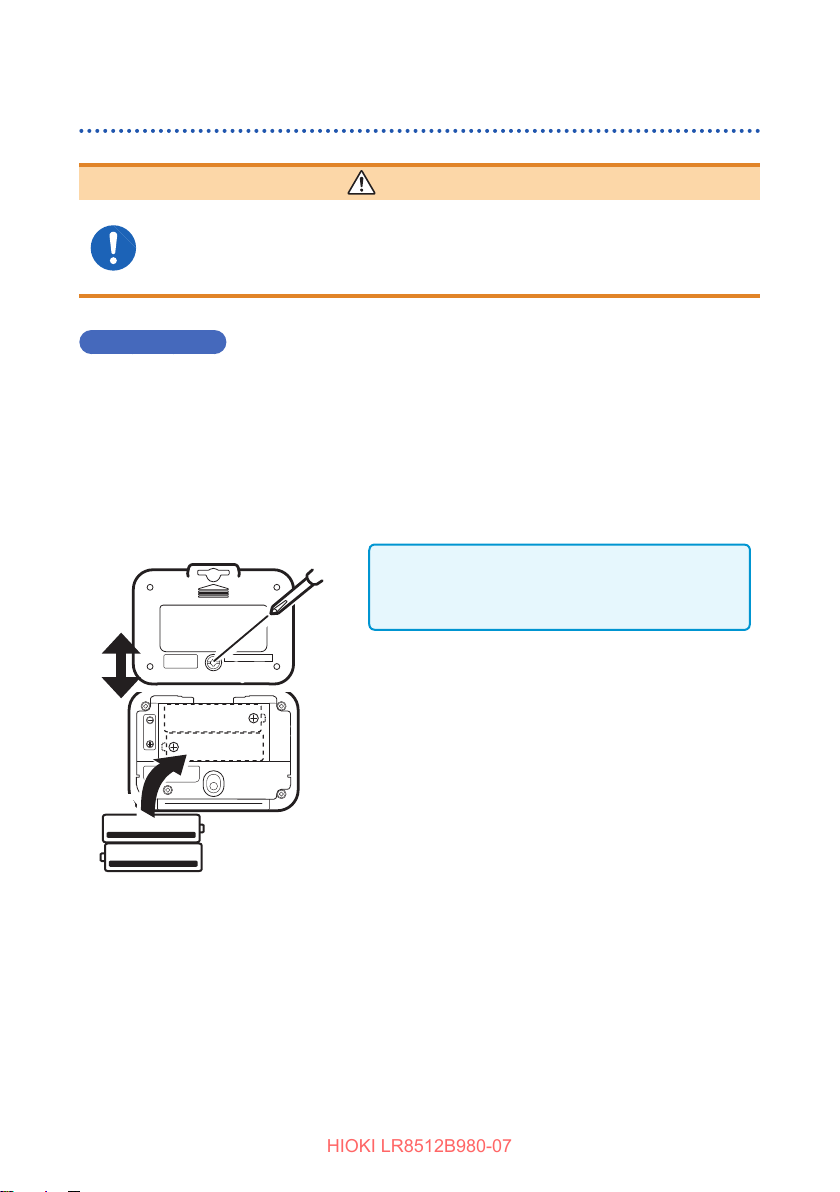
Remove the connection cables.
1
Using a Phillips screwdriver, remove the
2
screw (1 location) from the battery cover.
The screw cannot be removed from the
battery cover. Do not try to remove the screw
forcefully.
3
2, 7
6
Slide up and remove the cover.
3
Inserting/Replacing Batteries
5
4
Remove the old batteries (for battery
4
replacement).
Insert new batteries, being careful with the
5
battery polarity.
Slide down and reattach the battery cover.
6
Secure the cover with the screw.
7
31

Inserting/Replacing Batteries
HIOKI LR8512B980-07
When batteries are installed, the following screen is displayed.
1. All indicators on 2. Model
(Example: When the
LR8512 is used)
3. Version number
(Example: Version 1.00)
Battery indicator display
Displayed at the upper right corner of the display.
Fully charged.
As the battery charge diminishes, black charge bars disappear, one by one, from
the left of the battery indicator.
The battery voltage is low. Replace the batteries as soon as possible.
(Blinks) The battery is drained. Recording or communications cannot be made in
this condition.
O
IMPORTANT
Thedisplayedremainingbatterylevelmaybedierentfromtheactual
remaining battery level due to the battery characteristics, settings during
use, temperature or consumption level. When a battery is used in a low
temperature environment or a weak and deteriorated battery is used, the
powermayshutoregardlessofthebatteryindicatordisplay.
The battery indicator display turns o when the AC adapter or an external power
supply is connected.
32

Inserting/Replacing Batteries
HIOKI LR8512B980-07
Battery life indication
The battery life varies depending on the recording interval. In case of the free run
function, the battery life is the same as for 1 second regardless of the recording
interval setting. (when recording interval setting is more than 2 seconds)
LR8512 Wireless Pulse Logger
Recording interval
0.1 sec. 1 sec. 10 sec. 1 min.
Real-time measurement
Bluetooth ON
Manual data collection
Bluetooth ON
Manual data collection
Bluetooth OFF
LR8513 Wireless Clamp Logger
Real-time measurement
Bluetooth ON
Manual data collection
Bluetooth ON
Manual data collection
Bluetooth OFF
The values indicated in the table are for instant value recording. For average/maximum value
recording, the battery life is the same as for 0.5 sec. regardless of the recording interval.
Approx. 5 days Approx. 7 days Approx. 10 days Approx. 10 days
Approx. 14 days Approx. 14 days Approx. 14 days Approx. 14 days
Approx. 1.5
months
0.5 sec. 1 sec. 10 sec. 1 min.
Approx. 5 days Approx. 7 days Approx. 10 days Approx. 14 days
Approx. 10 days Approx. 10 days Approx. 20 days Approx. 20 days
Approx. 14 days Approx. 1 month
Approx. 2
months
Recording interval
Approx. 2
months
Approx. 2.5
months
Approx. 2
months
Approx. 3
months
LR8514 Wireless Humidity Logger
Real-time measurement
Bluetooth ON
Manual data collection
Bluetooth ON
Manual data collection
Bluetooth OFF
Recording interval
0.5 sec. 1 sec. 10 sec. 1 min.
Approx. 5 days Approx. 7 days Approx. 10 days Approx. 14 days
Approx. 20 days Approx. 20 days Approx. 20 days Approx. 20 days
Approx. 2.5
months
Approx. 3
months
Approx. 3.5
months
Approx. 3.5
months
33

Inserting/Replacing Batteries
HIOKI LR8512B980-07
LR8515 Wireless Voltage/Temp Logger
0.1 sec. 1 sec. 10 sec. 1 min.
Real-time measurement
Bluetooth ON
Manual data collection
Bluetooth ON
Manual data collection
Bluetooth OFF
Approx. 2 days Approx. 4 days Approx. 7 days Approx. 14 days
Approx. 3 days Approx. 7 days Approx. 14 days Approx. 20 days
Approx. 3 days Approx. 10 days
Recording interval
Approx. 1.5
months
Approx. 2.5
months
34

Connecting the AC Adapter
HIOKI LR8512B980-07
2.3 Connecting the AC Adapter
Connect the instrument, the optional Z2003 AC adapter, and power cord, and then
connect to an outlet.
When using the AC Adapter with a batteries, the AC Adapter has priority in powering
the instrument. When power from the AC Adapter is interrupted, the instrument or
module will switch to battery power.
Before connecting, make sure to read “AC adapter” (p.12) and “Handling of cords
and cables” (p.10).
Rated supply voltage: 100 V to 240 V AC
Rated supply frequency: 50 Hz/60 Hz
Connect the power
1
cord and AC adapter.
Connect the outlet
2
3
1
Power cord
AC adapter
2
plug to the instrument
AC adapter connection
terminal (left side).
Connect the output
3
plug to an outlet.
When the AC adapter is connected, the following screen is displayed.
1. All indicators on 2. Model
When the AC adapter is used, is lit at the upper right of the display.
ExternalPowerSupply
The instrument can work either on a DC power supply unit (5 V to 13.5 V DC) or the
USB bus power (5 V DC).
If you need a conversion cord to connect the instrument and an external power
supply unit, contact your authorized Hioki distributor or retailer.
(Example: When the
LR8512 is used)
3. Version number
(Example: Version 1.00)
35

Installing the Strap (optional)
HIOKI LR8512B980-07
2.4 Installing the Strap (optional)
When the optional Z5004/Z5020 Magnetic Strap is attached to the instrument, the
magnet can be attached to the wall surface (metal plate).
Attach the Z5004 or Z5020 through the strap hole.
1
In order of (1) → (2) → (3)
(1)
(2)
(3)
36
Magnet
Attach it to the wall surface (with a metal plate
2
axed).

Connecting Cables
HIOKI LR8512B980-07
2.5 Connecting Cables
Connecting the L1010 Connection Cable (LR8512)
Connect the connection cable to the LR8512 connection terminal.
Not
−
used
+
L1010 Connection Cable (length approx. 1.5 m)
Red wire: Voltage input (+)
+
−
Black wire: Voltage input (-)
• If a wrong input on the instrument side or connection destination is made or the
L1010 is not completely inserted, a correct value is not displayed.
• If a correct value is not displayed even when the L1010 is completely inserted,
the instrument or connection cable may have a problem. Send the instrument
for repair.
37

Connecting Cables
HIOKI LR8512B980-07
Connecting the clamp sensor (LR8513)
Connect the clamp sensor to the LR8513 connection terminal. Use the specied
clamp sensor. For more details, see the instruction manual supplied with the clamp
sensor.
Align the BNC connector groove of
1
the clamp sensor with the instrument
connector guide and insert it.
Turn it to the right to lock it.
2
When removing the connector, turn it to the
left and pull it out.
Clamp the object to be measured.
3
(p. 42)
• If it is not completely inserted, a correct
value is not displayed. If a correct value is
not displayed even when it is completely
inserted, the instrument or sensor may have
a problem. Send the instrument for repair.
• Do not connect any clamp sensor other than
the specied sensor.
1
BNC connector groove
Connector guide
CH2CH1
Clamp
sensor
2
Lock
Supported clamp sensor
Model Clamp sensor
9669
CT6500
9657-10
9675
CT9691-90
CT9692-90
CT9693-90
38
3
(The gure is for the
CT6500.)
*1
Clamp On Sensor9695-02
Clamp On Leak Sensor
Clamp On AC/DC Sensor

Connecting Cables
HIOKI LR8512B980-07
Model Clamp sensor
*2
CT7631
CT7642
CT7731
CT7736
CT7742
*2
*2
*2
*2
*2
AC/DC Current SensorCT7636
AC/DC Auto-Zero
Current Sensor
CT9667-01
CT9667-02
CT9667-03
*2
CT7044
*2
CT7045
*2
CT7046
*1
: The 9219 Connection Cord is required in order to connect a compatible clamp sensor.
*2:
The CM7290 or CM7291 Display Unit and L9095 Output Cord are required in order to connect
AC Flexible Current Sensor
a compatible clamp sensor.
39

Connecting Cables
HIOKI LR8512B980-07
Using the CT9691-90, CT9692-90 or CT9693-90
The CT9691-90, CT9692-90, and CT9693-90 are each composed of the CT9691,
CT9692, or CT9693 Clamp Sensor and CT6590 Sensor Unit.
CT6590 Sensor Unit overview and parts names
The CT6590 Sensor Unit is a unit to connect the CT9691, CT9692, and CT9693
Clamp ON AC/DC Sensor to the measuring instrument. The clamp sensor measures
current and the instrument converts and outputs the voltage signal. After connecting
the sensor to the measuring instrument, correct any deviation in the output using the
zero adjustment knob before starting measurement.
POWERLED
Green lamp lit:
Power ON
Red lamp lit:
Low battery
Lamp o: Power OFF
Zero adjustment knob
Turn the knob to the left or
right to adjust the zero point
of the connection sensor
.
Selector switch
H: High range
L: Low range
OFF: Power OFF
The range level varies
depending on the clamp
sensor.
RATING
BATTERY
2
LR6
2
Battery cover
Remove the screw and insert
batteries.
Sensor
connection
terminal
Connect the clamp
sensor.
Output rate and range of the CT9691-90, CT9692-90, and CT9693-90 Sensor
H Range (f.s.) 100 A 200 A 2000 A
Output rate 1 mV/A 1 mV/A 0.1 mV/A
L Range (f.s.) 10 A 20 A 200 A
Output rate 10 mV/A 10 mV/A 1 mV/A
Output (f.s.) 100 mV 200 mV 200 mV
40
AC adapter
connection
terminal
BNC connector
Connect the connector to
the LR8513.
CT9691 sensor CT9692 sensor CT9693 sensor

Measurement procedure
HIOKI LR8512B980-07
Connecting Cables
5
67
Zero adjustment
4
LR8513
0.00 A
2
CT6590 Sensor Unit
3
Supply power to the CT6590 Sensor Unit (battery or AC adapter).
1
There are two power supplies, batteries (accessory) and AC adapter (optional).
Use the AC adapter when operating the instrument continuously for a long period of time.
Connect the clamp sensor to the CT6590.
2
Connect the CT6590 to the LR8513.
3
Select the range with the selector switch.
4
Refer to “Output rate and range of the CT9691-90, CT9692-90, and CT9693-90 Sensor”
(p.40) and select the range appropriate for the measuring instrument.
The voltage corresponding to the input current is output.
For example, 100 mV is output for 10 A when the L range is selected on the CT9691.
The voltage corresponding to the input current is output.
For example, 100 mV is output for 10 A when the L range is selected on the CT9691.
Turn the zero adjustment knob and perform zero adjustment so that the
5
measured value indicates around 0 A in the instrument screen.
Before starting measurement, turn the zero adjustment knob on the CT6590 and correct
any deviation in the output.
• The zero adjustment knob has a design that is not easy to turn so it is not turned
accidentally after zero adjustment.
• If the measured value does not indicate around 0 A after zero adjustment, send
the CT6590 and clamp sensor for repair.
Wire the clamp sensor to the object to be measured.
6
After the measurement, remove the clamp sensor.
7
41

Connecting Cables
HIOKI LR8512B980-07
Using the CM7290 or CM7291
The CM7290/CM7291 Display Unit provides a Hioki PL14 output connector and is
used by connecting it to a current sensor.
Measurement procedure
5
6 -1
Select the
measurement mode
1
4
Perform zero-
adjustment
Press and hold
6 -2 6 -3
Select the
output mode
L9095 Output Cord
Connect the current sensor to the CM7290/CM7291.
1
Supply power to the CM7290/CM7291.
2
The CM7290/CM7291 can operate on AC adapter or battery power.
Connect output from the CM7290/CM7291 to the LR8513 with the L9095
3
Output Cord.
Perform zero-adjustment for the current sensor.
4
The CT7044, CT7045, and CT7046 do not require zero-adjustment
Connect the current sensor to the conductor being measured.
5
Select the
output rate
LR8513
0.00 A
3
42

Connecting Cables
HIOKI LR8512B980-07
Congurethecurrentsensor.
6
-1. Select the measurement mode. AC. DC. AC/DC
-2. Select the output mode.
-3. Select the output rate.
Refer to “The table of output rates and corresponding measurement ranges”.
StartmeasurementafterconguringtheLR8513.
7
To congure the LR8513 settings, see"LR8513 Wireless Clamp Logger" (p. 75)
Once measurement is complete, disconnect the current sensor from the
8
conductorbeingmeasuredandturnotheLR8513.
The values displayed by the CM7290/CM7291 and the LR8513 may dier due to dierences
in the devices’ accuracy.
When measuring a negative DC current in AC/DC measurement mode, the CM7290/CM7291
and LR8513 may indicate dierent polarity readings.
The table of output rates and corresponding measurement ranges
Model CM7290/CM7291
output rates
CT7631/CT7731 10mV/A 10A
1mV/A 100A
CT7636/CT7736 10mV/A 20A
1mV/A 200A
CT7642/CT7742 1mV/A 200A
0.1mV/A 2000A
CT7044/CT7045/CT7046 10mV/A 50A
1mV/A 500A
0.1mV/A 5000A
Disable the CM7290/CM7291’s 10× output function.
LR8513
measurement ranges
43

Connecting Cables
NO
NO
NO
HIOKI LR8512B980-07
Connecting to a conductor
Clamp only one conductor with the clamp sensor for measurement.
NOOK
9669, 9695-02, CT6500 Clamp On Sensor
CT9691-90, CT9692-90, CT9693-90 Clamp On AC/DC Sensor
(The gure is for the CT6500.)
OK
9675, 9657-10 Clamp On Leak Sensor
(The gure is for the 9675.)
• For details, refer to the instruction manual for the clamp sensor to be used.
• A wrong measurement procedure could result in injury or death, as well as damage
to the instrument.
OK
NO
NO
44

Connecting Cables
HIOKI LR8512B980-07
For leak current measurement
The 9675, 9657-10 Clamp On Leak Sensor can be used.
Clamp the conductor at the center of the clamp core.
When the measurement current level is unknown, set the range level to the 5 A range before
starting measurement.
Measurement with a ground cable
Single-phase/3-wire circuit
Transformer
Leak
Class B ground
cable
current lg
Batch measurement
Single-phase/3-wire circuit Three-phase/3-wire circuit
Transformer
Leak
current lg
• For a single-phase/2-wire circuit, clamp 2-wires.
• For a three-phase/4-wire circuit, clamp 4-wires. When the wires cannot be clamped, you
can still measure using the equipment ground cable.
• If a wire close to the instrument carries a large current, correct measurement may not be
performed. Ensure enough distance for measurement.
• Do not input current exceeding the continuous maximum input in the measurement range.
• When the clamp is opened or the current range is changed, tens of counts may be
displayed, however, this is not a problem. It takes time but the display gradually drops to
0. If measurement is performed before the display returns to 0, the measurement is not
aected.
• The accuracy of AC voltage overlapped with a DC component cannot be guaranteed.
Clamp 3-wires at a time.
Class B
ground cable
Loading
equipment
Clamp all the wires at the center.
Loading
equipment
Clamp only one conductor.
Three-phase/3-wire circuit
Leak current
Class B
ground cable
Leak
current lg
lg
Clamp 3-wires at a time.
Class B ground
cable
Loading
equipment
Class D ground cable
Loading
equipment
Class D ground cable
45

Connecting Cables
HIOKI LR8512B980-07
Inspection for areas with insulation deterioration
1. Measure the leak current in the entire circuit and determine whether there is
any short-circuit based on a change in the current. Normally leak current is
measured with the Class B ground cable of the transformer.
Single-phase/3-wire circuit
Load
Class B
Leak
current lg
2. If any short-circuit is found, inspect from the power supply to the load using batch
measurement (circuit clamped all at a time).
ground
cable
a
’a
equipment
b
Leak
current lg
• If wire insulation deterioration is found at A in the gure, batch measurement a can
detect a leak current but not ’a.
• If loading equipment insulation deterioration is found at B in the gure, batch
measurement b can detect a leak current but not ’b.
Class B
ground
cable
Insulation
deteriorated
area A
Load
equipment
Insulation
deteriorated area B
’b
46

Connecting Cables
HIOKI LR8512B980-07
For load current measurement
Tuck in the conductor at the center of the clamp core.
• Any special waveforms like the secondary side of an inverter cannot be measured.
• When the measurement current level is unknown, set the range level to the following before
starting measurement.
Model Clamp sensor Range
9695-02
CT6500
9669
9675
9657-10
CT9691-90
CT9692-90
CT9693-90
CT7631
CT7636
CT7642
CT7731
CT7736
CT7742
CT9667-01
CT9667-02
CT9667-03
CT7044
CT7045
CT7046
Clamp On Sensor
Clamp On Leak Sensor
Clamp On AC/DC Sensor
AC/DC Current Sensor
AC/DC Auto-Zero
Current Sensor
AC Flexible Current
Sensor
50 A range
500 A range
1000 A range
5 A range
5 A range
100 A range
200 A range
2000 A range
100 A range
200 A range
2000 A range
100 A range
200 A range
2000 A range
5000 A range
5000 A range
5000 A range
5000 A range
5000 A range
5000 A range
47

Connecting Cables
HIOKI LR8512B980-07
Connecting the temperature and humidity sensor (LR8514)
Attach one or two pieces of Humidity Sensor to the connection terminals of the
LR8514 Wireless Humidity Logger.
Supported sensors
Z2010 Humidity Sensor Length including the sensor: Approx. 50 mm
Z2011 Humidity Sensor Cable length: Approx. 1.5 m
Right side of
instrument
Z2010 or Z2011 Humidity Sensor
CH1
CH2
• When the temperature and humidity sensor is not completely inserted, [BURN
OUT] is displayed for the measurement value and [BURN] is displayed on the
screen.
• If a correct value is not displayed even when the sensor is completely inserted,
the instrument or the sensor may have a problem. Send the instrument for
repair.
Completely insert the
temperature and humidity
sensor into the CH1 or CH2
input terminal.
Connecting the input cable/thermocouple (LR8515)
Attach input cables or thermocouples to the terminal block of LR8515 Voltage/Temp
Logger.
Loosen the terminal block screws. Insert the
1
wiresofthecableasshowninthegureand
tighten the screws.
Tighten the terminal block screws at 0.8
N•m or lower (0.4 N•m is recommended).
Connect the cable to the measurement
CH1
–
+
+
Input cable/
Thermocouple
CH2
–
2
object.
IMPORTANT
Kthermocouplesexperienceaphysical
phenomenon known as short range
ordering, which can prevent accurate
measurement within the range of 250°C
to 600°C. Please choose a sensor after
checking with the manufacturer of the
thermocouple you intend to use.
48

3
HIOKI LR8512B980-07
There are two ways.
Real-time measurement using the LR8410
Real-time measurement using a Windows® PC
Using the LR8410 as a Unit
(Line-of-sight 30 m)
LR8410
LR8410
Windows® PC
(Logger Utility)
(Line-of-sight 30 m)
LAN/USB
communications
3.1 Real-time Measurement Using the LR8410
Turn ON the power of the instrument and the LR8410.
1
Register the instrument as a unit using the LR8410 Quick Set function (Unit
2
Guide).
SetthemeasurementconditionsusingtheQuickSetfunction(Cong
3
Guide) and send the conditions to the instrument.
Start measurement.
4
For details, refer to the LR8410 measurement guide.
49

Performing Real-time Measurement Using a Windows® PC
HIOKI LR8512B980-07
3.2 Performing Real-time Measurement Using a
®
Windows
RegistertheinstrumentasaunitintheLR8410.(p. 49)
1
Install Logger Utility on the Windows® PC.
2
Start up Logger Utility.
3
The main screen is displayed when Logger Utility starts up.
The main screen is the basic screen for Logger Utility.
PC
Logger Utility
Set the measurement conditions for the instrument.
4
Send the measurement conditions to the instrument.
5
Start or stop measurement.
6
For details, refer to the Logger Utility instruction manual on the provided CD.
50

Collecting Measurement Data
HIOKI LR8512B980-07
4
Using a Windows
Windows® PC
(Line-of-sight 30 m)
4.1 SoftwareSpecications
System requirements
CPU 1 GHz or faster 32-bit or 64-bit processor
Memory 1 GB or more of RAM (32-bit) or 2 GB or more of RAM (64-bit)
Display 1,024 × 768 dots or more, 65,536 colors or more
(Recommended: Use a small font. When a large font is used, the
display may be disturbed.)
Hard disk 3.0 GB or more of available space
OS Windows 10 (32-bit/64-bit), Windows 8 (32-bit/64-bit),
Windows 7 (32-bit/64-bit)
Communication
method
Bluetooth 2.1+EDR or higher
Prole: SPP
(Recommended: Use the Windows
®
PC
• Wireless Logger Collector
• Logger Utility
®
standard protocol stack.)
51

Software Specications
HIOKI LR8512B980-07
Functionspecications
Number of allowable
registrations
Settings Measurement settings can be edited/copyed/initialized and sent/
Measurement control Measurement can be started and stopped.
Monitoring function The status can be monitored.
Measurement data
collection function
Analysis/browsing Measurement data can be displayed in the waveform format and
Measurement data
output
Other Clock setting, self-diagnosis, version number check, and rmware
100 units
received.
The status can be monitored repeatedly and periodically (10
minutes to 1 day).
Numerical values can be monitored.
Update interval: 1 second
Measurement data can be collected.
Measurement data can be collected repeatedly and periodically (10
minutes to 1 day).
analyzed using the Logger Utility.
Measurement data can be output to a le in the following formats.
Logger Utility format, LR5000 format, Smart Site compatibility
format, CSV format, and text format
Measurement data can be combined.
Measurement data obtained with several instruments can be
combined to output as one le (in Logger Utility general-purpose
data format).
version update
52

Measurement Workow
HIOKI LR8512B980-07
4.2 MeasurementWorkow
Install the instrument referring to “Preparation for Measurements”
1
(p. 29).
Install the software on the Windows®PC.(p. 55)
2
• Wireless Logger Collector
• Logger Utility
Register the instrument in Wireless Logger Collector (up to 100 units).
3
(p. 61)
When no wireless logger is found
• When the
function.
• When the
instrument closer to the PC or remove any obstacle and then search for the logger again.
SetthemeasurementconditionsinWirelessLoggerCollector.(p. 67)
4
(1)
symbol in the screen is o, press the power key to turn ON the Bluetooth
symbol in the screen is o, a wireless connection is not established. Place the
(4)
(3)
(2)
53

Measurement Workow
HIOKI LR8512B980-07
Sendthemeasurementconditionstotheinstrument.(p. 96)
5
Startmeasurement.(p. 98)
6
Please be advised that if you start recording, the previously acquired data
retained in the internal memory will be deleted.
You can also start
measurement by
holding down this
button.
CollectmeasurementdatausingWirelessLoggerCollector.(p. 101)
7
Measurement data can be collected during measurement and after
measurement stop.
54

Installing the Software
HIOKI LR8512B980-07
Analyze the data on the Windows® PC.
8
1. Display measurement data in the
Logger Utility:
2. Output the collected data in the
CSVleformat:
“Exportingmeasurementdata”
(p. 103)
The data is displayed in a graph and analyzed.
(p. 102)
The data is displayed in a graph using a
spreadsheet program, such as Microsoft
®
Excel
4.3 Installing the Software
Installation
Install the software according to the following procedure.
Displayed messages and operations may be dierent depending on the operating
system or settings.
Close all the software that is running.
1
IMPORTANT
If any anti-virus software is running, make sure to close it before starting the
installation. If anti-virus software is running, the software may not be installed
properly.
®
Set the provided CD in the CD-ROM drive.
2
The language selection screen is automatically displayed.
If the screen is not displayed, start the explorer to nd the [index.htm] le and
open it with a web browser.
Click [English]
3
The menu will appear.
Click [Logger Utility Wireless Logger Collector]
4
Click [Install]
5
The installer starts automatically. If the installer does not start, execute [Setup.
exe] on the CD.
Install the software according to the instructions displayed by the
6
installer.
Two applications, Logger Utility and Wireless Logger Collector, are installed.
55

Installing the Software
HIOKI LR8512B980-07
Startup procedure
For Windows 7
From the Windows Start menu, click [All Programs] - [HIOKI] - [Logger Utility] -
[Wireless Logger Collector].
For Windows 8
From the Start window, display the [Apps] view and click [HIOKI] - [Wireless Logger
Collector].
For Windows 10
From the Windows Start menu, click [All Apps] - [HIOKI] - [Wireless Logger
Collector].
Termination procedure
In the main screen, click the application button and then click [Exit] in the displayed
menu.
Or click the Close key [
56
] at the upper right of the main screen.

Installing the Software
HIOKI LR8512B980-07
Uninstallation
Remove the software according to the following procedure.
Open Control Panel.
1
For Windows 7:
From the Windows Start menu, click [Control Panel].
For Windows 8:
From the Start window, display the [Apps] view and click [Windows System] -
[Control Panel].
For Windows 10:
Right-click the Windows Start button, and then click [Control Panel].
Click [Programs and Features].
2
The [Uninstall or change a program]
screen is displayed.
Double-click [HIOKI Logger Utility] in the list of installed programs.
3
As the measurement data and setting les remain as they are, delete them
manually if they are not needed.
57

Display Conguration
HIOKI LR8512B980-07
4.4 DisplayConguration
The main screen is displayed when the application starts up.
1 2
4 5 89
Name Description
Application button Displays the option menu, etc.
1
Quick access tool bar Right-click and customize the Ribbon bar.
2
Ribbon Allows you to operate or edit the items displayed in the list.
3
Navigation bar • Registers and sets wireless loggers.
4
Wireless logger list (tree
5
display)
Title display Displays the information on the wireless logger that is
6
Wirelesslogger/channel/le
7
list (list display)
Output (log) • Displays operation results and errors.
8
Status bar • Number of items: Displays the total number of items.
9
3 6 7
• Performs measurement and monitoring.
• Collects and browses measurement data.
• Performs wireless logger maintenance.
• Switches the group display and list display.
• Creates and deletes groups.
currently selected.
Displays the settings and wireless logger status.
• The log can be copied and cleared.
• Number of selections: Displays the number of selected items.
• Status display: Sending/receiving settings, monitoring
status, controlling measurement, collecting data,
performing maintenance
58

Basic Operation Procedure
HIOKI LR8512B980-07
4.5 Basic Operation Procedure
Operationow
1 2 3
4
Select one of the following categories from the Navigation bar.
1
[Register/Settings], [Measurement/Monitoring], [Collection/Browse],
[Maintenance]
Select a group and wireless logger from the wireless logger list (tree
2
display).
Selecttheitemtobedisplayedfromthewirelesslogger/channel/lelist
3
(list display).
Press the operation button of the Navigation bar.
4
Or right-click the item in the list and select the operation from the displayed
menu.
59

Basic Operation Procedure
HIOKI LR8512B980-07
Selecting multiple wireless loggers
Search/Select
From all the registered wireless loggers, communicative wireless loggers are
searched for and selected automatically.
• This button may not be used depending on the PC specications.
• This button may not be selected depending on the communications with the
wireless logger.
Select all
Click [Select All] on the Ribbon bar.
Unselect
Click [Unselect] on the Ribbon bar.
Select individual
Click a checkbox in the list.
Select multiple
Click the item in the list while pressing the Ctrl key or Shift key.
• The number of selected items is displayed on the Status bar.
• The checked items have priority over the selected items (highlighted items) in the
list.
60

Registering/Deleting a Wireless Logger
HIOKI LR8512B980-07
4.6 Registering/Deleting a Wireless Logger
Registering a wireless logger
Register a wireless logger in Wireless Logger Collector. Up to 100 wireless loggers
can be registered.
IMPORTANT
Some functions of Wireless Logger Collector may not be used depending on
thePCspecications.Communicationsmaynotbeestablisheddepending
on the combination of the Bluetooth module and Bluetooth stack (device
driver).
Preparation
Place the wireless logger near the Windows® PC (where there is no
1
communications interference).
Turn on the wireless logger power ( ).
2
(The instrument is powered up automatically when the AC adapter or battery is
installed.)
Check that the Bluetooth power is ON ( Lit).
61

Registering/Deleting a Wireless Logger
HIOKI LR8512B980-07
Registration
1
3
2
4
Select [Register/Settings] - [Register/remove device] of the Navigation bar.
1
The [Register/remove device] dialog box is displayed.
Click
2
3
4
5
[Search].
The nearby wireless loggers or wireless loggers that have been connected
are displayed in the list on the left. (COM ports are displayed if a third party
Bluetooth stack is used.)
Select the wireless logger(s) to be registered from the list on the left
(multiple units can be selected).
Press [ ] to register the selected wireless logger(s).
The selected wireless logger(s) moves to the list on the right.
Press [OK].
5
62

Registering/Deleting a Wireless Logger
HIOKI LR8512B980-07
• When a Windows® standard Bluetooth stack is used, the model name and serial
number are displayed in “Found devies”.
To check whether Windows
Panel] - [Device Manager], open [Bluetooth Radios], and then check if
[MicrosoftBluetoothEnumerator] is displayed.
• When a Windows® non-standard Bluetooth stack is used, the model name
and serial number are not displayed. Make paring and virtual COM settings in
the software provided with the Bluetooth stack and then register the wireless
loggers. When an unauthorized virtual COM is registered, the operation of
Wireless Logger Collector may become unstable.
Ways of performing a pairing and creating a virtual serial port vary depending on
your computer and Bluetooth stack. Please direct the inquiries to manufactures
of them for details.
®
standard Bluetooth stack is enabled, select [Control
ExampleofhowtoallocateVirtualCOMport
Open [Control Panel] - [Device and Printers] or [Bluetooth].
1
Click “Add a device” and select a wireless logger which would like to
2
do a pairing.
When a pairing is completed, the wireless logger is registered with a list.
Open [Property] of registered wireless logger and check the assigned
3
virtual COM port number.
63

Registering/Deleting a Wireless Logger
HIOKI LR8512B980-07
Deleting a wireless logger
Delete the wireless logger that is registered in Wireless Logger Collector (registration
cancel).
1
2
Select [Register/Settings] - [Register/remove device] of the Navigation bar.
1
The [Register/remove device] dialog box is displayed.
Select the wireless logger(s) to be deleted from the list on the right
2
(multiple units can be selected).
Press [ ] to delete the selected wireless logger(s).
3
The selected wireless logger(s) moves to the list on the left.
Press [OK].
4
The collected measurement data is not deleted even when wireless loggers are
deleted (registration cancel).
Delete the measurement data manually if it is not needed.
64
3
4

Registering/Deleting a Wireless Logger
HIOKI LR8512B980-07
Grouping wireless loggers
Wireless loggers can be grouped and managed. Grouping is useful for managing
multiple wireless loggers. Groups can be added to the layered structure.
Procedure to create a group
2
1
From [List] (the wireless logger list [tree display]), select [Computer] or
1
the group for which a new group is to be created.
Press [ ].
2
A new group is now created.
EnteragroupnameandpresstheEnter key.
3
65

Registering/Deleting a Wireless Logger
HIOKI LR8512B980-07
Procedure to move a group
From [List] (the wireless logger list [tree display]), drag the wireless logger to be
moved using the left key of the mouse and drop it on the target group.
Drag and drop
Procedure to delete a group
From [List] (the wireless logger list [tree display]), select the group to be
1
deleted.
Press [ ].
2
If wireless loggers are registered in the deleted group, they move to under
[Computer].
66
2
1

Setting Measurement Conditions
HIOKI LR8512B980-07
4.7 Setting Measurement Conditions
Set the measurement conditions for wireless loggers.
3
2
1
Select [Register/Settings] from the Navigation bar.
1
Select the target wireless logger.
2
Click [Open] on the Ribbon bar.
3
The settings dialog box is displayed.
67

Setting Measurement Conditions
HIOKI LR8512B980-07
Setting measurement
Recording Interval
Allows you to set the interval to import data.
Settings:
100ms, 200ms, 500ms, 1s, 2s, 5s, 10s, 20s, 30s, 1min, 2min, 5min, 10min, 20min, 30min,
1hour
Recording interval
• Select the recording interval according to the object to be measured.
• The peak of the waveform may not be measured depending on the recording
interval setting.
• For the LR8515 Wireless Voltage/Temp Logger, the recording interval cannot be
set to 100ms when disconnection detection is set to ON.
Example: When the recording interval is set to 1s
Peak
1s
Continuous Recording
Allows you to set a processing method when the memory is full.
Settings:
O(One-time) Stops recording when the memory is full.
On(Endless) Overwrites old data when the memory is full.
Digital Filter (LR8515 only)
Setting the digital lter to ON can remove noise in input signals. Set the lter to 50 Hz
or 60 Hz according to the power frequency in the region where it is used.
Settings:
50 Hz 50 Hz power noise can be removed.
60 Hz 60 Hz power noise can be removed.
68

Setting Measurement Conditions
HIOKI LR8512B980-07
Title Comment
Allows you to set the title comment. (Up to 40 single-byte characters)
The characters entered are converted to the following symbols.
^2
^3
~u μ
~c °
~e
2
(Superscript)
3
(Superscript)
ε
Scheduled Record Start
Measurement can be started at the specied time.
If the current time has passed the preset time, measurement is not started.
Settings:
OFF (The preset start function is disabled.)
Starts recording at the preset time.
The instrument enters the recording start standby state at the same time as
the Scheduled Record Start ON setting is sent. Measurement start by signal
communications cannot be accepted in this state.
Scheduled Record Stop
Measurement can be stopped at the specied time.
If the current time has passed the preset time, measurement is not stopped.
Settings:
OFF (The preset stop function is disabled.)
Stops recording at the preset time.
69
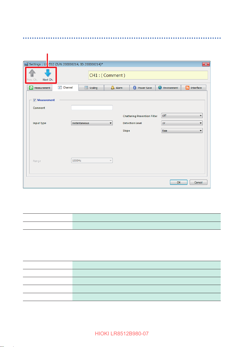
Setting Measurement Conditions
HIOKI LR8512B980-07
Setting the channel
The channel to be set is switched.
Measurement
Allows you to set measurement to ON/OFF.
Settings:
Comment
Allows you to set the channel comment. (Up to 40 single-byte characters)
The characters entered are converted to the following symbols.
^2
^3
~u μ
~c °
~e
70
Does not perform measurement.
Performs measurement.
2
(Superscript)
3
(Superscript)
ε

Setting Measurement Conditions
HIOKI LR8512B980-07
LR8512 Wireless Pulse Logger
Making settings for integrated measurement
The number of integrated pulses output from the integrated power meter or ow
meter is measured.
1
: ON
2
1
5
4
3
SelectthechanneltobesetandchecktheMeasurementcheckbox[]
1
(ON).
Select the input type.
2
Settings:
Instantaneous
Add
Measures the number of pulses input to the instrument within the
recording interval.
The number of pulses is reset for each recording interval.
Measures the number of integrated pulses after measurement starts.
HIGH
Detection
level
LOW
Select the measurement reference (slope).
3
Settings:
Rise
Fall Integrates the number of times the pulse changes from
Select the HIGH/LOW reference value (detection level).
4
Settings:
1 V
4 V
AdditionInstantaneous
Integrates the number of times the pulse changes from LOW to HIGH.
HIGH
to
LOW
Determines 1.0 V or higher to be HIGH, 0 V to 0.5 V to be LOW
Determines 4.0 V or higher to be HIGH, 0 V to 1.5 V to be LOW.
.
.
71

Setting Measurement Conditions
HIOKI LR8512B980-07
Selectthechatteringpreventionltersetting.
5
Settings:
OFF
ON
• With the scaling function, the number of integrated pulses can be converted to a
physical quantity (Wh, VA, etc.) for the object to be measured. (p. 81)
• If there is a possibility that the number of pulses may exceed 1,000,000,000, it is
recommended to perform measurement with the input type “Instantaneous” and
add the measurement values using Microsoft
• If the waveform level signicantly exceeds the measurable scope of each range,
measured values will be treated as [+OVER] or [−OVER] with [O.F.] or [U.F.]
displayed, respectively.
The saved data will include values listed in “Handling Data” in the Appendix
(p. Appx.6).
Making settings for rotation speed measurement
The number of pulses output according to the rotation speed of the rotary encoder or
speed recorder is measured. The number of input pulses for one second is counted
and the rotation speed is calculated.
Turns OFF the chattering prevention lter.
Turns ON the chattering prevention lter.
For mechanical contact (relay) output signals, a count error due to
chattering can be prevented.
®
Excel® later.
1
: ON
SelectthechanneltobesetandchecktheMeasurementcheckbox[]
1
(ON).
Select [Rotation].
2
Set the number of pulses per rotation output from the sensor.
3
Settings:
1 to
1,000
The range is automatically set according to the number of pulses.
72
6
2
5
4
3

Setting Measurement Conditions
HIOKI LR8512B980-07
Select the measurement reference (slope).
4
Settings:
Rise Measures the rotation speed based on LOW to HIGH.
Fall Measures the rotation speed based on HIGH to LOW.
HIGH
Detection level
LOW
Select the HIGH/LOW reference value (detection level).
5
Settings:
1 V Determines 1.0 V or higher to be HIGH, 0 V to 0.5 V to be LOW.
4 V Determines 4.0 V or higher to be HIGH, 0 V to 1.5 V to be LOW.
Selectthechatteringpreventionltersetting.
6
Settings:
OFF
ON
Turns OFF the chattering prevention lter.
Turns ON the chattering prevention lter.
For mechanical contact (relay) output signals, a count error due to
chattering can be prevented.
If the waveform level signicantly exceeds the measurable scope of each range,
measured values will be treated as [+OVER] or [−OVER] with [O.F.] or [U.F.]
displayed, respectively.
The saved data will include values listed in “Handling Data” in the Appendix
(p. Appx.6).
73

Setting Measurement Conditions
HIOKI LR8512B980-07
Making settings for logic measurement
Logic signals are measured.
1
: ON
4
2 3
SelectthechanneltobesetandchecktheMeasurementcheckbox[] (ON).
1
Select [Logic].
2
Select the HIGH/LOW reference value (detection level).
3
Settings:
1 V Determines 1.0 V or higher to be HIGH, 0 V to 0.5 V to be LOW.
4 V Determines 4.0 V or higher to be HIGH, 0 V to 1.5 V to be LOW.
Selectthechatteringpreventionltersetting.
4
Settings:
OFF
ON
74
Turns OFF the chattering prevention lter.
Turns ON the chattering prevention lter.
For mechanical contact (relay) output signals, a count error due to chattering
can be prevented.

Setting Measurement Conditions
HIOKI LR8512B980-07
LR8513 Wireless Clamp Logger
Making settings for current measurement
The current is measured.
1
: ON
4
5
2
3
6
SelectthechanneltobesetandchecktheMeasurementcheckbox[] (ON).
1
Select the clamp sensor to be used.
2
Settings:
9675, 9657-10, 9695-02, CT6500, 9669, CT9691-90,
CT9692-90, CT9693-90, CT7631*
CT7742*2, CT9667*
1*2
, CT7044*2, CT7045*2, CT7046*
2
, CT7636*2, CT7642*2, CT7731*2, CT7736*2,
2
*1: Select CT9667 for the CT9667-01, CT9667-02, and CT9667-03.
*2: The Model LR8513 Wireless Clamp Logger rmware version 1.40 or later is required
to be installed to use the following clamp sensors: CT7044, CT7045, CT7046, CT7631,
CT7636, CT7642, CT7731, CT7736, CT7742, or CT9667.
Select the measurement range according to the object to be measured.
3
Settings:
9675
9657-10
9695-02
CT6500
9669
CT9691-90
CT9692-90
CT9693-90
500 mA, 5 A
500 mA, 5 A
5 A, 50 A
50 A, 500 A
1000 A
10 A, 100 A
20 A, 200 A
200 A, 2000 A
75

Setting Measurement Conditions
HIOKI LR8512B980-07
CT7631 10 A, 100 A
CT7636 20 A, 200 A
CT7642 200 A, 2000 A
CT7731 10 A, 100 A
CT7736 20 A, 200 A
CT7742 200 A, 2000 A
CT9667 500 A, 5000 A
CT7044 50 A, 500 A, 5000 A
CT7045 50 A, 500 A, 5000 A
CT7046 50 A, 500 A, 5000 A
Select the zero suppression setting.
4
Settings:
ON
OFF
Select the recording mode.
5
Settings:
Instantaneous
Average
Maximum*
*: The Model LR8513 Wireless Clamp Logger rmware version 1.30 or later is required to
be installed to use the instrument with the recording mode setting set to Maximum.
Selecttheltersetting.
6
Settings:
OFF
ON
Suppresses the value to zero when the count is less than 10 in each range.
Displays the value even when the count is less than 10 (for zero
adjustment for DC measurement).
Records the instant value for each recording interval.
Measures every 0.5 seconds and records the average value for each
recording interval. (When the recording interval is less than 1 second,
the instant value is recorded.)
Measures every 0.5 seconds and records the maximum value for each
recording interval. (When the recording interval is less than 1 second,
the instant value is recorded.)
Does not use the lter.
Current measurement including high-frequency components can be
performed.
For 50 Hz/60 Hz current measurement, unnecessary high-frequency
components can be cut.
• With the scaling function, the measured current value can be displayed in a
power value. (p. 81)
• If the waveform level signicantly exceeds the measurable scope of each range,
measured values will be treated as [+OVER] or [−OVER] with [O.F.] or [U.F.]
displayed, respectively.
The saved data will include values listed in “Handling Data” in the Appendix
(p. Appx.6).
76

Setting Measurement Conditions
HIOKI LR8512B980-07
LR8514 Wireless Humidity Logger
Making settings for temperature and humidity measurement
The temperature and humidity are measured using the Z2010/Z2011 Temperature
and Humidity Sensor.
1
: ON
SelectthechanneltobesetandchecktheMeasurementcheckbox[] (ON).
1
Disconnection Detection
[BURN OUT] is displayed for the measurement value and [BURN] is displayed on the
screen under the following conditions.
The saved data will include values listed in “Handling Data” in the Appendix (p. Appx.6).
• When the temperature and humidity sensor is not connected
• When the cable of the temperature and humidity sensor is cut
• When the temperature and humidity sensor fails
• When a communications error occurs with the temperature and humidity sensor due to
noise
If the waveform level signicantly exceeds the measurable scope of each range,
measured values will be treated as [+OVER] or [−OVER] with [O.F.] or [U.F.]
displayed, respectively.
The saved data will include values listed in “Handling Data” in the Appendix
(p. Appx.6).
77

Setting Measurement Conditions
HIOKI LR8512B980-07
LR8515 Wireless Voltage/Temp Logger
Making settings for voltage measurement
The channel is set for performing voltage measurement.
1
: ON
2
3
SelectthechanneltobesetandchecktheMeasurementcheckbox[]
1
(ON).
Select [Voltage].
2
Select the measurement range according to the object to be measured.
3
Settings:
50 mV, 500 mV, 5 V, 50 V
When measuring the output from a measurement instrument
When inputting a 4 mA to 20 mA current, connect a 250 Ω resistor between the + and
- sides of the analog input terminal as shunt resistance and measure the output in the
[5V] range.
With the scaling function, the display value can be converted to any value. (p. 81)
If the waveform level signicantly exceeds the measurable scope of each range,
measured values will be treated as [+OVER] or [−OVER] with [O.F.] or [U.F.]
displayed, respectively.
The saved data will include values listed in “Handling Data” in the Appendix
(p. Appx.6).
78

Setting Measurement Conditions
HIOKI LR8512B980-07
Making settings for temperature (thermocouple) measurement
The temperature is measured using a thermocouple.
1
: ON
5
2
3
4
SelectthechanneltobesetandchecktheMeasurementcheckbox[]
1
(ON).
Select [Thermocouple].
2
Select the thermocouple type.
3
Settings:
K, T
Select the disconnection detection setting.
4
Settings:
OFF
ON
• When disconnection detection is set to ON, a ne current is input at the specied
recording interval during thermocouple measurement and a thermocouple
disconnection is detected.
• As a disconnection is detected at a dierent timing to measurement, disconnection
detection does not aect measurement values.
• Disconnection detection cannot be set at a recording interval of 100 ms.
Does not perform disconnection detection. Normally when the thermocouple
is disconnected, a measurement value may become unstable.
Performs disconnection detection. [BURN OUT] is displayed for the
measurement value and [BURN] is displayed on the screen when the
thermocouple is disconnected. The saved data will include values listed in
“Handling Data” in the Appendix (p. Appx.6).
79

Setting Measurement Conditions
HIOKI LR8512B980-07
• When using an extended thermocouple for disconnection detection, use a
thermocouple with a large wire diameter. When the +f.s. temperature is measured
and the resistance value of the thermocouple exceeds the following value,
sometimes a disconnection is detected.
Thermocouple K: 960
Thermocouple T: 5,820
Select the reference junction compensation setting.
5
Internal
External
Ω
Ω
Implements reference junction compensation inside the instrument.
This setting is made when a thermocouple (or compensating lead wire)
is connected directly to the instrument. The measurement accuracy is
the value obtained when the temperature measurement accuracy and
reference junction compensation accuracy are added.
Does not implement reference junction compensation for this instrument.
This setting is made when a reference junction compensator (0°C ice
water, etc.) is externally connected. The measurement accuracy is the
temperature measurement accuracy only.
If the waveform level signicantly exceeds the measurable scope of each range,
measured values will be treated as [+OVER] or [−OVER] with [O.F.] or [U.F.]
displayed, respectively.
The saved data will include values listed in “Handling Data” in the Appendix
(p. Appx.6).
80

Setting Measurement Conditions
HIOKI LR8512B980-07
Setting scaling (as needed)
The input value can be converted to a physical quantity of the object to be measured
from voltage to current, etc.
Normal display (OFF) With scaling
Setting scaling for voltage, current, temperature, humidity, and rotation speed
measurement
1
3
2
4
Select the display format of the scaling value.
1
Settings:
Decimal Displays the converted value as a decimal number.
Exponential
Select the scaling method.
2
Settings:
Set by Ratio
Set by 2 Points
OFF No scaling
Displays the converted value as an index number. Wireless logger
display is in a decimal number only.
Converts the value to a physical quantity (conversion ratio) per 1 V
of the input signal, oset, and unit.
Converts the value voltage at 2 points of the input signal and the
converted value and unit of the 2 points.
81

Setting Measurement Conditions
HIOKI LR8512B980-07
Set the unit to be converted (up to 7 single-byte characters).
3
The characters entered are converted to the following symbols.
^2
^3
~u μ
~c °
~e
WhenRatioisselected,settheconversionratioandoset.
4
2
(Superscript)
3
(Superscript)
ε
When 2 Points is selected, set the value for 2 points before and after
conversion.
Setting by the ratio
Unit (eu)
Inclination
(Conversion
ratio: eu/v)
Oset
Value of the unit to be converted
Setting by 2 points
(Example)
A
H
A
L
V
V
L
Actual measurement value (input value)
[V]
H
Unit [A]
Conversion 1: V
value to AH value
H
Conversion 2: VL value to AL value
VH: High potential point
AH: Value for high potential point
VL: Low potential point
AL: Value for low potential point
82
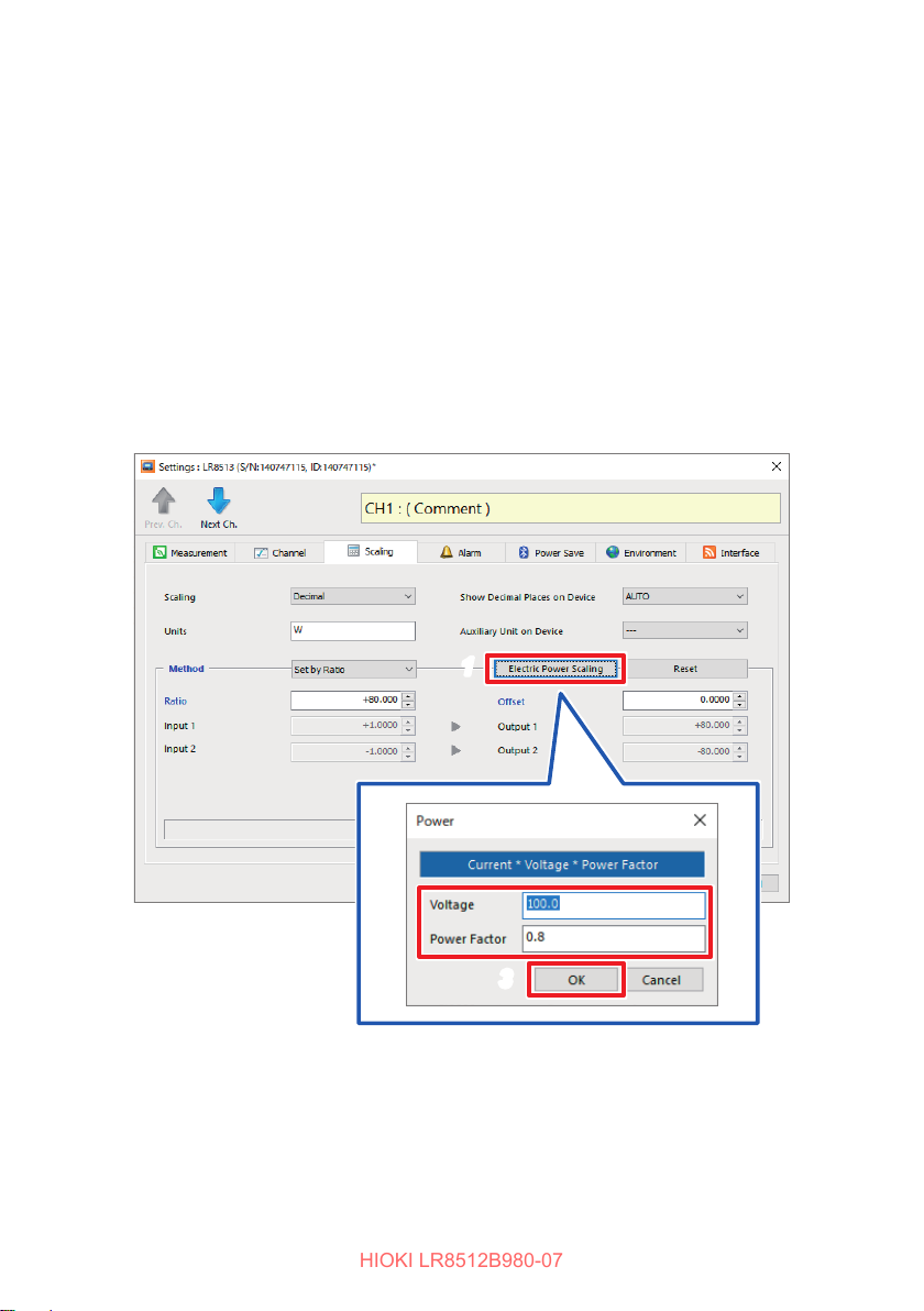
Setting Measurement Conditions
HIOKI LR8512B980-07
Scaling setting for the simple power measurement
With the scaling function, the current value measured by the LR8513 Wireless Clamp
Logger can be measured while it is converted to a power value of single-phase 2-line
wiring.
By entering a V × λ value (V: Voltage, λ : Power factor) in [Ratio] and setting [W]
for [Units] under [Scaling], the power value of single-phase 2-line wiring can be
displayed.
Power value W = Scaling conversion ratio × Current value = V × λ × Current value
You can enter [Voltage] and [Power Factor], which can be displayed by clicking
[ElectricPowerScaling], to congure the scaling settings.
Setting example: Measuring the power of a single-phase 2-wire circuit having a
voltage of 100 V and a power factor λ of 0.8
1
Select [ElectricPower_Scaling].
1
Enter100.0and0.8in[Voltage] and [Power Factor], respectively.
2
Click [OK]
3
2
3
83

Setting Measurement Conditions
HIOKI LR8512B980-07
Setting scaling for integrated measurement
The number of integrated pulses can be converted to a physical quantity (Wh, VA,
etc.) for the object to be measured.
For a pulse output instrument, the physical quantity per pulse or the number of pulses
per basic unit (example: 1 kWh, 1 L, 1 m
3
) is dened.
1
2
3
Select the display format of the scaling value.
1
Settings:
OFF No scaling
Decimal Displays the converted value as a decimal number.
Exponential
Set the unit to be converted (up to 7 single-byte characters).
2
The characters entered are converted to the following symbols.
Set the physical quantity per pulse or the number of pulses per basic unit
3
(Example:1c=1pulse).
The physical quantity per pulse and the number of pulses per basic unit are
linked.
84
^2
^3
~u μ
~c °
~e
Displays the converted value as an index number. Wireless logger
display is in a decimal number only.
2
(Superscript)
3
(Superscript)
ε

Setting Measurement Conditions
HIOKI LR8512B980-07
Scaling setting example
When integrating the number of pulses with a 50,000 pulse/kWh power meter
connected:
Scaling decimal
Unit kWh
1 kWh = 50,000 pulses
When integrating the number of pulses with a 10 L/pulse ow meter connected:
Scaling decimal
Unit L
1 pulse = 10 L
Setting the displayed digit under decimal point
The measurement value is displayed with the decimal point xed to the specied
digit.
Settings:
AUTO
0 Digit/1 Digit
/2 Digit/3 Digit
Displays a 4-digit value (0.000 to ±9,999). The decimal point position is
changed as needed.
The decimal point is xed to the specied digit.
Settingtheauxiliaryunit
The value obtained when the measurement value is multiplied by the constant shown
in the following table is displayed in the wireless logger screen. (The measurement
value is not aected.)
Settings:
μ(micro) ×10
m (milli) ×10
- ×1
k (kilo) ×10
M (mega)
×10
6
3
-3
-6
Reset
The conversion parameter (conversion ratio, oset, input, output) is restored to the
default setting.
85

Setting Measurement Conditions
HIOKI LR8512B980-07
When a temperature measuring channel (the LR8514’s temperature, the LR8515’s
thermocouple) is selected, clicking [Fahrenheit] switches over the scaling setting to
Fahrenheit mode automatically.
[Units]: °F
[Ratio]: 1.8
[Oset]: 32
86

Setting the alarm function (as needed)
HIOKI LR8512B980-07
Make the alarm settings.
Alarm Settings
Allows you to set the alarm function to ON/OFF.
Settings:
OFF Alarm function OFF
ON Alarm function ON
Setting Measurement Conditions
Hold Alarm
Allows you to set the alarm hold function to ON/OFF.
Whether or not to hold the alarm is set.
Settings:
OFF Cancels the alarm when the alarm conditions are no longer met.
ON Holds the alarm.
Composite Condition
Performs logic synthesis for the alarm between channels.
Settings:
OR (Between
channels)
AND (Between
channels)
When the alarm conditions for a channel are met, judges it to be an
alarm.
When the alarm conditions at all channels are met, judges it to be an
alarm.
87

Setting Measurement Conditions
HIOKI LR8512B980-07
Setting the alarm for each channel
Allows you to set the alarm conditions for each channel.
Alarm settings other than logic
Alarm Method
Settings:
OFF Does not perform alarm judgment.
Level When the specied level is reached, judges it to be an alarm.
Window In
Window Out
When a value is inside of the specied upper and lower limit range,
judges it to be an alarm.
When a value is outside of the specied upper and lower limit range,
judges it to be an alarm.
Alarm Level, HIGH/LOW (When Alarm Method is set to Level)
Settings:
HIGH
LOW
Upper Limit, Lower Limit (When Alarm Method is set to Window In, Window
Out)
The judgment level value (upper/lower limit) is set.
88
When a value is more than the specied level value, judges it to be an
alarm.
When a value is less than the specied level value, judges it to be an
alarm.

Alarm settings for logic
HIOKI LR8512B980-07
Bit Pattern
Settings:
OFF Does not perform judgment.
OR
AND
When any of the conditions that are set between channels are met, judges it
to be an alarm.
When all of the conditions that are set between channels are met, judges it
to be an alarm.
Setting Measurement Conditions
X Ignores the signal.
0 When the signal is LOW, judges it to be an alarm.
1 When the signal is HIGH, judges it to be an alarm.
89

Setting Measurement Conditions
HIOKI LR8512B980-07
Setting the power saving function (as needed)
Setting the Bluetooth module power to OFF can save the battery life.
Schedule
The method to turn ON/OFF the Bluetooth module power is set.
Settings:
OFF Does not turn ON/OFF the Bluetooth module power.
EveryDay Turns ON the Bluetooth module power at the specied time.
EveryWeek
EveryMonth
Turns ON the Bluetooth module power at the specied time on the specied
day (Sunday to Saturday).
Turns ON the Bluetooth module power at the specied time on the specied
date (1st to 31st). When the specied date does not exist, it is ignored.
Starting Communication Reception
The clock time to turn ON the Bluetooth module power is set.
Settings:
Allowable
setting range
Continuous Reception Time
The period when the Bluetooth module power is ON is set.
Settings:
Allowable
setting range
• After the power saving function is set, press the power key to turn OFF the
Bluetooth module power.
• When the power saving function is enabled and the Bluetooth module power is
OFF, the Bluetooth symbol (
90
00:00 to 23:59
10 minutes to 12 hours
)
blinks.

Setting Measurement Conditions
HIOKI LR8512B980-07
Setting the environment
Prevent a wrong key operation of the body
A conrmation message can be displayed at the time of measurement start, stop, and
power OFF to prevent operational errors.
Settings:
Does not display a conrmation message.
Displays a conrmation message.
Start Backup
Recording can be resumed when the power is lost due to a power outage, etc. during
recording operation and the power is turned ON again.
Settings:
• Measurement is resumed to the point of the measurement data before a power
outage. The data during the power outage is indicated as [NO DATA]. The saved
data will include values listed in “Handling Data” in the Appendix (p. Appx.6).
• If a power outage continues for an extended period of time (period over
recording interval × 250,000 data), the measurement data prior to the power
outage is discarded and new measurement starts.
• Press the (YES) key to continue the operation.
• Press the
(NO) key to cancel the operation.
• The operation is automatically canceled when the key is
not pressed for 10 seconds.
Does not use the start backup function.
Uses the start backup function.
91

Setting Measurement Conditions
HIOKI LR8512B980-07
Free Run
The measurement value is indicated every 1 second while measurement is stopped.
(the data is not saved in the memory).
The measurement value is saved in the memory every recording interval and
indicated every 1 second regardless of recording interval setting while measuring.
(when the setting of recording interval is less than 1 second, the measurement value
is indicated every recording interval)
Settings:
When the free run function is used, a battery is consumed big because the
measurement is performed every 1 second, so when doing battery drive, please be
careful about a battery remaining amount.
Does not use the free-running function.
Use the free-running function.
Communications
The communications settings of registered wireless loggers are changed.
92
 Loading...