

Hioki LR8432-20 Instruction Manual

LR8432-20
Instruction Manual
HEAT FLOW LOGGER
Jan. 2016 Edition 1
LR8432B980-00 16-01H
EN


Contents
Introduction ..............................................................................1
Confirming Package Contents.................. ..............................2
Safety Information....................................................................4
Operating Precautions............................ .................................8
Chapter 1
Overview ____________________________________15
1.1 Product Overview and Features .............................15
1.2 Measurement Flow ................................... ... ............16
1.3 Names and Functions of Parts ...............................18
1.4 Screen Configurations ................... .........................20
1.5 Basic Operation .......................................................23
Screen Operations ...........................................................23
Starting and Stopping Recording .....................................24
Disabling Key Operations (Key-Lock Function) ...............25
Saving Data ................................................ ......................25
Verifying the Input Level (Level Monitor) ..........................26
i
Contents
1
2
Chapter 2
Measurement Preparations_________________ 27
2.1 Using the Battery Pack (Option) ............................28
Install the Battery Pack ....................................................32
Charge the Battery Pack ..................................................32
2.2 Connecting the AC Adapter ....................................33
2.3 Connecting Measurement Cables to the Instrument
....................................................................................34
Connecting Measurement Leads or Thermocouples
(for voltage or temperature, respectively) ........................36
Connect the Heat Flow Sensor (Heat flow measurement) 37
Connecting the Optional Model 9641 Connection Cable
(for Pulse Signal Input) .....................................................39
2.4 Turning the Power On and Off ...............................40
2.5 Zero Adjustment ......................................................41
LR8432B980-00

ii
Contents
Chapter 3
Setting before Measurement _______________ 43
3.1 Pre-Operation Inspection ....................................... 43
3.2 Operating Flow Overview .......................................44
3.3 Setting Configuration 1 – Recording Settings ..... 48
Specify the Recording Interval .........................................48
Setting the Display Time Base
(horizontal axis magnification, set as needed) .................49
Selecting the Recording Start/stop Method .....................51
Set the Recording Length for Repeated or
One-time Recording .........................................................52
Enable Digital Filtering (noise suppression) (as needed) 52
Automatic Saving .............................................................53
Replacing Removable Storage During Real-Time Saving 55
3.4 Setting Configuration 2 – Input Channel Settings 56
Voltage Measurement Settings ........................................58
Temperature Measurement Settings ...............................59
Heat Flow Measurement Settings ....................................61
Integration (Count) Measurement Settings ......................63
Revolution Measurement Settings ...................................64
3.5 Display Settings ...................................................... 66
Selecting Waveform Display Color ..................................66
Specifying Vertical Display Range by Magnification and
Zero Position (vertical axis expansion/compression) .......66
Specifying the Vertical Display Range by Upper and
Lower Limits (expansion/compression) ............................67
Converting Units (Scaling function) ..................................69
3.6 Entering Comments ................................................ 72
3.7 Viewing All Channel Settings in a List ..................74
Switching Channel Display Settings ................................75
Batch Copying Channel Settings .....................................76
Batch Setting Waveform Display/Hide and
Waveform Color Settings for All Channels .......................77
Initializing Settings (to factory defaults) ...........................77
Aligning Zero Positions on the Grid .................................78
Display Celsius (°C) temperature values as Fahrenheit (°F)
.......................................................................................... 79

Chapter 4
Specifying Criteria for Measurements
(Triggering, Alarm and Timer) ______________81
4.1 Setting Criteria to Start and Stop Recording ........82
Setting the Input Signal Trigger Threshold (Level Trigge r) 83
Setting Lower and Upper Trigger Thresholds
(Window Trigger) ...... ........................................................85
Selecting Trigger Sources and Combinations ..................86
Setting Criteria for Pre-Trigger Recording (Pre-Trig) .......87
4.2 Alarm Output ............................................................88
4.3 Confirming Trigger and Alarm Criteria Settings
(List) ..........................................................................91
4.4 Starting and Stopping Recording by Timer ..........92
4.5 About Recording Operation ...................................94
iii
Contents
3
4
5
Chapter 5
Waveform Analysis__________________________97
5.1 Viewing Waveforms .................................................98
Scrolling Waveforms ........................................................98
Verifying Waveform Display Position ...............................98
Magnifying and Compressing Horizontally .......................99
Viewing Any Waveform Location (Jump Function) ..........99
5.2 Selecting Display Options ....................................100
Displaying Gauges .........................................................100
Displaying Cursor Values ...............................................101
Specifying a Waveform Time Span ................................103
Viewing Input Signals as Numerical Values ...................104
5.3 Inserting Event Marks (Search Function) ............106
Inserting Event Marks While Viewing Waveforms ..........106
Inserting Event Marks Using External Input Signals ......107
Searching Event Marks ..................................................108
Chapter 6
Saving & Loading Data ___________________ 109
6.1 About Saving and Loading Data ..........................109
6.2 Using a CF Card/USB flash drive .........................111
CF Card Insertion & Removal ........................................112
6

iv
Contents
USB flash drive Insertion & Removal .............................112
Formatting a CF Card/USB flash drive ..........................113
6.3 Saving Data ........................................................... 114
Automatic Saving ...........................................................115
Selecting the Manual Saving Method
[Quick Save]/[Select & Save] .........................................116
Saving Waveform Data (with the SAVE Key) ................117
Capturing a Screen Image (With the SAVE Key) ...........118
Saving Numerical Calculation Results
(With the SAVE Key) ......................................................119
Saving Setting Configurations ........................................120
6.4 Loading Data on the Instrument .......................... 121
Loading a Setting Configuration .....................................121
Loading Waveform Data and Screen Images ................122
6.5 Data Management ................................................. 123
Switching removable storage .........................................123
Viewing Folder Contents and the Parent Folder ............124
Deleting Data .................................................................124
Renaming Files and Folders ..........................................125
Copying Data .................................................................126
Sorting Files ...................................................................127
6.6 Transferring Data to a Computer
(USB Drive Mode) .................................................128
Select the USB Drive Mode ........................................... 128
Connecting the USB Cable ............................................129
Chapter 7
Numerical/Waveform Calculations ________ 131
7.1 Performing Numerical Calculation ...................... 131
Key Operation During Setting ........................................133
Calculating values in real time during measurement
(Automatic calculation) ..... ..............................................134
Manual Calculation ........................................................137
Apply Calculations to a Specific Time Span
(Manual Calculation Only) ..............................................138
7.2 Numerical Value C al cu l ati o n Expressions ... ... ... 139
7.3 Performing Waveform Calculation ...................... 141
Key Operation During Setting ........................................141

Setting the Waveform Display Color ..............................144
Setting the Display Format .............................................144
Setting the Display Range in the Vertical Axis Direction
Using Upper/Lower Limit Values ....................................144
7.4 Waveform Calculation Formula ............................145
Chapter 8
System Environment Settings ____________ 147
8.1 Screen and Key Operation Settings ....................148
Using the Auto-Resume Function
(Resume After Power Restoration) ................................148
Adjust Backlight Brightness ............................................148
Enabling and Disabling the Backlight Saver ..................149
Setting the Screen Color Scheme ..................................149
Enabling or Disabling the Beeper ...................................149
Selecting the Horizontal (Time) Axis Display .................150
Selecting the Display Language .....................................150
8.2 CSV File Saving Settings ......................................151
CSV File Data Decimal and Separator Characters ........151
8.3 Making System Settings .......... .............................152
Setting the Date and Time .............................................152
Initializing the Instrument (System Reset) ......................153
Switching the USB mode ...............................................154
Self-Test ...................................................................... ... 155
Chapter 9
External Control __________________________ 157
9.1 Connecting to the External Control Terminals ...157
9.2 External Trigger Input ...........................................159
9.3 External Signal Output (Trigger Output) .............160
9.4 Alarm Signal Output (Alarm Output) ...................162
9.5 Synchronous Measurements with
Multiple Instruments .............................................163
v
Contents
6
7
8
9
10
11
Chapter 10
Specifications_____________________________ 165
Appendix
Index

vi
Contents
Chapter 11
Maintenance and Service _________________ 175
11.1 Troubleshooting ...................................................175
11.2 Cleaning ................................................................. 178
11.3 Disposing of the Instrument ........................ ........ 179
Appendix____________________________________ A1
Appendix 1 Error Messages and Remedial Actions.........A1
Appendix 2 File Naming ......................................................A7
Appendix 3 Text File (CSV) Internal Format......................A9
Appendix 4 Binary File Size Calculation ..........................A10
Appendix 5 List of Default Settings..................................A11
Appendix 6 Maximum Recordable Time ..........................A1 2
Appendix 7 Reference .......................................................A13
Appendix 8 Concerning Noise Countermeasures ..........A14
Appendix 9 Using the Application Program....................A20
Installing Logger Utility ....................................................A22
Installing the USB Driver .................................................A25
Connecting the Instrument to the Computer
with a USB Cable ............................................................A28
Starting and Ending Logger Utility ..................................A31
Uninstalling the Logger Utility .........................................A31
Appendix 10Frequently Asked Questions.......................A32
Installation and Settings ..................................................A32
Triggering ........................................................................ A 34
Measuring ....................................................................... A35
Data Saving .................................................................... A36
Logger Utility ...................................................................A40
Appendix 11Pulse Input Circuit Diagram.........................A41
Appendix 12Heat Flow.......................................................A42
Index ___________________________________ Index 1

Introduction
Thank you for purchasing the HIOKI “Model LR8432-20 Heat Flow
Logger.”
To obtain maximum performance from the instrument, plea se read
this manual carefully, and keep it hand
Registered trademarks
• Windows® is a registered trademark of Microsoft Corporation in
the United States and other countries.
• CompactFlash® is a registered trademark of Sandisk Corporation (USA).
• Microsoft Excel
tion in the United States and other countries.
Introduction
y for future reference.
®
is a registered trademark of Microsoft Corpora-
1
2
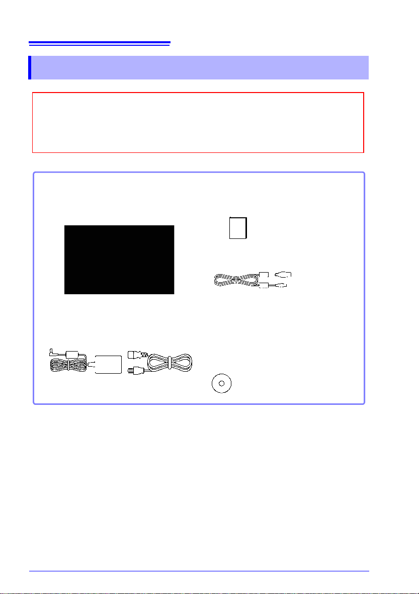
When you receive the instrument, inspect it carefully to ensure tha t no damage
occurred during shipping. In particular, check the accessories, panel switches,
and connectors. If damage is evident, or if it fails to operate according to the
specifications, contact your authorized Hioki distributor or reseller.
Confirm that these contents are provided.
Model LR8432-20 .........................1
Heat Flow Logger
Accessories:
Model Z1005 AC Adapter............ 1
with supplied power cord
(p. 33)
Measurement Guide....................1
USB Cable....................................1
CD.................................................1
• Instruction Manual (PDF)
(This document)
• Logger Utility Instruction Manual (PDF)
• Logger Utility (Data acquisition
application program)
(p. A28)
The latest version can be
downloaded from our web site.
Confirming Package Contents
Confirming Package Contents
About options:
Contact your authorized Hioki distributor or reseller for details.
Model 9780 Battery Pack
Model Z1005 AC Adapter
Model 9641 Connection Cable (for pulse inputs)
Model 9782 Carrying Case
Model 9812 Soft Case
Model 9728 PC Card 512M
Model 9729 PC Card 1G
Model 9830 PC Card 2G
Model 9809 Protection Sheet
Z2012 Heat Flow Sensor
Z2013 Heat Flow Sensor
Z2014 Heat Flow Sensor
Z2015 Heat Flow Sensor
Z2016 Heat Flow Sensor
Z2017 Heat Flow Sensor
Z5008 Thermally Conductive
Tape

3
Confirming Package Contents
Applying any excessive force to the Heat Flow Sensor can
damage the sensor. When transporting the Heat Flow Sensor
in a case, store the sensor in the pocket of the 9782 Carrying
Case. Do not store the Heat Flow Sensor in the 9812 Soft
Case.
4
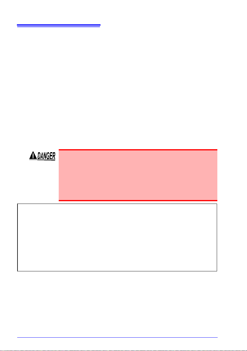
Safety Information
Safety Information
This instrument is designed to conform to IEC 61010 Safety Standards, and has been thoroughly tested for safety prior to shipment.
However, usi
ual may negate the provided safety features.
Before using the instrument, be certain to carefully read the following safety notes:
Mishandling during use could result in injury or death, as well
as damage to the instrument. Be cer tain that you understand
the instructions and precaution s in the manual before use.
With regard to the electricity supply, there are risks of electric
shock, heat generation, fire, and arc flash due to short circuits. If persons unfamiliar with electricity measuring instrument are to use the instru ment, another person fa miliar with
such instr
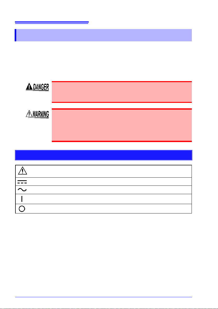
Safety Symbols
ng the instrument in a way not described in this man-
uments must supervise operations.
Indicates cautions and hazards. When the symbol is printed on the instrument,
refer to a corresponding topic in the Instruction Manual.
Indicates DC (Direct Current).
Indicates AC (Alternating Current).
Indicates the ON side of the power switch.
Indicates the OFF side of the power switch.
Safety Information
Ni-MH
Notation
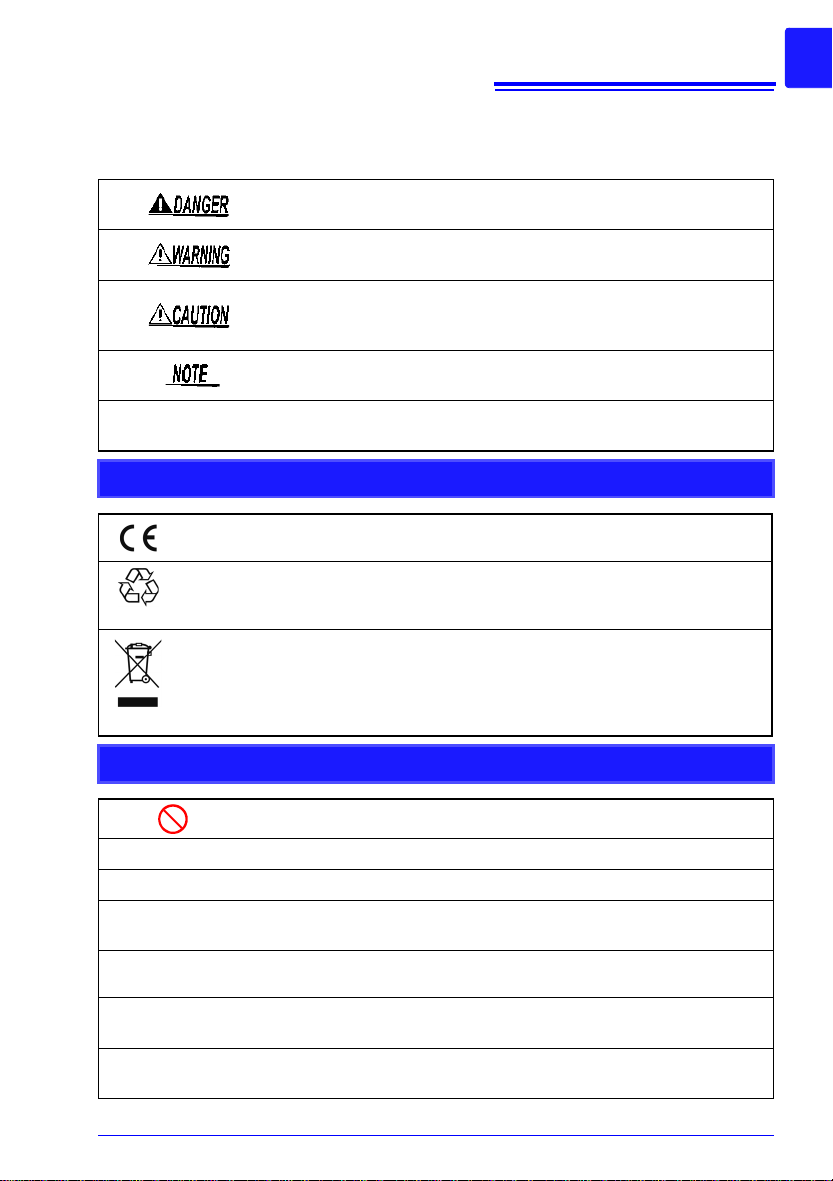
In this document, the risk seriousness and the hazard levels are classified as follows.
Indicates an imminently hazardous situation that will result in death or
serious injury to the operator.
Indicates a potentially hazardous situation that may result in death or
serious injury to the operator.
Indicates a potentially hazardous situation that may result in minor or
moderate injury to the operator or damage to the instrument or malfunction.
Indicates advisory items related to performance or correct operation of
the instr
ument.
IMPORTANT
Indicates information related to the operation of the instrument or
maintenance tasks with which the operators must be fully familiar.
Symbols for Various Standards
This symbol indicates that the product conforms to regulations set out by the
EC Directive.
This is a recycle mark established under the Resource Recycling Promotion
Law
(only f
or Japan).
5
WEEE marking:
This symbol indicates that the electrical and electronic appliance is put on the
EU
mark
required to display it on the appliance under Article 11.2 of Directive 2002/96/
EC (WEEE).
et after August 13, 2005, and producers of the Member States are
Other Symbols
Indicates the prohibited action.
(p. #)
∗
[ ]
SET
(Bold characters)
Unless otherwise specified, “Windows
Windows
Click: Press and quickly release the left button of the mouse.
Double click: Quickly click the left button of the mouse twice.
®
7, Windows® 8, or Windows® 10.
Indicates the location of reference information.
Indicates that descriptive information is provided below.
The names of setting objects and buttons on the screen are indicated
by square brackets [ ].
Bold characters within the text indicate operating key labels.
®
” represents Windows® XP, Windows Vist a®,
6
Safety Information
Accuracy
We define measurement tolerances in terms of f.s. (full scale), rdg. (reading) and
dgt. (digit) values, with the following meanings:
f.s. (maximum display value or scale length)
The maximum displayable value or scale length. This is usually the name of the currently selected range.
Example: For the 1 V range, f.s. = 1 V
rdg. (reading or displayed value)
The value currently being measured and indicated on the measuring instrument.
dgt. (resolution)
The smallest displayable unit on a digital measuring instrument, i.e., the input value
that causes the digital display to show a “1” as the least-significant digit.
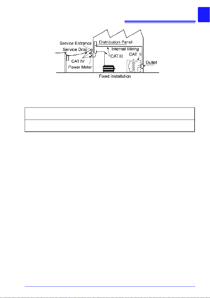
Measurement categ o ries
To ensure safe operation of measurement instruments, IEC 61010
establishes safety standards for various electrical environments, categorized as CAT II to CAT IV, and called measurement categories.
• Using a measuring instrument in an environment designated with a higher-n umbered category tha n that for which
the instrume
and must be carefully avoided.
• Never use a measuring instrument that lacks category labeling in a CAT II to CAT IV measurement environment. Doing
so could result in a serious accident.
nt is rated could result in a severe accident,
CAT II
CAT III
CAT IV
When directly measuring the electrical outlet receptacl es of the prim ary electrical circuits in equipment connected to an AC electrical outlet by a power
cord (por
When measuring the primary electrical circuits of heavy equipment (fixed
install
the distribution panel to outlets
When measuring the circuit from the service drop to the service entrance,
and to the power meter and primary overcurrent protection device (distribution panel)
table tools, household appliances, etc.)
ations) connected directly to the distribution panel, and feeders from
Safety Information
Difference between “Measurement” and “Recording”
The measurement and recording processes are distinguished as follows for the purposes of
these instructions.
7
Measurement:
Recording:
Measured data (data acquired in internal memory) is erased whenever a new measurement
start
s. To retain data, always record (save) it.
The acquisition of input values into the instrument’s internal memory or to
a PC vi
a communications.
Storing measurement data on a CF card, USB flash drive or on a PC via
dat
a commu
nication.

8
Operating Precautions
Operating Precautions
Follow these precautions to ensure safe operation and to obtain the full benefits of
the various functions.
Before Use
• Before using the instrument for the first time, verify that it operates normal
ensure that no damage occurred during storage or shipping. If you find any damage, contact your authorized Hioki distributor or reseller.
• Before using the instrument, make sure that the insulation on the cables is undamaged and that no bare conductors are improperly exposed. Using the instrument in
such c
onditions could cause an electric shock, so contact your authorized Hioki
distributor or reseller for replacements.
ly to
Instrument Installation
Installation environment
• This instrument is not drip-proof. Install the instrument with the
measurement cables hanging lower than the instrument to prevent water or other fluid from entering the instrument through the
measurement cables and terminal block.
• The maximum operating (ambient) temperature for the LR843220 is 40°C. D
ments.
• Correct measurement may be impossible in the presence of
strong magnetic fields, such as near transformers and high-current conductors, or in the presence of strong electromagneti
fields such as near radio transmitters.
• If liquid enters the enclosure through an air vent or other opening, it
may damage the instrument’s internal circuitry . Exercise caution concerning the surrounding environment when installing the instrument.
o not attempt to use in higher temperature environ-
c
Do not place the instrument on an unstable table or an inclined
place. Dropping or knocking down the instrument can cause injury
or damage to the instrument.
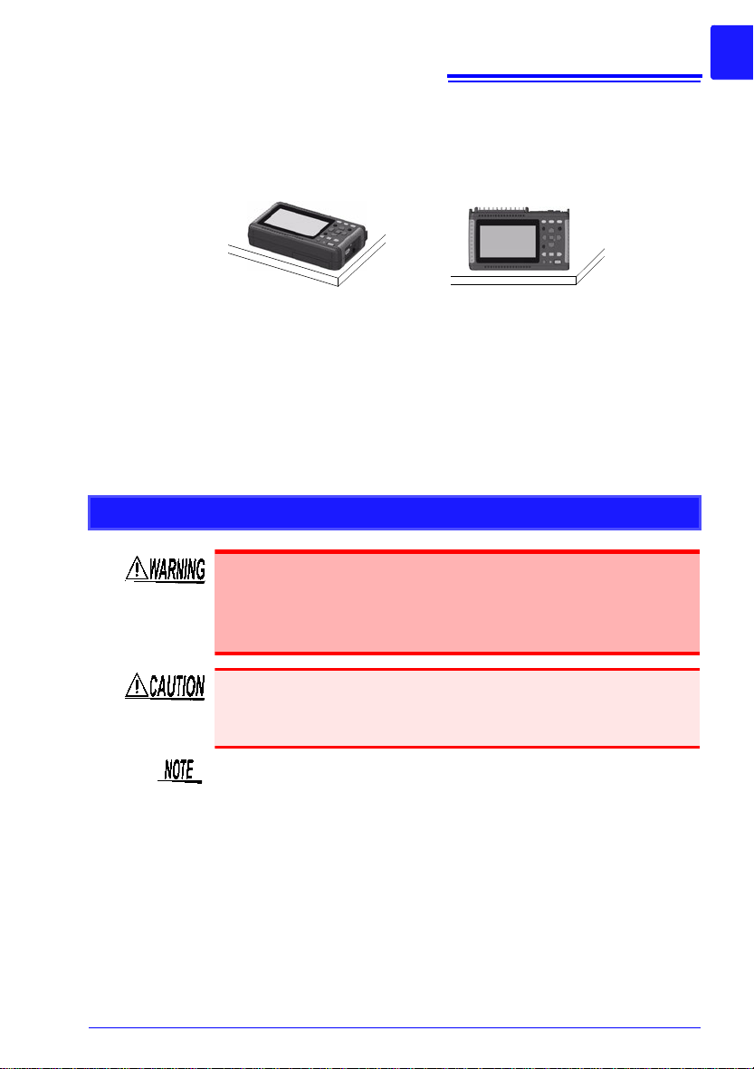
Installation Precautions
Horizontal placement Upright placement
• If the instrument is used in any state other than the following, the
measurement accuracy may not satisfy the device specifications.
• Leave sufficient space around the ventilation holes and install the
instrument with the holes unobstructed.
• Avoid temperature changes around the terminal block. Especially
avoid di
vent. Thermocoup le inp ut s are pr one to me asure ment error s.
• When the instrument is moved to a location with significantly different ambient temperature, allow at least 30 minutes for thermal
equalization be
rected airflow such as from an electric fan or air conditioner
Handling the Instrument
9
Operating Precautions
fore measuring.
• Do not allow the in strum ent to g et we t, and do no t take measurements with wet hands. This may cause an electric shock.
• Do not attempt to modify, disassemble or repair the instrument; as fire, electric shock and injury could result.
To avoid damage to the instrument, protect it from physical shock
when transporting and handling. Be especially careful to avoid
physical shock from dropping.
This instrument may cause interference if used in residential
areas. Such use must be avoided unless the user takes special
measures to reduce electromagnetic emissions to prevent interfer
ence to the reception of radio and television broadcasts.
-

10
Operating Precautions
Handling the Cords and Cables
The cable is hardened under the 0°C or colder environment. Do
not bend or pull it to avoid tearing its shield or cutting cable.
Before Turning Power On
Using the Battery Pack
• For battery operation, use only the HIOKI Model 9780 Battery
Pack. We do not take any responsibility for accidents or
damage related to the use of any other batteries.
Refer to “2.1 Using the Battery Pack (Option)” (p. 28).
Using the AC Adapter
• Use only the supplied Model Z1005 AC Adapter. AC adapter
input voltage range is 100 V to 240 VAC at 50 Hz/60 Hz. To
avoid electrical hazards and dam age to the instrument, do
not apply voltage outside of this range.
• Tur n the instrument off bef ore connec ting the AC adapter to
th
e instrum
• T o avoid electrical accidents and to maintain the safety specifications of this instrument, connect the power cord provided only to a 3-contact (two-conductor + ground) outlet.
• Use only the designated power cord with this instrument.
Use of othe
• Before turning the instrument on, make sure the supply voltage matches that indicated on its power connector. Connection to an improper supply voltage may damage the
instrument and present an electr ical hazard.
ent and to AC power.
r power cords may cause fire.
• Do not connect the supply voltage improperly. Doing so may
damage the instrument’s internal circuitry.
• Avoid using an uninterruptible power supply (UPS) or DC/AC
inverter with rectangular wave or pseudo-sine-wave output to
power the instrument. Doing so may damage the instrument.
• When the power is turned off, do not apply voltage or current to
the terminals.
Doing so may damage the instrument.
• After use, always turn OFF the power.
IMPORTANT
Select Hioki 9641 Connection Cable for use as a cable for the
pulse input connector.
• Brief power interruptions of 40 ms or less will not cause this
instrument to malfunction. However, Longer interruptions may
cause the instrument to shut itself off, so consider local power
conditions before installing, as appropriate.
• To ensure that recording is not interrupted by power outages, you
can use the Z1005 AC Adapter and 9780 Battery Pack tog ether.
About Inputs and Measurement
• Do not use the instrument with circui ts that exceed its ratings or specifications. Doing so may cause it to become
hot, resulting in bodily injury.
• To av oid electrical hazards and damage to the instrument ,
do not apply voltage exceeding the rated maxim um to the
input terminals.
• The maximum input voltage (and the maximum r ated voltage to earth) for the analog input terminals is 30 V AC rms
(or 60 V
may be damaged and perso nal injury or death co uld occur,
so do not attempt measurement.
• Do not leave the instrument connected to test objects in environments where a voltage surge m ight exceed the dielec tric
wi
instrument, bodily injury or fatal accident.
• Channels are insulated by semiconductor relays. When a
voltage beyond the
channels, the semiconductor relay may short circuit. Please
ensure that a voltage beyond specification, especially a
surge such as a lightning, is never applied. When an abn ormal measurement value is observed, please contact your
authorized Hioki distributor or reseller for inspection.
DC). If these limits are exceeded, the instrument
nd voltage. Doing so could result in damage to the
thsta
11
Operating Precautions
specification is applied between the
The waveform for an open channel may sometimes appear to b e
influenced by the signals of the other channels being measured. If
you do not like this, please set the waveform display of the open
channel to OFF or short-circuit the input terminals of the open
channel by connecting the positive and negative terminal.

12
Operating Precautions
CD Handling
CD precautions
• Exercise care to keep the recorded side of discs free of dirt and
scratches. When writing text on a disc’s label, use a pen or
marker with a soft tip.
• Keep discs inside a protective case and do not expose to direct
sunlight, high temperature, or h
• Hioki is not liable for any issues your computer system experiences in the course of using this disc.”
Using a CF Card/USB flash drive
• Inserting a CF card/USB flas h drive upside down, backwards or i n the
wrong direction may damage the CF card, USB flash drive, or instrument.
• Never eject a CF card /USB flash drive while measuring or when the
instrum
ent is or accessing the card. Data on the CF card/USB flash
drive may be destroyed. (The CF icon/USB flash drive icon at the
lower right is red while the card is being accessed.)
• Do not transport the instrument while a USB flash drive is connected.
D
amage cou
• As the CF card/USB flash drive is sensitive to static elect ricity, damage
to the CF card/USB flash drive or wrong operations by the instrument
may occur due to static electricity. Please be careful when handling it.
• With some USB flash drives, the instrument may not start up if power
is tur
power on first, and then insert the USB flash drive. It is recommended
to try out operation with a USB flash drive before starting to use it for
actual measurements.
ld result.
ned on while the USB flash drive is inserted. In such a case, turn
igh humidity.
13
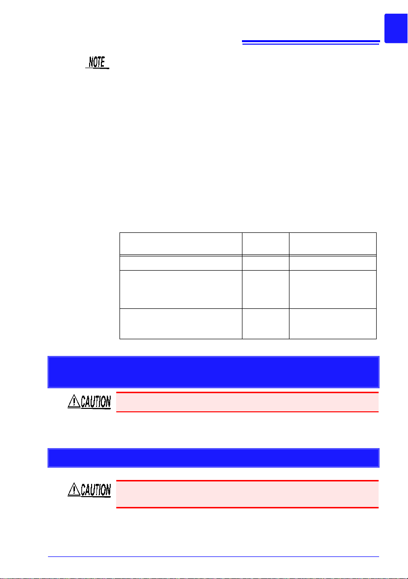
USB method of use
Connector
used
[System] screen USB
mode setting
Use a USB flash drive. Type A USB Memory (Default)
Communicate with the LR8432-20
and initiate measurem ent using the
Logger Utility software from a computer (using a USB ca bl e).
Type B USB Communication
Read files o n a CF card that is connected to the LR8432-20 from a
computer (using a USB cable) .
Type B USB Drive
Operating Precautions
• The Flash memory in a CF card/USB flash drive has a limited operating life. After long-term usage, data storage and retrieval beco me difficult. In this case, replace the CF card/USB flash drive with a new one.
• We cannot provide compensation for data loss in a CF card/USB flash
drive,
regardless of content or cause of the damage. Data is also cleared
from memory if a long time passes after measuring. Always maintain a
backup of important data stored on a CF card/USB flash drive.
• Although real-time saving to USB flash drive is supported, a CF card is
r
ecommend
when using storage media other than a Hioki-sp ecified C F card optio n.
• Use a USB flash drive whose continuous current consumption does not
exceed 300 m
Power” under the USB flash drive self -test on the [System] screen.)
• Depending on how USB is used, the USB connector and i nst r um ent settings may vary as shown in the chart below.
• The three USB methods of use described in the chart below involve
exclusive set
ed for data preservat ion. Perf ormance can not be gu aranteed
A (peak 500 mA). (The peak value is displayed as “Max
tings and cannot be used simultaneou sly.
Heat Flow Sensor (Models Z2012, Z2013, Z2014, Z2015, Z2016,
Z2017)
Do not subject the Heat Flow Sensor to excessive force.
Refer to the instruction manual included with the Heat Flow Sensor
for details.
Thermally Conductive Tape Z5008
Stop using double-sided Thermally Conductive Tape immediately
if it touches the human body and causes an abnormality.

14
Operating Precautions
15
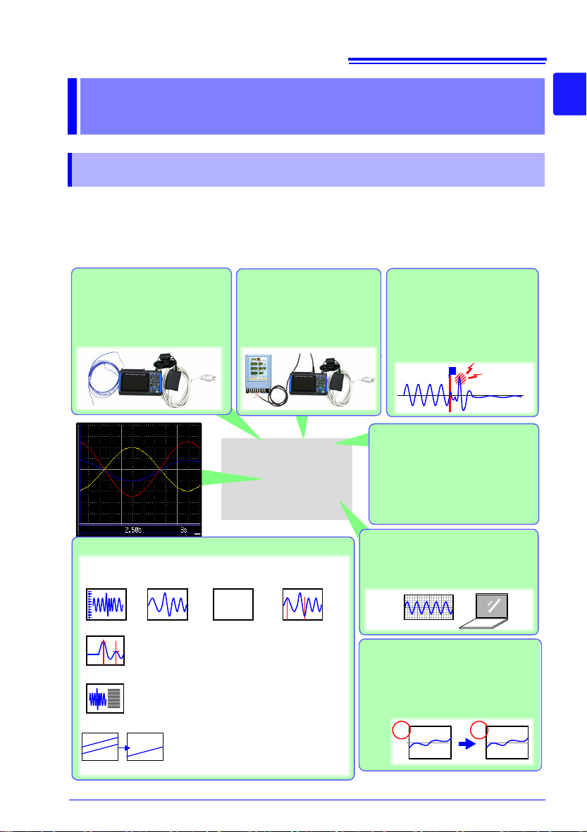
Record anomalies
Abnormal events ca n be analyzed by recording with the
trigger function (p. 81)
Use the alarm function to ou tput signals when anomalies
occur (p. 88).
Measurement data and
setting configurations are
stored, read and managed
as data files
Measuremen t d ata c a n be s to re d
to and read from a CF card or
USB flash drive (p. 109).
Waveform analysis
mV A
Cursor Measurements (p. 101)
Using the A/B cursors, values at cursor locations
on waveforms and the tim e at trigger positions
can be displayed.
Performs seven calculation types, including maximum and average values.
Numerical Calculations (p. 131)
Acquire pulse signals
Measure integrated pulses
or revolutions from sensors
and pulse output devices
such as watt-hour meters.
Gauge display (p. 100)
Zoom in/out
(p. 99)
Numerical display
(p. 104)
Analysis on a PC
Monitor and anal yze m easu re me nt
data with the supplied application
program (p. A20).
Event search
(p. 106)
T
Display in converted units
Using the scaling function, in put values can be displayed in units of the
actual physical quantity being measured, such as current or flow volume (p. 69).
Observe voltage fluctuations,
temperature, and heat flow
Just connect measurement leads,
thermocouples, or heat flow sensors to perform measurement as
needed.
Waveform Calculations (p. 101)
Performs five types of calculations, including four arit hm etic operations and a
moving average, a nd disp lays results in
a waveform format.
CH1
CH2
W1
123.4V
1 2
A
B
1.1 Product Overview and Features
Overview Chapter 1
1.1 Product Overview and Features
The Hioki LR8432-20 Heat Flow Logger is a compact, lightweight, easy-tooperate waveform recorder. It can run on batteries, and can be quickly
deployed when a power anomaly occurs.
Measurement data can be m onitored, subjected t o calculations and ana lyzed
o
n a perso
nal computer using the sup plied application program.
1
Chapter 1 Overview
3
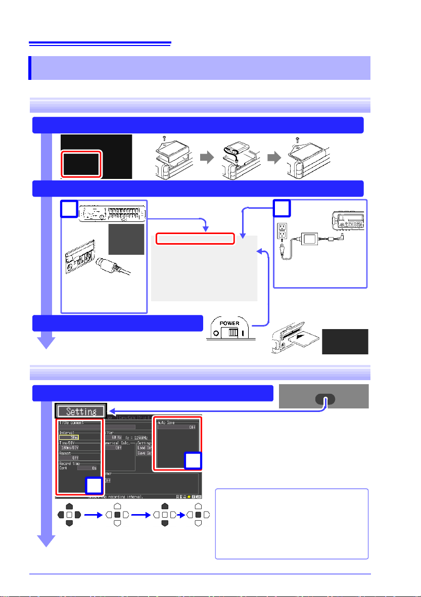
16
To save data, insert a
CF card or USB flash
drive. (p. 112)
AC adapter
connection (p. 33)
Install the Battery Pack (option) (p. 28)
Connect to the Model LR8432-20 (p. 27), and Set Up (p. 9)
Turn the Power On (p. 40)
Measurement
cables connections
(p. 34)
1
2
Configure Recording Settings (p. 44)
Using a previously saved
setting configuration
Reload a previously stored setting con figuration from Model LR8432-20
memory or a CF card or USB flash
drive, and measure (p. 121)
Set the data acquisition (recording) interval, and recording length (time span).
Select the type of measurement data to
save when automatically saving to a CF
card or USB flash drive.
Remaining data stored in the instrument
can be saved when finished measuring.
Move to a
setting item
Open the
setting options
Select Apply
1
2
1.2 Measurement Flow
1.2 Measurement Flow
Installing, Connecting and Turning On
Settings
1.2 Measurement Flow
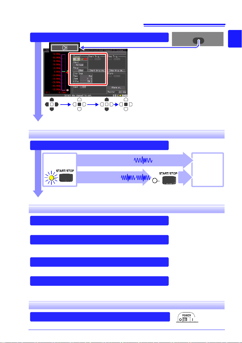
Configure Input Channe ls (p. 44)
Select input channels, and set input types
and measurement ranges.
Make other settings as desired.
Move to a
setting item
Open the
setting options
Select Apply
Press the START/STOP Key (p. 24)
Record once, and stop.
[Repeat]: Off
Stop
Measurement
Start
Measurement
When recording using the trigger function, recording occurs only
when the input waveform satisfies specified trigger criteria.
Record repeatedly.
[Repeat]: On
(default setting)
View Measurement Data (p. 97)
Waveforms can be zoomed and numerical values confirmed.
Save Data (p. 109)
Measurement data, waveform data, screen images and numerical calculation
results can be saved.
Calculate (p. 131)
Numerical measurement data can be applied to calculations.
View on a Computer (p. A20)
Analyze recorded data using the supplied application program.
Turn the Instrument O ff (p. 40)
Sta rting and Stopping Measurement
17
1
Chapter 1 Overview
3
Data Analysis
When Finished
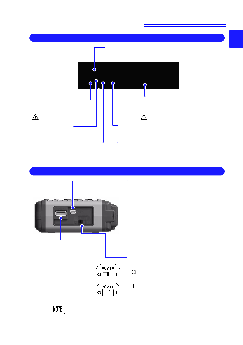
18
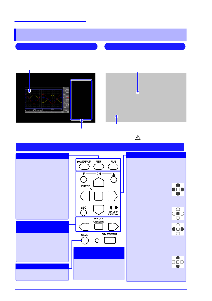
Front Panel
Operating Keys
Rear Panel
Battery Compartment (p. 28)
The optional Model 9780 Battery Pack is
installed here.[ :(p. 10)]
Manufacturer’s Serial No.
Shows the serial number.
Do not remove this label, as it is required
for product support.
Display Screen (p. 97)
4.3-inch TFT color LCD
Screen Configurations (p. 20)
WAVE/DATA
Selects among waveform
screen displays (p. 20).
SET
Displays the Settings
screens, and switches
among the screen tabs
with each press (p. 22).
FILE
Displays file information
(p. 21).
CH/
Select channels.
ESC
Cancels changes to settings.
Cursor Keys
Moves the position of
the cursor (blinking
selection) on the
screen.
ENTER
Accepts displayed
settings.
KEY LOCK
Disables keypad operations. Press and
hold the left and right
cursor keys simultaneously for
three seconds to lock and unlock the keys.
(Zero Adjust )
Performs zero adjustment. Press the up
and down keys simultaneously to execute (p. 41).
Press to save data manually (p. 114).
Press the center key to
select waveform scrolling
or A/B cursor movement,
then press the left and
right cursor keys to scroll
or move (p. 23).
Setup and display
Saving operations
Scroll waveforms and
read cursor values
Choose a screen
Start and stop measurement. The LED at the left
lights green while measuring (p. 24).
Start and stop
measurement
Operating Keys
1.3 Names and Functions of Parts
1.3 Names and Functions of Parts
19
Top Panel
AC Adapter Socket
Connect the supplied Model
Z1005 AC Adapter (p. 33).
[ :(p. 10)]
CF Card Slot
Insert an optional CF card. (p. 111)
Analog Input Terminals
Connect measurement leads for voltage measurement, and thermocouples for temperature
(p. 34).[ :(p. 11)]
CHARGE LED
This LED lights when the
battery is charging (p. 32).
Pulse Input Connector
Connect an optional 9641 cable (p. 39) .
External Control Terminals
Control signals can be received from and
output to external devices (p. 157).
Right Side
POWER Switch
Turns the instrument on and off (p. 40)
Power Off
Power On
USB Port
(USB 2.0 mini-B receptacle)
• Using the included Logger Utility application software, you can monitor measurement data on the computer and transfer
settings to the instrument. (p. A28) (To
use, set the USB mode on the [System]
screen to [USB Comm.].)
• You can transfer data on the instrument’s
CF card to a computer. (p. 128) (To use,
set the USB mode on the [System]
screen to [USB Drive].)
USB flash drive Slot
(Type A USB 2.0
receptacle)
Used to save data to a USB
flash drive. (p. 112) (To
use, set the USB mode on
the [System] screen to
[USB Memory].)
1.3 Names and Functions o f Parts
1
Chapter 1 Overview
3
The [USB Memory ], [USB Comm.], and [USB Drive] US B mo d e
settings are exclusive and cannot be used simultaneously.
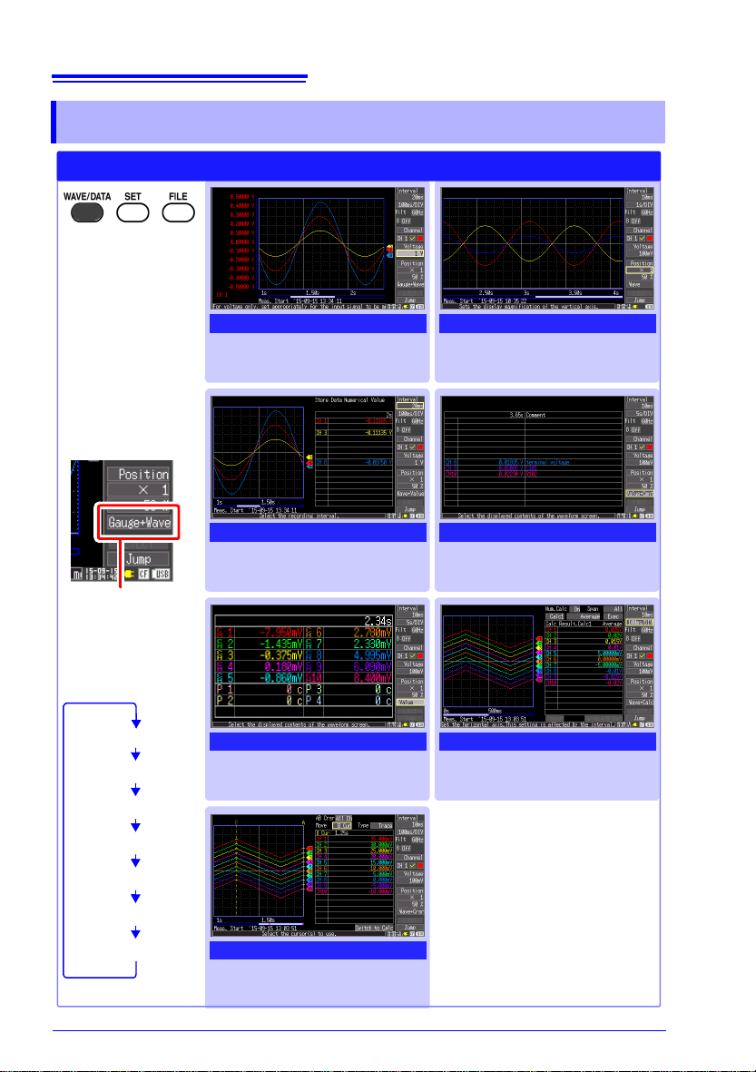
20
Selects between
seven display
types.
The screen switches
each time you press
the key.
Operational information is displayed
along the bottom of
the screen.
[Wave] Screen
Measurement data is displayed
as waveforms (p. 97).
[Value+Cmnt] Screen
Measurement data is displayed
as numerical values with comments (p. 104).
[Wave+Calc] Screen
Measurement data is displayed
as waveforms with calculation
results (p. 137).
[Gauge+Wave] Screen
Measurement data is displayed
as waveforms with gauges (p.
100).
[Wave+Value] Screen
Measurement data is displayed
as waveforms and numerical
values (p. 104).
[Value] Screen
Measurement data is displayed
as numerical values (p. 104).
[Wave+Crsr] Screen
Measurement data is displayed
as waveforms with cursor values (p. 101).
Waveform/Numerical Screens
Selection is also
available from the
name of the current
screen displayed
near the bottom right
[Gauge+Wave]
[Wave]
[Wave+Value]
[Value+Cmnt]
[Value]
[Wave+Calc]
[Wave+Crsr]
1.4 Screen Configurations
1.4 Screen Configurations
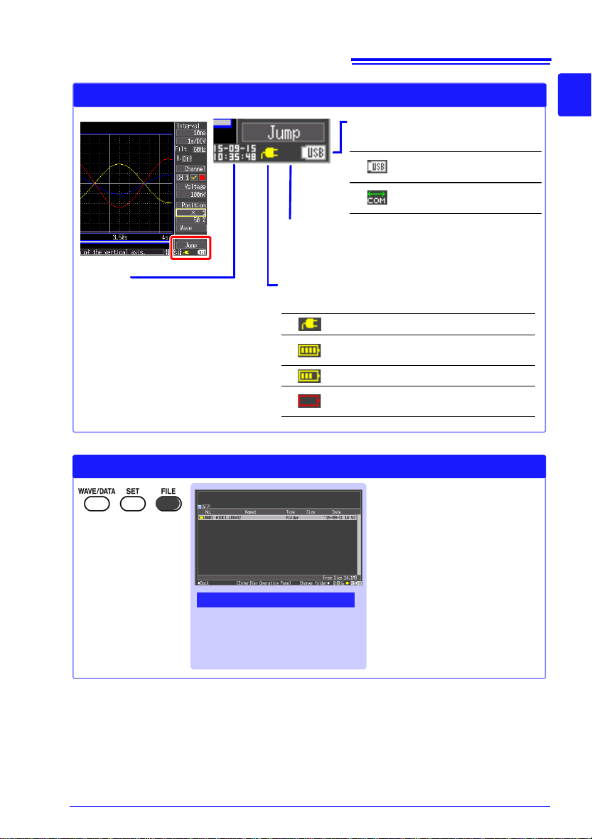
21
Icons (Commonly used on all of the screens)
Clock
“Setting the Date and Time”
(p. 152).
Power source indicator
Indicates the instrument’s power source.
AC adapter operation
Battery pack operation
(
Fully charged battery pack)
Battery pack operation
Battery pack operation
(Low battery indicator)
CF card
Displayed when a CF card is inserted.
The icon appears red when accessing the card.
USB source indicator
Indicates the USB status.
USB flash drive inserted
in USB Memory mode.
Operating in USB
Communication mode.
File Screen
View and manage files on the
CF card or USB flash drive
(p. 109).
File Screen
Operational information is displayed
along the bottom of
the screen.
1.4 Screen Configurations
1
Chapter 1 Overview
3
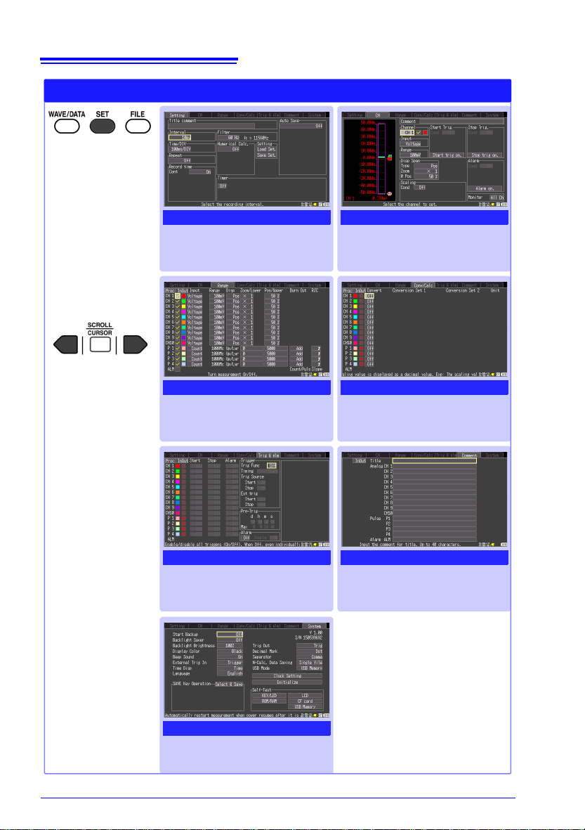
22
[CH] Screen
Make input channel settings
while viewing the monitor display (p. 56).
[Conv/Calc] Screen
Make these settings to convert
measured values to arbitrary
units for display (p. 69).
[Comment] Screen
Enter channel comments
(p. 72)
[Setting] Screen
[Range] Screen
Make settings while viewing all
channel settings (p. 74).
[Trig & Alm] Screen
Recording criteria (triggering)
and warning sounds can be set
for each channel (p. 81).
[System] Screen
Configure the system environment (p. 147).
Settings Screens
Press the left/right
cursor keys to select between the
Settings screens.
Selects between
seven display
types.
The screen switches each time you
press the key.
Operational information is displayed
along the bottom of
the screen.
Make settings for recording (p .
48). Set numerical calculation,
auto-saving and timers.
1.4 Screen Configurations
 Loading...