

Hioki LR8431-20 Instruction Manual

LR8431-20
Instruction Manual
MEMORY HiLOGGER
Aug. 2015 Revised edition 3
LR8431B980-03 15-08H
EN


Contents
Introduction ..............................................................................1
Confirming Package Contents................................................2
Safety Information....................................................................3
Operating Precautions.............................................................6
Chapter 1
Overview ____________________________________13
1.1 Product Overview and Features .............................13
1.2 Measurement Flow ........... .......................................14
1.3 Names and Functions of Parts ...............................16
1.4 Screen Configurations ............................................18
1.5 Basic Operation .......................................................21
Screen Operations ...........................................................21
Starting and Stopping Recording .....................................22
Disabling Key Operations (Key-Lock Function) ...............23
Saving Data ......................................................................23
Verifying the Input Level (Level Monitor) ..........................24
i
Contents
1
2
Chapter 2
Measurement Preparations_________________25
2.1 Using the Battery Pack (Option) ............................26
Install the Battery Pack ....................................................29
Charge the Battery Pack ..................................................29
2.2 Connecting the AC Adapter ....................................30
2.3 Connecting Measurement Cables to the Memory
HiLogger ...................................................................31
Connecting Measurement Leads or Thermocouples
(for voltage or temperature, respectively) ........................32
Connecting the Optional Model 9641 Connection Cable
(for Pulse Signal Input) .....................................................33
2.4 Turning the Power On and Off ...............................34
2.5 Zero Adjustment ......................................................35
LR8431B980-03

ii
Contents
Chapter 3
Setting before Measurement_______________ 37
3.1 Pre-Operation Inspection ....................................... 37
3.2 Operating Flow Overview ........................ ............... 38
3.3 Setting Configuration 1 – Recording Settings ..... 42
Specify the Recording Interval .........................................42
Setting the Display Time Base (horizontal axis
magnification,set as needed) ...........................................43
Selecting the Recording Start/stop Method .....................44
Set the Recording Length for Repeated or One-time
Recording ............................................................. ............45
Enable Digital Filtering (noise suppression) (as needed) 45
Automatic Saving .............................................................46
Replacing Removable Storage During Real-Time Saving 48
3.4 Setting Configuration 2 – Input Channel Settings 49
Voltage Measurement Settings ........................................50
Temperature Measurement Settings ...............................51
Integration (Count) Measurement Settings ......................53
Revolution Measurement Settings ...................................54
3.5 Display Settings ...................................................... 56
Selecting Waveform Display Color ..................................56
Specifying Vertical Display Range by Magnification and
Zero Position (vertical axis expansion/compression) .......56
Specifying the Vertical Display Range by Upper and
Lower Limits (expansion/compression) ............................57
Converting Units (Scaling function) ...................... ........ ....58
3.6 Entering Comments ................................................ 60
3.7 Viewing All Channel Settings in a List .................. 62
Batch Copying Channel Settings .....................................63
Batch Setting Waveform Display/Hide and Waveform
Color Settings for All Channels ........................................63
Initializing Settings (to factory defaults) ...........................64
Aligning Zero Positions on the Grid .................................64
Display Celsius (°C) temperature values as
Fahrenheit (°F) .................................................................65

Chapter 4
Specifying Criteria for Measurements
(Triggering, Alarm and Timer) ______________67
4.1 Setting Criteria to Start and Stop Recording ........68
Setting the Input Signal Trigger Threshold (Level Trigger) 69
Setting Lower and Upper Trigger Thresholds
(Window Trigger) ..............................................................70
Selecting Trigger Sources and Combinations ..................71
Setting Criteria for Pre-Trigger Recording (Pre-Trig) .......72
4.2 Alarm Output ............................................................73
4.3 Confirming Trigger and Alarm Criteria Settings
(List) ......................... .......................... ....................... 75
4.4 Starting and Stopping Recording by Timer ..........76
4.5 About Recording Operation ...................................78
iii
Contents
3
4
5
Chapter 5
Waveform Analysis__________________________81
5.1 Viewing Waveforms .................................................82
Scrolling Waveforms ........................................................82
Verifying Waveform Display Position ...............................82
Magnifying and Compressing Horizontally .......................83
Viewing Any Waveform Location (Jump Function) ..........83
5.2 Selecting Display Options ......................................84
Displaying Gauges ...........................................................84
Displaying Cursor Values .................................................84
Specifying a Waveform Time Span ..................................86
Viewing Input Signals as Numerical Values .....................87
5.3 Inserting Event Marks (Search Function) ..............88
Inserting Event Marks While Viewing Waveforms ............88
Inserting Event Marks Using External Input Signals ........89
Searching Event Marks ....................................................90
Chapter 6
Saving & Loading Data _____________________91
6.1 About Saving and Loading Data ............................91
6.2 Using a CF Card/USB flash drive ...........................93
CF Card Insertion & Removal ..........................................94
6

iv
Contents
USB flash drive Insertion & Removal ...............................94
Formatting a CF Card/USB flash drive ............................95
6.3 Saving Data ............................................................. 96
Automatic Saving .............................................................97
Selecting the Manual Saving Method
[Quick Save]/[Select & Save] ...........................................98
Saving Waveform Data (with the SAVE Key) ..................99
Capturing a Screen Image (With the SAVE Key) ...........100
Saving Numerical Calculation Results
(With the SAVE Key) ......................................................101
Saving Setting Configurations ........................................102
6.4 Loading Data on the Memory HiLogger .............. 103
Loading a Setting Configuration .....................................103
Loading Waveform Data and Screen Images ................104
6.5 Data Management ................................................. 105
Switching removable storage .........................................105
Viewing Folder Contents and the Parent Folder ............106
Deleting Data .................................................................106
Renaming Files and Folders ..........................................107
Copying Data .................................................................108
Sorting Files ...................................................................109
6.6 Transferring Data to a Computer
(USB Drive Mode) ............................... .................. 110
Select the USB Drive Mode ...........................................110
Connecting the USB Cable ............................................111
Chapter 7
Numerical Calculations ___________________113
7.1 Calculation Methods ........ ... .................................. 113
Auto Calculation .............................................................114
Manual Calculation ........................................................115
Apply Calculations to a Specific Time Span
(Manual Calculation Only) ..............................................116
7.2 Numerical Value Calculation Expressions ......... 117

Chapter 8
System Environment Settings ____________ 119
8.1 Screen and Key Operation Settings ....................120
Using the Auto-Resume Function
(Resume After Power Restoration) ................................120
Adjust Backlight Brightness ............................................120
Enabling and Disabling the Backlight Saver ..................121
Selecting Black or White Screen Background ................121
Enabling or Disabling the Beeper ...................................121
Selecting the Horizontal (Time) Axis Display .................122
Selecting the Display Language .....................................122
8.2 CSV File Saving Settings ......................................123
CSV File Data Decimal and Separator Characters ........123
8.3 Making System Settings .......... ... .. ........................124
Setting the Date and Time .............................................124
Initializing the Memory HiLogger (System Reset) ..........125
Switching the USB mode ...............................................126
Self-Test ......................................................................... 127
Chapter 9
External Control __________________________ 129
9.1 Connecting to the External Control Terminals ...129
9.2 External Trigger Input ......... .. ... .............................131
9.3 External Signal Output (Trigger Output) .............132
9.4 Alarm Signal Output (Alarm Output) ...................134
9.5 Synchronous Measurements with Multiple
Instruments ....................... ..................................... 135
v
Contents
6
7
8
9
10
Chapter 10
Specifications_____________________________ 137
Chapter 11
Maintenance and Service_________________ 147
11.1 Troubleshooting ....................................................147
11.2 Cleaning .................................................................149
11.3 Disposing of the Instrument .................................150
11
Appendix
Index

vi
Contents
Appendix____________________________________A1
Appendix 1 Error Messages and Remedial Actions .........A1
Appendix 2 File Naming ......................................................A7
Appendix 3 Text File (CSV) Internal Format............ ... .. .....A8
Appendix 4 Binary File Size Calculation............................A9
Appendix 5 List of Default Settings..................................A10
Appendix 6 Maximum Recordable Time ..........................A11
Appendix 7 Reference .......................................................A12
Appendix 8 Concerning Noise Countermeasures ..........A13
Appendix 9 Using the Application Program....................A19
Installing Logger Utility ....................................................A20
Installing the USB Driver .................................................A23
Connecting the Memory HiLogger to the Computer with
a USB Cable ............................... ......... ........ ......... ........ ..A26
Starting and Ending Logger Utility ..................................A29
Uninstalling the Logger Utility .........................................A29
Appendix 10Frequently Asked Questions.......................A30
In sta llation and Settings ..................................................A30
Trigge ring ............................................. ........................... A32
Me asuring .......................................................................A33
Data Saving ....................................................................A34
Logger Utility ...................................................................A38
Appendix 11Pulse Input Circuit Diagram.........................A39
Index___________________________________Index 1

Introduction
Thank you for purchasing the HIOKI "Model LR8431-20 Memory
HiLogger."
To obtain maximum performance from the instrument, please read
this manual care
Registered trademarks
• Windows is a registered trademark of Microsoft Corporation in
the United States and/or other countries.
• CompactFlash is a registered trademark of Sandisk Corporation
(USA).
1
Introduction
fully, and keep it handy for future reference.
2
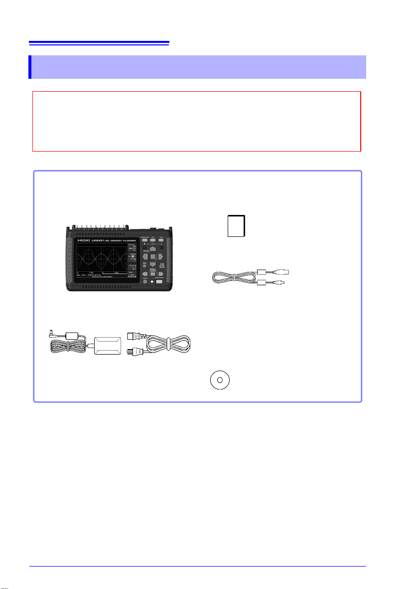
When you receive the instrument, inspect it carefully to ensure that no damage
occurred during shipping. In particular, check the accessories, panel switches,
and connectors. If damage is evident, or if it fails to operate according to the
specifications, contact your dealer or Hioki representative.
Confirm that these contents are provided.
Model LR8431-20 .........................1
Memory HiLogger
Model Z1005 AC Adapter............1
with supplied power cord
(p. 30)
Measurement Guide....................1
USB Cable.................................... 1
CD .................................................1
• Instruction Manual (PDF)
(This document)
• Logger Utility Instruction Manual (PDF)
• Logger Utility (Data acquisition
application program)
(p. A26)
The latest version can be
downloaded from our web site.
Confirming Package Contents
Confirming Package Contents
About options:
Contact your dealer or Hioki representative for details.
Model 9780 Battery Pack
Model Z1005 AC Adapter
Model 9641 Connection Cable (for pulse inputs)
Model 9782 Carrying Case
Model 9812 Soft Case
Model 9727 PC Card (256MB)
Model 9728 PC Card (512MB)
Model 9729 PC Card (1GB)
Model 9830 PC Card (2GB)
Model 9809 Protection Sheet
3
Safety Information
Safety Information
This instrument is designed to comply with IEC 61010 Safety
Standards, and has been thoroughly tested for safety prior to
shipment. However, mishandling during use could result in
injury or death, as well as damage to the instrument.
However, using the instrument in a way not desc
manual may negate the provided safety features.
Be certain that you understand the instructions and precautions in the manual before use.
ity for accidents or injuries not resulting directly from
instrument defects.
This manual contains information and warnings essential for safe operation of the
instrument and for maintaining it in safe operating condition. Before using it, be sure
to carefully read the following safety precautions.
e disclaim any responsibil-
W
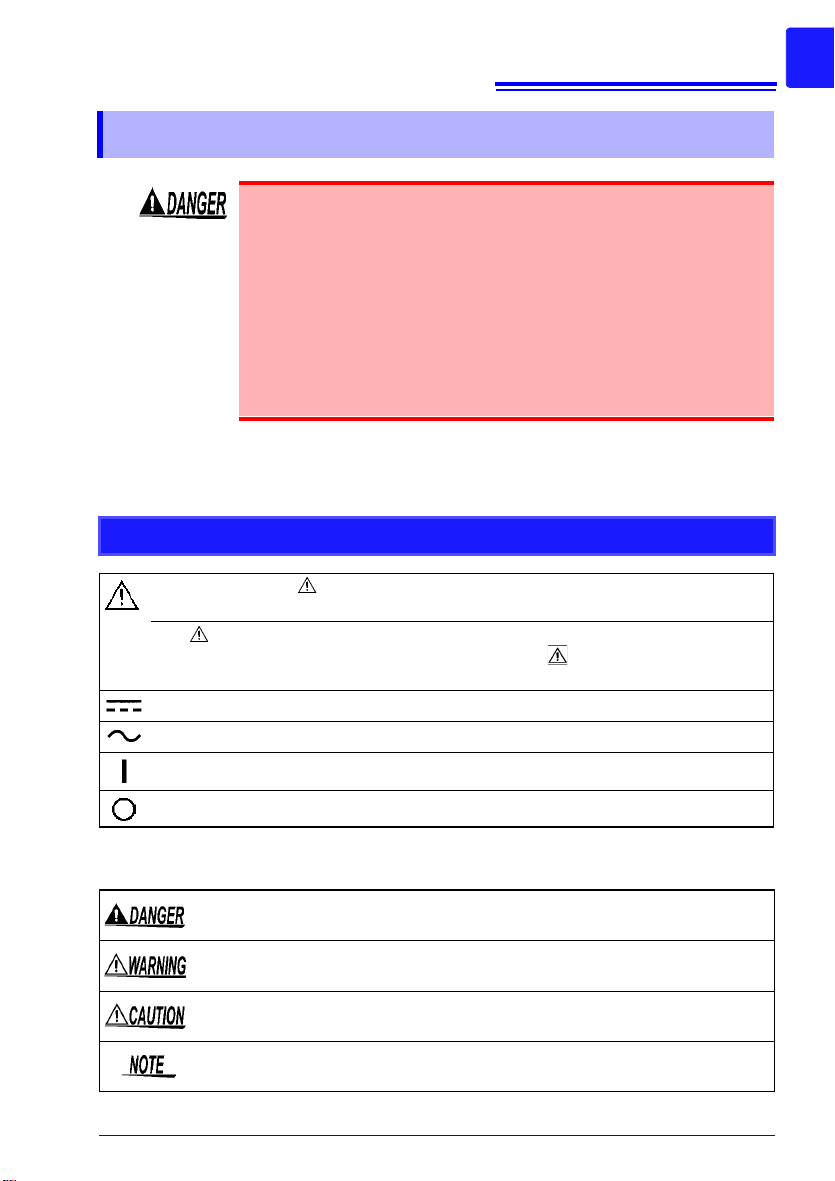
Safety Symbols
In the manual, the symbol indicates particularly important information that the
user should read before using the instrument.
The symbol printed on the instrument indicates that the user should refer to a
corresponding topic in the manual (marked with the symbol) before using the
relevant function.
Indicates DC (Direct Current).
Indicates AC (Alternating Current).
r
ibed in this
Indicates the ON side of the power switch.
Indicates the OFF side of the power switch.
The following symbols in this manual indicate
and warnings.
Indicates that incorrect operation presents an extreme hazard that could
result in serious injury or death to the user.
Indicates that incorrect operation presents a significant hazard that could
result in serious injury or death to the user.
Indicates that incorrect operation presents a possibility of injury to the user
or damage to the instrument.
Indicates advisory items related to performance or correct operation of the
instrument.
the relative importance o
f cautions
4
Ni-MH
Safety Information
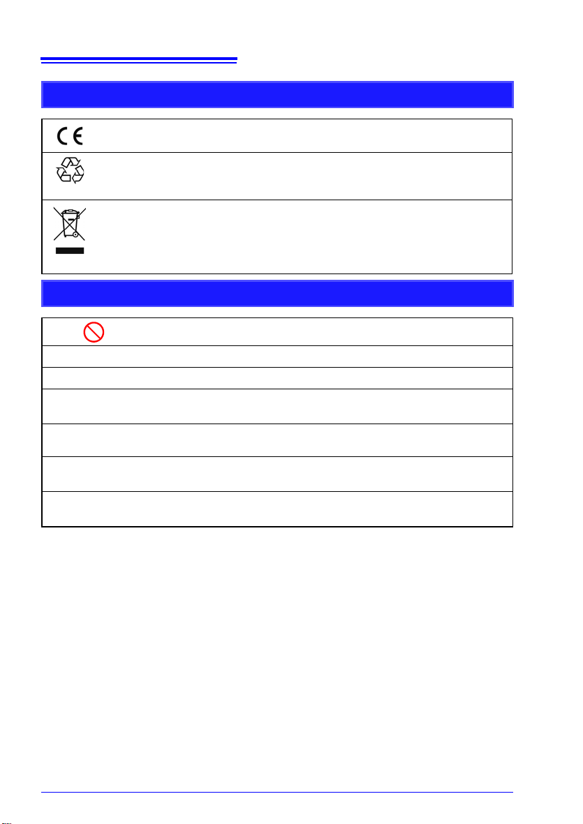
Symbols for Various Standards
This symbol indicates that the product conforms to regulations set out by the
EC Directive.
This is a recycle mark established under the Resource Recycling Promotion
Law
WEEE marking:
This symbol indicates that the electrical and electronic appliance is put on the
EU mark
required to display it on the appliance under Article 11.2 of Directive 2002/96/
EC (WEEE).
Other Symbols
or Japan).
(only f
et after August 13, 2005, and producers of the Member States are
Indicates the prohibited action.
(p. #)
[ ]
SET
(Bold characters)
Unless otherwise specified, "Windows" represents Windows 2000, Windows XP, Windows Vista, Windows 7 or Windows 8.
Click: Press and quickly release the left button of the mouse.
Double click: Quickly click the left button of the mouse twice.
Indicates the location of reference information.
Indicates that descriptive information is provided below.
The names of setting objects and buttons on the screen are indicated
by square brackets [ ].
Bold characters within the text indicate operating key labels.
Accuracy
We define measurement tolerances in terms of f.s. (full scale), rdg. (reading) and
dgt. (digit) values, with the following meanings:
f.s. (maximum display value or scale length)
The maximum displayable value or scale length. This is
rently selected range.
Example: For the 1 V range, f.s. = 1 V
rdg. (reading or displayed value)
The value currently being measured and indicated on the measuring instrument.
dgt. (resolution)
The smallest displayable unit on a digital measuring instru
that causes the digital display to show a "1" as the least-significant digit.
usually the name of the cur-
ment, i.e., the input value
Safety Information
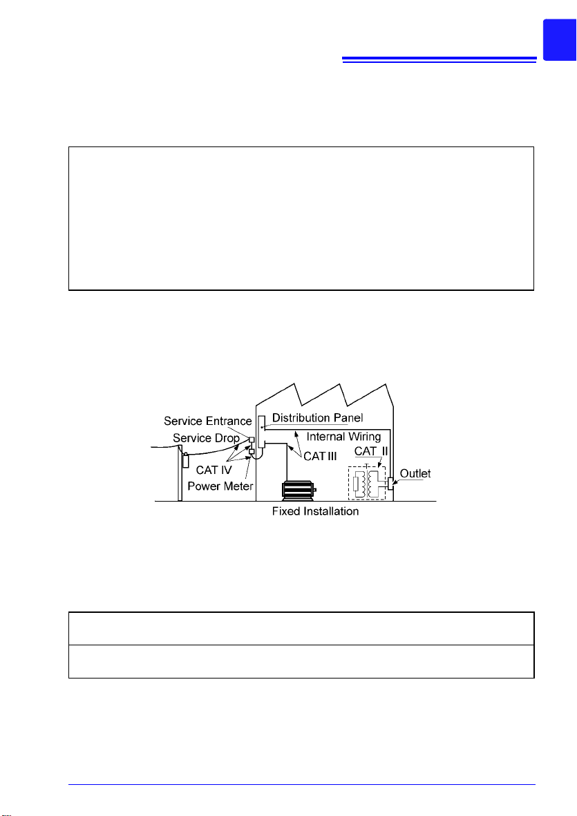
Measurement categories
To ensure safe operation of measurement instruments, IEC 61010 establishes safety standards for various electrical environments, categorized as CAT II to CAT IV, and called measurement categories.
Primary electrical circuits in equipment connected to an AC electrical outlet
CAT II
a power cord (portable tools, household appliances, etc.)
by
CAT II covers directly measuring electrical outlet receptacles.
5
CAT III
CAT IV
Using a measurement instrument in an environment d esignated with a higher-numbered ca tegory than that for which the instrument is rated could result in a severe accident, and must
carefully avoided.
be
Use of a measurement instrument that is not CAT-rated in CAT II to CAT IV measurement
applications could result in a severe accident, and must be carefully avoided.
Primary electrical circuits of heavy equipment (fixed installations) connected
directly to the distribution panel, and feeders from the distribution panel to
outlets.
The circuit from the service drop to the service entrance, and to the power
m
eter and primary overcurrent protection device (distribution panel).
Difference between "Measurement" and "Recording"
The measurement and recording processes are distinguished as follows for the pur poses of
these instructions.
Measurement:
Recording:
Measured data (data acquired in internal memory) is erased whenever a new measurement
starts. To r
The acquisition of input values into internal HiLogger memory or to a PC
via com
Storing measurement data on a CF card, USB flash drive or on a PC via
dat
etain data, always record (save) it.
m
a comm
unications.
unication.
6
Operating Precautions
Operating Precautions
Follow these precautions to ensure safe operation and to obtain the full benefits of
the various functions.
Before Use
• Before using the instrument for the first time
, verify
that it operates normally to
ensure that no damage occurred during storage or ship ping. If you find any damage, contact your dealer or Hioki representative.
• Before using the instrument, make sure that the insulation on the cables is undamaged and that no bare conductors are improperly ex
posed. Using the instrument in
such conditions could cause an electric shock, so contact your dealer or Hioki representative for replacements.
Instrument Installation
• Operating temperature and humidity: 0 to 40°C a
sating)
• Temperature and humidity range for guaranteed accuracy:
less
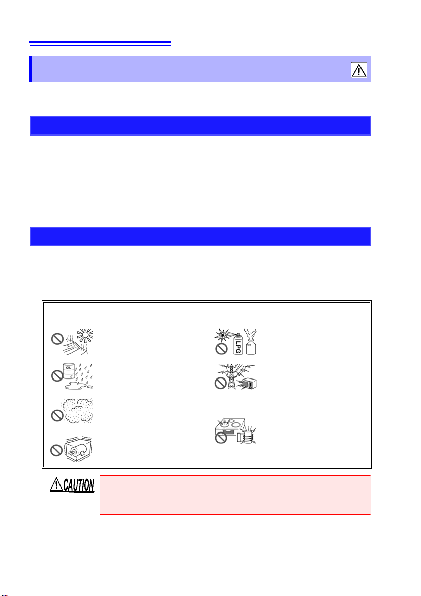
Avoid the following locations that could cause an accident or damage to the
instrument.
Exposed to direct sunlight
Exposed to high temperature
Exposed to water, oil, other
chemical
Exposed to high humidity or
condensation
Exposed to high levels of
particulate dust
Sub
s, or solvents
ject to vibration
t 80% RH or less (non-conden-
23±5°C, 80%RH or
In the presence of corrosive
or explosive gases
osed to strong electro-
Exp
magnetic fields
Near electromagnetic radiators
Near induction heating systems
(e.g., high-frequency induction heating systems and IH
cooking utensils)
The maximum operating (ambient) temperature for the LR8431-20
is 40°C. Do not attempt to use in higher temperature environments.

• Correct measurement may be impossible in the presence of
Horizontal placement Upright placement
strong magnetic fields, such as near transformers and high-cur
rent conductors, or in the presence
fields such as near radio transmitters.
• If liquid enters the enclo sure through an air vent or othe r opening, it
ma
y dam
cerning the surrounding environment when inst alling the instrument .
Installation Precautions
• If the instrument is used in any state other than the following, the
measurement accuracy may not satisfy the device specifications.
• Leave sufficient space around the ventilation holes and install the
instrument
• Avoid temperature changes around the terminal block. Espe
avoid directed airflow such as from an electric fan or air conditioner
vent.Thermocouple inputs are prone to measurement errors.
• When the HiLogger is moved to a location with significantly different ambient temperature, allow at lea
equalization before measuring.
7
Operating Precautions
-
of strong electromagnetic
age the instrument's internal circuitry. Exercise caution con-
with the holes unobstructed.
cially
st 30 minutes for thermal
Handling the Instrument
• Do not allow the instrument to get wet, and do not take measurements with wet hands. This may cause an el ectric shock.
• Do not attempt to modify, disassemble or rep
ment; as fire, electric shock and injury could result.
To avoid damage to the instrumen t, protect it from physical shock
when transporting and handling. Be especially careful to avoid
physical shock from dropping.
This instrument may cause interference if used in residential
areas. Such use must be avoided unless the user takes special
measures to reduce electromagnetic emissions to prevent interfer
ence to the reception of radio and television broadcasts.
air the instru-
-
8
Operating Precautions
Handling the Cords and Cables
• Avoid stepping on or pinching cables, which could damage the
cable insulation.
• To avoid breaking the cables and probes, do n
• To avoid damaging the power cord, grasp the plug, not the cord,
when un
Before Turning Power On
Using the Battery Pack
• For battery operation, use only the HIOKI Model 9780 Battery
Pack. We do not take any responsibility for accidents or
damage related to the use of any other batteries.
See: 2.1, "Using the Battery Pack (Option)" (p. 26)
Using the AC Adapter
• Use only the supplied Model Z1005 AC Adapter. AC adapter
input voltage range is 100 to 240 VAC (with ±10% stability) at
50/60 Hz. To avoid electrical hazards and damage to the
instrument, do not apply voltage outside of this range.
• Turn the instrument off before connecting the AC
the instrument and to AC power.
• To avoid electrical accidents and to maint ain the safety specifications of this instrument, connec
vided only to a 3-contact (two-conductor + ground) outlet.
• Use only the designated power cord
Use of other power cords may cause fire.
• Before turning the instrument on, make sure the s
age matches that indicated on its power
tion to an improper supply voltage may damage the
instrument and present an electrical hazard.
plugging it from the power outlet.
ot bend or pull them.
dapter to
a
t the
power cord pro-
with this instrument.
upply volt-
connector. Connec-
When the power is turned off, do not apply voltage or current to
the connectors. Doing so may damage the instrument.
• After use, always turn OFF the power.
• Brief power interruptions of 40 ms or less will not cause this
instrument to malfunction. However, Longer interruptions may
cause the Memory HiLogger to shut itself off, so consider local
power conditions before installing, as appropriate.
• To ensure that recording is not interrupted by power outages, you
can use the Z1005 AC
Adapter and 9780 Battery Pack together.

About Inputs and Measurement
• The maximum input voltage (and the maximum rated voltage to earth) for the analog input terminals is
V DC). If these limits are exceeded, the instrument may be
damaged and personal injury or death could occur, so do
not attempt measurement.
• Do not leave the Memory HiLogger connected to test objects
in
environments where a voltage surge might exceed the
dielectric withstand voltage. Doing so could result in damage
to the Memory HiLogger, bodily injury or fat al accident.
• Channels are insulated by semiconductor
voltage beyond the specification is applied between the
channels, the semiconductor relay may short circuit. Please
ensure that a voltage beyond specification, especially a
surge such as a lightning, is never applied. When an abnormal measurement value is observed, please contact your
dealer or Hioki representative for inspection.
The waveform for an open channel may sometimes appear to be
influenced by the signals of the other channels being measured. If
you do not like this, please set the waveform display of the open
channel to OFF or short-circuit the input terminals of the open
channel by connecting the positive and negative terminal.
9
Operating Precautions
30 Vrms (or 60
relays. When a

10
Operating Precautions
CD Handling
• Always hold the disc by the edges, so as not to make fingerprints
on the disc or scratch the printing.
• Never touch the recorde d side of the disc. Do not place the disc
dire
• Do not wet the disc with volatile alcohol or water, as there is a
possibility of th
• To write on the disc label surface, use a spirit-based felt pen. Do
not
use a ba
danger of scratching the surface and corrupting the data. Do not
use adhesive labels.
• Do not expose the disc directly to the sun's rays, or keep it in
conditions of high temp
of warping, with consequent loss of data.
• To remove dirt, dust, or fingerprints from the disc, wipe with a dry
clo
t
outside, and do no wipe with circular movements. Never use
abrasives or solvent cleaners.
• Hioki shall not be held liable for any problems with a computer
syste
related to the purchase of a Hioki product.
ctly on a
h, or use a CD cleaner. Always wipe from the inside to the
nything hard.
e label prin
ll-point pen or hard-tipped pen, because there is a
t arises from the use of this CD, or for any proble m
m tha
ting disappearing.
ture or humidity, as there is a danger
era
Using a CF Card/USB flash drive
USB method of use
Connector
used
[System] screen USB
mode setting
Use a USB flash drive. Type A USB Memory (Default)
Communicate with the LR8431-20
and initiate measurement using the
Logger Utility software from a computer (using a USB cable).
Type B USB Communication
Read files on a CF card that is connected to the LR8431-20 from a
computer (using a USB cable).
Type B USB Drive
• Inserting a CF card/USB flash drive upside down, backwards or in the
wrong direction may damage the CF card, USB flash drive, or HiLogger.
• Never eject a CF card /USB flash drive while measuring or when the
HiLogger
drive may be destroyed. (The CF icon/USB flash drive icon at the
lower right is red while the card is being accessed.)
• Do not transport the HiLogger while a USB flash drive is connected.
Dam
• As th e CF card/ USB flash dr ive is sensi tive t o static electr icity, damage
to the CF card/USB flash driv e or wrong operations by the HiLogger
may occur due to static electricity. Please be careful when handling it.
• With some USB flash drives, the HiLogger may not start up if power is
turned
power on first, and then insert the USB flash drive. It is recommended
to try out operation with a USB flash drive before starting to use it for
actual measurements.
• The Flash memory in a CF card/USB flash drive has a limited operating life. After long-term usage, data storage and retrieval become difficult. In this case, replace the CF card/USB flash drive with a new one.
• We cannot provide compensation for data loss in a CF card/USB flash
dr
from memory if a long time passes after measuring. Always maintain a
backup of important data stored on a CF card/USB flash drive.
• Although real-time saving to USB flash drive is supported, a CF card is
r
ec
when using storage media othe r than a Hiok i-s pecifie d CF ca rd o ption.
• Use a USB flash drive whose continuous current consumption does not
exce
Power" under the USB flash drive self- test o n the [Syste m] sc re en.)
• Depending on how USB is used, the USB connector and instrument settings may vary as shown in the cha rt belo w.
• The three USB methods of use described in the chart below involve
exclu
is or accessing the card. Data on the CF card/USB flash
age could result.
on while the USB flash drive is inserted. In such a case, turn
ive, regardless of content or cause of the damage. Data is also clear ed
ommended for data preservatio n. Performance ca nnot be guaranteed
ed 300 mA (peak 500 mA). (The peak value is displayed as "Max
sive settings and cannot be us ed sim ult an eousl y.
11
Operating Precautions

12
Operating Precautions
13
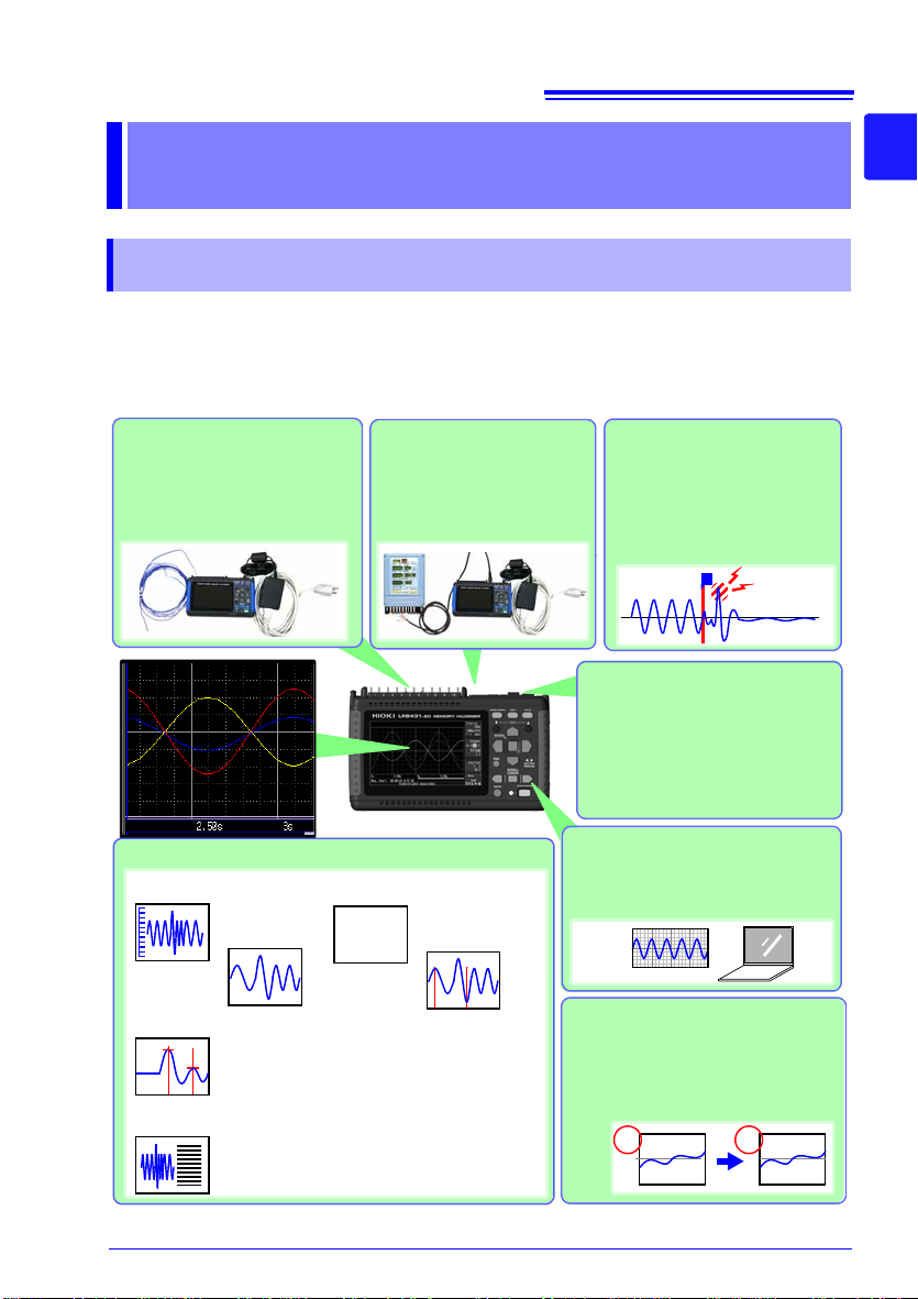
Record anomalies
Abnormal events can be analyzed by recording with the
trigger function (p. 67)
Use the alarm function to output signals when anomalies
occur (p. 73).
Measurement data and
setting configurations are
stored, read and managed
as data files
Measurement data can be stored
to and read from a CF card or
USB flash drive (p. 91).
Waveform analysis
mV A
Cursor Measurements (p. 84)
A
B
Using the A/B cursors, values at cursor locations on waveforms and the time at trigger positions can be displayed.
Performs six calculation types, including
maximum and average values.
Numerical Calculations (p. 113)
123.4V
Acquire pulse signals
Measure integrated pulses
or revolutions from sensors
and pulse output devices
such as watt-hour meters.
Gauge display (p. 84)
Zoom in/out
(p. 83)
Numerical display (p. 87)
Analysis on a PC
Monitor and analyze measurement
data with the supplied application
program (p. A19).
Event search
(p. 88)
T
1 2
Display in converted units
Using the scaling function, input values can be displayed in units of the
actual physical quantity being measured, such as current or flow volume (p. 58).
Observe voltage fluctuations and temperature
changes
Just connect measurement
leads or thermocouples to measure as needed.
1.1 Product Overview and Features
Overview Chapter 1
1.1 Product Overview and Features
The Hioki LR8431-20 Memory HiLogger is a compact, lightweight, easy-tooperate waveform recorder. It can run on batteries, and can be quickly
deployed when a power anomaly occurs.
Measurement data can be monitored, subjec
on a personal computer using the supplied application program.
d to calculations and analyzed
te
1
Chapter 1 Overview
3
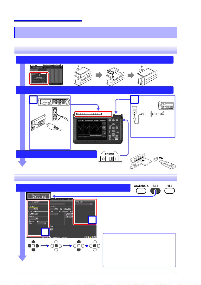
14
To save data, insert a
CF card or USB flash
drive. (p. 94)
AC adapter
connection (p. 30)
Install the Battery Pack (option) (p. 26)
Connect to the Model LR8431-20 (p. 25), and Set Up (p. 7)
Turn the Power On (p. 34)
Measurement
cables connections
(p. 31)
1
2
Configure Recording Settings (p. 38)
Using a previously saved
setting configuration
Reload a previously stored setting configuration from Model LR8431-20
memory or a CF card or USB flash
drive, and measure (p. 103)
Set the data acquisition (recording) interval, and recording length (time span).
Select the type of measurement data to
save when automatically saving to a CF
card or USB flash drive.
Remaining data stored in the instrument
can be saved when finished measuring.
Move to a
setting item
Open the
setting options
Select Apply
1
2
1.2 Measurement Flow
1.2 Measurement Flow
Installing, Connecting and Turning On
Settings
1.2 Measurement Flow
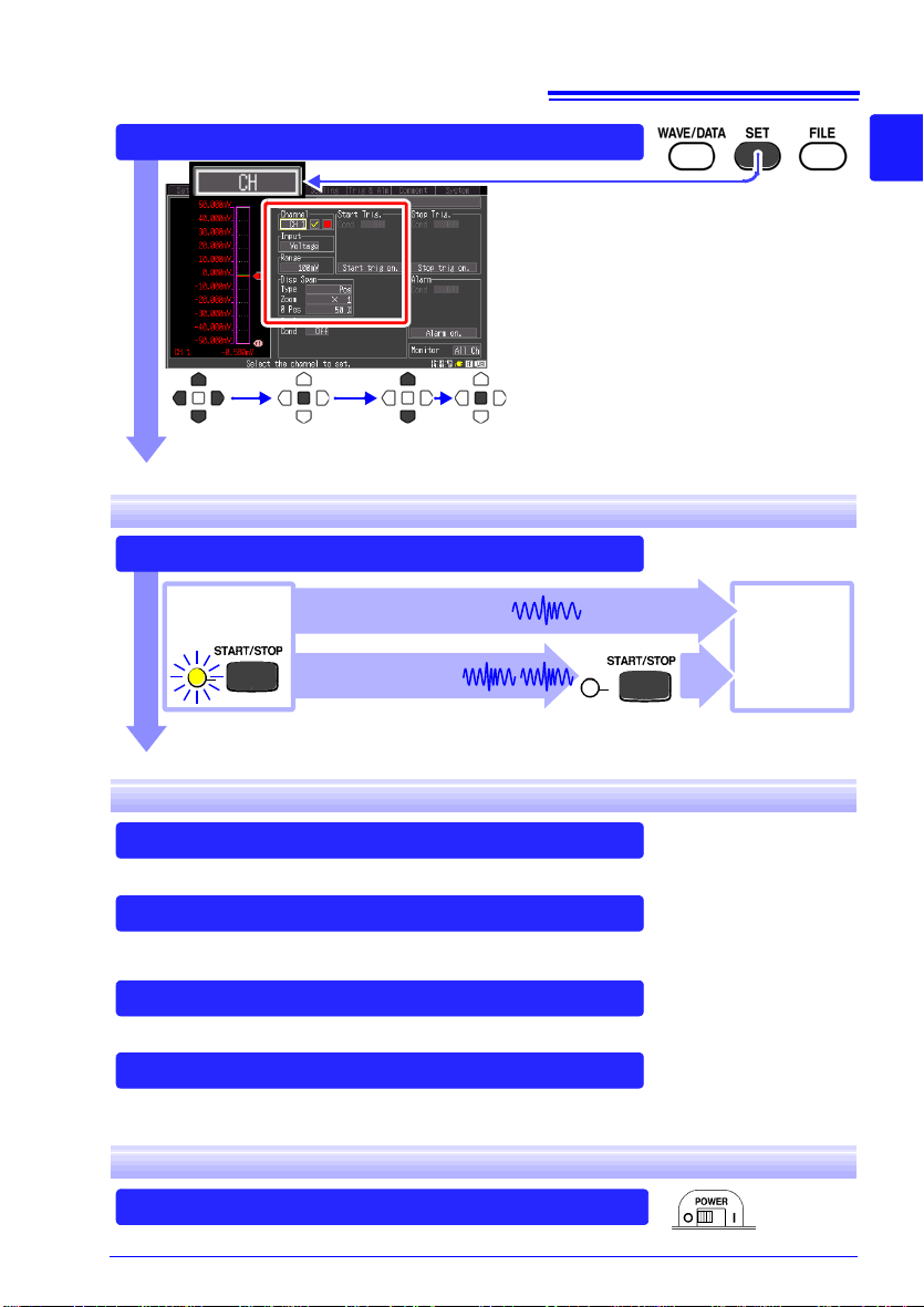
Configure Input Channels (p. 38)
Select input channels, and set input types
and measurement ranges.
Make other settings as desired.
Move to a
setting item
Open the
setting options
Select Apply
Press the START/STOP Key (p. 22)
Record once, and stop.
[Repeat]: Off
Stop
Measurement
Start
Measurement
When recording using the trigger function, recording occurs only
when the input waveform satisfies specified trigger criteria.
Record repeatedly.
[Repeat]: On
(default setting)
View Measurement Data (p. 81)
Waveforms can be zoomed and numerical values confirmed.
Save Data (p. 91)
Measurement data, waveform data, screen images and numerical calculation
results can be saved.
Calculate (p. 1 1 3)
Numerical measurement data can be applied to calculations.
View on a Computer (p. A19)
Analyze recorded data using the supplied application program.
Turn the Memory HiLogger Off (p. 34)
Starting and Stopping Measurement
15
1
Chapter 1 Overview
3
Data Analysis
When Finished
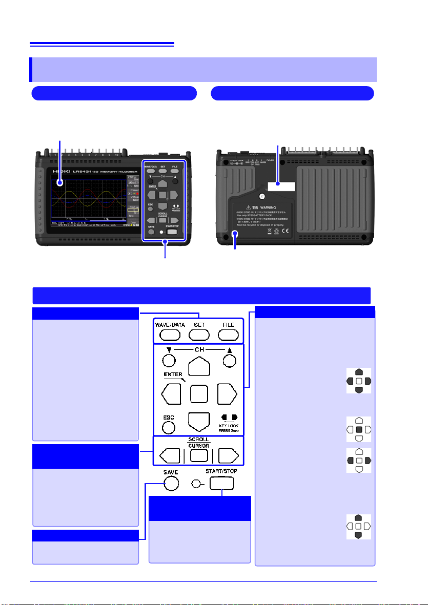
16
Front Panel
Operating Keys
Rear Panel
Battery Compartment (p. 26)
The optional Model 9780 Battery Pack is
installed here.
Manufacturer's Serial No.
Shows the serial number.
Do not remove this label, as it is required
for product support.
Display Screen (p. 81)
4.3-inch TFT color LCD
Screen Configurations (p. 18)
WAVE/DATA
Selects among waveform
screen displays (p. 18).
SET
Displays the Settings
screens, and switches
among the screen tabs
with each press (p. 20).
FILE
Displays file information
(p. 19).
CH/
Select channels.
ESC
Cancels changes to settings.
Cursor Keys
Moves the position of
the cursor (blinking
selection) on the
screen.
ENTER
Accepts displayed
settings.
KEY LOCK
Disables keypad operations. Press and
hold the left and right
cursor keys simultaneously for
three seconds to lock and unlock the keys.
(Zero Adjust)
Performs zero adjustment. Press the up
and down keys simultaneously to execute (p. 35).
Press to save data manually (p. 96).
Press the center key to
select waveform scrolling
or A/B cursor movement,
then press the left and
right cursor keys to scroll
or move (p. 21).
Setup and display
Saving operations
Scroll waveforms and
read cursor values
Choose a screen
Start and stop measurement. The LED at the left
lights green while measuring (p. 22).
Start and stop
measurement
Operating Keys
1.3 Names and Functions of Parts
1.3 Names and Functions of Parts
17
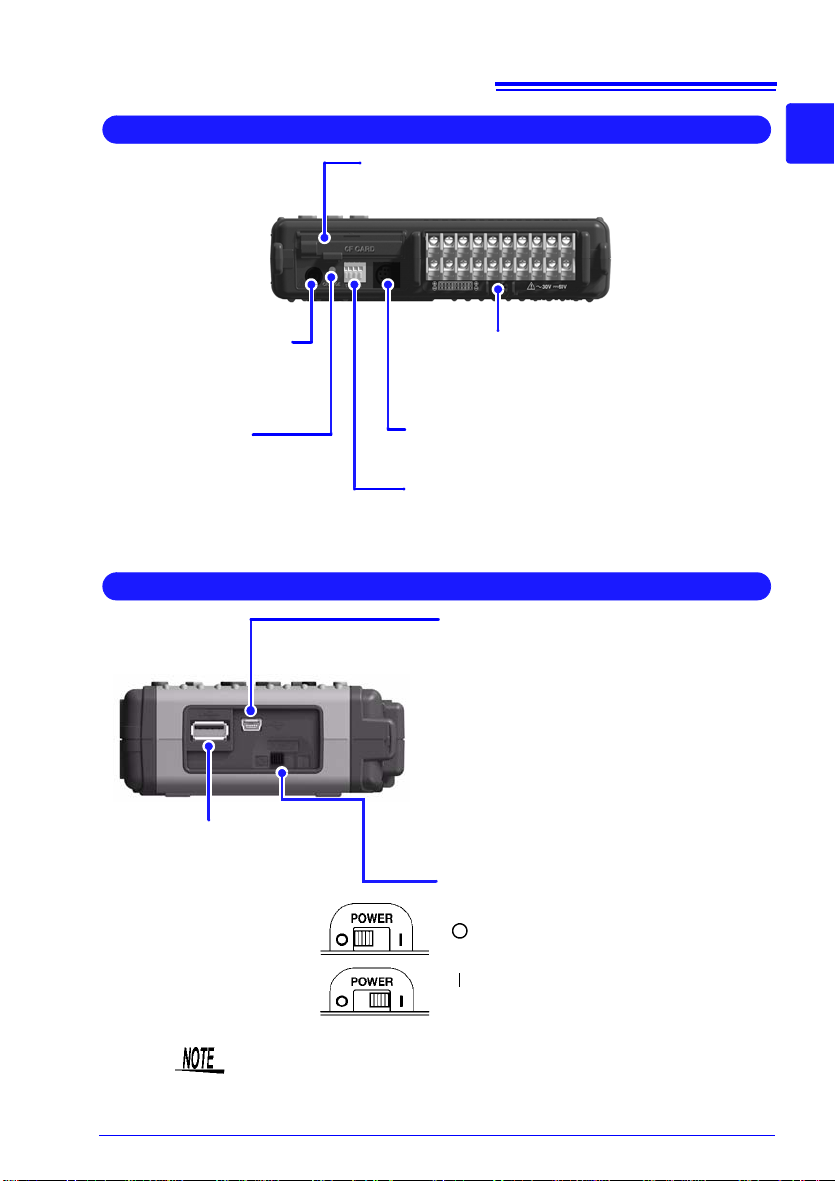
Top Panel
AC Adapter Socket
Connect the supplied Model
Z1005 AC Adapter (p. 30).
CF Card Slot
Insert an optional CF card. (p. 93)
Analog Input Terminals
Connect measurement leads for voltage measurement, and thermocouples for temperature
(p. 31).
CHARGE LED
This LED lights when the
battery is charging (p. 29).
Pulse Input Connector
Connect an optional 9641 cable (p. 33).
External Control Terminals
Control signals can be received from and
output to external devices (p. 129).
Right Side
POWER Switch
Turns the instrument on and off (p. 34)
Power Off
Power On
USB Port
(USB 2.0 mini-B receptacle)
• Using the included Logger Utility application software, you can monitor measurement data on the computer and transfer
settings to the instrument. (p. A26) (To
use, set the USB mode on the [System]
screen to [USB Communication].)
• You can transfer data on the instrument’s
CF card to a computer. (p. 110) (To use,
set the USB mode on the [System]
screen to [USB Drive].)
USB flash drive Slot
(Type A USB 2.0
receptacle)
Used to save data to a
USB flash drive. (p. 94)
(To use, set the USB
mode on the [System]
screen to [USB Memory].)
1.3 Names and Functions of Parts
1
Chapter 1 Overview
3
The [USB Memory], [USB Communication], and [USB Drive] USB
mode settings are exclusive and cannot be used simultaneously.
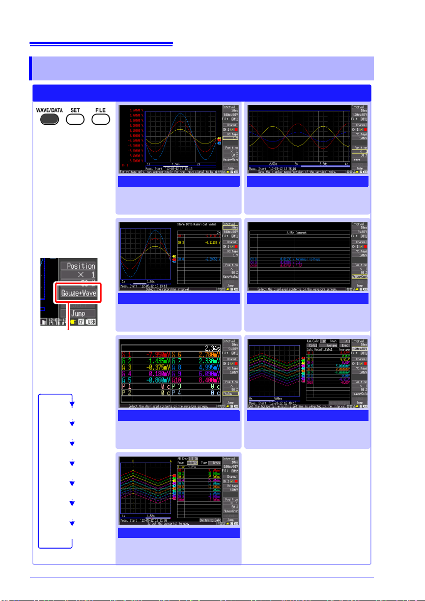
18
Selects between
seven display
types.
The screen switches
each time you press
the key.
Operational information is displayed
along the bottom of
the screen.
[Wave] Screen
Measurement data is displayed
as waveforms (p. 81).
[Value+Cmnt] Screen
Measurement data is displayed
as numerical val ues with comments (p. 87).
[Wave+Calc] Screen
Measurement data is displayed
as waveforms with calculation
results (p. 115).
[Gauge+Wave] Screen
Measurement data is displayed
as waveforms with gauges (p.
84).
[Wave+Value] Screen
Measurement data is displayed
as waveforms and numerical
values (p. 87).
[Value] Screen
Measurement data is displayed
as numerical values (p. 87).
[Wave+Crsr] Screen
Measurement data is displayed
as waveforms with cursor values (p. 84).
Waveform/Numerical Screens
Selection is also
available from the
name of the current
screen displayed
near the bottom right
[Gauge+Wave]
[Wave]
[Wave+Value]
[Value+Cmnt]
[Value]
[Wave+Calc]
[Wave+Crsr]
1.4 Screen Configurations
1.4 Screen Configurations
19
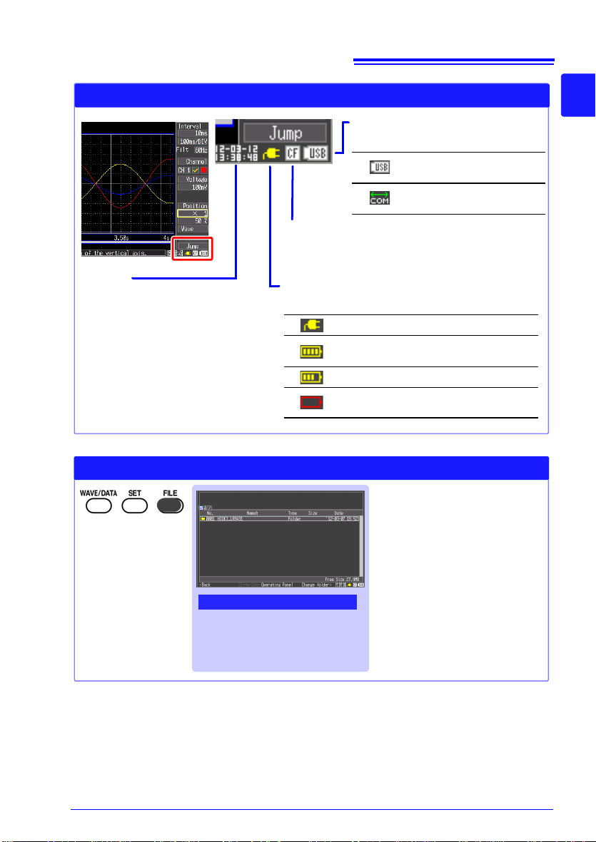
Waveform/Numerical Screens (About the Icons)
Clock
"Setting the Date and Time"
(p. 124)
Power source indicator
Indicates the Memory HiLogger's power source.
AC adapter operation
Battery pack operation
(
Fully charged battery pack)
Battery pack operation
Battery pack operation
(Low battery indicator)
CF card
Displayed when a CF card is inserted.
The icon appears red when accessing the card.
USB source indicator
Indicates the USB status.
Operating in USB
Memory mode.
Operating in USB
Communication mode.
File Screen
View and manage files on the
CF card or USB flash drive
(p. 91).
File Screen
Operational information is displayed
along the bottom of
the screen.
1.4 Screen Configurations
1
Chapter 1 Overview
3

20
[CH] Screen
Make input channel settings
while viewing the monitor display (p. 49).
[Scaling] Screen
Make these settings to convert
measured values to arbitrary
units for display (p. 58).
[Comment] Screen
Enter channel comments
(p. 60)
[Setting] Screen
[Range] Screen
Make settings while viewing all
channel settings (p. 62).
[Trig & Alm] Screen
Recording criteria (triggering)
and warning sounds can be set
for each channel (p. 67).
[System] Screen
Configure the system environment (p. 119).
Settings Screens
Press the left/right
cursor keys to select between the
Settings screens.
Selects between
seven display
types.
The screen switches each time you
press the key.
Operational information is displayed
along the bottom of
the screen.
Make settings for recording (p.
42). Set numerical calculation,
auto-saving and timers.
1.4 Screen Configurations
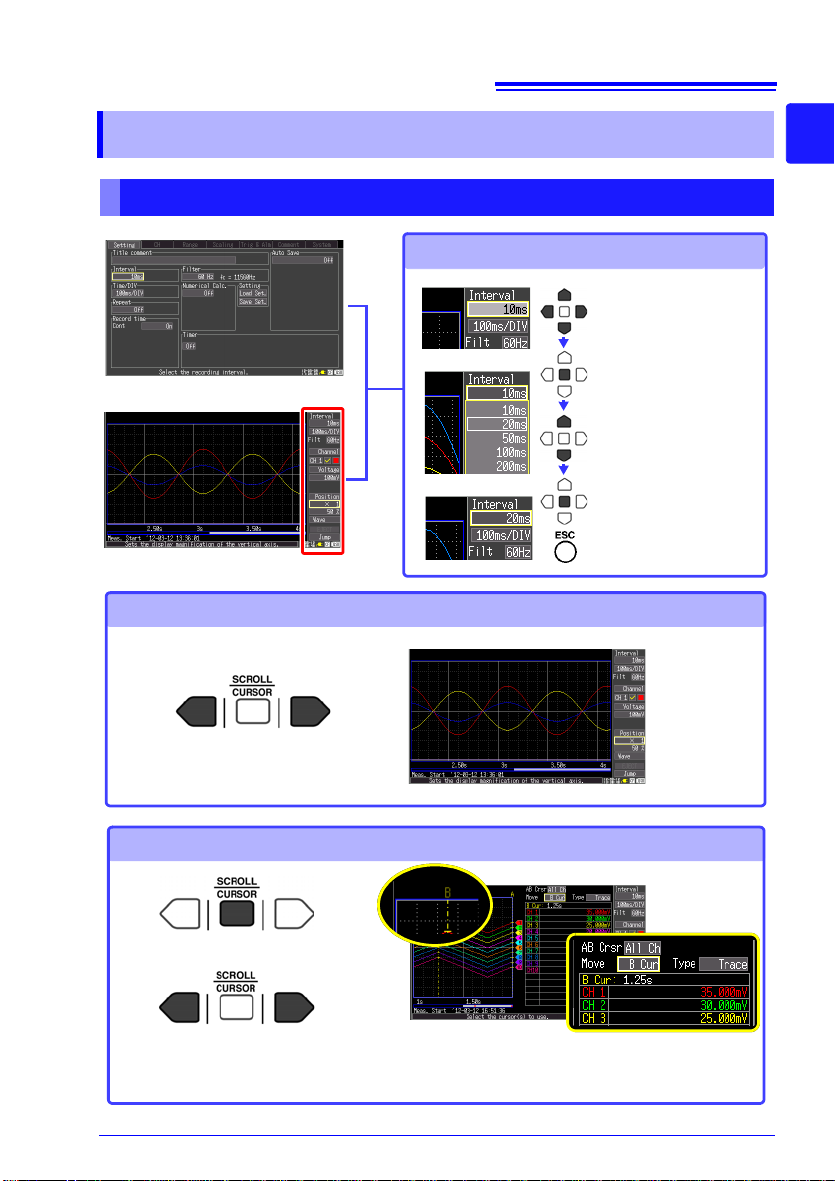
21
Select the item to
change.
Show available
setting options.
Select the desired
setting.
Changing screen contents
Setting Screen
Waveform Screen
Apply the new
setting,
or cancel it.
Scrolling a waveform
Earlier
Later
See: "Scrolling Waveforms" (p. 82)
Reading values at cursors
1
Display the A/B cursors.
2
Move the A/B cursors.
Values at cursor positions can be
read numerically.
You can select the cursor
display type and which cursor(s) to move (p. 84).
1.5 Basic Operation
1.5 Basic Operation
Screen Operations
1
Chapter 1 Overview
3
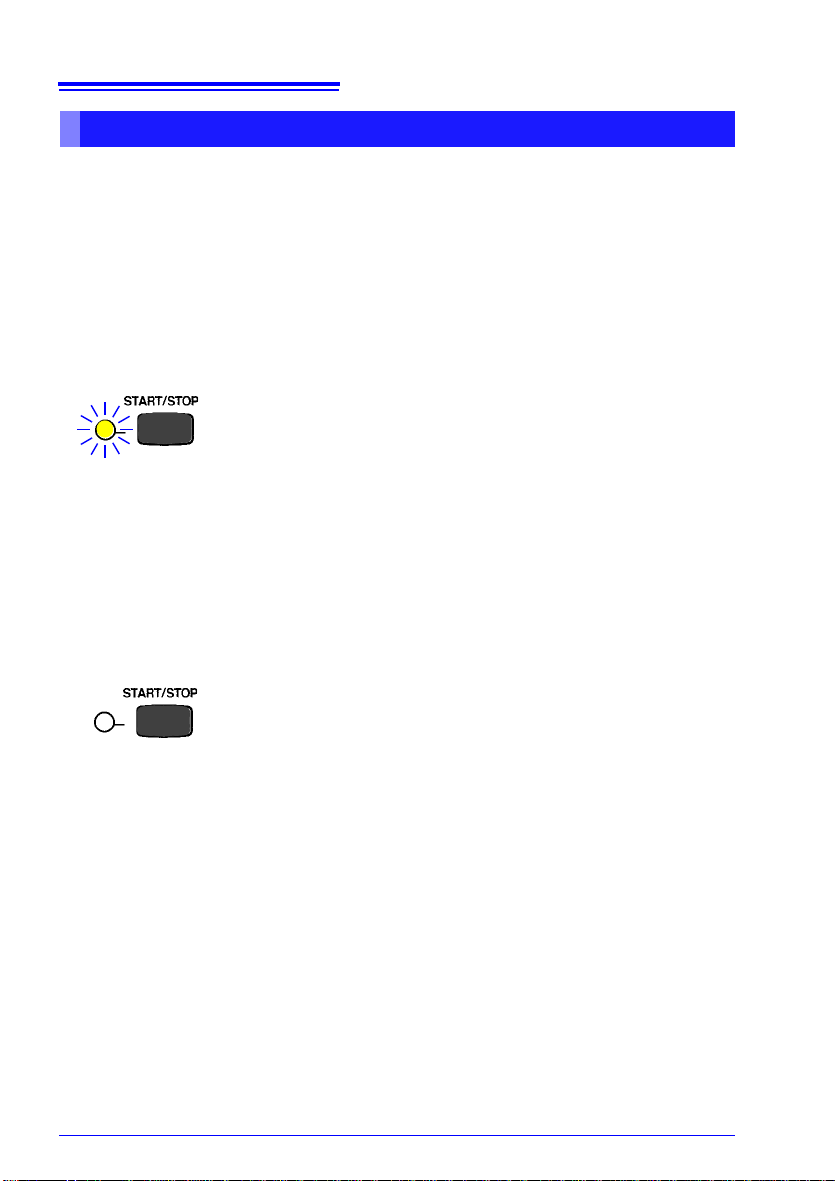
22
Press the START/STOP key.
The green LED lights.
When using the trigger function, the times when measurement
starts and when recording (data acquisition) starts are not the
same.
A confirmation message appears when you press the
START/
STOP
key to start recording. Save important data to a CF card
or USB flash drive before starting, because previous measurement data will be overwritten when recording starts.
Start Measurement
When [Repeat] (record multiple instances of the specified
recording length) or
[Cont] (record continuously) is
enabled:
Pressing the
START/STOP key stops recording.
When
[Repeat] and [Cont] are disabled (Off):
Recording stops after the specified recording length. Pressing
the
START/STOP key during recording displays a confirmation
message. Select
[Yes] to stop recording.
For details about repeating and continuous recording:
See: "Selecting the Recording Start/stop Method" (p. 44)
"Set the Recording Length for Repeated or One-time Recording" (p. 45)
Finish Measurement
1.5 Basic Operation
Starting and Stopping Recording
Acquire measurement data on the Memory HiLogger, and start recording.
When recording stops depends on data recording settings (repeat recording,
tr
iggering, timers, etc.). (p. 78)
When you want measurement data to be automatically saved, before starting
recording, check that auto
is correctly inserted (p. 94), and that sufficient storage capacity is available (p. A11).
-save is enabled (p. 46), that a CF card or USB flash drive
 Loading...