

Hioki LR8410-20 Instruction Manual


Contents
Introduction ..............................................................................1
Confirming Package Contents................................................2
Safety Information....................................................................4
Operating Precautions.............................................................7
Chapter 1
Overview ____________________________________21
1.1 Product Overview and Features .............................21
1.2 Measurement Flow ..................................................22
1.3 Names and Functions of Parts, Screen
Configurations .........................................................26
Wireless Logging Station ................................................. 26
UNIT ................................................................................. 29
Measurement Units ..........................................................30
Wireless logger ................................................................31
Types of wireless logger .................................................. 31
LR8512 Wireless Pulse Logger ........................................ 31
LR8513 Wireless Clamp Logger ......................................31
LR8514 Wireless Humidity Logger ................................... 32
LR8515 Wireless Voltage/Temp Logger ..........................32
LR8520 Wireless Fungal Logger ......................................32
1.4 Basic Operation .......................................................35
Screen Operations
(changing settings, scrolling waveforms,
and displaying values).......................................................35
Starting and Stopping Measurement ................................36
Disabling Key Operations (Key-Lock Function) ...............38
Performing Zero Adjustment ............................................ 38
Saving Data ......................................................................39
Confirming Inputs (Monitor) .............................................. 40
i
Contents
1
2
Chapter 2
Measurement Preparations _________________41
2.1 Using the Battery Pack (Option) ............................41
Install the Battery Pack ....................................................41
Charge the Battery Pack .................................................. 42
LR8410B980-05

ii
Contents
2.2 Connecting the AC Adapter ................................... 44
2.3 Making Connections ............................................... 46
Pre-Connection Inspection ............................................... 46
Voltage and Thermocouple Temperature Measurement .47
Temperature Measurement with
a Resistance Temperature Detector (RTD) .....................49
Humidity Measurement .................................................... 50
Resistance Measurement ................................................ 51
Connecting Alarm Outputs ............................................... 52
External Control (using TRIG OUT and EXT TRIG) ........ 53
2.4 Turning the Power On and Off ............................... 54
2.5 Register measurement units and
wireless logger with the instrument ...................... 55
Registering Measurement Units and Wireless Logger ..... 56
Deleting Registered Units ................................................58
2.6 Inserting a SD Memory Card or USB Flash Drive
(when saving data) ................................................. 60
SD Card Insertion & Removal .......................................... 61
USB flash drive Insertion & Removal ............................... 61
Formatting a SD memory card/USB flash drive ............... 62
2.7 Compensating for Input Circuit Offset
(Zero Adjustment) .................................................... 63
Chapter 3
Settings _____________________________________ 67
3.1 Setting Flow Overview ........................................... 67
3.2 Configuring Measurement Settings ...................... 68
Time Setting by Key Operations ......................................68
3.3 Input Channel Settings ........................................... 72
Key Setting Procedure ..................................................... 73
Voltage Measurement Settings ........................................ 75
Temperature Measurement Settings
(using thermocouples) ...................................................... 76
Temperature Measurement Settings (for RTDs) ............. 78
Temperature Measurement Settings
(When LR8514 or LR8520 is used) .................................. 79
Humidity Measurement Settings (When LR8511 is used) 80
Humidity Measurement Settings
(When LR8514 or LR8520 is used) .................................. 80

Resistance Measurement Settings ..................................81
Integration (Count) Measurement Settings ......................82
Revolution Measurement Settings ...................................84
Logic Measurement Settings ............................................86
Current Measurement Settings ........................................87
Fungal Index and Fungal Growth Projection Settings ...... 89
3.4 Alarm Settings .........................................................90
3.5 Data Saving Settings ...............................................90
3.6 Waveform Display Settings (as needed) ...............91
Key Setting Procedure .....................................................91
Selecting Waveform Display Color ................................... 91
Specifying Vertical Display Range by Magnification and
Zero Position (vertical axis expansion/compression) .......92
Specifying the Vertical Display Range by Upper and
Lower Limits (expansion/compression) ............................ 93
Setting the Display Time Base
(horizontal axis magnification) ..........................................94
3.7 Scaling Settings (as needed) ..................................95
3.8 Entering Titles and Comments (as needed) ..........98
3.9 Suppressing Noise (Enable Digital Filtering) ......100
3.10 Viewing and Editing with
the All-Channel Settings List ................................101
Batch Copying Channel Settings ...................................102
Batch Setting Waveform Display/Hide and
Waveform Color Settings for All Channels ..................... 104
Initializing Settings (to factory defaults) .......................... 105
Aligning Zero Positions on the Grid ................................106
Setting CH1 of UNIT1 Value as a Scaling Value
(Inter-Channel Compensation function) .........................107
iii
Contents
2
3
4
Chapter 4
Observing Measurements and Data ______ 111
4.1 Confirming Measured Values,
and Starting Measurement ....................................111
If the power goes out during measurement ....................111
If communications fail temporarily .................................. 111
Handling of waveform display and data when
data cannot be acquired..................................................112
Synchronization and acquired data discrepancies ......... 112

iv
Contents
4.2 Observing Waveforms .......................................... 113
Displaying Waveforms (Display Descriptions) ...............113
Displaying Gauges ......................................................... 114
Viewing Input Signals as Numerical Values ................... 115
Scrolling Waveforms ...................................................... 116
Verifying Waveform Display Position ............................. 116
Magnifying and Compressing Horizontally ..................... 117
Viewing Any Waveform Location (Jump Function) ........117
Specifying a Waveform Time Span ................................ 118
Displaying Cursor Values ............................................... 119
4.3 Marking Waveforms and Searching Marks
(Search Function) .................................................. 121
Inserting Event Marks While Viewing Waveforms ......... 121
Inserting Event Marks Using External Input Signals ......122
Alarm Event Marks ......................................................... 123
How are event marks handled in
text (CSV) conversion? ................................................... 124
Searching Event Marks .................................................. 125
Chapter 5
Specifying Criteria for Measurements ____ 127
About Triggering ............................................................ 127
5.1 Triggering Measurement Start and Stop ............ 129
Types of Trigger Criteria ................................................129
Enable the Trigger Function ........................................... 130
Key Setting Procedure ................................................... 130
Setting Trigger Criteria ................................................... 131
Selecting Triggering Criteria (Trigger Source) ...............135
Using External Triggering .............................................. 136
When You Want to Measure Data before Triggering
(Pre-trigger)..................................................................... 137
Applying Trigger at Fixed Time Interval
(Interval Trigger) ............................................................. 138
5.2 Trigger Setting Examples .................................... 139
5.3 Confirming All Trigger and
Alarm Criteria Settings.......................................... 140
5.4 Starting & Stopping Measurement on
a Specified Day ...................................................... 141

5.5 Starting & Stopping Measurement
Periodically .............................................................143
5.6 Canceling a Schedule ...........................................145
5.7 About Schedule Function Operation ...................147
5.8 Setting Examples ...................................................150
5.9 Alarm Output ..........................................................151
Checking Alarm Criteria .................................................152
Alarm Settings ................................................................ 155
v
Contents
Chapter 6
Saving & Loading Data ___________________ 159
6.1 About Saving and Loading Data ..........................159
What happens to data in a power outage? .................... 161
Preparation for power outages during
long-term measurements ................................................161
6.2 Saving Data ............................................................162
Automatic Saving
(Waveform Data and Numerical Calculation Results) .... 163
Replacing Removable Storage During
Real-Time Saving ...........................................................166
Saving Manually (Waveform Data, Settings,
Screen Images, Numerical Calculation Results)............. 167
To Save a Setting Configuration ....................................170
6.3 Loading Data on the instrument ..........................171
Loading a Setting Configuration ..................................... 171
Reverting to previous settings ........................................173
Loading Waveform Data and Screen Images ................174
6.4 Data Management ..................................................176
Switching removable storage .........................................176
Viewing Folder Contents and the Parent Folder ............176
Deleting Data ................................................................. 177
Renaming Files and Folders .......................................... 178
Copying Data ................................................................. 179
Sorting Files ................................................................... 180
6.5 Transferring Data to a PC (USB Drive Mode) ......181
Select the USB Drive Mode ...........................................181
Connecting the USB Cable ............................................182
4
5
6
8

vi
Contents
Chapter 7
Numerical Calculations/
Waveform Calculations____________________ 183
7.1 Calculate Average, Maximum, Minimum,
and Etc.................................................................... 183
Key Setting Procedure ................................................... 186
Real-Time Calculation While Measuring
(Auto Calculation) ........................................................... 186
Calculation after Measuring (Manual Calculation) .........188
Apply Calculations to a Specific Time Span
(Manual Calculation Only) 189
7.2 Numerical Value Calculation Expressions ......... 190
7.3 Waveform Calculations ........................................ 191
Key Setting Procedure ................................................... 191
Calculating Power (When Using the LR8513) ............... 193
Chapter 8
System Environment Settings_____________ 195
Key Setting Procedure ................................................... 196
8.1 Operation Settings ................................................ 196
Using the Auto-Resume Function
(Resume After Power Restoration) ................................ 196
File Protection Level Setting ..........................................197
8.2 Screen Key Operation Settings ........................... 197
Enabling and Disabling the Backlight Saver .................. 197
Adjust Backlight Brightness ........................................... 198
Selecting Black or White Screen Background ............... 198
Enabling or Disabling the Beeper .................................. 198
Selecting the Horizontal (Time) Axis Display .................199
Selecting the Display Language .................................... 199
Display of Start/Stop Confirmation Messages ............... 199
8.3 CSV File Saving Settings ..................................... 200
CSV File Data Decimal and Separator Characters ........ 200
Select the sort order for numerical calculation results ...200
Setting How to Handle Date Data Stored in CSV Files .. 201
8.4 External Trigger Input Settings ........................... 201
Selecting the External Trigger Function ......................... 201
Set Alarm Event Marking ............................................... 201

8.5 Making System Settings .......................................202
Setting the Date and Time .............................................202
Initializing the instrument (System Reset) ...................... 203
Self-Test ......................................................................... 204
Chapter 9
External Control __________________________ 205
9.1 External Trigger Input ...........................................205
9.2 External Signal Output (Trigger Output) .............206
9.3 Alarm Signal Output (Alarm Output) ...................207
9.4 Synchronous Measurements with
Multiple instruments ..............................................209
Chapter 10
Connection to a PC (Communication) ____ 211
Communication Features ............................................... 211
10.1 USB Settings and Connections ............................212
1.Configuring the instrument ..........................................212
2. Installing the USB Driver ............................................ 213
3. Connecting the instrument to a PC ............................216
Features Available After USB Setting and Connection ..218
4. Installing the Logger Utility Program ..........................219
Uninstalling the Logger Utility .........................................222
10.2 LAN Settings and Connections
(Before connecting to the network) ......................224
Things to Check Before Making Settings .......................224
1. PC Network Setup ......................................................226
2.Instrument Settings .....................................................227
3. Connecting the instrument to a PC ............................231
Features Available After LAN Setting and Connection ..232
When LAN Communication Fails ...................................233
10.3 Using the Logger Utility .......................................234
Starting and Ending Logger Utility .................................. 235
10.4 Remote Measurement with
the HTTP Server Function ....................................236
Displaying the Main Page ..............................................236
Remote Operating .......................................................... 238
Start/Stop Measurement ................................................239
vii
Contents
7
8
9
10

viii
Contents
Viewing Current Measurement Values .......................... 239
Acquiring Data from Internal Memory ............................ 240
Setting Comments ......................................................... 241
10.5 Transferring Data to a PC with
the FTP Server Function ....................................... 242
Restricting FTP Server Connections
(FTP Authentication) ....................................................... 245
10.6 Auto Sending Data using
the FTP Client Function ........................................ 246
Setting Up an FTP Server on a PC ................................ 247
Instrument Auto-Send Settings ...................................... 259
Testing File Transfer ...................................................... 261
Checking LAN Communication Status ........................... 262
10.7 Sending E-Mail ...................................................... 263
Instrument E-Mail Settings ............................................. 264
Testing E-Mailing ........................................................... 267
Checking Mail Communication Status ...........................268
E-Mail Sending Authentication ....................................... 269
10.8 About Communications Commands ................... 270
Configuring Communications Command Operation ...... 270
Chapter 11
Using Other Hioki Products
(LR8410 Link) ______________________________ 271
11.1 Register Link Product on Instrument ................. 271
11.2 Configure Settings ................................................ 272
11.3 Carry Out Measurement ....................................... 274
11.4 Measurement data ................................................ 274
Measurement value errors ............................................. 274
Measurement values ...................................................... 274
Chapter 12
Specifications _____________________________ 275
12.1 LR8410-20 Wireless Logging Station
Specifications ........................................................ 275
12.2 LR8510 Wireless Voltage/Temp Unit
Specifications ........................................................ 286
12.3 LR8511 Wireless Universal Unit Specifications . 292

Chapter 13
Maintenance and Service_________________ 299
13.1 Inspection, Repair, and Cleaning .........................299
13.2 Troubleshooting ....................................................301
13.3 Disposing of the instrument .................................303
Removing the Lithium Battery ........................................303
Appendix ___________________________________ A1
Appendix 1 Scan Timing ..................................................... A1
Appendix 2 Error Messages and Remedial Actions......... A3
Appendix 3 File Naming ...................................................... A9
Appendix 4 Text File Internal Format............................... A10
Appendix 5 Binary File Size Calculation.......................... A11
Appendix 6 List of Default Settings ................................. A12
Appendix 7 Maximum Recordable Time .......................... A14
Appendix 8 Concerning Noise Countermeasures .......... A15
Appendix 9 Frequently Asked Questions........................ A21
Questions about measurement units
(Wireless Voltage/Temp Unit and
Wireless Universal Unit) ................................................. A21
Questions about the Wireless Logging Station .............. A23
Appendix 10Introduction to Measurement ApplicationsA29
Connecting a 4 to 20 mA Output Device and
Recording Average Values Every Minute ....................... A29
Appendix 11Input Circuit Diagram ................................... A32
Appendix 12Instrument/Unit Communications
Interruptions and Reestablishment ............. A33
ix
Contents
10
Index __________________________________ Index 1
11
12
Appendix
Index

x
Contents
Introduction
Introduction
Thank you for purchasing the HIOKI Model LR8410-20 Wireless Logging Station.To
obtain maximum performance from the instrument and measurement units, please
read this manual first, and keep it handy for future reference.
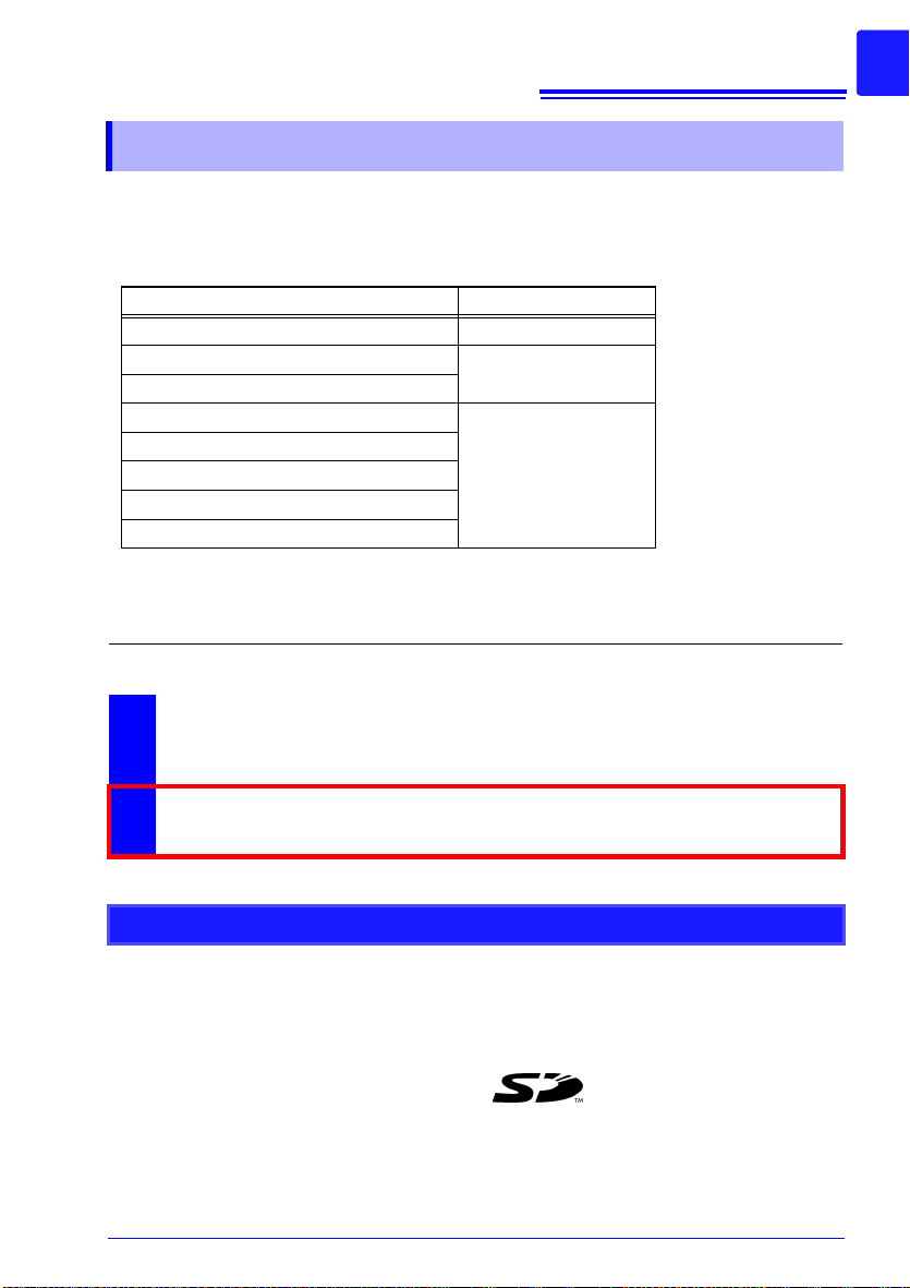
This document uses the following device names:
Product Name in this document
LR8410-20 Wireless Logging Station The instrument
LR8510 Wireless Voltage/Temp Unit
LR8511 Wireless Universal Unit
LR8512 Wireless Pulse Logger
LR8513 Wireless Clamp Logger
LR8514 Wireless Humidity Logger
LR8515 Wireless Voltage/Temp Logger
LR8520 Wireless Fungal Logger
The following documents are provided with this instrument. Refer to them as
appropriate for your application.
Document Description
Measurement unit
Wireless logger
1
Measurement
1
Guide
Instruction Manual
2
(This document)
Read first.
Offers an introduction to the instrument’s basic measuring method for
first time users.
Contains explanation and instructions regarding the instrument's operating method and functions.
Trademarks
• Microsoft and Windows are either registered trademarks or trademarks of Microsoft Corporation in the United States and other countries.
• Bluetooth® is a registered trademark of Bluetooth SIG, Inc.(USA).
The trademark is used by HIOKI E.E. CORPORATION under license.
• The SD logo is a trademark of SD-3C, LLC.
• Sun, Sun Microsystems, Java, and any logos containing Sun or Java are trademarks or
registered trademarks of Oracle Corporation in the United States and other countries.
2
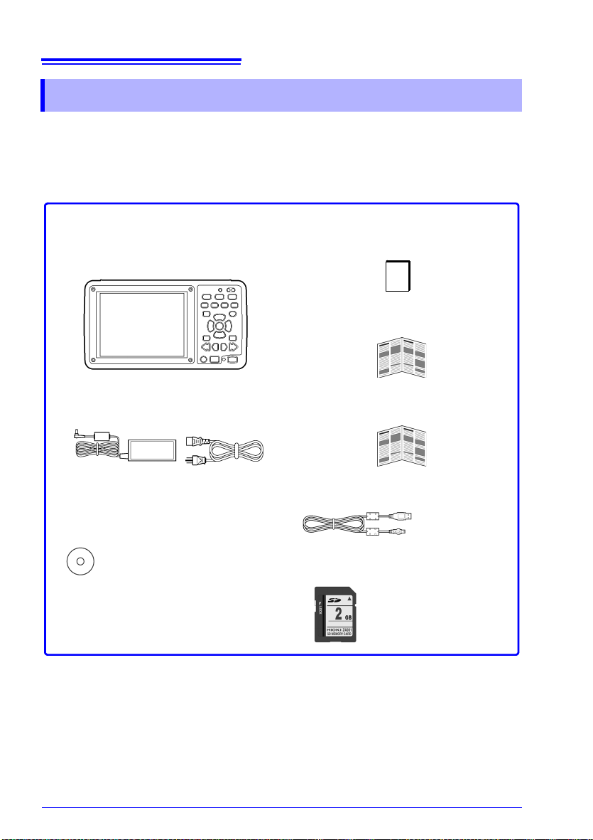
Confirm that these contents are provided.
LR8410-20 Wireless Logging Station
........................................................... 1
Z1008 AC Adapter............................ 1
Logger Utility(Data acquisition appli-
cation program CD) ......................... 1
(p. 44)
The latest version can be downloaded from our web site.
Instruction manual ...........................1
Measurement guide..........................1
Precautions Concerning Use of
Equipment That Emits Radio Waves.. 1
USB Cable.........................................1
Z4001 SD Memory Card (2 GB) .......1
(p. 182)
Confirming Package Contents
Confirming Package Contents
When you receive the instrument, inspect it carefully to ensure that no damage
occurred during shipping. In particular, check the accessories, panel switches, and
connectors. If damage is evident, or if it fails to operate according to the specifica
tions, contact your authorized Hioki distributor or reseller.
-
Confirming Package Contents
Instruction manual
LR8410-20
Measurement units
(Up to 4)
Accessories, etc.
Options
Contact your authorized Hioki distributor or reseller for details.
LR8510 Wireless Voltage/Temp Unit Z1007 Battery Pack
LR8511 Wireless Universal Unit Z1008 AC Adapter
LR8512 Wireless Pulse Logger C1007 Carrying Case
LR8513 Wireless Clamp Logger Z1009 Fixed Stand
LR8514 Wireless Humidity Logger 9642 LAN Cable
LR8515 Wireless Voltage/Temp Logger Z4001 SD Memory Card (2 GB)
LR8520 Wireless Fungal Logger Z4003 SD Memory Card (8 GB)
P9000-01 Differential Probe
P9000-02 Differential Probe
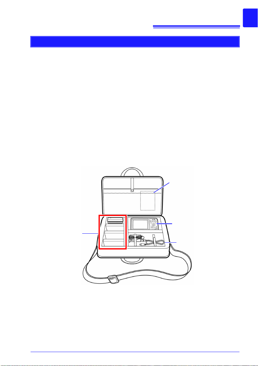
Storing the instrument and measurement units in the C1007 Carrying Case
Store the instrument and measurement units in the C1007 Carrying Case as shown below.
3
4
Safety Information
Safety Information
This instrument and measurement units are designed to comply with IEC 61010 Safety
Standards, and has been thoroughly tested for safety prior to shipment. However, mishan
dling during use could result in injury or death, as well as damage to the instrument and
measurement units. Using the instrument and measurement units in a way not described
in this manual may negate the provided safety features.
Be certain that you understand the instructions and precautions in the manual before
use. We disclaim any responsibility for accidents or injuries not resulting directly from
instrument and measurement units defects.
Please carefully review all safety information about the wireless logger in the
Measurement Guide.
Mishandling during use could result in injury or death, as well as damage to the instrument. Be certain that you understand the instructions
and precautions in the manual before use.
With regard to the electricity supply, there are risks of electric shock,
heat generation, fire, and arc discharge due to short circuits. If persons
unfamiliar with electricity measuring instruments are to use the instru
ment, another person familiar with such instruments must supervise
operations.
Safety Symbols
-
-
In the manual, the symbol indicates particularly important information that the user
should read before using the instrument.
The symbol printed on the instrument indicates that the user should refer to a corresponding topic in the manual (marked with the symbol) before using the relevant
function.
Indicates a high voltage hazard.
If a particular safety check is not performed or the instrument is mishandled, this may
give rise to a hazardous situation; the operator may receive an electric shock, may get
burnt or may even be fatally injured.
Indicates a double-insulated device.
Indicates a grounding terminal.
Indicates DC (Direct Current).
The following symbols in this manual indicate the relative importance of cautions and
warnings.
Indicates that incorrect operation presents an extreme hazard that could result in
serious injury or death to the user.
Indicates that incorrect operation presents a significant hazard that could result
in serious injury or death to the user.
Indicates that incorrect operation presents a possibility of injury to the user or
damage to the instrument and measurement units.
Indicates advisory items related to performance or correct operation of the instrument and measurement units.
Symbols for Various Standards
Li-ion
Indicates that the product conforms to regulations set out by the EU Directive.
FCC ID
Indicates the ID number of the wireless module certified by the U.S. Federal Communications Commission (FCC).
IC Indicates the number of the wireless module certified by Industry Canada.
This is a recycle mark established under the Resource Recycling Promotion Law
(only for Japan).
Indicates the Waste Electrical and Electronic Equipment Directive (WEEE Directive)
in EU member states.
Other Symbols
Indicates the prohibited action.
5
Safety Information
(p. )
[ ]
Indicates the location of reference information.
Indicates that descriptive information is provided below.
*
The names of setting objects and buttons on the screen are indicated by square
brackets [ ].
SET
(Bold
charac
ters)
• Unless otherwise specified, “Windows” represents Windows XP, Windows Vista, Windows 7,
Windows 8, and Windows 10.
• Dialog box represents a Windows dialog box.
• Click: Press and quickly release the left button of the mouse.
• Double click: Quickly click the left button of the mouse twice.
Bold characters within the text indicate operating key labels.
-
Accuracy
We define measurement tolerances in terms of f.s. (full scale), rdg. (reading) and dgt.
(digit) values, with the following meanings:
f.s.
(maximum display value or
scale length)
rdg.
(reading or displayed value)
dgt.
(resolution)
The maximum displayable value or scale length. This is usually the
name of the currently selected range. Example: For the 1 V range,
f.s. = 1 V
The value currently being measured and indicated on the measuring instrument.
The smallest displayable unit on a digital measuring instrument,
i.e., the input value that causes the digital display to show a "1" as
the least-significant digit.
6
Safety Information
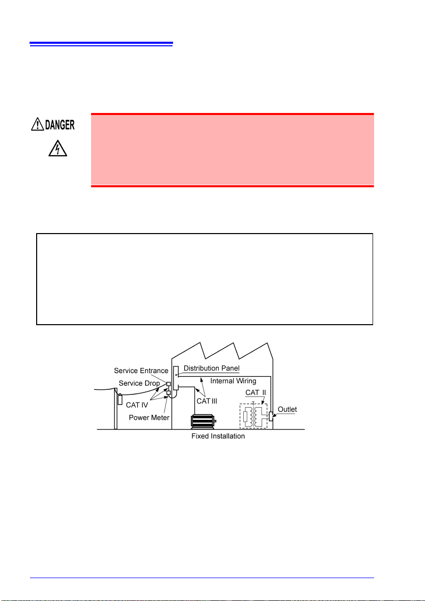
Measurement categories
To ensure safe operation of measurement instruments, IEC 61010 establishes safety
standards for various electrical environments, categorized as CAT II to CAT IV, and called
measurement categories.
• Using a measuring HiLogger in an environment designated with a
higher-numbered category than that for which the HiLogger is rated
could result in a severe accident, and must be carefully avoided.
• Never use a measuring HiLogger that lacks category labeling in a
CAT II to CAT IV measurement environment. Doing so could result
in a serious accident.
Hioki LR8510 Wireless Voltage/Temp Unit and LR8511 Wireless Universal Unit complies
with CAT II (300 VAC, DC) safety requirements.
CAT II:
CAT III:
CAT IV:
When directly measuring the electrical outlet receptacles of the primary electrical
circuits in equipment connected to an AC electrical outlet by a power cord
(portable tools, household appliances, etc.).
When measuring the primary electrical circuits of heavy equipment (fixed
installations) connected directly to the distribution panel, and feeders from the
distribution panel to outlets.
When measuring the circuit from the service drop to the service entrance, and to
the power meter and primary overcurrent protection device (distribution panel).
Operating Precautions
Operating Precautions
Follow these precautions to ensure safe operation and to obtain the full benefits of
the various functions.
Please carefully review all safety information about the wireless logger in
the Measurement Guide.
Bluetooth
The Wireless Voltage/Temp Unit, Wireless Universal Unit, and Wireless Logging Station
use the 2.4 GHz frequency band. No radio station license is required in order to use the
product, but the following precautions should be observed:
• Do not use with systems required to exhibit a high level of safety or reliability.
• Do not use in proximity to pacemakers or other medical devices.
• Do not attempt to modify or disassemble.
• When used in proximity to other devices that use the same frequency
band, for example wireless networking devices, transmission and recep
tion of data may become unstable, or the product may be affected by the
other devices.
• The line-of-sight communications range between the Wireless Logging
Station and the Wireless Voltage/Temp Unit and Wireless Universal Unit
is 30 m. Obstructions (such as walls or metal shielding) may cause com
munications to become unreliable and/or reduce the communications
range.
• Although communications between the Wireless Voltage/Temp Unit and
Wireless Universal Unit and the Wireless Logging Station are encrypted
using SSP, this does not guarantee the integrity or secrecy of transmitted
data. Hioki is not liable for the electronic interception or unauthorized dis
closure by other means of measured values sent via wireless communications.
• The Wireless Voltage/Temp Unit, Wireless Universal Unit, and Wireless
Logging Station emit radio waves. Use of radio waves is subject to
licensing requirements that are specific to the country of use, and use of
these products in areas other than the countries listed in the provided
“Precautions Concerning Use of Equipment That Emits Radio Waves”
may constitute a violation of applicable law, resulting in fines or other
penalties.
7
-
-
-
To facilitate stable transmission and reception of data, the product should
be positioned away from the floor, for example on a stand, rather than
close to the floor.
8
Operating Precautions
Before Use
• Before using the instrument the first time, verify that it operates normally to ensure that no
damage occurred during storage or shipping. If you find any damage, contact your authorized Hioki distributor or reseller.
• Before using the instrument, make sure that the insulation on the cables is undamaged and
that no bare conductors are improperly exposed. Using the instrument in such conditions
could cause an electric shock, so contact your authorized Hioki distributor or reseller for
replacements.
Installation
LR8410-20 Wireless Logging Station
Operating temperature and humidity:
Temperature:-10°C to 50°C, Humidity:30 to 80%RH(non-condensating)
(Charging temperature range: 5°C to 35°C)
LR8510 Wireless Voltage/Temp Unit, LR8511 Wireless Universal Unit
Operating temperature and humidity:
Temperature: -20°C to 60°C
Humidity: -20°C to 40°C, 80%RH or less(non-condensating)
40°C to 45°C, 60%RH or less(non-condensating)
45°C to 50°C, 50%RH or less(non-condensating)
50°C to 60°C, 30%RH or less(non-condensating)
(Charging temperature range: 5°C to 35°C)
Temperature and humidity range for guaranteed accuracy:
Temperature:23±5°C, Humidity 80%RH or less(non-condensating)
• Avoid temperature changes around the terminal block. Especially avoid
directed airflow such as from an electric fan or air conditioner vent.Ther
mocouple inputs are prone to measurement errors.
• When the instrument is moved to a location with significantly different
ambient temperature, allow at least 60 minutes for thermal equalization
before measuring.
-
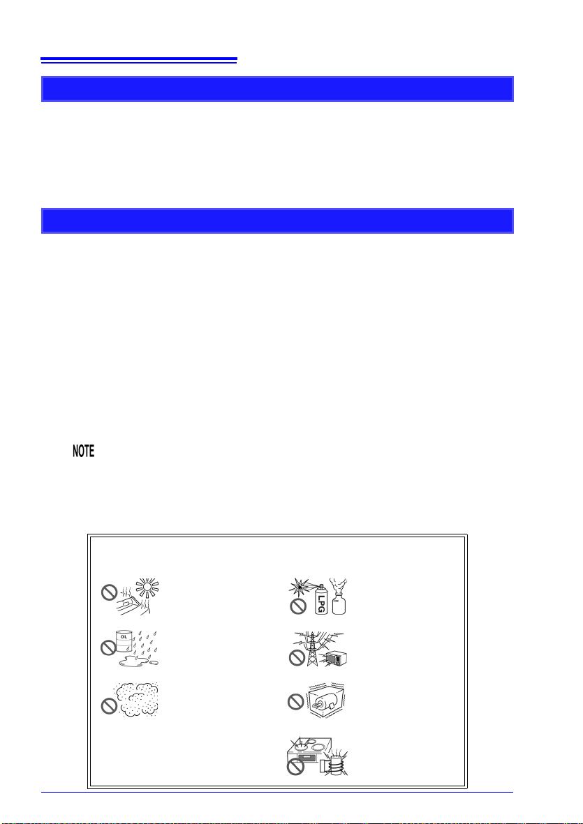
Avoid the following locations that could cause an accident or
damage to the instrument and measurement units.
Exposed to direct sunlight
Exposed to high temperature
Exposed to water, oil, other
chemicals, or solvents
Exposed to high humidity
or condensation
Exposed to high levels of
particulate dust
In the presence of corrosive or explosive gases
Exposed to strong electromagnetic fields
Near electromagnetic radiators
Subject to vibration
Near induction heating
systems
(e.g., high-frequency induction heating systems
and IH cooking utensils)
Handling the Instrument
To avoid electric shock, do not remove the instrument's case. The
internal components of the instrument carry high voltages and may
become very hot during operation.
Touching any of the high-voltage points inside the instrument is very
dangerous.
Do not attempt to modify, disassemble or repair the instrument; as
fire, electric shock and injury could result.
To avoid damage to the instrument, protect it from physical shock when
transporting and handling. Be especially careful to avoid physical shock
from dropping.
This instrument and measurement units may cause interference if used in
residential areas.Such use must be avoided unless the user takes special
measures to reduce electromagnetic emissions to prevent interference to
the reception of radio and television broadcasts.
Handling the Cords and Cables
• Avoid stepping on or pinching cables, which could damage the cable
insulation.
• To avoid breaking the cables, do not bend or pull them.
• To avoid damaging the power cord, grasp the plug, not the cord, when
unplugging it from the power outlet.
9
Operating Precautions
Before Turning Power On
Before turning the instrument on, make sure the supply voltage
matches that indicated on the AC adapter. Connection to an improper
supply voltage may damage the instrument or AC adapter and pres
ent an electrical hazard.
When the power is turned off, do not apply voltage or current to the measurement units. Doing so may damage the measurement units.
• After use, always turn OFF the power.
• Brief power interruptions of 40 ms or less will not cause this instrument
and measurement units to malfunction. However, Longer interruptions
may cause the instrument to shut itself off, so consider local power con
ditions before installing, as appropriate.
• To ensure that recording is not interrupted by power outages, you can
use the Z1008 AC Adapter and Z1007 Battery Pack together.
-
-

10
Operating Precautions
Using the Battery Pack
If handled or used improperly, the battery pack may leak, become excessively hot, catch on
fire, crack, or suffer other damage. Please observe the following precautions.
• Use the Z1007 Battery Pack with the instrument and measurement
units. Use of other battery packs may damage the device or cause
an accident. Hioki is not liable for such damage.
See: "2.1 Using the Battery Pack (Option)" (p. 41)
• Do not attempt to disassemble or modify the battery pack. The battery pack incorporates safety mechanisms and protective devices
to prevent dangerous operation. If these are damaged, the battery
pack may leak, become excessively hot, generate smoke, crack, or
catch on fire.
• Do not connect the battery pack’s positive and negative terminals
with wire or other metallic objects. Do not carry or store the battery
pack together with metal necklaces, hairpins, or other metal
objects. Doing so may short the battery pack, causing an excessively large current to flow; the battery to leak, become excessively
hot, generate smoke, crack, or catch on fire; or the wire, necklace,
hairpin, or other metal object to become excessively hot.
• Do not submerge the battery pack in water or heat it. Doing so may
melt the insulation, damage the gas release valve or other safety
devices, cause the electrolyte to ignite, or cause the battery to leak,
become excessively hot, generate smoke, crack, or catch on fire.
• Do not use or leave the battery pack near a flame or heater or in any
other hot location (80°C or hotter). If the resin separator becomes
damaged by heat, the battery may experience an internal short,
causing it to leak, become excessively hot, generate smoke, crack,
or catch on fire.
• Do not place the battery pack in, or expose it to, water, seawater, or
any other liquid. Damage to safety devices in the battery pack may
allow the battery to charge at an abnormal current or voltage, causing an abnormal chemical reaction inside the battery pack and
causing it to leak, become excessively hot, generate smoke, crack,
or catch on fire.
• Do not pierce the battery pack with wire, strike it with a hammer, or
step on it. Doing so may damage or deform the battery pack so that
internal components are shorted, causing it to leak, become excessively hot, generate smoke, crack, or catch on fire.

11
Operating Precautions
• Do not subject the battery pack to strong mechanical shock or
throw it. Doing so may cause it to leak, become excessively hot,
generate smoke, crack, or catch on fire. Damage to safety devices
in the battery pack may allow the battery to charge at an abnormal
current or voltage, causing an abnormal chemical reaction inside
the battery pack and causing it to leak, become excessively hot,
generate smoke, crack, or catch on fire.
• Do not use battery packs that have suffered external damage or
become deformed in shape due to having been dropped or for other
reasons. Doing so may cause the battery pack to leak, become
excessively hot, generate smoke, crack, or catch on fire.
• Do not solder directly to the battery pack. The resulting heat may
melt the insulation, damage the gas release valve or other safety
devices, cause the electrolyte to ignite, or cause the battery to leak,
become excessively hot, generate smoke, crack, or catch on fire.
• Using this battery pack in devices other than those designated by
Hioki may degrade its performance or service life, and some
devices may trigger an abnormal current flow or damage the battery pack, causing it to leak, become excessively hot, generate
smoke, crack, or catch on fire.
• If you get fluid that has leaked from the battery pack in your eyes,
avoid rubbing them and immediately flush with a large volume of
tap water or other clean water. Seek immediate medical attention.
Failure to do so may cause permanent vision damage.
• If the battery pack fails to charge fully even though the normal
charge time has elapsed, unplug the AC adapter from the instrument or measurement unit to stop charging. Failure to do so may
cause the battery pack to leak, become excessively hot, generate
smoke, crack, or catch on fire.
• Do not place the battery pack on top of an electromagnetic range or
inside a microwave oven or pressure cooker. Doing so may heat the
battery pack rapidly or break its airtight seal, causing it to leak,
become excessively hot, generate smoke, crack, or catch on fire.
• If the battery pack starts to leak or emit an unusual odor, move it
away from fire immediately. Failure to do so may ignite the leaked
electrolyte and cause the battery pack to generate smoke, crack, or
catch on fire.
• If you notice the battery pack emitting an unusual odor, changing
color, becoming deformed in shape, or otherwise exhibiting a different appearance than usual while it is being used, charged, or
stored, immediately halt use and contact your authorized Hioki distributor or reseller. Continued use may cause the battery pack to
leak, become excessively hot, generate smoke, crack, or catch on
fire.

12
Operating Precautions
• Do not use or leave the battery pack in a hot location, for example in a
place that is exposed to strong, direct sunlight or inside a closed vehicle
on a hot summer day. Doing so may cause it to leak, become exces
sively hot, or generate smoke. It may also degrade the battery pack’s
performance or service life.
• If the battery leaks onto your skin or clothing, immediately rinse with a
large volume of tap water or other clean water. Failure to do so may
result in a skin rash.
• If you notice rust, an unusual odor, excessive heat, or any other abnormal state upon using the battery for the first time after purchase, stop use
and contact your HIOKI distributor.
• Check the battery pack’s positive and negative terminals and connect
them properly to the instrument or measurement unit.
• Always charge the battery before using it for the first time after purchase
or after it has been stored for an extended period of time.
• Keep the ambient temperature between 5°C and 35°C while charging the
battery pack. When charging at low temperatures near 5°C, the battery
pack will hold less charge than when charged at 23°C. The lower the
temperature, the shorter the time the battery pack will power the device.
• The battery pack’s service life (defined as the ability to retain 70% or
more of its initial capacity) is approximately 300 charge/discharge cycles.
(Service life varies with the method of storage and operating environment.)
• When storing for an extended period of time, remove the battery pack
from the instrument or measurement unit and store in a cool place (about
20°C). Charge the battery pack for approximately 30 minutes once every
year in an instrument or measurement unit.
• The battery pack is a consumable. Degraded operating times following
proper charging indicate that the battery pack has reached the end of its
service life. Replace it with a new battery pack.
-
When transporting the Z1007 Battery Pack on an aircraft
• The Z1007 Battery Pack uses a rechargeable lithium-ion battery.
• Transport of lithium-ion batteries on aircraft is subject to restrictions based on UN recommendations.
• Before repairing or calibrating devices that use the Z1007 Battery Pack or transporting
them on an aircraft, contact your authorized Hioki distributor or reseller.

Using the AC Adapter
• Use only the supplied Model Z1008 AC Adapter. AC adapter input
voltage range is 100 to 240 VAC (with ±10% stability) at 50/60 Hz. To
avoid electrical hazards and damage to the instrument and measurement units, do not apply voltage outside of this range.
• When connecting the AC adapter to the instrument, a measurement
unit, or a power outlet, always turn off the instrument and measurement unit first.
• To avoid electrical accidents and to maintain the safety specifications of this instrument and measurement units, connect the supplied power cord only to a 3-contact (two-conductor + ground)
outlet.
Turn off the power before disconnecting the AC adapter.
13
Operating Precautions

14
Operating Precautions
Handling of temperature and humidity sensor
Model Z2000 Humidity Sensor and Model Z2010/Z2011 Humidity Sensor
are not dustproof or waterproof. Do not use the sensor in locations where
it may be exposed to dust or water. It may cause a malfunction of the
instrument.
• Sensor sensitivity and precision will degrade over time, even under normal operating conditions. To maintain the instrument’s ability to make
measurements that conform to the accuracy specifications, it is recom
mended to replace the temperature and humidity sensor with a new unit
once it has been used for one year after being opened.
• When the sensor is used outside the specified operating (storage) environment, the sensor accuracy may deteriorate even within the 1 year
accuracy warranty period and accurate measurement cannot be per
formed.
• In principle, the surface of the instrument’s temperature and humidity
sensor may become contaminated if exposed to an environment contain
ing organic gases (ketone, acetone, ethanol, toluene, etc.), increasing
the error component of humidity measurement.
• Do not expose the temperature and humidity sensor to any concentrated
chemical solvent for an extended period of time while it is used or stored.
• The sensor may become contaminated by organic gases released from
some types of vinyl chloride and packaging material.
• When the temperature and humidity sensor is not used, place it with a
drying agent in a plastic bag, seal the bag completely, and store it in a
cool, dark place.
• Do not allow any condensation to form. Condensation can form particularly in any environment where the temperature changes drastically.
• This instrument does not come with a guarantee against any problem
when the sensor is used outside the specified operating (storage) envi
ronment.
• Change in humidity (lower to higher, or higher to lower) affects measured
humidity values due to hysteresis. For the Z2000 Humidity Sensor, an
arithmetic difference of about 3%RH will arise; for the Z2010/Z2011
Humidity Sensor, an arithmetic difference of ±1%RH or narrower will
arise.
-
-
-
-

Operating Precautions
Connection Precautions
When connecting measurement cables to a Wireless Voltage/Temp Unit or
Wireless Universal Unit
Do not leave the Unit connected to test objects in environments
where a voltage surge might exceed the dielectric withstand voltage.
Doing so could result in damage to the measurement units, bodily
injury or fatal accident.
• To avoid electric shock or a short-circuit accident, disconnect
power to the measurement line before turning on the measurement
unit.
• To avoid shock and short circuits, turn off all power before connecting measurement cables.
• Do not connect a cable to the measurement units while it is connected to the object to be measured. Otherwise, an electric shock
accident may occur.
• To avoid short-circuit accidents, make certain that connections are
secure.
• To avoid electric shock and short-circuit accidents, always close
the analog input terminal cover and tighten the screws.
• To avoid electric shock, use the recommended wire type to connect
to the current input terminals, or otherwise ensure that the wire
used has sufficient current handling capacity and insulation.
• Measurement units are not drip-proof and should be installed so
that water or other liquids cannot flow down measurement cables
and enter the unit enclosure via the terminal block. One way to do
so is to orient the unit so that the measurement cables are lower
than the unit.
15
16
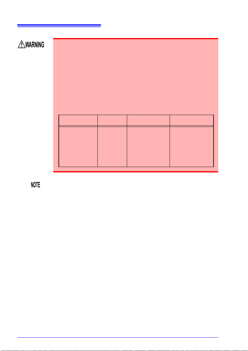
Input and Output
Terminals
Maximum
Input Voltage
Maximum rated
voltage to earth
Max. Inter-Channel
Voltage
Analog Input
Terminals
(both Voltage/
Temp Unit, and
Universal Unit)
±100 VDC 300 V AC,DC
300 VDC,
However, channels
are not isolated
when using resistance thermometer
sensors and during
resistance or humidity measurement.
Operating Precautions
• The following table lists the analog input terminals’ maximum input
voltage, input-to-ground maximum rated voltage, and channel-tochannel maximum rated voltage for each unit.To avoid electric shock
accidents and damage to the instrument and measurement units, do
not exceed these voltages.
• Channels are insulated by semiconductor relays. When a voltage
beyond the specification is applied between the channels, the semiconductor relay may short circuit. Please ensure that a voltage beyond
specification, especially a surge such as a lightning, is never applied.
When an abnormal measurement value is observed, please contact
your authorized Hioki distributor or reseller for inspection.
• When connecting a measurement cable of 3 m or more in length, the
cable may experience external noise or other EMC effects.
• Route measurement leads and cables as far away as possible from
power and earth lines.
• Measurement values may be scattered if the leads are routed in parallel
with other devices. If they must be parallel, check operation before taking
measurements.
17
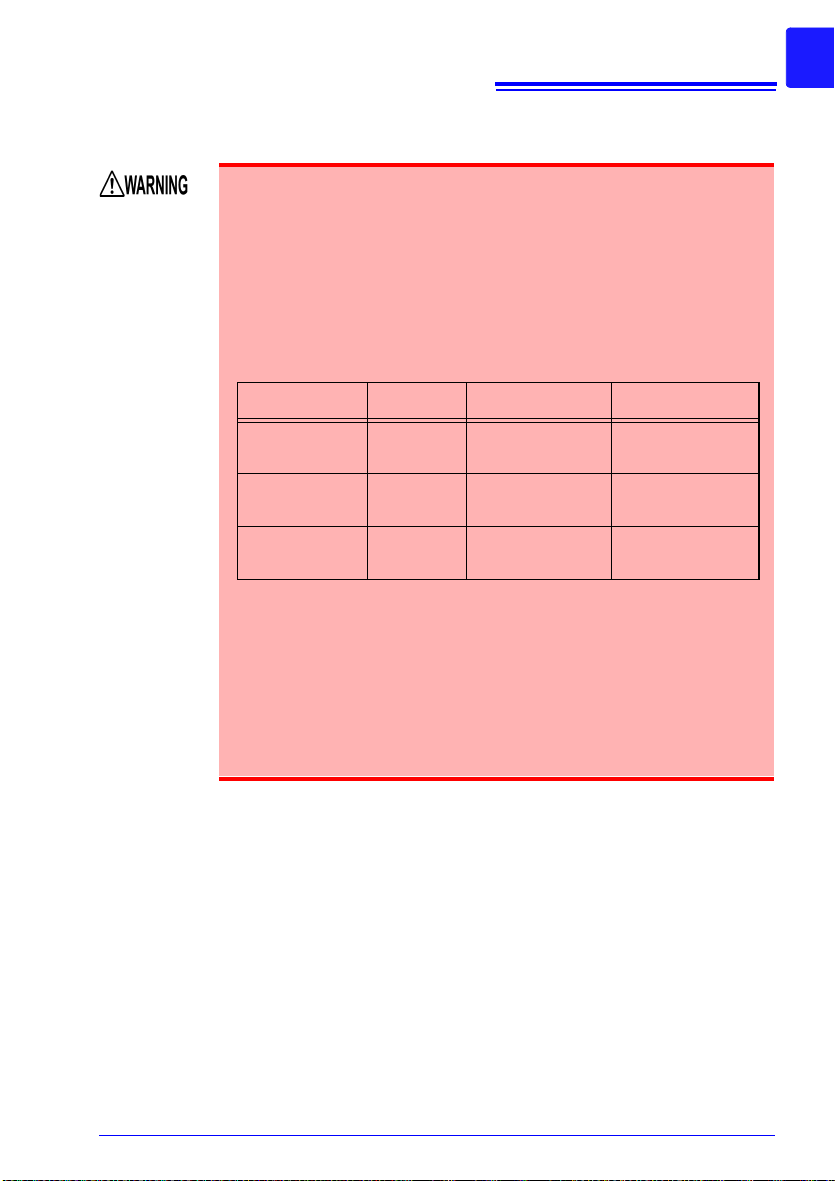
Input and Output
Terminals
Maximum
Input Voltage
Maximum rated
voltage to earth
Max. Inter-Channel
Voltage
Alarm Output
Terminals
Non-Isolated
(instrument/GND
Common)
Non-Isolated
(instrument/GND
Common)
External Trigger
(EXT.TRIG)
Terminal
0 to 10 VDC
Non-Isolated
(instrument/GND
Common)
Trigger Output
(TRIG.OUT)
Terminal
Non-Isolated
(instrument/GND
Common)
Operating Precautions
When connecting to the instrument’s alarm output terminals or external control terminal
• To avoid electric shock or damage to the instrument, always
observe the following precautions when connecting to alarm output
terminals and External Control Terminals.
• Always turn off the power to the instrument and to any devices to
be connected before making connections.
• Ensure that devices and systems to be connected to the External
Control Terminals are properly isolated.
• Be careful to avoid exceeding the ratings of External Control Terminals.
• Never apply voltage to the Alarm output terminals and TRIG OUT
terminals. The instrument will be damaged.
• The grounds for the Alarm output, EXT TRG and TRIG OUT terminals are common with the instrument grounds (GND), and are not
isolated. To avoid damaging the instrument, connect wiring so as to
avoid any potential difference between the grounds of the Alarm
output, EXT TRIG and TRIG OUT terminals and connected devices
(or system).

18
Operating Precautions
Using a SD memory card/USB flash drive
• Store SD memory cards and USB flash drives out of reach of children to prevent accidental ingestion.
• Do not modify, disassemble, or repair SD memory cards or USB
flash drives. Doing so may result in fire, electric shock, or injury.
• Inserting a SD memory card/USB flash drive upside down, backwards or in
the wrong direction may damage the SD memory card, USB flash drive, or
instrument.
• Never eject a SD memory card/USB flash drive while measuring or when
the instrument is accessing the card. Data on the SD memory card/USB
flash drive may be destroyed. (The SD icon/USB flash drive icon at the
lower left is red while the card is being accessed.)
• Do not transport the instrument while a USB flash drive is connected.
Damage could result.
• As the SD memory card/USB flash drive is sensitive to static electricity,
damage to the SD memory card/USB flash drive or wrong operations by
the instrument may occur due to static electricity. Please be careful when
handling it.
• With some USB flash drives, the instrument may not start up if power is
turned on while the USB flash drive is inserted. In such a case, turn
power on first, and then insert the USB flash drive. It is recommended to
try out operation with a USB flash drive before starting to use it for actual
measurements.
• Use USB flash drives within the specified temperature and humidity
range.
• Using SD memory cards or USB flash drives while there is moisture on
their terminals may result in fire or electric shock.
• Do not apply labels or other adhesives to SD memory cards. Doing so
may cause them to become excessively hot or catch on fire.
 Loading...