

Hioki LR8400-20, LR8401-20, LR8402-20 Instruction Manual

Instruction Manual
LR8400-20
LR8401-20
LR8402-20
MEMORY HiLOGGER
July 2014 Revised edition 7 LR8400B980-07 14-07H

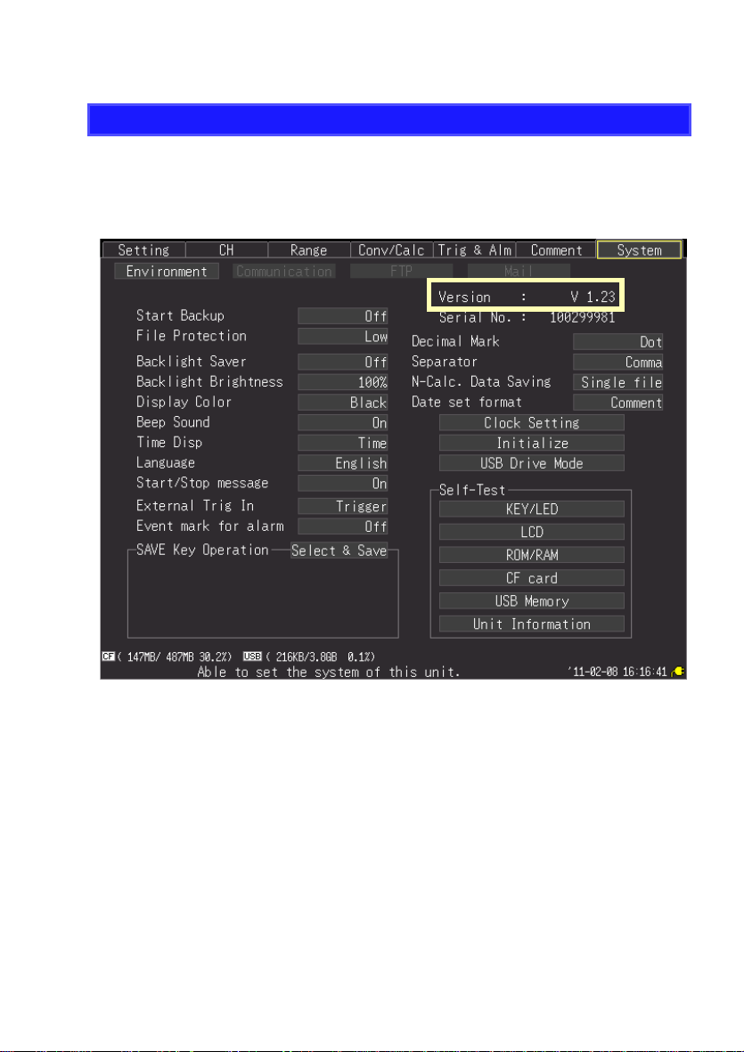
HiLogger Firmware Version Information and Upgrades
LAN communication is available with HiLogger firmware version 1.20 and later.
(The release date for version 1.20 is June, 2010.)
The HiLogger firmware version is displayed at the upper right on the System screen.
The latest version can be downloaded from Hioki’s website.
Please visit our company’s website or contact your dealer or Hioki representative for the
version upgrade procedure.


Contents
Introduction ..............................................................................1
Confirming Package Contents................................................2
Safety Information....................................................................3
Operating Precautions.............................................................6
Chapter 1
Overview ____________________________________13
1.1 Product Overview and Features .............................13
1.2 Measurement Flow ........... .......................................14
1.3 Names and Functions of Parts, Screen
Configurations .......................... ............................... 16
1.4 Basic Operation .......................................................22
Screen Operations (changing settings, scrolling waveforms,
and displaying values) ......................................................22
Starting and Stopping Measurement ................................23
Disabling Key Operations (Key-Lock Function) ...............25
Performing Zero Adjustment ............................................25
Saving Data ......................................................................25
Confirming Inputs (Monitor) ..............................................2 6
i
Contents
1
2
Chapter 2
Measurement Preparations_________________27
2.1 Attaching Expansion Input Units (as needed) ......28
2.2 Using the Battery Pack (Option) ............................30
Install the Battery Pack ....................................................30
Charge the Battery Pack ..................................................31
2.3 Connecting the AC Adapter .................................. ..32
2.4 Making Connections ...............................................33
Pre-Connection Inspection ...............................................33
Voltage and Thermocouple Temperature Measurement .34
Temperature Measurement with a Resistance Temperature
Detector (RTD) .................................................................36
Humidity Measurement ....................................................37
Resistance Measurement ................................................39
Pulse Measurement .........................................................40

ii
Contents
Connecting Alarm Outputs ...............................................41
+12 V Output Connection (for external sensors) ..............42
External Control (using TRIG OUT and EXT TRIG) ........43
2.5 Turning the Power On and Off ............................... 44
2.6 Inserting a CF Card or USB Flash Drive
(when saving data) ................................................. 45
CF Card Insertion & Removal ..........................................46
USB flash drive Insertion & Removal ...............................46
Formatting a CF Card/USB flash drive ............................47
2.7 Compensating for Input Circuit Offset
(Zero Adjustment) .......... .. ... .................................... 48
Chapter 3
Settings_____________________________________ 49
3.1 Setting Flow Overview ........................................... 49
3.2 Configuring Measurement Settings ...................... 50
Time Setting by Key Operations ......................................50
3.3 Input Channel Settings .......... ................................. 53
Key Setting Procedure .....................................................53
Voltage Measurement Settings ........................................55
Temperature Measurement Settings (using thermocouples) 56
Temperature Measurement Settings (for RTDs) .............58
Humidity Measurement Settings ......................................59
Resistance Measurement Settings ..................................60
Pulse or Logic Measurement Settings .............................61
Integration (Count) Measurement Settings ......................62
Revolution Measurement Settings ...................................63
3.4 Data Saving Settings .............................................. 64
3.5 Waveform Display Settings (as needed) .............. 65
Key Setting Procedure .....................................................65
Selecting Waveform Display Color ..................................65
Specifying Vertical Display Range by Magnification and
Zero Position (vertical axis expansion/compression) .......66
Specifying the Vertical Display Range by Upper and
Lower Limits (expansion/compression) ............................67
Setting the Display Time Base
(horizontal axis magnification) .........................................68
3.6 Scaling Settings (as needed) ................................. 69

3.7 Entering Titles and Comments (as needed) ..........71
3.8 Suppressing Noise (Enable Digital Filtering) ........73
3.9 Viewing and Editing with the All-Channel
Settings List .............................................................74
Batch Copying Channel Settings .....................................75
Batch Setting Waveform Display/Hide and Waveform
Color Settings for All Channels ........................................76
Initializing Settings (to factory defaults) ............................77
Aligning Zero Positions on the Grid ..................................78
Setting CH1 of UNIT1 Value as a Scaling Value
(Inter-Channel Compensation function) ...........................79
iii
Contents
2
3
4
Chapter 4
Observing Measurements and Data ________83
4.1 Confirming Measured Values, and Starting
Measurement ...........................................................83
4.2 Observing Waveforms ............................................85
Displaying Waveforms (Display Descriptions) .................85
Displaying Gauges ...........................................................86
Viewing Input Signals as Numerical Values .....................87
Scrolling Waveforms ........................................................88
Verifying Waveform Display Position ...............................88
Magnifying and Compressing Horizontally .......................89
Viewing Any Waveform Location (Jump Function) ..........89
Specifying a Waveform Time Span ..................................90
Displaying Cursor Values .................................................91
4.3 Marking Waveforms and Searching Marks
(Search Function) ....................................................93
Inserting Event Marks While Viewing Waveforms ............93
Inserting Event Marks Using External Input Signals ........94
Alarm Event Marks ...........................................................95
How are event marks handled in text (CSV) conversion? 96
Searching Event Marks ....................................................97
Chapter 5
Specifying Criteria for Measurements ____ __99
5
About Triggering ...............................................................99
5.1 Triggering Measurement Start and Stop .. ... .. ... ...100

iv
Contents
Types of Trigger Criteria ................................................100
Enable the Trigger Function ...........................................101
Key Setting Procedure ...................................................101
Setting Trigger Criteria ...................................................102
Selecting Triggering Criteria (Trigger Source) ...............105
Using External Triggering ..............................................106
Setting Criteria for Pre-Trigger Measuring (Pre-Trig) .....108
5.2 Alarm Output ......................................................... 109
Checking Alarm Criteria .................................................109
Alarm Settings ................................................................111
5.3 Confirming All Trigger and Alarm Criteria Settings 114
5.4 Periodic (Timer) Measurements .......................... 115
5.5 Measurement with Trigger and Timer Functions 117
5.6 Trigger Setting Examples .................................... 119
Chapter 6
Saving & Loading Data ____________________121
6.1 About Saving and Loading Data ......................... 121
What happens to data in a power outage? ....................123
Preparation for power outages during long-term
measurements ............................................................... 123
6.2 Saving Data ........................................................... 124
Automatic Saving (Waveform Data and Numerical
Calculation Results) ............................................................. 125
Replacing Removable Storage During Real-Time Saving .127
Saving Manually (Waveform Data, Screen Images,
Numerical Calculation Results) ......................................128
To Save a Setting Configuration ....................................131
6.3 Loading Data on the HiLogger ............................ 132
Loading a Setting Configuration .....................................132
Loading Waveform Data and Screen Images ................134
6.4 Data Management ................................................. 135
Switching removable storage .........................................135
Viewing Folder Contents and the Parent Folder ............135
Deleting Data .................................................................136
Renaming Files and Folders ..........................................137
Copying Data .................................................................138
Sorting Files ...................................................................139

Contents
6.5 Transferring Data to a PC (USB Drive Mode) ......140
Select the USB Drive Mode ...........................................140
Connecting the USB Cable ............................................141
Chapter 7
Numerical Calculations/Waveform Calculations
____________________________________________ 143
7.1 Calculate Average, Maximum, Minimum, and Etc. .143
Key Setting Procedure ...................................................144
Real-Time Calculation While Measuring (Auto Calculation) 144
Calculation after Measuring (Manual Calculation) .........146
Apply Calculations to a Specific Time Span
(Manual Calculation Only) ..............................................147
7.2 Numerical Value Calculation Expressions ..........148
7.3 Waveform Calculations .........................................149
Key Setting Procedure ...................................................149
Chapter 8
System Environment Settings ____________ 151
Key Setting Procedure ...................................................152
8.1 Operation Settings ................................................152
Using the Auto-Resume Function
(Resume After Power Restoration) ................................152
File Protection Level Setting ..........................................153
8.2 Screen Key Operation Settings ............................153
Enabling and Disabling the Backlight Saver ..................153
Adjust Backlight Brightness ............................................154
Selecting Black or White Screen Background ................154
Enabling or Disabling the Beeper ...................................154
Selecting the Horizontal (Time) Axis Display .................155
Selecting the Display Language .....................................155
Display of Start/Stop Confirmation Messages ................155
8.3 CSV File Saving Settings ......................................156
CSV File Data Decimal and Separator Characters ........156
Select the sort order for numerical calculation results ...156
Setting How to Handle Date Data Stored in CSV Files ..157
8.4 External Trigger Input Settings .. .. ... .....................157
Selecting the External Trigger Function .........................157
v
5
6
7
8

vi
Contents
Set Alarm Event Marking ...............................................157
8.5 Making System Settings ...................................... 158
Setting the Date and Time .............................................158
Initializing the HiLogger (System Reset) ........................159
Self-Test .........................................................................160
Chapter 9
External Control ___________________________161
9.1 External Trigger Input .......................................... 161
9.2 External Signal Output (Trigger Output) ............ 162
9.3 Alarm Signal Output (Alarm Output) ................... 163
9.4 Synchronous Measurements with
Multiple HiLoggers ............................................... 164
Chapter 10
Connection to a PC(Communication) _____165
Communication Features ...............................................165
10.1 USB Settings and Connections ........................... 166
1. HiLogger Setting ........................................................166
2. Installing the USB Driver ............................................167
3. Connecting the HiLogger to a PC ..............................170
Features Available After USB Setting and Connection ..172
4. Installing the Logger Utility Program ..........................173
Uninstalling the Logger Utility ........................................177
10.2 LAN Settings and Connections
(Before connecting to the network) .................... 178
Things to Check Before Making Settings .......................178
1. PC Network Setup .....................................................180
2. HiLogger Settings ......................................................181
3. Connecting the HiLogger to a PC ..............................184
Features Available After LAN Setting and Connection ..185
When LAN Communication Fails ...................................186
10.3 Using the Logger Utility ...................................... 187
Starting and Ending Logger Utility .................................187
10.4 Remote Measurement with the HTTP Server
Function ................................................................. 188
Displaying the Main Page ..............................................188

Remote Operating ..........................................................189
Start/Stop Measurement ................................................190
Viewing Current Measurement Values ...........................190
Acquiring Data from Internal Memory ............................191
Setting Comments ..........................................................192
10.5 Transferring Data to a PC with the FTP Server
Function .................................................................193
Restricting FTP Server Connections (FTP Authentication) 195
10.6 Auto Sending Data using the FTP Client Function 196
Setting Up an FTP Server on a PC ................................197
HiLogger Auto-Send Settings .........................................211
Testing File Transfer ......................................................214
Checking Communication Status ...................................215
10.7 Sending E-Mail .......................................................216
HiLogger E-Mail Settings ...............................................217
Testing E-Mailing ...........................................................220
Checking Mail Communication Status ...........................221
E-Mail Sending Authentication .......................................222
10.8 About Communications Commands ...................223
Configuring Communications Command Operation .......223
vii
Contents
Chapter 11
Specifications_____________________________ 225
11.1 LR8400-20, LR8401-20, LR8402-20 Memory
HiLogger Specifications .......................................225
11.2 LR8500 Voltage/Temp Unit Specifications ..........240
11.3 LR8501 Universal Unit Specifications .................241
Chapter 12
Maintenance and Service_________________ 243
12.1 Inspection, Repair, and Cleaning .........................243
12.2 Troubleshooting ....................................................244
12.3 Disposing of the HiLogger ....................................246
Removing the Lithium Battery ........................................246
8
9
10
11
12
Appendix
Index

viii
Contents
Appendix____________________________________A1
Appendix 1 Scan Timing .....................................................A1
Appendix 2 Error Messages and Remedial Actions .........A2
Appendix 3 File Naming ......................................................A8
Appendix 4 Text File Internal Format.................................A9
Appendix 5 Binary File Size Calculation..........................A10
Appendix 6 List of Default Settings..................................A11
Appendix 7 Maximum Recordable Time ..........................A12
Appendix 8 Concerning Noise Countermeasures ..........A13
Appendix 9 Frequently Asked Questions........................A19
In sta llation and Settings ..................................................A19
Trigge ring ............................................. ........................... A21
Me asuring .......................................................................A21
Data Saving ....................................................................A23
Logger Utility ...................................................................A25
Appendix 10Introduction to Measurement ApplicationsA26
Measuring Electrical Energy by Pulse Count ..................A26
Connect a 4-20 mA output device and record the average
value every minute ..........................................................A28
Appendix 11Input Circuit Diagram ...................................A30
Index___________________________________Index 1

Introduction
Introduction
Thank you for purchasing the Hioki Model LR8400-20, LR8401-20, LR8402-20 Memory HiLogger.To obtain maximum performance
manual first, and keep it handy for future reference.
from the HiLogger, please read this
1
The following documents are prov
priate for your application.The following documents are provided with this HiLogger. Refer to them as appropriate for your application.
ided with this HiLogger. Refer to them as appro-
Document Description
Measurement
1
Guide
Instruction Manual
2
(This document)
Read first.
Offers an introduction to the HiLogger’s basic measuring method for
first time users.
Contains explanation and instructions regarding the HiLogger's operating method and functions.
Registered Trademarks
• Windows is a registered trademark of Microsoft Corporation in the
United S
• CompactFlash is a registered trademark of Sandisk Corporation
(US
• Sun, Sun Microsystems, Java, and any logos containing Sun or Java
are trademarks or registered trademarks of Sun Microsystems, Inc. in
the United States and other countries.
tates and/or other countries.
A).

2
Confirm that these contents are provided.
LR8400-20, LR8401-20, LR8402-20
Memory HiLogger* .......................... 1
9418-15 AC Adapter......................... 1
with supplied power cord
(p. 32)
Instruction manual (This document)1
Measurement guide..........................1
USB Cable.........................................1
Logger Utility(Data acquisition appli-
cation program CD)..........................1
(p. 141)
The latest version can be downloaded from our web site.
*: LR8400 (with two Model LR8500 Voltage/Temp Unit)
LR8401 (with two Model LR8501 Universal Unit)
LR8402 (with combined units, and UNIT1 is an LR8501 Universal Unit)
Confirming Package Contents
Confirming Package Contents
When you receive the HiLogger, inspect it carefully to ensure that no damage
occurred during shipping. In particular, check the accessories, panel switches, and
connectors. If damage is evident, or if it fails to operate according to the specifications, contact your dealer or
Hioki representative.
Options
Contact your dealer or Hioki represent
LR8500 Voltage/Temp Unit
LR8501 Universal Unit
Z10 00 Battery Pack
941 8-15 AC Adapter
9642 LAN Cable
Z2000 Humidity Sensor
ative for details.
9727 PC Card (256MB)
9728 PC Card (512MB)
9729 PC Card (1GB)
9830 PC Card (2GB)
C1000 Carrying Case
Z5000 Fixed Stand
Safety Information
Safety Information
This HiLogger is designed to comply with IEC 61010 Safety Standards, and has been thoroughly tested for saf
However, mishandling during use could result in injury or death, as
well as damage to the HiLogger. Using the HiLogger in a way not
described in this manual may negate the provided safety features.
Be certain that you understand the instructions and precautions in
the manual before use. We disclaim any responsibility for accidents
or injuries not resulting directly from HiLogger defects.
This manual contains information and warnings essential for safe operation of the
HiLogger and for maintaining it in safe operating condition. Before using it, be sure
to carefully read the following safety precautions.
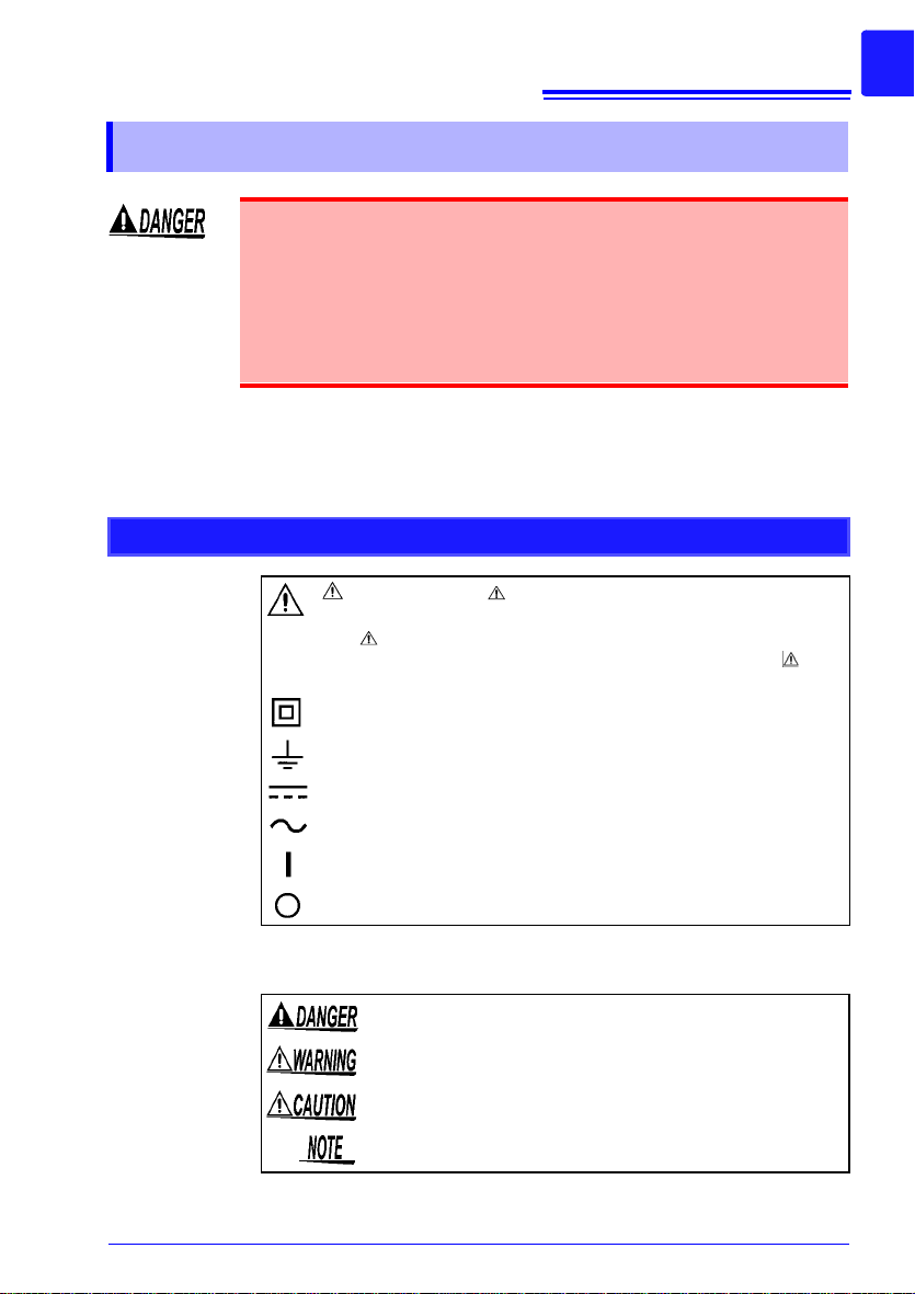
Safety Symbols
In the manual, the symbol indicates particularly important infor-
mation that the user should read before using the HiLogger.
The symbol printed on the HiLogger indicates that the user should
refer to a corresponding topic in
bol) before using the relevant function.
Indicates a double-insulated device.
the manual (marked with the sym-
ety prior to shipment.
3
Indicates a grounding terminal.
Indicates DC (Direct Current).
Indicates AC (Alternatin
Indicates the ON side of the power switch.
Indicates the OFF side of the power switch.
g Current).
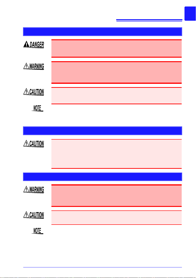
The following symbols in this manual indicate the relative importance of
ns and warnings.
cautio
Indicates that incorrect opera
that could result in serious injury or death to the user.
Indicates that incorrect operation presents a significant hazard
uld result in serious injury or death to the user.
that co
Indicates that incorrect operation pres
to the user or damage to the HiLogger.
Indicates advisory items related to performance or correct
ration of the HiLogger.
ope
tion presents an extreme hazard
ents a possibility of injury
4
Ni-MH
Safety Information
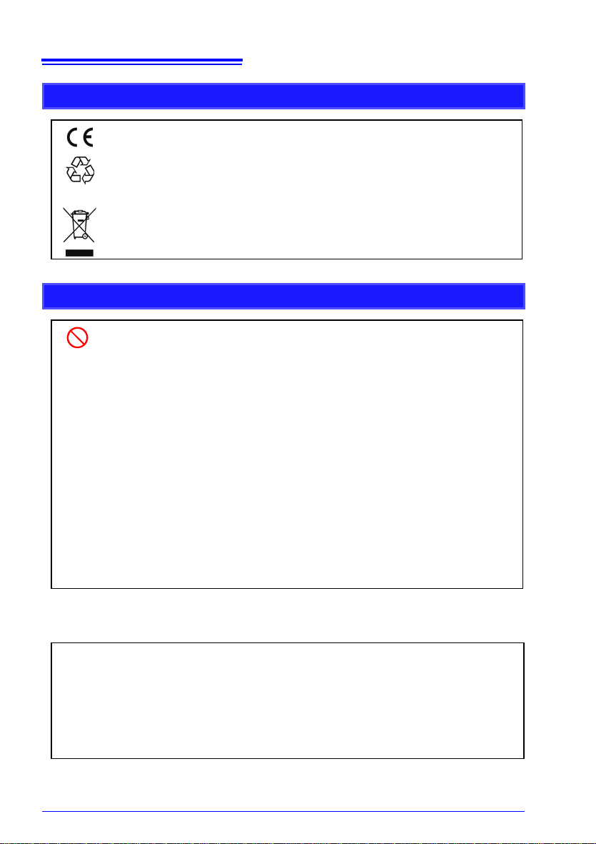
Symbols for Various Standards
This symbol indicates that the product conforms to re gulations set out by the EC
Directive.
This is a recycle mark established under the Res ource
(only for Japan).
WEEE marking:
This symbol indicates that the electrical and electroni c appliance is put on the EU
market af
display it on the appliance under Article 11.2 of Directive 2002/96/EC (WEEE).
ter August 13, 2005, and producers of the Member States are required to
Recycling Promotion Law
Other Symbols
Indicates the prohibited action.
(p. )
[ ]
SET
(Bold
charac-
ters)
• Unless otherwise specified, “Windows” represents Windows 2000, Windows XP, Windows
V
• Dialog box represents a Windows dialog box.
• Click: Press and quickly rel
• Double click: Quickly
Indicates the location of reference information.
Indicates that descriptive information is provided below.
*
The names of setting objects and buttons on the screen are i ndicated by square
brackets [ ].
Bold characters within the text indicate operating key labels.
ista, or Windows 7.
ease the left button of the mouse.
click the left button of the mouse twice.
Accuracy
We define measurement tolerances in terms of f.s. (full scale), rdg. (reading) and dgt.
(digit) values, with the following meanings:
f.s.
(maximum display value or
scale length)
rdg.
(reading or displayed value)
dgt.
(resolution)
The maximum displayable value or scale length. This is usually the
name of the currently selected range. Example: For the 1 V range,
f.s. = 1 V
The value currently being measured and indicated on the measuring instrument.
The smallest displayable unit on a digital measuring instrument,
i.e., the input value that causes the digital display to show a " 1" as
the least-significant digit.
Safety Information
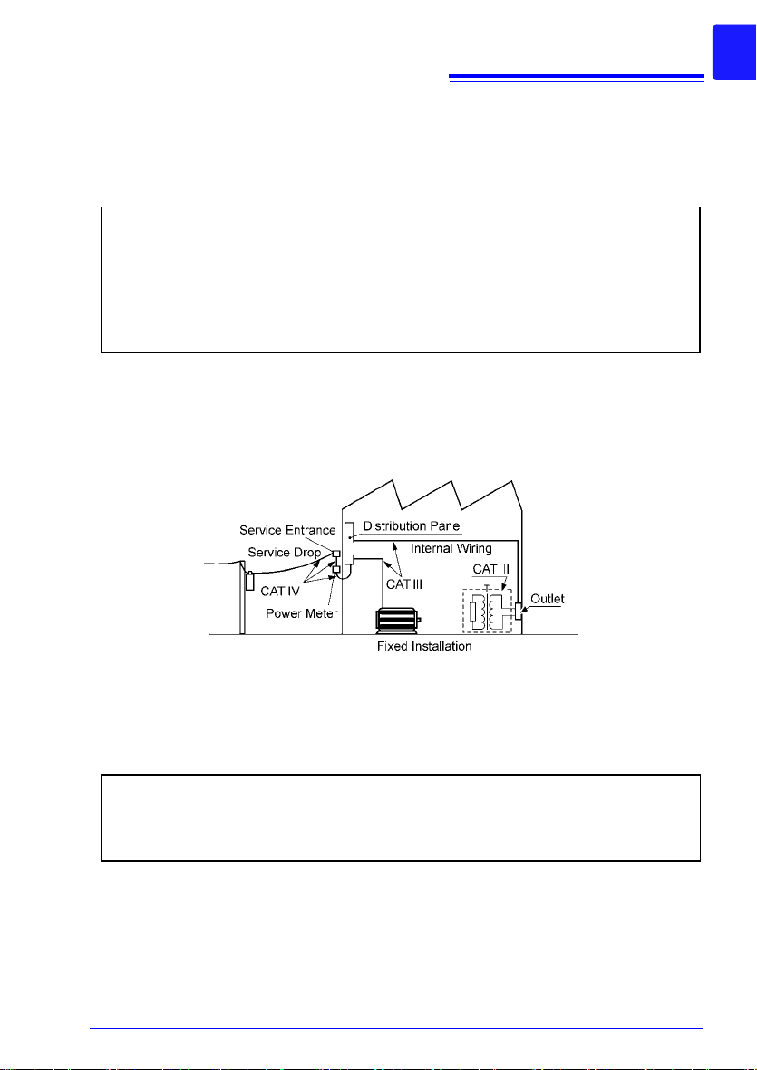
Measurement categories
This HiLogger complies with CAT II (300 VAC, DC) safety requirements.
To ensure safe operation of measurement instruments, IEC 61010 establishes safety
standards for various electrical environments, categorized as CAT II to CAT IV, and called
measurement categories.
5
CAT II:
CAT III:
CAT IV:
Primary electrical circuits in equipment connected to an AC electrical outl et by a
power cord (portable tools, household appliances, etc.)
CAT II covers directly measuring electrical outlet receptacles.
Primary electrical circuits of heavy equipment (fixed installations) connected
directly to the distribution panel, and feeders from the distribution panel to outlets.
The circuit from the service drop to the service entrance, and to the power meter
and primary overcurrent protection device (distribution panel).
Using a measurement instrument in an environment designated with a higher-numbered
category than that for which the instrument is rated could result in a severe accident, and
must be carefully avoided.
Use of a measurement instrument that is not CAT-rated in CAT II to CAT IV measurement
applications could result in a severe accident, and must be carefully avoided.
Difference between "Measurement" and "Recording"
The measurement and recording processes are distinguished as follows for the purposes
of these instructions.
Measurement: The acquisition of in put values into internal Hi Logger memory or to a PC via
Recording : Storing measurement data on a CF card, USB flash drive or on a PC via data
communications.
communication.
Measured data (data acquired in internal memory) is erased whenever a new measurement starts. To retain data, always record (save) it.
6
Operating Precautions
Operating Precautions
Follow these precautions to ensure safe operation and to obtain the full benefits of
the various functions.
Before Use
• Before using the HiLogger the first time, verify that it operates normally
ensure that no damage occurred during storage or shipping. If you
to
find any damage, contact your dealer or Hioki representative.
• Before using the HiLogger, make sure that the insulation on the cables
is undamaged and that no bare conductors are improperly exposed.
Using the HiLogger in such conditions could cause an electric shock, so
contact your dealer or Hioki representative for replacements.
Instrument Installation
Operating temperature and humidity: 0 to 40°C at 80% RH or less (non-
condensating)
Temperature and humidity range for guaranteed accuracy: 23±5°C,
80%RH or less
Avoid the following locations that could cause an accident or
damage to the instrument.
Exposed to direct sunlight
Exposed to high temperature
In the presence of corrosive or explosive gases
Installation Precautions
• Avoid temperature changes around the terminal block. Especially avoid
directed airflow such as from an electric fan or air conditioner vent.Ther
mocouple inputs are prone to measurement errors.
• When the HiLogger is moved to a location with significantly different
amb
ient temperature, allow at least 60 minutes for thermal equalization
before measuring.
Exposed to water, oil, other
c
hemicals, or solvents
Exposed to high humidity
r condensation
o
Exposed to high levels of
pa
rticulate dust
Exposed to strong electromagnetic fields
Near electromagnetic radiators
Subject to vibration
Near induction heating
sy
stems
(e.g., high-frequency induction heating systems
nd IH cooking utensils)
a
-
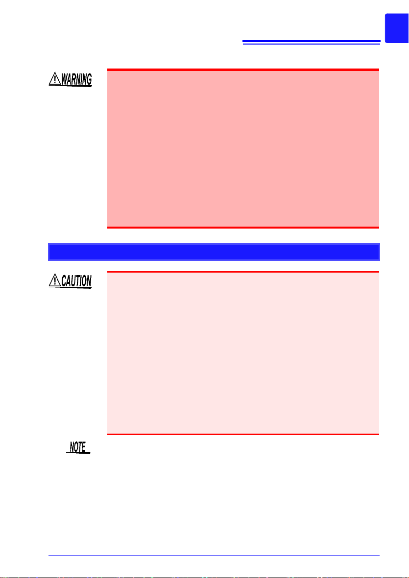
Handling the Instrument
To avoid electric shock, do not remove the HiLogger's case. The
internal components of the HiLogger carry high voltages and may
become very hot during operation.
Touching any of the high-voltage points inside the HiLogger is very
dangerous.
Do not attempt to modify , disass emble or rep
electric shock and injury could result.
To avoid damage to the HiLogger, protect it from physical shock when
transporting and handling. Be especially careful to avoid physical shock
from dropping.
This instrument may cause interference if used in residential areas. Such
use must be avoided unless the user takes special measures to reduce
electromagnetic emissions to prevent interference to the reception of radio
and television broadcasts..
Handling the Cords and Cables
• Avoid stepping on or pinching cables, which could damage the cable
insulation.
• To avoid breaking the cables, do not bend or pull them.
• To avoid damaging the power cord, grasp the plug, not the cord, when
ging it from the power outlet.
unplug
7
Operating Precautions
air the HiLogger; as fire,
Before Turning Power On
Before turning the HiLogger on, make sure the supply voltage
matches that indicated on the AC adapter. Connection to an im proper
supply voltage may damage the HiLogger or AC adapter and present
an electrical hazard.
When the power is turned off, do not apply voltage or current to the HiLogger. Doing so may damage the HiLogger.
• After use, always turn OFF the power.
• Brief power interruptions of 40 ms or less will not cause this HiLogger to
malfunction. However, Longer interruptions may cause the HiLogger to
shut itself off, so consider local power conditions before installing, as
appropriate.
• To ensure that recording is not interrupted by power outages, you can
e 9418-15 AC Adapter and Z1000 Battery Pack together.
use th

8
Operating Precautions
Using the Battery Pack
Be sure to observe the following precautions. Incorrect handling may
result in liquid leaks, heat generation, ignition, bursting and other
hazards.
• Use only the Hioki Model Z1000 Bat
responsibility for accidents or damage related to the use of any
other batteries.
See: "2.2 Using the Battery Pack (Option)" (p. 30)
• To avoid the possibility of explosion, do not short circuit, disassemble or incinerate battery pack.When storing the HiLogger, make
sure no objects that could short-circuit the connectors are placed
near them.
• The battery pack contains lye, which can cause blindness if comes
into contact with the eyes. Should battery liquid get into your eyes,
do not rub your eyes but rinse them in plenty of water and seek the
immediate attention of a physician.
• To avoid electric shock, turn off the power switch and disconnect
the cables before replacing the battery pack.
• After installing or replacing the battery pack, replace the battery
compartment cover and screw.
• Handle and dispose of batteries in accordance with local regulations.
tery Pack. We cannot accept
Observe the following to avoid damage to the HiLogger.
• Use the battery pack in an ambient temperature range of 0 to 40°C and
arge it in an ambient temperature range of 10 - 40°C.
ch
• If the battery packs fails to complete charging within the stipulated time,
isconnect the AC adapter from the pack to stop charging.
d
• Consult your dealer or nearest service station should liquid leaks,
strange odor, heat, discoloration, deformation and other abnormal conditions occur during use, charging or storage. Should these conditions
o
ccur during use or charging, turn off and disconnect the HiLogger
immediately.
• Do not expose the HiLogger to water and do not use it in excessively
h
umid locations or locations exposed to rain.
• Do not expose the HiLogger to strong impacts and do not throw it
a
round.

• The battery pack is subject to self-discharge. Be sure to charge the battery pack before initial use.
• The battery pack is a consumable. If the battery capacity remains very
low af
ter correct recharging, the useful battery life is at an end.
• Battery pack lifetime (to at least 60% initial full-charge capacity) is about
300
charge/discharge cycles.
• To prevent battery pack deterioration when the battery will not be used
for
1 month or longer, remove it and store it in a dry location with an
ambient temperature range of between -20 to 30°C. Be sure to discharge
and charge it every two months. Long-term storage at low battery capacity will reduce performance.
• During battery operation, the HiLogger automatically turns off when battery charge is depleted. Leaving the HiLogger in this state for a long time
ma
y cause over-discharge, so be sure to turn the HiLogger's power
switch off.
• When the HiLogger has turned off automatically due to low battery
charge, turn the power switch off and connect the AC adapter (or install
new batteries), then allow about 30 seconds before switching back on. If
the HiLogger is turned on too soon, it may turn off again automatically.
Using the AC Adapter
• Use only the supplied Model 9418-15 AC Adapter. AC adapter input
voltage range is 100 to 240 VAC (with ±10% stability) at 50/60 Hz. To
avoid electrical hazards and damage to the HiLogger, do not apply
voltage outside of this range.
• Turn the HiLogger off before connecting the AC adapter to the
HiLogger and to AC power.
• To avoid electrical accidents and to maint
tions of this HiLogger, connect the supplied power cord only to a 3contact (two-conductor + ground) outlet.
9
Operating Precautions
ain the safety specifica-

10
Operating Precautions
Connection Precautions
Connecting to the Analog Input Terminals
Do not leave the HiLogger connected to test objects in environments
where a voltage surge might exceed the dielectric withstand voltage.
Doing so could result in damage to the HiLogger, bodily injury or
fatal accident.
• This instrument is not drip-proof. To prevent liquid including water
from entering the instrument, in particular, drop measurement
cables down below the instrument.
• To avoid shock and short circuits, turn off the power to lines to be
measured before making connections to terminals to be measured
and turning on the HiLogger.
• To avoid shock and short circuits, turn off all power before connecting measurement cables.
• Do not connect a cable to the HiLogger while it is connected to the
obj
ect to be measured. Otherwise, an electric shock accident may
occur.
• To avoid short-circuit accidents, make
secure.
• To avoid electric shock and short-circuit accidents, always close
t
he analog input terminal cover and tighten the screws.
• To avoid electric shock, use the recommended wire type to connect
to the current input terminals, or otherwise ensure that the wire
used has sufficient current handling capacity and insulation.
• Channels are insulated by semiconduc
beyond the specification is applied between the channels, the semiconductor relay may short circuit. Please
beyond specification, especially a surge such as a lightning, is
never applied. When an abnormal measurement value is observed,
please contact your dealer or Hioki representative for inspection.
certain that connections are
tor relays. When a voltage
ensure that a voltage
• Measurements may be affected by noise or other electromagnetic
ingress if input leads are longer than about three meters.
• Route measurement leads and cables as far away as possible from
power and earth lines.
• Measurement values may be scattered if the leads are routed in parallel
with other devices. If they must be parallel, check operation before taking
measurements.
11
Operating Precautions
Connecting to the Pulse Input, Alarm Output, and Other External Control Terminals
• The External Control Terminals is not isolated from the HiLogger’s
chassis ground. Make certain that there will be no potential difference between the External Control Terminals and the ground of any
connected device. Otherwise, the HiLogger or device could be damaged.
• To avoid electric shock or damage to the equipment, always
observe the following precautions when connecting to pulse input
terminals, alarm output terminals, and External Control Terminals.
• Always turn off the power to the HiLogger and to any devices to be
connected before making connections.
• Be careful to avoid exceeding the ratings of External Control Terminals.
• Ensure that devices and systems to be connected to the External
Control Terminals are properly isolated.
Using a CF Card/USB flash drive
• Inserting a CF card/USB flash drive upside down, backwards or in the wrong
direction may damage the CF card, USB flash drive, or HiLogger.
• Never eject a CF card /USB flash drive while measuring or when the
HiLogge
may be destroyed. (The CF icon/USB flash drive icon at the lower left is
red while the card is being accessed.)
• Do not transport the HiLogger while a USB flash drive is connected.
D
• As the CF card/USB flash drive is sensitive to static electricity, damage to
the CF card/USB flash dr
occur due to static electricity. Please be careful when handling it.
• With some USB flash drives, the HiLogger may not start up if power is
turn
power on first, and then insert the USB flash drive. It is recommended to
try out operation with a USB flash drive before starting to use it for actual
measurements.
r is or accessing the card. Data on the CF card/USB flash drive
amage could result.
ive or wrong operations by the HiLogger may
ed on while the USB flash drive is inserted. In such a case, turn
• The Flash memory in a CF card/USB flash drive has a limited operating
life. After long-term usage, data storage and retrieval become difficult. In
this case, replace the CF card/USB flash drive with a new one.
• We cannot provide compensation for data loss in a CF card/USB flash
drive, regardless of content or cause of the damage. Data is also cleared
from memory if a long time passes after measuring. Always maintain a
backup of important data stored on a CF card/USB flash drive.
• Although real-time saving to USB flash drive is supported, a CF card is
reco
mmended for data preservation. Performance can not b e gu aran teed
when using storage media other than a Hioki-specified CF card option.

12
Operating Precautions
CD Handling
• Always hold the disc by the edges, so as not to make fingerprints on the
disc or scratch the printing.
• Never touch the recorded side of the disc. Do not place the disc directly
on anything hard.
• Do not wet the disc with volatile alcohol or water, as there is a possibility
of the label printing disappearing.
• To write on the disc label surface, use a spirit-based felt pen. Do not use
a ball-point pen or hard-tipped pen, because there is a danger of scratching the surface and corrupting the data. Do not use adhesive labels.
• Do not expose the disc directly to the sun's rays, or keep it in conditions
o
f high temperature or humidity, as there is a danger of warping, with
consequent loss of data.
• To remove dirt, dust, or fingerprints from the disc, wipe with a dry cloth,
o
r use a CD cleaner. Always wipe from the inside to the outside, and do
no wipe with circular movements. Never use abrasives or solvent cleaners.
• Hioki shall not be held liable for any problems with a PC system that
a
rises from the use of this CD, or for any problem related to the purchase
of a Hioki product.
13
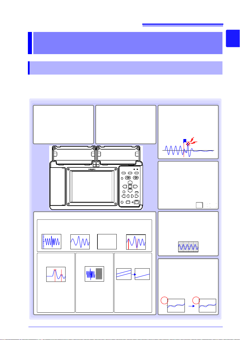
Record anomalies
Abnormal events can be analyzed by recording with the trigger function (p. 99).
Use the alarm function to output
signals when anomalies occur
(p. 109).
Waveform observation
A
B
123.4V
Acquire pulse signals
Measure integrated pulses or
revolutions from sensors and
pulse output devices such as
watt-hour meters.
Gauge
display (p. 86)
Zoom in/
out (p. 89)
Numerical
display (p. 87)
Event search
(p. 93)
T
1 2
Cursor Measurements (p. 91)
Using the A/B cursors, values at cursor
locations on waveforms and the time at
trigger positions can
be displayed.
Simultaneously performs six numerical
calculation types, including maximum
and average values.
Numerical Calculations (p. 143)
Waveform Calculations (p. 149)
Displays on one
channel the sum, difference, product, or
quotient of values
measured on any two
analog channels.
CH1-1
CH2-1
W1
Measurement data and
setting configurations
are stored, read and
managed as data files
Measurement data can be
stored to and read from an optional CF card or USB flash
drive (p. 121).
Observe on a PC
Monitor and analyze measurement data with the supplied application program "Logger
Utility" (p. 187).
Display in converted
units
Using the scaling function, input
values can be displayed in units
of the actual physical quantity
being measured, such as current or flow volume (p. 69).
mV A
Voltage change, temperature, humidity, and
resistance observation
Just connect measurement
leads or thermocouples to measure as needed.
1.1 Product Overview and Features
Overview Chapter 1
1.1 Product Overview and Features
The portable data logger is expandable from 30 to 60 channels. Data variations can
be observed on the high-resolution color LCD screen, and monitored on a PC connected via LAN or USB.
1
Chapter 1 Overview
3
14
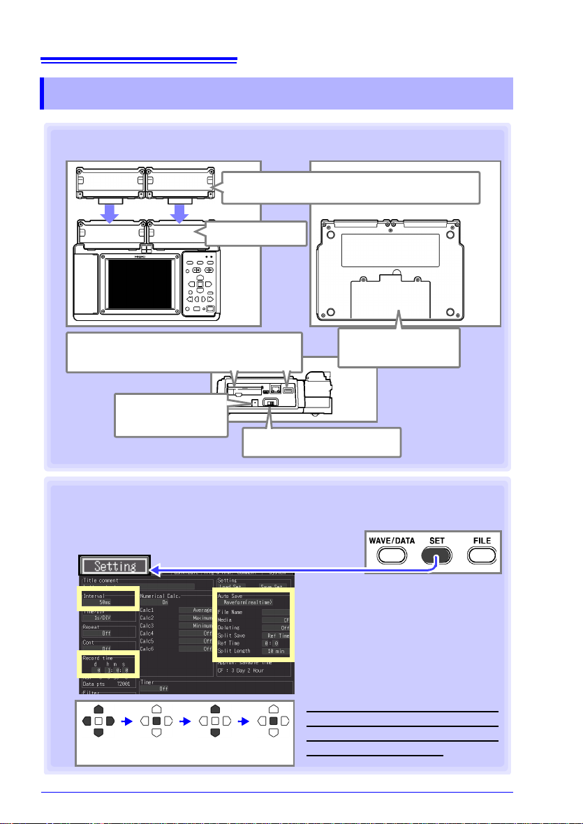
To save data,
insert a CF card/USB flash drive.
3. AC adapter
connection
5.Turn the Power On
Front
Panel
Rear
Panel
Right
Side
1. Preparations for Measurement (p. 27)
1. Attach Expan sion Unit s (as needed)
2. Install the
Battery Pack
4. Connecting
Configure Recording Settings (p. 50)
1 Set the data acquisition (record-
ing) interval, and recording length
(time spa
n).
2 Enable auto saving of measured
data to removable storage (CF
card or USB flash drive) (p. 125).
Data stored in internal memory is lost
about 30 minutes after power-off. We
recommend auto saving important
data to removable storage.
Move to a
setting item
Open the
setting options
Select Apply
1
1
2
2. Settings (p. 49)
1.2 Measurement Flow
1.2 Measurement Flow
15
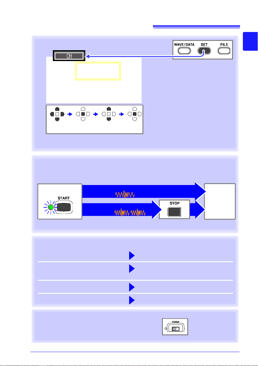
Select input channels, and set input
types and measurement ranges.
Pre-existing setting configuration data can be loaded from the HiLogger or removable storage (p. 132).
Make other settings as needed.
Waveform Display (p. 65)
Scaling (p. 69)
Titles and Comments (p. 71)
Noise Suppression (p. 73)
View/Edit All-Channel Settings List
(p. 74)
Move to a
setting
Open the
setting
Select Apply
Configure Input Channels (p. 53)
Press the START / STOP
Measure (Record) once, and stop.
[Repeat]: Off
Stop
Measure-
ment
When measuring (recording) using the trigger function (p. 99), measuring occurs only
when an input waveform satisfies the specified trigger criteria.
(default setting)
Measure (Record) repeatedly.
[Repeat]: On
3. Starting and Stopping Measurement (p. 23)
Start Measurement
4. Observing Data
View Measurement Data (p. 83)
Waveforms can be zoomed and numerical values confirmed.
Save Data (p. 121)
Measurement data, waveform data,
screen images and numerical calculation results can be saved.
Calculate (p. 143)
Numerical measurement data can be applied to calculations.
View on a PC (p. 187)
Observe measurement data with the
supplied Logger Utility program.
5. When Finished
Turn the HiLogger Off (p. 44)
1.2 Measurement Flow
1
Chapter 1 Overview
3
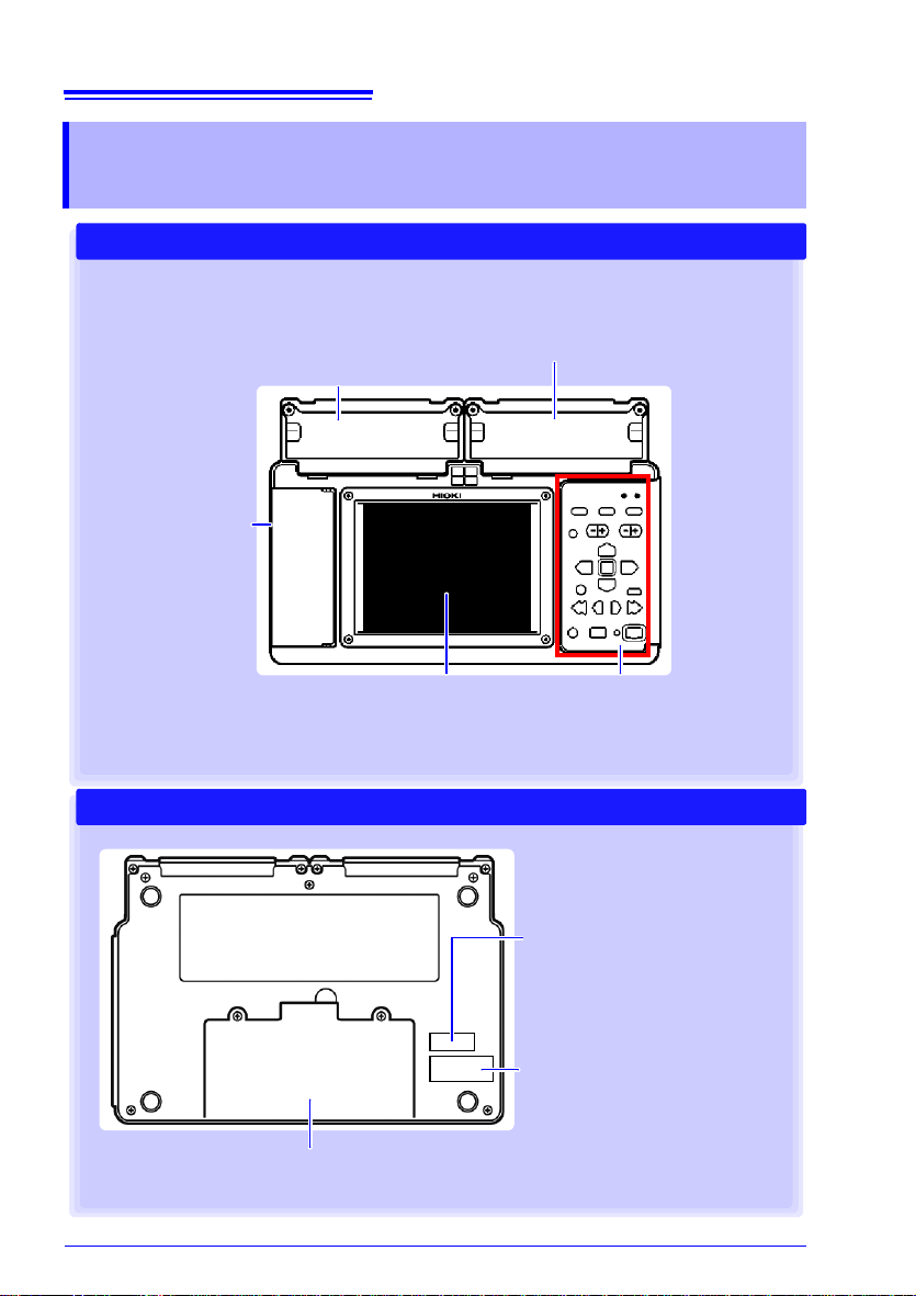
16
Universal Unit
Use to measure voltage, thermocouple temperature, humidity (with the Hioki Z2000 Humidity
Sensor), resistance, and temperature with resistance temperature detectors (RTDs) (p. 33).
Input units are installed as
specified upon factory
shipping.
Front Panel
Display Screen (p. 85)
5.7-inch TFT color LCD
Screen Configurations (p. 19)
Operating Keys/LED
(p. 17)
Voltage/Temp Unit
Use to measure voltage, thermocouple
temperature, and humidity (with the Hioki
Z2000 Humidity Sensor) (p. 33).
External Control
Terminals (p. 33)
• Pulse inputs
(8 channels)
• Alarm outputs
(4 channels)
• External control
(one each input, output, and ground channel)
• 12-volt output
• Four alarm channel
LEDs indicate alarm
events (p. 163)
Rear Panel
Battery Compartment (p. 30)
The optional Model Z1000 Battery Pack is installed here.
Serial No.
Shows the serial number.
Do not remove this label, as it is
required for product support.
MAC address
Shows the MAC address.
Do not remove this label, as it is
required for product support.
1.3 Names and Functions of Parts, Screen Configurations
1.3 Names and Functions of Parts, Screen
Configurations
17
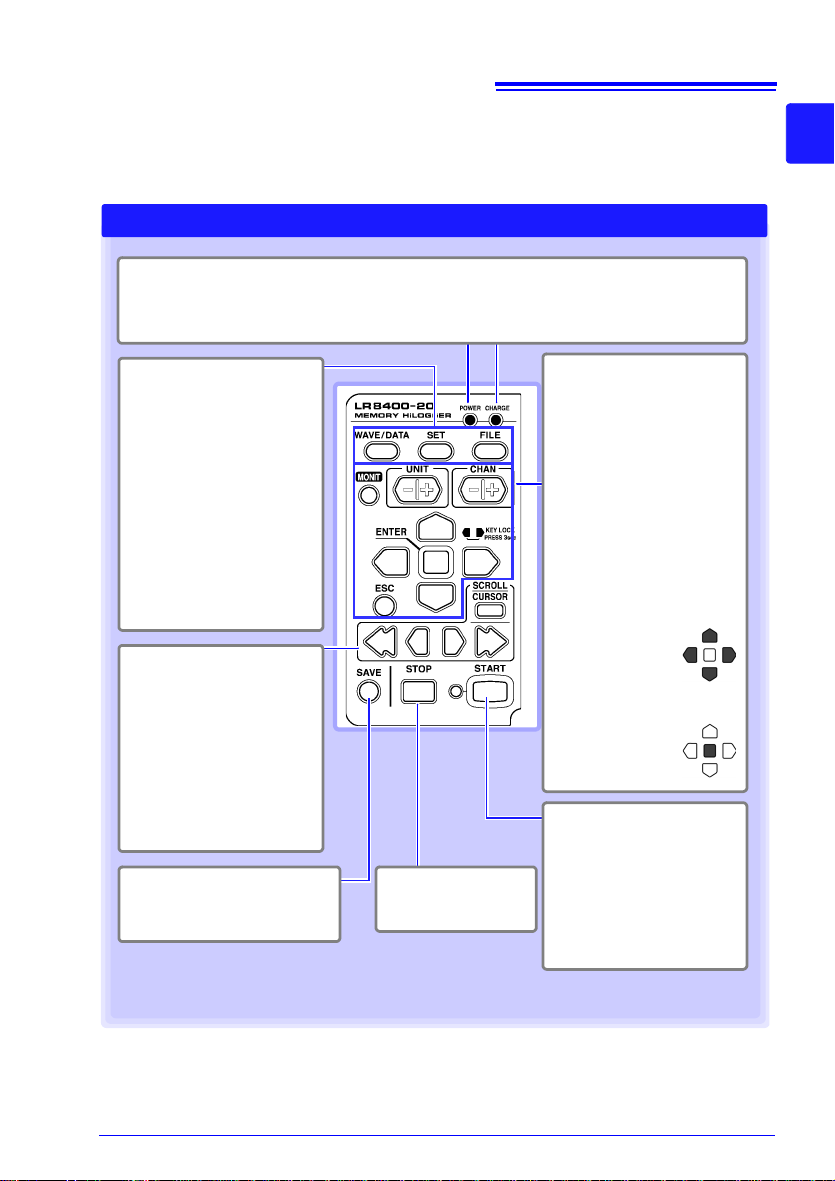
Operating Keys/LED
WAVE/DATA
Selects among Waveform/
Numerical
screen displays
(p. 19).
SET
Displays the Settings screens,
and switches among the
screen tabs with each press (p.
21).
FILE
Displays file information
(p. 20).
Choose a screen
Press to save data manually
(p. 124)
.
Saving operations
Setup and display
HiLogger Status Indicators
POWER
Lights when powered on (p. 44).
CHARGE
Lights while charging the Z1000 Battery Pack
(p. 31).
SCROLL/CURSOR
Select waveform scrolling or
A/B cursor movement.
Left and Right
Cursor keys
Scroll waveforms and move
A/B cursors (p. 22).
Scroll waveforms and
read cursor values
Stop
measurement
Start and stop measurement.
The LED at the left lights
green while measuring
(p. 23)
.
Press while measuring to insert event markers in the measurement data. (p. 93)
Start measurement
CHAN
Select channels.
UNIT
Switches input units.
MONIT
Shows the current input
waveform and numerical values (data not stored in internal memory).
ESC
Cancels changes to settings.
Cursor keys
Moves the position
of the cursor (blinking selection) on
the screen.
ENTER
Accepts displayed
settings.
1.3 Names and Functions of Parts, Screen Configurations
1
Chapter 1 Overview
3
18
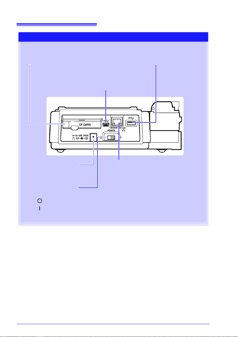
Right Side
POWER Switch
Turns the HiLogger on and off (p. 44).
Power Off
Power On
Ethernet Jack (RJ-45)
Use for PC communications via LAN.
Connect an optional Model 9642 LAN Cable (p.
184).
AC Adapter Socket
Connect the supplied Model
9418-15 AC Adapter (p. 32).
CF Card Slot
Use to save data to a CF card.
Insert an optional CF card (p. 46).
USB Port
Use to save data to a USB flash drive.
Insert an USB flash drive (p. 46).
USB Cable Port (USB 2.0 mini-B receptacle)
Use for PC communications via USB. Connect th e supplied USB cable (p. 170).
1.3 Names and Functions of Parts, Screen Configurations
 Loading...