

Hioki LR5051 Instruction Manual

Instruction Manual
LR5051
CLAMP LOGGER
July 2013 Revised edition 2 LR5051B980-02 13-07H


Contents
Introduction ..............................................................................1
Verifying Package Contents....................................................3
Safety Information....................................................................5
Operating Precautions.............................................................6
Measurement Preparation to Data Analysis ..........................8
i
Contents
1
2
3
Chapter 1
Overview__________________________________13
1.1 Product Overview and Features .............................13
1.2 Part Names/Functions and Display Indicators .....14
1.3 Display Organization ...............................................16
Chapter 2
Measurement Preparations___________________ 19
2.1 Installing (or Replacing) the Battery ......................19
2.2 Connecting a Clamp Sensor ...................................22
2.3 Installing the PC Application Program ..................29
Chapter 3
Settings___________________________________35
3.1 Settings List .............................................................35
3.2 Making Settings on the Logger ..............................37
3.3 Making Settings from the LR5000 Utility Program 43
Chapter 4
Measurement and Analysis___________________ 51
4.1 Pre-Measurement Inspection .................................51
4.2 Installing the Logger ...............................................52
4.3 Starting and Stopping Recording ..................... ... ..53
4.4 Confirming Currently Measured Values and Data
Recording .......................... .......................... ............. 55
4.5 Automatically Importing (Saving) Recorded Data
to a Computer, and Graph Display ........................55
4

ii
Contents
4.6 Manually Importing (Saving) Recorded Data to a
Computer, and Graph Display ............................... 65
4.7 Displaying a Graph of Saved Recording Data ..... 68
4.8 Printing Recorded Data .......................................... 70
Chapter 5
Processing Recorded Data ___________________71
5.1 Scaling ..................................................................... 73
5.2 Calculating Electric Power ..................................... 74
5.3 Calculating Energy Cost ....... .. ... .. ... ... .. .................. 75
5.4 Calculating Operating Rate ............. ... .. ... .. ... .......... 76
5.5 Integration ............................................................... 77
5.6 Calculating Dew-Point Temperature ..................... 78
5.7 Two-Data-Item Arithmetic Calculations ................ 79
5.8 Converting Over-Threshold Data Values .............. 80
Chapter 6
Organizing Data ____________________________81
6.1 Copying and Moving Data ...................................... 82
6.2 Deleting Data .................. ......................................... 83
6.3 Combining Data ...................................................... 84
6.4 Extracting Data ....................................................... 85
Chapter 7
Options Settings (LR5000 Utility Program) ______87
7.1 Changing the Saving Method for Imported Data . 88
7.2 Changing the Connection Monitoring Method,
and Logger Settings Displays ............................... 89
Chapter 8
Specifications______________________________91
8.1 Measurement Specifications ................................. 91
8.2 Functional Specifications ...................................... 92
8.3 Miscellaneous ......................................................... 93
8.4 LR5091 Communication Adapter Specifications . 94

Chapter 9
Maintenance and Service ____________________97
9.1 Cleaning ...................................................................97
9.2 Disposing of the Logger .........................................97
9.3 Troubleshooting ......................................................98
9.4 Error Displays . .......................................................100
Appendix_________________________________ A 1
iii
Contents
Appendix 1 About Recording Modes.............................. A 1
Appendix 2 Recording Intervals and Maximum
Recording Times.......................................... A 2
Appendix 3 Battery Life Approximation...................... ... A 2
Appendix 4 Measurement Method .................................. A 3
Index _________________________________Index 1
4
5
6
7
8
9
Appendix
Index

iv
Contents
1
Introduction
Introduction
Thank you for purchasing the HIOKI "Model LR5051 Clamp Logger." To obtain maximum performance from the instrument, please read this manual first, and keep it
handy for future reference.
Registered Trade Marks
Windows is a registered trademark of Microsoft Corporation in the United States and/
ther countries.
or o
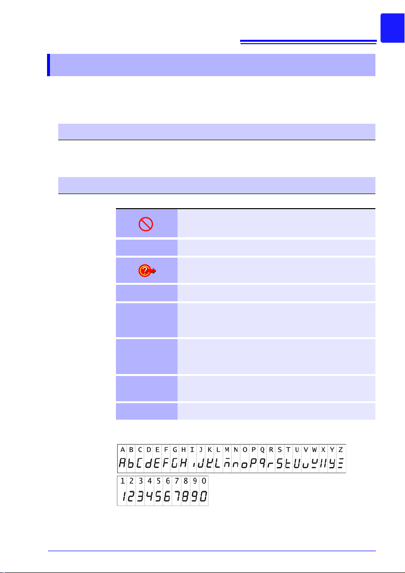
Notation
Indicates a prohibited action.
(p. ) Indicates the location of reference information.
Indicates quick references for operation and remedies for
troubleshooting.
* Indicates that descriptive information is provided below.
Menus, commands, dialogs, buttons in a dialog, a nd other
[ ]
SET
(Bold charac-
ters)
Windows
Dialog Dialog box represents a Windows dialog box.
The screen of this instrument displays characters in the following manner.
names on the screen and the buttons are indicated in
brackets.
Bold characters within the text indicate operating button
labels.
Unless otherwise specified, “Windows” represents Windows XP, Windows Vista, or Windows 7.

2
Introduction
Accuracy
We define measurement tolerances in terms of rdg. (reading) and dgt.
(digit) values, with the following meanings:
rdg.
(reading or displayed
value)
dgt.
(resolution)
The value currently being measured and indicated
on the measuring instrument.
The smallest displayable unit on a digi tal measuring instrument, i.e., the input value that causes the
digital display to show a "1" as the least-significant
digit.
Mouse Operation
Click Press and quickly release the left button of the mouse.
Right-click
Double click Quickly click the left button of the mouse twice.
Drag
Activate Click on a window on the screen to activate that window.
Press and quickly release the right button of the mouse.
While holding down the left button of the mouse, move the
use and then release the left button to deposit the cho -
mo
sen item in the desired position.
3
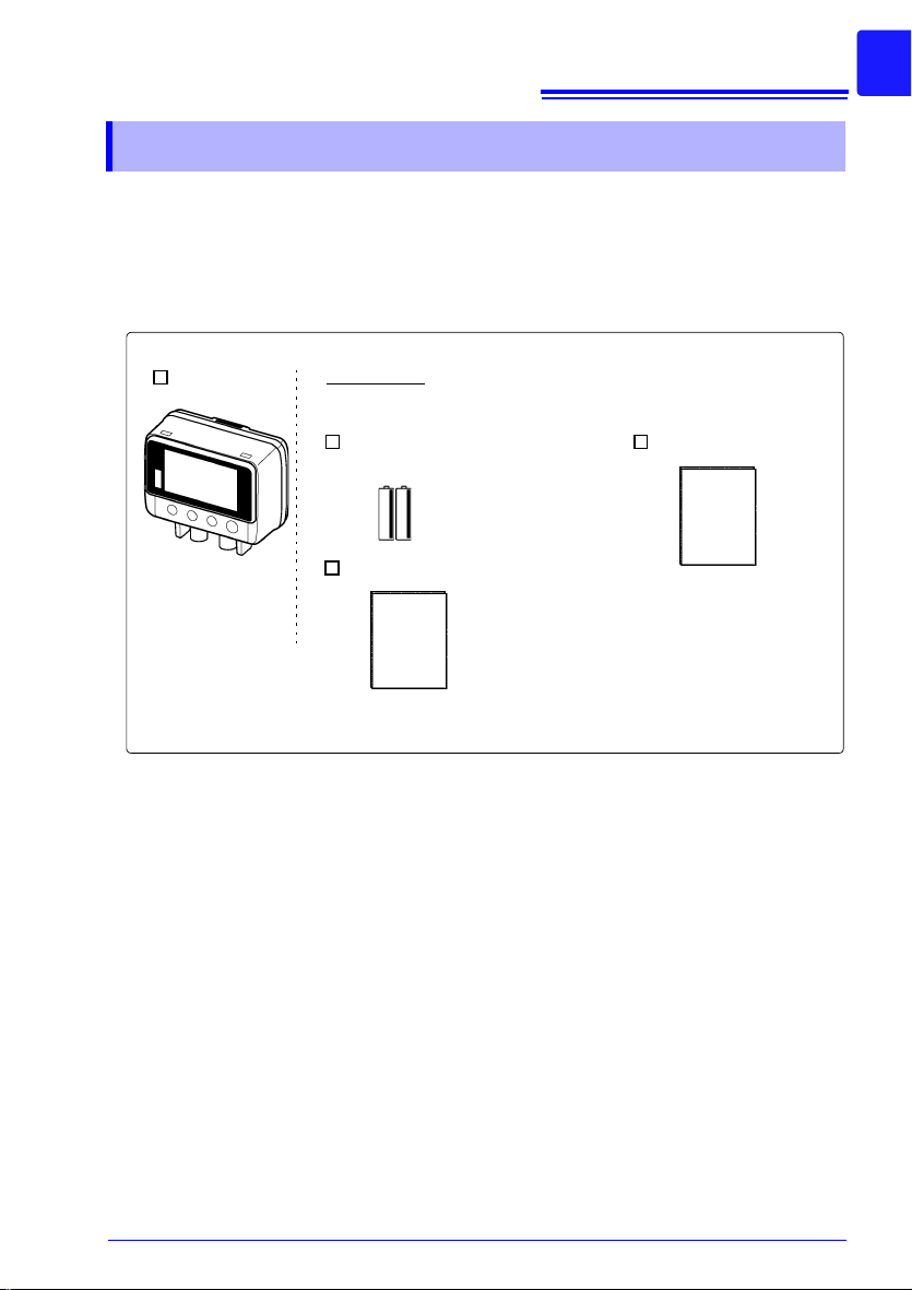
LR5051(1)
LR6 alkaline battery (2)
(Pre-installed in the logger.)
Accessories
See: Other specified option s: " O ptions" (p.4)
Instruction Manual (1)
Operation Manual (1)
Verifying Package Contents
Verifying Package Contents
When you receive the instrument, inspect it carefully to ensure that no damage
occurred during shipping. In particular, check the accessories, panel switches, and
connectors. If damage is evident, or if it fails to operate according to the specifications, contact your dealer or Hioki representative.
Quantities in parentheses ( ).
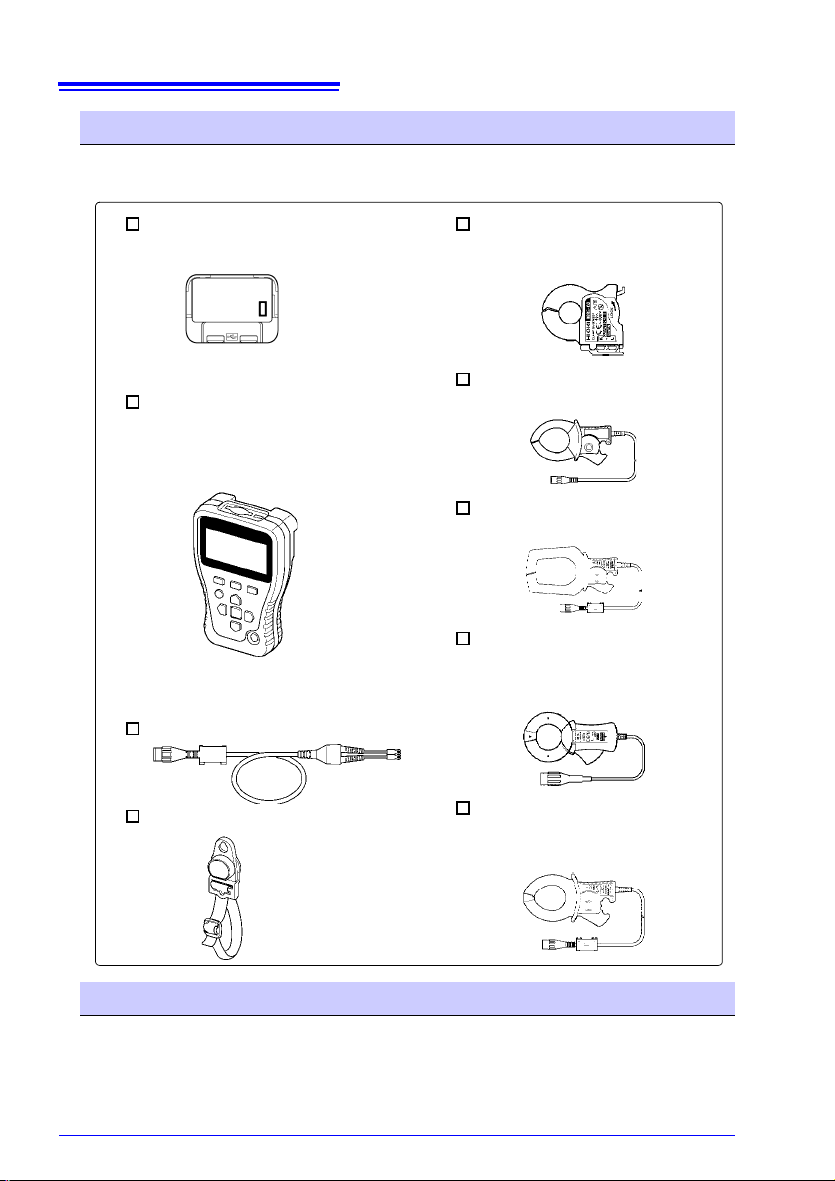
4
LR5092-20 Data Collector
(Includes LR5000 Utility Program* CD [PC application software], LR6 alkaline battery x2, I nstruction manual, Operation manual, and USB
Cable)
9695-02 Clamp On Sensor
50 A AC load current
Note: Requires 9219 Connection
Cable
LR5091 Communication Adapter(1)
(Includes LR5000 Utility Program* CD [PC application software] and USB Cable)
*:The latest version can be download-
ed from our web site.
CT6500 Clamp On Sensor
AC500 A AC load current
9669 Clamp On Sensor
1000 A AC load current
9675 Clamp On Leak Sensor
10A AC leakage current
Note: Displays up to 5.000 A with
the LR5051
See: LR5091 specification:(p.94)
Z5004 Magnetic Strap
9219 Connection Cable
9657-10 Clamp On Leak Sensor
10A AC leakage current
Note: Displays up to 5.000 A with
the LR5051
See: Method of mounting:
(p.52)
Verifying Package Contents
Options
The following logger options are available separately. Even if purchased previously,
you may want to confirm that you have them at hand.
Transporting Precautions
Use the original packing materials when transporting the instrument, if possible.
Pack the instrument so that it will not sustain damage during shipping, and include a
description of existing damage. We do not take any responsibility for damage incurred
during shipping.

5
Safety Information
Safety Information
This manual contains information and warnings essential for safe operation of the
instrument and for maintaining it in safe operating condition. Before using it, be
sure to carefully read the following safety precautions.
This instrument is designed to comply with IEC 61010 Safety Standards, and has been thoroughly te
ment. However, mishandling during use could re
death, as well a s damage to the instrument. However, using the
instrument in a way not described in this manual may negate the
provided safety features.
Be certain that you understand the instruc
the manual before use. We disclaim any responsibility for accidents or injuries not resulting directly from instrument defects.
Safety Symbols
Markings on the logger have the following meanings.
In the manual, the symbol indicates particularly important information that the user should read before using the instrument.
The symbol printed on the instrument
should refer to a corresponding topic in the manual (marked w ith the
symbol) before using the re
Indicates DC (Direct Current).
Symbols for Various Standards
Markings on the logger have the following meanings.
WEEE marking:
This symbol indicates that the electrica
put on the EU market after August 13, 2005, and producers of the
Member States are required to display it on the appliance under Article 11.2 of Directive 2002/96/EC (WEEE).
This symbol indicates that the product conforms to safety r egulations set out by the EC Directive.
sted for safety prior to ship-
sult i n injury or
tions and precautions in
indicates that the user
levant function.
l and electronic appliance is
Danger Levels
The following symbols in this manual indicate the relative importance of cautions and warnings.
Indicates that incorrect operation presents an extreme hazard
that could result in serious injury or death to the user.
Indicates that incorrect operation
that could result in serious injury or death to the user.
Indicates that incorrect operation presents a possibility of
in
jury to the user or damage to the instrument.
Indicates advisory items related to performance or correct
ope
ration of the
instrument.
presents a significant hazard
6
Operating Precautions
Operating Precautions
Follow these precautions to ensure safe operation and to obtain the full benefits of the various functions.
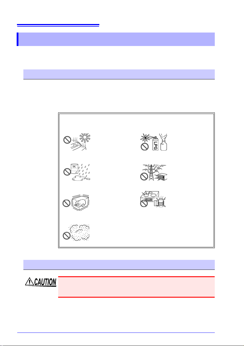
Installation Precautions
• Operating temperature and humidity: 0 to 50C (32 to 122F), 80%RH or less
• Storage temperature and humidity: -10 to 60C (14F to 140F),
80%RH or less (non-condensating)
• Operating environment: indoors
Avoid the following locations that could cause an accident or damage to the instrument.
Transporting and Handling
To avoid damage to the instrument and sensors, protect it from physical
shock when transporting and handling. Be especially careful to avoid
physical shock from dropping.
Exposed to direct
sunlight
Exposed to high temperature
Exposed to liquids
Exposed to high
y or condensa-
humidit
tion
Subject to vibration
Exposed to high levels of particulate dust
In the presence of
corrosive or explosive
gases
Exposed to strong
romagnetic
elect
fields
Near electromagnetic
radiators
Near induction heating systems
(e.g., high-frequency
ction heating sys-
indu
tems and IH cooking
ensils)
ut

CD Handling
7
Operating Precautions
• Always hold the disc by the edges, so as not to make fingerprints on
the disc or scratch the printing. Never touch the recorded side of the
disc. Do not place the disc directly on anything hard.
• Do not wet the disc with volatile alcohol or water, as there is a possibility of the label printing disappearing.
• To write on the disc label surface, use a spirit-based felt pen. Do not
u
se a ball-point pen or hard-tipped pen, because there is a danger of
scratching the surface and corrupting the data. Do not use adhesive
labels.
• Do not expose the disc directly to the sun's rays, or keep it in conditions of high temperature or humidity, as there is a danger of warping,
with
consequent loss of data.
• To remove dirt, dust, or fingerprints from the disc, wipe with a dry
cloth, or use a CD cleaner. Alway s wipe from the insid e to the o utside,
and do no wipe with circular movements. Never use abrasives or solvent cleaners.
• Hioki shall not be held liable for any problems with a computer system
th
at arises from the use of this CD, or for any problem related to the
purchase of a Hioki product.
Preliminary Checks
Before using the instrument the first time, verify that it operates normally to ensure
that the no damage occurred during storage or shipping. If you find any damage, contact your dealer or Hioki representative.
Before using the instrument, make sure that the insulation on the
sensor cables is undamaged and that no bare conductors are
improperly exposed. Using the instrument in such conditions
could cause an electric shock, so contact your dealer or Hioki representative for replacements.
8
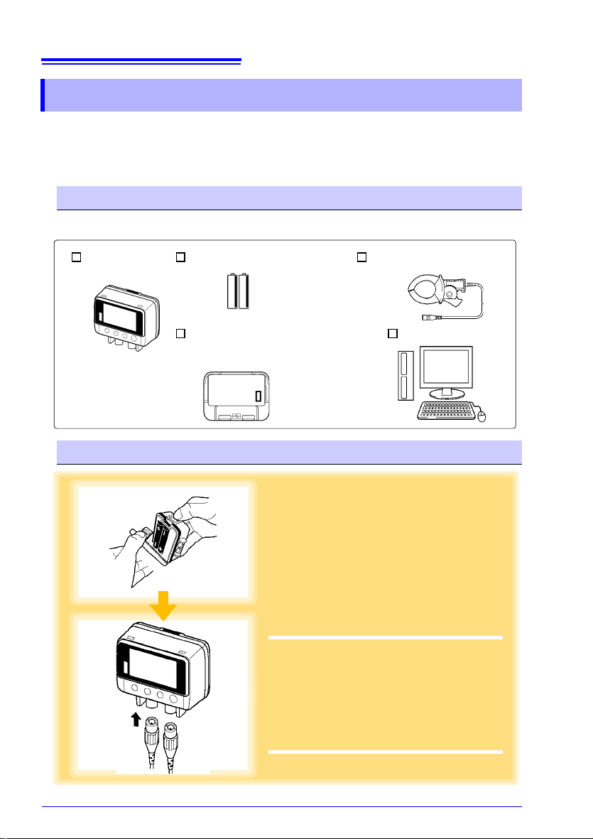
LR5051 (1) LR6 alkaline battery (2) CT6500 Clamp On Sensor (1)
LR5091 Communication Adapter (1)
(CD [PC application software] and
USB Cable)
Computer (1)
1
Install the battery in the logger.
See: "Installing (or Replacing) the Bat-
tery" (p.19)
2
Connect the CT6500 Clamp On Sensor to
the logger.
See: "Connecting a Clamp Sensor"
(p.22)
1
2
Measurement Preparation to Data Analysis
Measurement Preparation to Data Analysis
The steps from measurement preparation to data analysis are illustrated with a typical measurement example.
Example case: Record factory current consumption at one-minute intervals for one
month, and store the data on a computer.
Required Items:
Quantities in parentheses ( ).
Procedure:
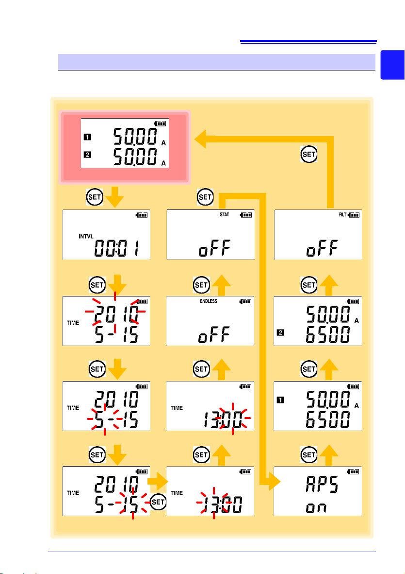
Measurement Preparation to Data Analysis
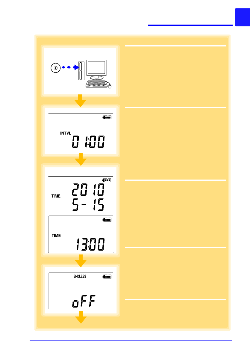
3
Install the LR5000 Utility Program on the
computer.
See: "Installing the PC Application Pro-
gram" (p.29)
4
Select the recording interval for the logger
(in this case, 1 minute).
See: "Recording In terval Setting" (p.37)
(The setting can be made also from the
LR5000 Utility Program.) (p.46)
5
Set the logger to the correct date and time
(in this case, 15 May 2010, 13:00).
See: "Real-Time Clock Setting" (p.38)
(With the LR5000 Utility Program, the logger can be set to the computer time.)
(p.49)
6
Set the stop method to [OFF].
(This setting provides one-time measurement:
recording stops when memory becomes full.)
See:
"Stop Method Setting (for when
memory becomes full)" (p.39)
(The setting can be made also from the
LR5000 Utility Program.) (p.46)
5
4
3
6
9
10
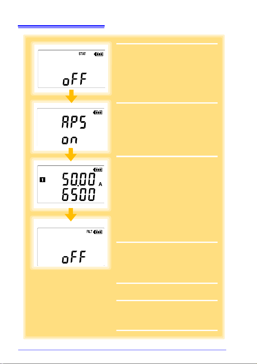
7
Set the recording mode to [OFF].
(This setting provides instantaneous measurement.)
See:
"Recording Mode Setting" (p.40)
(The setting can be made also from the
LR5000 Utility Program.) (p.46)
8
Set the power save setting to [ON].
(The on (enabled) setting is recommended
for long-term recording.)
See:
"Power Save Setting" (p.40)
(The setting can be made also from the
LR5000 Utility Program.) (p.45)
9
Set the CH1 measurement range to
[6500 50.00 A].
See: "Selecting the Clamp Sensor
Model and Measurement Range"
(p.41)
(The model name of the clamp sensor is
displayed above the current range.)
Note: The CT6500 Clamp On Sensor is
displayed as [6500] on the screen.
10
Set the filter to [OFF].
See: "Filter Setting" (p.42)
11
Pre-measurement inspection (p.51)
12
Install the logger at the measurement
site in the factory.
See: "4.2" (p.52)
It can be wall-mounted.)
8
9
7
10
Measurement Preparation to Data Analysis
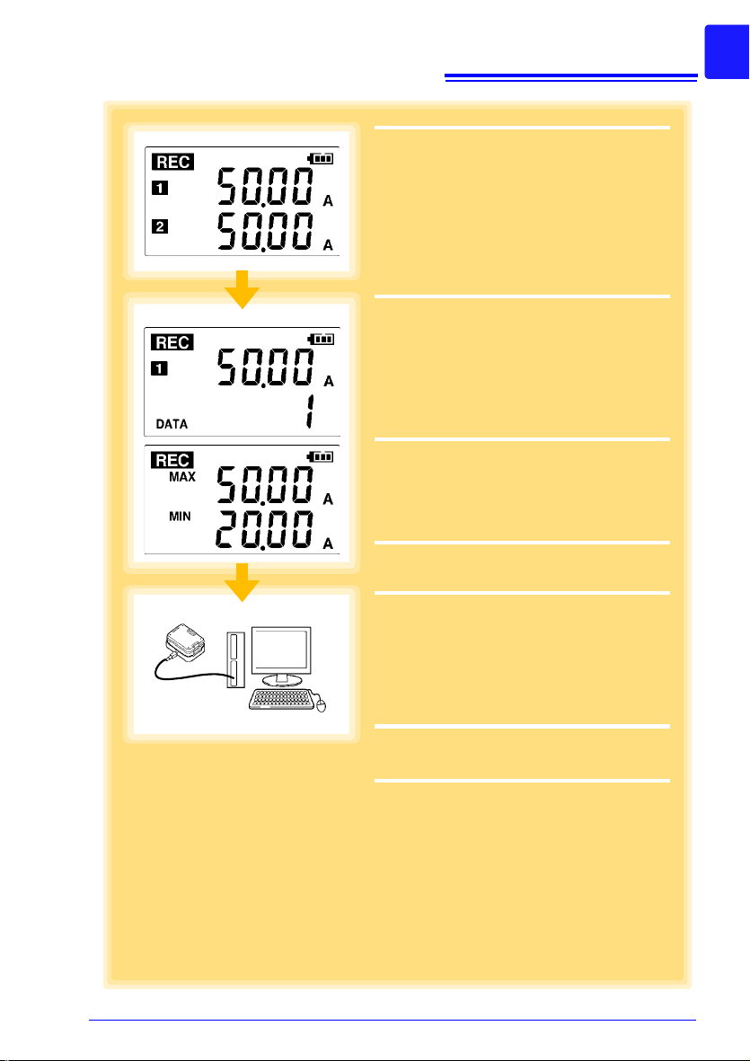
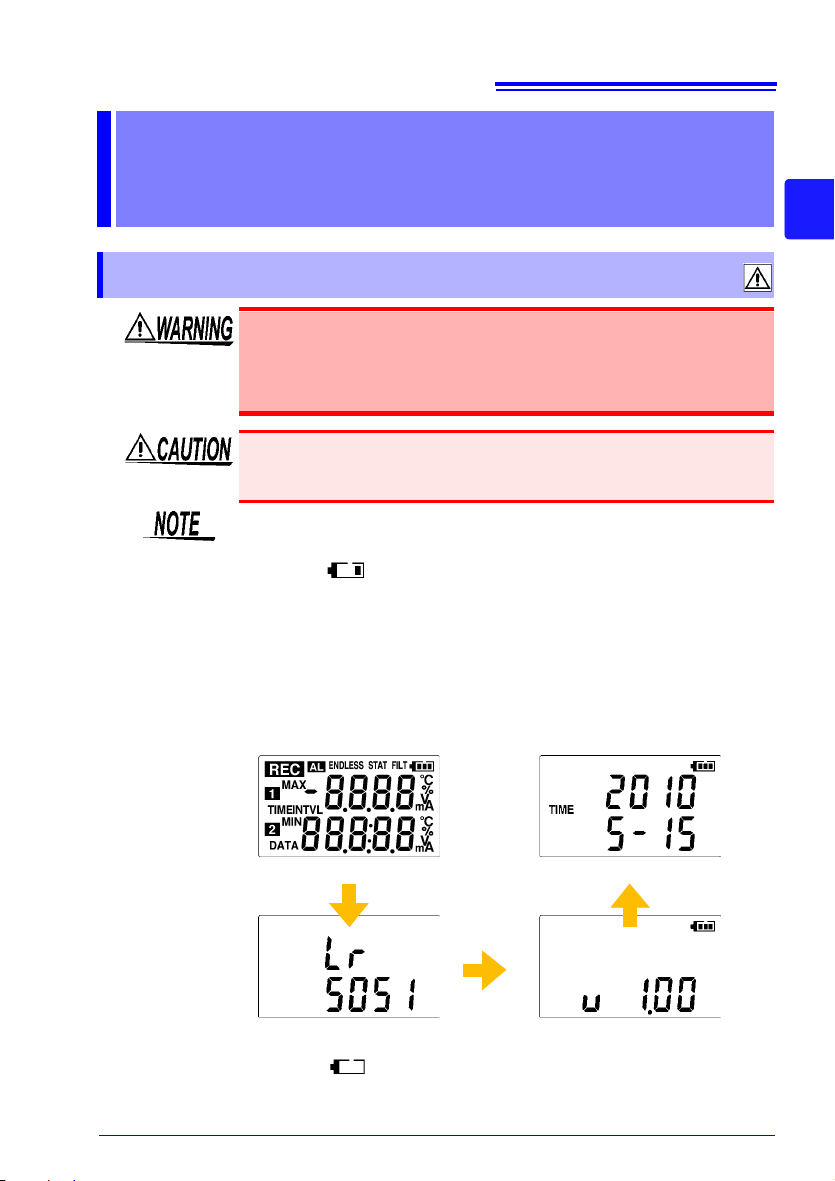
11
13
Hold REC/STOP on the logger for two
seconds to start recording.
See: "4.3" (p.53)
14
Press (+) and (-) on the logger to confirm
that the recording count is incrementing,
and that recording data (maximum and
minimum values) are displayed.
(Confirm that recording is actually occurring.)
See:
"4.4" (p.55)
15
After a month, hold REC/STOP on the
logger again for two seconds to stop
recording.
See: "4.3" (p.53)
16
Retrieve the logger from the factory.
17
Import recorded data from the logger to
a connected computer. For analysis, display the data in a graph.
See: "4.5" (p.55)
The data is automatically saved when
imported to the computer. By default, it is
also automatically displayed in a graph.)
18
Print recorded data as needed.
See: "4.8" (p.70)
13
17
14
Measurement Preparation to Data Analysis

12
Measurement Preparation to Data Analysis
13
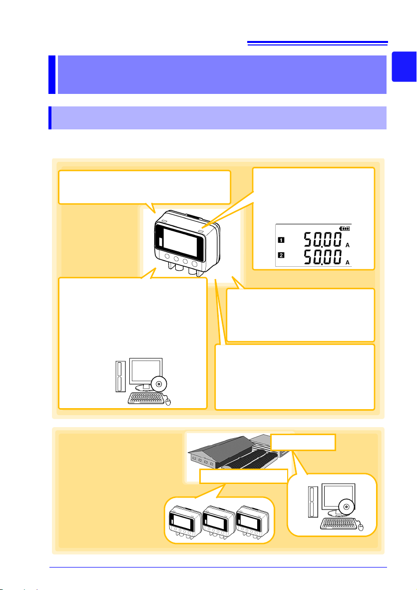
Browse and manage data with
LR5000 Utility Program on a PC.
The LR5000 Utility Program PC application is very easy to install.
After installation, data management and
browsing is easy with auto-start, data display and saving.
Large display shows two
channels' data simultaneously
Measures AC current on two
channels.
• Data can be imported while recording.
• Records up to 60,000 measurements
• Data is preserved independently
of battery state.
• Recording continues (for approx.
30 s) during battery replacement
Advanced functions included
• Record statistical values (p .3 9), (p.46)
• Scaling (p.47), (p.73)
• Alarm display (p.48)
Measurement Sites
Analysis Site
Energy saving measurements in
houses, offices, factories, warehouses, etc.
Suitable for ESCO environmental
measurements.
1.1 Product Overview and Features
Overview Chapter 1
1.1 Product Overview and Features
This instrument is a compact portable data logger for measuring, displaying, and
recording AC current.
1
Chapter 1 Overview
3
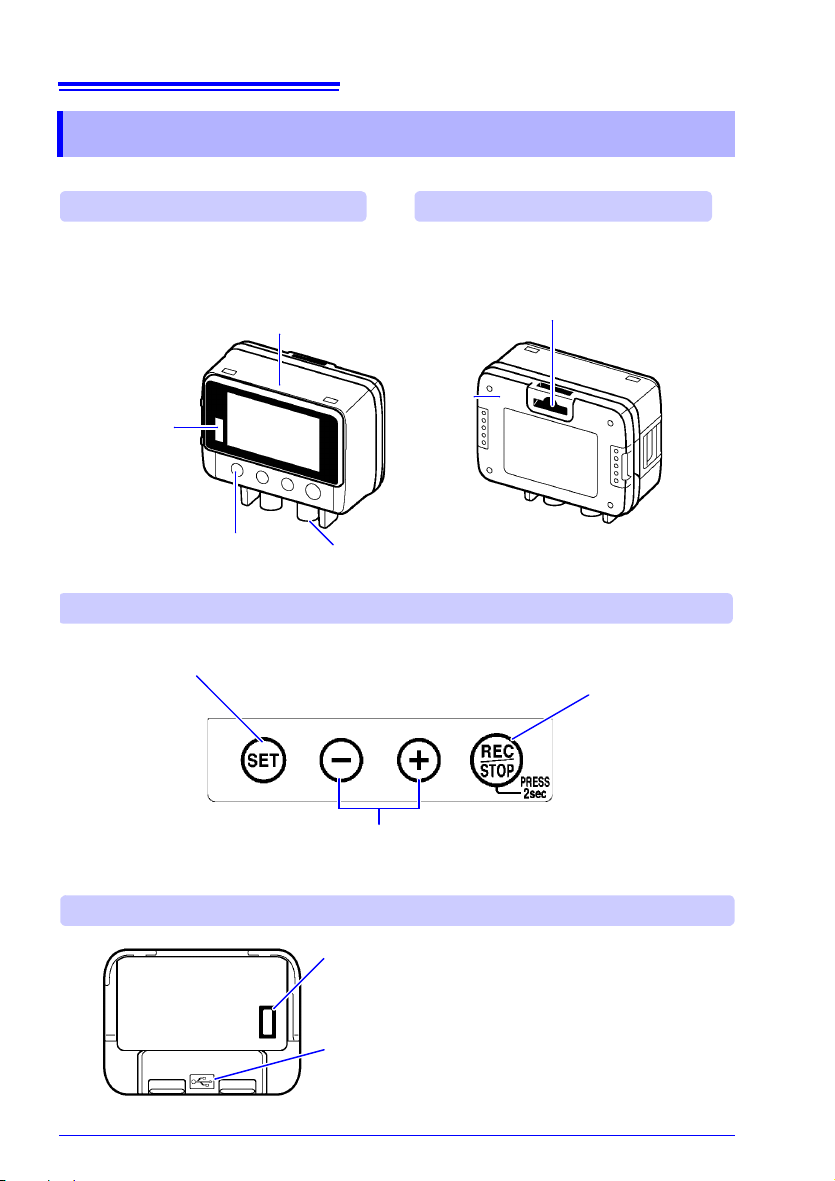
14
IR Port (p.55)
Communicates
with the LR5091
Communication
Adapter or
LR5092-20 Data
Collector.
Front
LCD (p.15)
The display blanks after 30 seconds of operator inactivity (auto power save). The display
reappears by pressing a button.
When the display is visible, it refreshes about
once per second.
Battery
Cover
(p.19)
SET button
Displays settings.
Back
Operating Buttons
Sensor Jacks (p.22)
Connect a clamp sensor.
Operating
Buttons
LR5091 Communication Adapter
IR Port (p.55)
Communicates with the logger.
USB Port (p.43)
Connect a USB cable here to communicate with a
computer. (Mini-B receptacle)
Stand/Strap Attachment Hole (p.52)
Attach the logger to a wall or other surface by
hanging it on a screw. (Supported screw head
dimensions: up to approx. 6.8 mm in diameter
and approx. 2.5 mm in thickness)
REC/STOP button
Hold for two seconds to start/stop recording.
From a setting display, switches to measurement display.
(-) button, (+) button
Changes Measurement display contents.
Changes setting values on the Settings display.
1.2 Part Names/Functions and Display Indicators
1.2 Part Names/Functions and Display Indicators
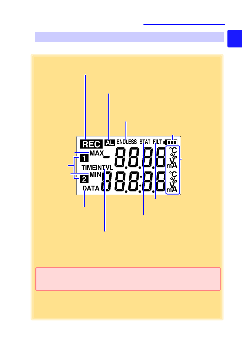
15
REC Indicator
Indicates recording in progress. (Blinks when waiting to record.)
ENDLESS indicator
Indicates the Stop Method Setting display.
Also appears on the Measurement display to indicate
endless recording (p. 29) is enabled.
STAT indicator
Indicates the Recording Mode Setting display.
Also appears on the Measurement display to
indicate statistic recording (p. 29) is enabled.
Battery Status Indicator
Indicates the battery charge status. (p.20)
Units
Indicates the unit of
measurement on
each channel.
Measurement
Channel
MAX indicator
Indicates that the
value displayed at
the right is the maximum.
MIN indicator
Indicates that the
value displayed at
the right is the minimum.
DATA indicator
Indicates that the value displayed
at the right is the data count.
Setting is available from the LR5000 Utility Program or via the LR5092-20 Data Collector.
See: "3.3 Making Settings from the LR5000 Utility Program" (p.43), LR5092-20 Data Col-
lector Instruction Manual
TIME indicator
Indicates the Date-Time Setting display.
INTVL indicator
Indicates the Recording Interval Setting
display.
AL indicator
When the alarm* function is enabled, this indicates when a measured value is outside of the specified (upper/lower value*) range.
FILT ind icat or
Indicates filter setting display.
1.2 Part Names/Functions and Display Indicators
Display Indicators
The display indicators provide the following information.
1
Chapter 1 Overview
3
16
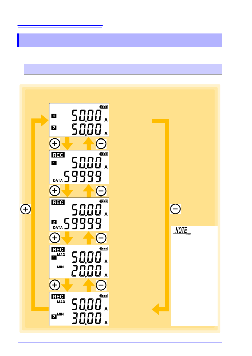
Channel 1
measured value
Channel 2
measured value
Channel 1
maximum value
Channel 1
minimum value
Channel 2
maximum value
Channel 2
minimum value
Example: Two-channel measurement in
the 50 A range
Channel 1
measured value
Recorded data count
Channel 2
measured value
Recorded data count
• For instantaneous
recording, the maximum and minimum
values are obtained
from all the data
measured at each
recording interval.
• For statistical r ecor ding, the maximum
and minimum values are obtained
from all the data
measured every second.
• The maximum and
minimum values are
not displayed when
the recorded data
count is 0.
1.3 Display Organization
1.3 Display Organization
The logger has two general display types: Measurement and Settings.
Measuring display
The (+) and (-) buttons switch the display type.
17
Recording Interval Setting
(p.37)
Year Setting (p.38)
Month Setting (p.38)
Day Setting (p.38)
Stop Method Setting
*1
(p.39)
Minute Setting (p.38)
Hour Setting (p.38)
Measuring display
See: Footnotes *1 to *3 are on the next page.
Filter Setting (p.42)
Power Save Setting
*3
(p.40)
Recording Mode Setting
*
2
(p.40)
Channel 1 Range Setting
(p.41)
Channel 2 Range Setting
(p.41)
Example: Two-channel measurement with the
CT6500 in the 50 A range
1.3 Display Organization
Setting Display
Select the display with the SET button. Press (+) and (-) to change a setting.
Press the REC/STOP button to switch to the Measurement display from any other.
1
Chapter 1 Overview
3

18
1.3 Display Organization
1: Select what happens when memory becomes full. When on, the oldest data is
overwritten, and when off, recording stops. (Default is on.)
2: When on (statistical recording), instantaneous, maximum, minimum, and average
values are recorded at each interval. Battery life is shorter. (Default is off.) (R ecord
instantaneous values)
3: Battery life is extended when on (enabled). (Default is on.)
See:"Appendix 3 Battery Life Approximation" (p.A2)
• When no operation occurs for 30 seconds with the Settings display,
automatically switches to Measurement display.
• When the battery indicator appears, settings cannot be changed
(although they can still be displayed).
• Settings cannot be changed while recording. However, settings can
still be displayed by pressing the SET button from the Measurement
display.
19
1. All segments
2. Model name 3. Firmware version
4. Year Setting display
2.1 Installing (or Replacing) the Battery
Measurement
Preparations Chapter 2
2
2.1 Installing (or Replacing) the Battery
•
After replacing the battery, replace the cover before using the logger .
• Battery may explode if mistreated. Do not short-circuit, recharge,
disassemble or dispose of in fire.
•
Handle and dispose of batteries in accordance with local regulations.
Do not mix old and new batteries, or different types of batteries. Also,
be careful to observe battery polarity during installation. Otherwise,
poor performance or damage from battery leakage could result.
• Data and settings stored in the logger are retained even when the battery is depleted, and during battery replacement.
• Once the battery indicator appears, operation can still continue for
about 30 seconds when the battery is removed during recording.
• Testing monitor batteries installed in the unit may possibly be weak.
Rep
lace batteries before extended measurement usage.
• Use only LR6 Alkaline batteries. Using manganese batteries may not
result in accurate measurements or proper communication with the
LR5091 Communication Adapter and LR5092-20 Data Collector.
• After installing the batteries, the following displays appear, and the
d
ate and time need to be set.
(p.38)
Chapter 2 Measurement Preparations
3
• When the battery indicator appears, settings cannot be changed
(although they can still be displayed).

20
2.1 Installing (or Replacing) the Battery
• When battery voltage is too low to operate the logger, the following
appears. Replace the battery to restore normal operation.
Battery Status Indicator
This indicator is displayed at the top right corner.
Battery charge remains. Fewer blocks within the indicator signify weaker battery charge.
Replace the discharged battery as soon as possible. (Even when the battery is removed
during recording, operation can continue for about 30 seconds.)
The battery is exhausted. In this state, recording and communication with the LR5091
Communication Adapterr and LR5092-20 Data Collector are not possible.
Using a NiMH Battery
The battery status indicator does not accurately show the remaining battery capacity
wh
en using a NiMH battery. Moreover, the battery life will vary greatly with the capacity, charging conditions and repeated uses. Please take note of these points when
using it.
The device's battery status display and battery life are based on the usage of a brandnew alkaline battery.
When the logger will not be used for long time
To avoid corrosion and damage to this instrument from battery leakage,
remove the batteries from the instrument if it is to be stored for a long
time (1 week).
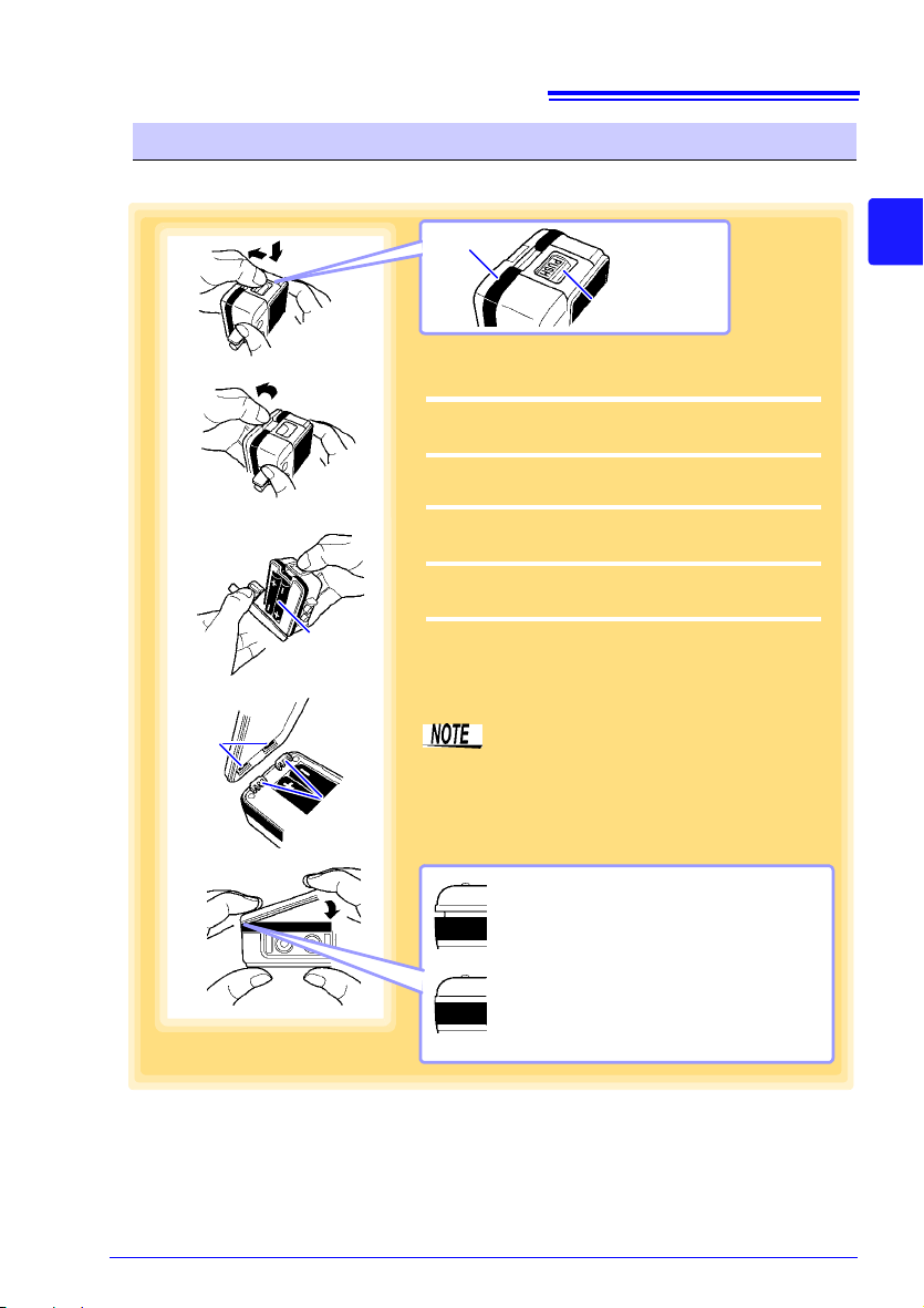
1
3
The cover will not close correctly if
there are any gaps.
Never attempt to force the battery
cover closed when not aligned
properly. Doing so could cause
damage.
NG
Battery
4
Projections
Holes
OK
Push the tab
Battery cover
2
5
1
Press the PUSH tab as shown, and pull the
battery cover back.
2
Hold the battery cover while separating it from
the logger
3
Install the battery as shown.
4
Align the holes in the battery cover with the
projections on the back of the logger.
5
While confirming that there are no gaps, press
with your fingers to close the battery cover.
When the battery is installed, the logger turns
on.
(there is no power switch)
Note that the battery cover is designed
to seal tightly to preserve dust- and dripresistance.
When the holes in the battery cover are
properly aligned with the projections,
the battery cover should close smoothly.
Battery Replacement
Required Items: LR6 alkaline battery (1)
21
2.1 Installing (or Replacing) the Battery
2
Chapter 2 Measurement Preparations
3
22
Clamp Sensor Maximum input current
9695-02 Clamp On Sensor 60 A
CT6500 Clamp On Sensor 600 A
9669 Clamp On Sensor 1000 A
9675 Clamp On Leak Sensor 10 A
9657-10 Clamp On Leak Sensor
10 A
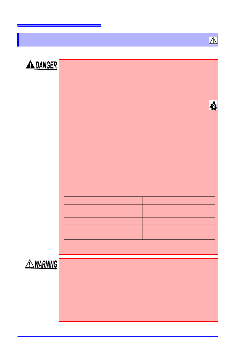
2.2 Connecting a Clam p Sensor
2.2 Connecting a Clamp Sensor
Connect a clamp sensor to the logger's sensor jacks.
• Connect the clamp sensors to the instrument first, and then to
the active lines to be measured.
Observe the following to avoid electric shock
• When the clamp sensor is opened, do not allow the metal part of
the cl
amp to touch any exposed metal, or to short between two
lines, and do not use over bare conductors.
• Use the appropriate cla
the maximum voltage shown:
9695-02 Clamp On Sensor: CAT
CT6500 Clamp On Sensor: CAT
9669 Clamp On Sensor: CAT
9675 Clamp On Leak Sensor: CAT
9657-10 Clamp On Leak Sensor: CAT
Or over bare conductors.
• Clamp sensor should only be connect
a breaker, so the breaker can prevent an accident if a short circuit occurs. Connections should never be made t
side of a breaker, because unrestricted current flow could cause
a serious accident if a short circuit occurs.
• During use, do not touch the end of the sensor beyond the protective barrier.
• Maximum clamp sensor input current is as follows: (At 45 to 66 Hz)
mp sensor for electrical circuits with
III AC300 V
III AC600 V
III AC600 V
and short circuits.
III AC300 V
III AC300 V
ed to the secondary side of
o the primary
Never exceed this limit, as doing so could result in destruction of
the instrument and personal injury or death.
• To avoid electric shock when measuring live lines, wear appropriate protective gear, such as in
and a safety helmet.
• To avoid electric shock when measuring using the
wire for transformer class B grounding work, ensure that the
grounding wire is not near high-voltage devices and wires. In a
location in which measurement is difficult because the grounding wire is near high-voltage live p
grounding wire and then perform measurement. (when using the
9657-10, 9675 Clamp On Leak Sensor)
sulated rubber gloves, boots
grounding
arts, change the routing of the

23
2.2 Connecting a Clamp Sensor
• When disconnecting the BNC connector, be sure to release the lock
before pulling off the connector. Forcibly pulling the connector without
releasing the lock, or pulling on the cable, can damage the connector.
• Do not connect or disconnect when the logger is on, or when clamped
a
round a conductor. Otherwise, the logger or clamp sensor could be
damaged.
• To avoid breaking the cables, do not bend or pull them.
• Avoid stepping on or pinching cables, which could damage the cable
lation.
insu
• To avoid damage to the instrument, protect it from physical shock
when transporting and handling. Be especially careful to avoid physical shock from dropping.
• Be careful to avoid dropping the clamp sensor or otherwise subjecting
th
em to mechanical shock, which could damage the mating surfaces
of the core and adversely affect measurement.
• Keep the clamp jaws and core slits free from foreign objects, which
co
uld interfere with clamping action.
• Keep the clamp closed when not in use, to avoid accumulating dust or
dirt on the mating core surfaces, which could interfere with clamp performance.
• Do not over-tighten the output terminal screws on the 9695-02 Clamp
On
Sensor Proper torque is about 0.5 Nm.
• To replace the output terminal screws of the 9695-02 Clamp On Sensor, use M3x5 screws with captive spring washers. Using other
scr
ews may damage the clamp sensor.
• To avoid damage to t he instrument, do not short- circuit the sensor jack
and do not input voltage to the sensor jack.
• Note that the instrument may be damaged if the applied current
exceeds the measurement range.
• When the power is turned off, do not apply current to the sensor jack.
Doing so may damage the instrument and clamp sensor.
• Note that the instrument and clamp sensor may be damaged if current
exceeding the selected measurement range is applied for a long time
• Measurements are degraded by dirt on the mating surfaces of the
clamp-on sensor, so keep the surfaces clean by gently wiping with a
soft cloth.
2
Chapter 2 Measurement Preparations
3
• When connecting the cable to the output terminals of the 9695-02
Clamp On Sensor, keep the twist as close to the terminals as possible, to minimize the effects of external magnetic fields.
• Use only the special-purpose 9219 Connection Cable to connect the
9695-02 Clamp On Sensor to the logger. (The connectors on the 9219
re solderless terminals and a BNC plug.)
a

24
1
Align the slots in the BNC plug on the sensor
cable with the pins in the jack on the logger.
2
Push and turn clockwise to lock.
To disconnect, push and turn the plug counterclockwise, then pull out.
Values are not displayed correctly if the sensor
plug is not inserted far enough.(See the 50 A range
example below.)
If values are not displayed correctly even when the
plug is inserted properly, the logger or sensor may
be damaged. Repair may be necessary.
See: "Requesting repairs" (p.97)
Lock
Pins in the
jack
Slots in the
BNC plug
1
2
2.2 Connecting a Clam p Sensor
Connecting to the Logger
Required Items: Hioki Clamp sensors (See: "Options" (p.4))
Compatible Clamp Sensors
9695-02 Clamp On Sensor,CT6500 Clamp On Sensor,
9669 Clamp On Sensor,9675 Clamp On Leak Sensor,
9657-10 Clamp On Leak Sensor
Note: The 9219 Connection Cable is required to connect the 9695-02 Clamp On Sensor.
 Loading...