

Page 1

L9788-10, L9788-11
スイッチ付きリード
TEST LEAD
WITH REMOTE SWITCH
取扱説明書 / Instruction Manual
Oct. 2020 Revised edition 2
L9788F980-02 20-10H
JA/EN
安全について
隙間のないように
しっかり差し込む
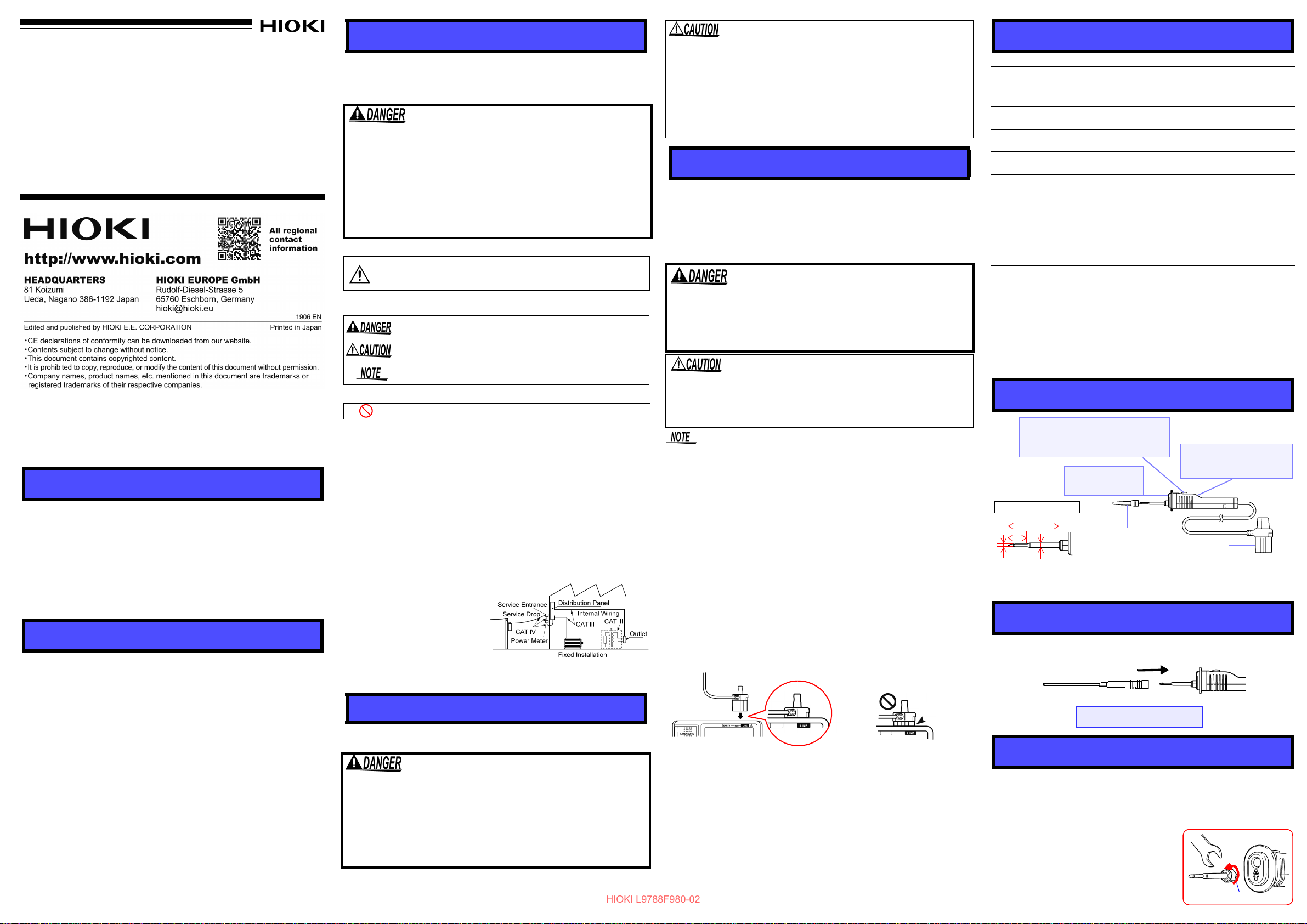
単位:mm
先端拡大図
ø3.2
MEASURE キー
絶縁抵抗測定のときに押します。
本体の活線警告表示と連動して赤
色に点灯します。
判定表示器
コンパレータの判定結果を表示
します。PASS のときは緑色、
FAIL のときは赤色に点灯します。
ライト
本体のバックライトと
連動します。
プラグ
キャップ
35
13
ø1.8
:判定表示器は、デジタル形の IR4050 シリーズと
組み合わせたときに、判定結果を表示します。
アナログ形の IR4000 シリーズでは動作しません。
本器のキャップを外してから、ブレーカピン(L9788-92)を取り付けてください。
奥までしっかり差し込んでください。
取り外すとき
HIOKI L9788F980-02
この取扱説明書には本器を安全に操作し、安全な状態に保つのに要す
る情報や注意事項が記載されています。本器を使用する前に下記の安
全に関する事項をよくお読みください。
この機器は IEC 61010 安全規格に従って、設計され、試験し、安全
な状態で出荷されています。測定方法を間違えると人身事故や機器
の故障につながる可能性があります。また、本器をこの取扱説明書
の記載以外の方法で使用した場合は、本器が備えている安全確保の
ための機能が損なわれる可能性があります。
取扱説明書を熟読し、十分に内容を理解してから操作してください。
万一事故があっても、弊社製品が原因である場合以外は責任を負い
かねます。
安全記号
注意や危険を示します。機器上にこの記号が表示されている場合
は、取扱説明書の該当箇所を参照ください。
取扱説明書の注意事項には、重要度に応じて以下の表記がされています。
操作や取扱いを誤ると、使用者が死亡または重傷につながる危険
性が極めて高いことを意味します。
操作や取扱いを誤ると、使用者が傷害を負う場合、または機器を
損傷する可能性があることを意味します。
製品性能および操作上でのアドバイス的なことを意味します。
• この機器は室内用に設計されています。安全性を損なわないで
0 ℃~ 50 ℃の温度まで使用できます。
• 本器をぬらしたり、ぬれた手で測定しないでください。感電事故
の原因になります。
• 本器の損傷を防ぐため、運搬および取扱いの際は振動、衝撃を避
けてください。特に、落下などによる衝撃に注意してください。
• 断線による故障を防ぐため、本器の付け根を折ったり引っ張った
りしないでください。
• 本器の先端はとがっているため危険です。けがのないよう、取扱
いには十分注意してください。
使用方法
使用前の確認
使用前には、保存や輸送による故障がないか、点検と動作確認をして
から使用してください。点検箇所としては、ピンの動作、先ピンの緩
みなどがあります。故障を確認した場合は、お買上店(代理店)か最
寄りの営業拠点にご連絡ください。
感電事故を防ぐため、ケーブル内部から白色部分(絶縁層)が露出
していないか確認してください。ケーブル内部の色が露出している
場合は、使用しないでください。損傷がある場合は、感電事故にな
るので、お買い上げ店(代理店)か最寄の営業拠点にご連絡ください。
仕様
L9788-11 は L9788-10 スイ
機能
使用温湿度範囲
使用場所
保存温湿度範囲
最大定格
• キャ
• キャ
• 最大定格電流
ケーブル長
質量
付属品 取扱説明書
オプション
適合規格
L9788-10, L9788-11 は H
ッチ付きリードと EARTH 側リードのセットです。
スイッチ :手持ち部にリモートコントロール用
ライト :手持ち部先端に照明用ライト
判定表示器:コンパレータの判定結果を表示
0 ℃~ 50 ℃、90% rh 以下(
屋内、汚染度 2、高度 2000 m 以下
-20 ℃~ 60 ℃、90% rh 以下(
ップ装着時
ップ未装着時 対地間最大定格電圧 600 V
対地間最大定格電圧 600 V
測定カテゴリⅢ
予想される過渡過電圧 6000 V
測定カテゴリⅡ
予想される過渡過電圧 4000 V
連続)
2 A(
約 1200 mm
約 70 g(L97
L9788-90 先ピ
L9788-92 ブレ
安全 EN61010
IOKI 3490, IR4000 シリーズ専用です。
M
EASURE キー
結露なきこと)
結露なきこと)
88-10)、約 130 g(L9788-11)
ン
ーカピン
はじめに
このたびは、HIOKI L9788-10 スイッチ付きリード、L9788-11 スイッ
チ付きリードセットをご選定いただき、誠にありがとうございます。
この製品を十分にご活用いただき、末長くご使用いただくためにも、
取扱説明書はていねいに扱い、いつもお手元に置いてご使用ください。
概要
L9788-10 スイッチ付きリードは、手持ち部分に MEASURE キー、先
端にライトを搭載した、絶縁抵抗計 3490、IR4000 シリーズ用テスト
リードです。
このテストリードをご使用いただくことにより、測定中、LINE 側テス
トリードを持ったまま測定を開始できます。さらに、先端にライトが
ついていますので暗所でも作業できます。また、ピン先が長いため、ブ
レーカを測定するときに、ほとんどのブレーカでカバーを外すことな
く測定でき、先端が細くなっていますので、ピン先をコンセントに挿
入できます。
点検・保守
点検
本器がお手元に届きましたら、輸送中において異常または破損がない
か点検してからご使用ください。万一、破損あるいは仕様どおり動作
しない場合は、お買上店(代理店)か最寄りの営業拠点にご連絡くだ
さい。
保守・サ-ビス
• 本器の汚れをとるときは、柔らかい布に水か中性洗剤を少量含ませ
•
• 輸送中に破損しないように梱包し、故障内容も書き添えてくださ
て、軽く拭いてください。ベンジン、アルコール、アセトン、エー
テル、ケトン、シンナー、ガソリン系を含む洗剤は絶対に使用しな
いでください。変形、変色することがあります。
故障と思われるときは、お買上店(代理店)か最寄りの営業拠点にご
連絡ください
い。輸送中の破損については保証しかねます。
。
その他の記号
してはいけない行為を示します。
測定カテゴリについて
本器は CAT III に適合しています。
測定器を安全に使用するため、IEC61010 では測定カテゴリとして、使用する
場所により安全レベルの基準を CAT Ⅱ~ CAT Ⅳで分類しています。
CAT Ⅱ:コンセントに接続する電源コード付き機器(可搬形工具・家庭用電気
製品など)の一次側電路。
コンセント差込口を直接測定する場合は CAT Ⅱです。
CAT Ⅲ:直接分電盤から電気を取り込む機器(固定設備)の一次側および分電
CAT Ⅳ:建造物への引込み電路、引込み口から電力量メータおよび一次側電流
カテゴリの数値の小さいクラスの測定器で、数値の大きいクラスに該当する場
所を測定すると重大な事故につながる恐れがありますので、絶対に避けてくだ
さい。
カテゴリのない測定器で、CAT Ⅱ~ CAT Ⅳの測定カテゴリを測定すると重大
な事故につながる恐れがありますので、絶対に避けてください。
本器を安全にご使用いただくために、また機能を十分にご活用いただ
くために、下記の注意事項をお守りください。
盤からコンセントまでの電路
保護装置(分電盤)までの電路
使用上の注意
• 感電事故を防ぐため、本器の先端で電圧のかかっているラインを
短絡しないでください。
• 対地間最大定格電圧は 600 V 以下です。大地に対してこの電圧を
超える測定はしないでください。本器を破損し、人身事故になり
ます。
• 感電
・短絡事故を避けるため、本器を接続する前に各機器の電源
を OFF にしてください。
L9788-10 を絶縁抵抗計に接続した場合も、絶縁抵抗計の MEASURE
キーは有効となっています。L9788-10 を絶縁抵抗計に接続した状態
で、絶縁抵抗計の MEASURE キーを押しても試験電圧が出力されま
すのでご注意ください。
• L9788-10 のライトは、絶縁抵抗計のライトと連動します。
• MEASURE キーは本体の活線警告表示と連動して赤色に点灯します。
• テストリードの先端金属ピンには、取り外し可能なキャップが装着されてい
ます。短絡事故を防ぐため、測定カテゴリ CAT Ⅲで測定するときは、必ず
キャップをつけて使用してください。CAT Ⅱで測定するときは、キャップを
外して使用してください。測定カテゴリについては、取扱説明書の「測定カ
テゴリについて」を参照してください。
• キャップを装着して測定する場合、キャップを損傷しないように注意してく
ださい。測定中に不用意にキャップが外れた場合などは、感電事故を防ぐた
め取り扱いには十分注意してください。
1. 絶縁抵抗計の電源が OFF になっていることを確認します。
2.
本器のプラグを、絶縁抵抗計の
3.
測定前の点検
a. テストリードの先端をショートします。
b. 絶縁抵抗計を絶縁抵抗レンジに設定します。
c. L9788-10 の MEASURE キーを押すと測定値が 0 Ω を表示すること、
L9788-10 の MEASURE キーが、絶縁抵抗計の活線警告表示と連動して赤
色に点灯することを確認してください。
d. 絶縁抵抗計の LIGHT キーを押すと、L9788-10 先端のライトが点灯するこ
とを確認してください。
(本器を使用する前に、次の事項を必ず確認してください)
LINE
端子側に根元までしっかり差し込みます。
4. テストリードを測定対象に接続します。
5. 絶縁抵抗計の設定をします。
6. MEASURE キーを押と測定を開始します。
各部の名称
ブレーカピン ( オプション ) の接続
先ピン ( オプション ) の交換方法
L9788-10 の先端のピンが磨耗したり、折れた場合には交換できます。
先ピン(L9788-90)は別途お買い求めください。
1. 絶縁抵抗計の電源を OFF にし、本器を取り外します。
2. 先ピンをスパナ(7 mm 幅)で回し、取り外します。
3. 新しい先ピンをスパナで回して、本器に取り付けます。
(締付けトルク:0.3 N
4. 動作確認をします。既知の測定対象物を測定し、抵抗値が正確であるか確
認してから使用してください。
•m)
Page 2
Introduction
L9788-10, L9788-11
TEST LEAD
WITH REMOTE SWITCH
Instruction Manual
Oct. 2020 Revised edition 2
L9788F980-02 20-10H
EN
Plug the test lead securely into the
Insulation Resistance Tester.
Yes
No
1.8
3.2
35
Enlarged view of pin
13
Sleeve
Unit: mm
Light
Is linked to the instrument’s backlight.
MEASURE key
Press to measure
insulation resistance.
The MEASURE key is connected with the
Live circuit indicator and will light up as red.
Judgment indicator*
Indicates the comparator judgment result by turning green for
PASS and red for FAIL.
Plug
* When combined with the digital-type IR4050 series, the
evaluation displayer will show the evaluation results.
It will not run with the analog-type IR4000 series.
First take out the sleeve from the test lead, and then install the
Breaker pin (L9788-92)
Plug it all the way to the end.
Turn to remove
HIOKI L9788F980-02
Thank you for purchasing the HIOKI Model L9788-10 Test Lead
with Remote Switch, L9788-11 Test Lead with Remote Switch.
To obtain maximum performance from the instrument, please
read this manual first, and keep it handy for future reference.
Overview
The L9788-10 is a test lead for use with a Model 3490 and IR4000
series Insulation Resistance Tester, equipped with a MEASURE
key at the grip and a light at the front. With this test lead, users can
start the measurement by using the test lead on the LINE side with
their right hand. Furthermore, the light at the front makes it easier
to carry out work in dark areas.
The pin tip is also slightly longer than usual, making it possible to
measure breakers without removing the breaker covers in most
cases, and thinner, allowing it to be inserted into an electrical outlet.
Inspection and Maintenance
Initial Inspection
When you receive the instrument, inspect it carefully to ensure
that no damage occurred during shipping. If damage is evident,
or if it fails to operate according to the specifications, contact
your dealer or Hioki representative.
Maintenance and Service
• To clean the instrument, wipe it gently with a soft cloth moistened with water or mild detergent. Never use solvents such
as benzene, alcohol, acetone, ether, ketones, thinners or
gasoline, as they can deform and discolor the case.
• If the instrument seems to be malfunctioning, contact your
dealer or Hioki representative.
• Pack the instrument so that it will not sustain damage during
shipping, and include a description of existing damage. We cannot accept responsibility for damage incurred during shipping.
Safety
This manual contains information and warnings essential for
safe operation of the instrument and for maintaining it in safe operating condition. Before using it, be sure to carefully read the
following safety precautions.
This instrument is designed to comply with IEC 61010
Safety Standards, and has been thoroughly tested for
safety prior to shipment. However, mishandling during use
could result in injury or death, as well as damage to the
instrument . Using the instrument in a way not described
in this manual may negate the provided safety features.
Be certain that you understand the instructions and precautions in the manual before use. We disclaim any
responsibility for accidents or injuries not resulting
directly from instrument defects.
Safety Symbol
Indicates cautions and hazards. When the symbol is printed on
the product, refer to a corresponding topic in the Instruction
Manual.
The following symbols in this manual indicate the relative importance
of cautions and warnings.
Indicates that incorrect operation presents an extreme hazard that could result in serious injury or death to the user.
Indicates that incorrect operation presents a possibility of
injury to the user or damage to the instrument.
Indicates advisory items related to performance or correct operation of the instrument.
Other Symbol
Indicates a prohibited action.
Measurement categories
This instrument complies with CAT III safety requirements.
To ensure safe operation of measurement instruments, IEC 61010 establishes safety standards for various electrical environments, categorized as CAT II to CAT IV, and called measurement categories.
CAT II: Primary electrical circuits in equipment connected to an AC
CAT III: Primary electrical circuits of heavy equipment (fixed installa-
CAT IV: The circuit from the service drop to the service entrance, and
Using a measurement instrument in an environment designated with a higher-numbered
category than that for which the
instrument is rated could result
in a severe accident, and must
be carefully avoided.
Use of a measurement instrument that is not CAT-rated in
CAT II to CAT IV measurement applications could result in a severe accident, and must be carefully avoided.
electrical outlet by a power cord (portable tools, household appliances, etc.)
CAT II covers directly measuring electrical outlet receptacles.
tions) connected directly to the distribution panel, and feeders
from the distribution panel to outlets.
to the power meter and primary overcurrent protection device
(distribution panel).
Usage Notes
Follow these precautions to ensure safe operation and to obtain
the full benefits of the various functions.
• To avoid electrical shock, be careful to avoid shorting
live lines with the pin.
• The maximum rated voltage between input terminals and
ground is 600 V. Attempting to measure voltages exceeding these limits with respect to ground could damage the
ins
trument and result in personal injury.
• To avoid shock and short circuits, turn off all power
fore connecting leads.
be
• This instrument is designed for use indoors. It can be operated
at temperatures between 0 and 50°C without degrading safety.
• Do not allow the instrument to get wet, and do not take measurements with wet hands. This may cause an electric shock.
• To avoid damage to the instrument, protect it from physical
shock when transporting and handling. Be especially careful to
avoid physical shock from dropping.
• To avoid breaking the leads, do not bend or pull them.
• The ends of the leads are sharp. Be careful to avoid injury.
Procedure
Preliminary Checks
Before using the instrument the first time, verify that it operates normally
to ensure that no damage occurred during storage or shipping. Points to
check include the pin operation and whether the pin and cable lock are
loose. As loose screwing of the cable lock and other components can result in damage, be sure to tighten them securely before use.
If you find any damage, contact your dealer or Hioki representative.
To prevent an electric shock accident, confirm that the
white portion (insulation layer) inside the cable is not
exposed. If a color inside the cable is exposed, do not
use the cable. Using the instrument in such conditions
could cause an electric shock, so contact your dealer or
Hioki representative for repair.
The Insulation Resistance Tester’s MEASURE key will still be
available even when this test lead is connected to the Insulation
Resistance Tester. When connected to the Insulation Resistance Tester, take note that a test voltage will be discharged
even when the MEASURE key of the Tester is pressed.
• The light of this instrument is connected with the Insulation
Resistance Tester’s Light.
• The MEASURE key is connected with the Live circuit indicator
and will light up as red.
• Removable sleeves are attached to the metal pins at the ends of
the test leads. To prevent a short circuit accident, be sure to use
the test leads with the sleeves attached when performing measurements in the CAT III a measurement category. Remove the
sleeves from the test leads when performing measurements in the
CAT II measurement categories.For details on measurement categories, see “Measurement categories” in the instruction manual.
• When performing measurements with the sleeves attached, be
careful to avoid damaging the sleeves. If the sleeves are inadvertently removed during measurement, be especially careful in
handling the test leads to avoid electric shock.
1.Confirm that the power of the Insulation Resistance Tester is
turned off.
2.Plug the test lead securely into the LINE terminal of the Insulation Resistance Tester.
3.Before Starting (Before using the test leads, be sure to conduct
the following safety checks.)
a. Short circuit the tips of the test leads.
b. Turn the function switch of the Insulation Resistance Tester to
one of the Insulation Resistance Measurement functions.
c. Press the MEASURE key on the L9788-10 Test Leads and
confirm that:
• 0 is indicated on the Insulation Resistance Tester; and
• Upon pressing the MEASURE key on the L9788-10, the MEASURE key lights up in red.
d. When pressing the LIGHT key on the Insulation Resistance
Tester, the light at the tip of the L9788-10 Test Leads turns ON.
4.Connect the test lead to the object to be measured.
5.Carry out settings on the Insulation Resistance Tester.
6.Press the MEASURE key to start the measurement.
Specifications
Model L9788-11 is a set of Model L9788-10 and EARTH side lead.
Functions Switch: MEASURE key for remote control grip
Operating temperature
and humidity
Operating Environment Indoors, Altitude up to 2000 m (6562 feet),
Storage temperature
and humidity
Maximum rated
• Sleeves attached Maximum rated voltage to earth 600 V
• Sleeves removed
• Maximum rated current
Cable length Approx. 1200 mm (47.24”)
Mass Model L9788-10: Approx. 70g (2.5 oz.)
Accessory Instruction manual
Options L9788-90 Tip Pin
Applicable Standards Safety EN61010
Model L9788-10, L9788-11 is provided exclusively for the Hioki Model 3490 and
IR4000 series.
Light : Light at the tip of the at the grip
Judgment indicator : Indicates the comparator
0
°C to 50°C (32°F to 122°F), 90% RH or less
(no condensation)
Pollution degree 2
-20°C to 60°C (-4
(no condensation)
Measurement category III
Anticipated transient overvoltage 6000 V
Maximum rated voltage to earth 600 V
Measurement category II
Anticipated transient overvoltage 4000 V
2A (continuous)
Model L9788-11: Approx. 130g (4.6 oz.)
L9788-92 Breaker Pin
judgment result
°F to 140°F), 90% RH or less
Parts Names
Breaker Pin (Option) Connection
Replacing the Tip Pin (Option)
The pin at the front of the test lead can be replaced when it has worn away
or is damaged. Please order the replacement pins (Model L9788-90).
1. Turn off the power of the Insulation Resistance Tester and disconnect the test leads.
2.Rotate the tip pin with a spanner (7 mm width) to remove it.
3.Turn the new tip pin with a spanner and
attach it to the test leads.(tightening
torque : 0.3N
4. Check the performance. Measure an
object with a known resistance. Make
sure that the measured resistance is
correct before using the L9788-10.
•m)
 Loading...