

Page 1
PIN TYPE LEAD
Instruction Manual
L2020
EN
May 2016 Revised edition 1
Printed in Japan
L2020A961-01 16-05H
Introduction
Thank you for purchasing the Hioki L2020 Pin Type Lead. To
obtain maximum performance from the device, please read
this manual first, and keep it handy for future reference
Safety Information
Before using the device be certain to carefully read the
following safety notes:
Usage Notes
Follow these precautions to ensure safe operation and to
obtain the full benefits of the various functions
Overview
The L2020 Pin Type Lead has a 4-terminal structure that
can be used in small spaces where there may be difficulty
in contacting an object to be measured, such as during
emergency battery maintenance.
Since the conductor contact pins have an outside diameter of
2.9 mm, they can be used to measure batteries via the battery
terminal cover’s test holes without needing to remove the
cover.
Inspection and Maintenance
Initial Inspection
When you receive the device, inspect it carefully to ensure that
no damage occurred during shipping. If damage is evident, or
if it fails to operate according to the specifications, contact your
authorized Hioki distributor or reseller.
Maintenance and Service
• To clean the device, wipe it gently with a soft cloth moistened
with water or mild detergent.
• If the device seems to be malfunctioning, contact your
authorized Hioki distributor or reseller.
Transporting the device
During shipment of the device, handle it carefully so that it is
not damaged due to a vibration or shock.
Disposal
Handle and dispose of the device in accordance with local
regulations.
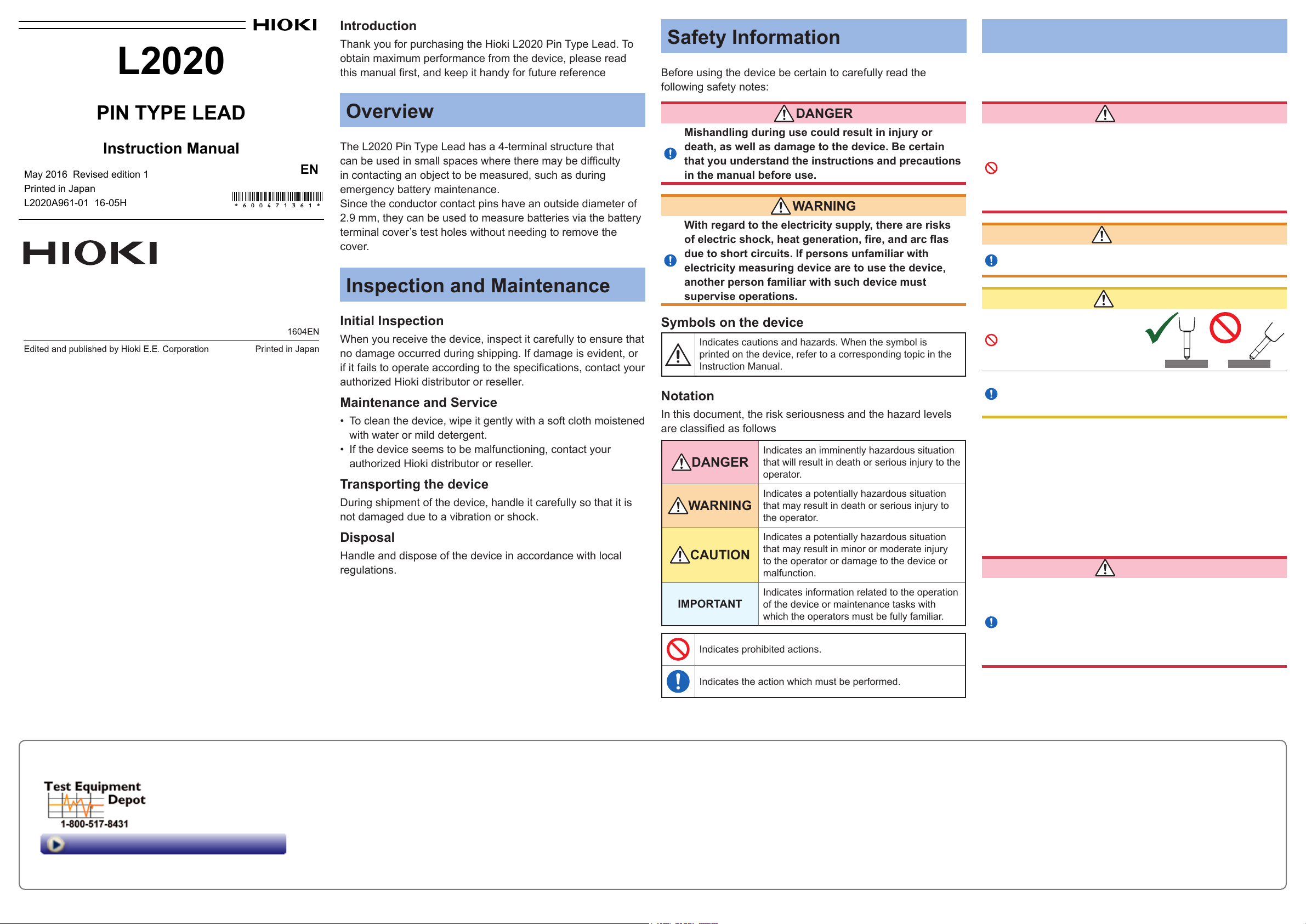
DANGER
Mishandling during use could result in injury or
death, as well as damage to the device. Be certain
that you understand the instructions and precautions
in the manual before use.
WARNING
With regard to the electricity supply, there are risks
of electric shock, heat generation, fire, and arc flas
due to short circuits. If persons unfamiliar with
electricity measuring device are to use the device,
another person familiar with such device must
supervise operations.
Symbols on the device
Indicates cautions and hazards. When the symbol is
printed on the device, refer to a corresponding topic in the
Instruction Manual.
Notation
In this document, the risk seriousness and the hazard levels
are classified as follows
Indicates an imminently hazardous situation
DANGER
WARNING
CAUTION
IMPORTANT
Indicates prohibited actions.
that will result in death or serious injury to the
operator.
Indicates a potentially hazardous situation
that may result in death or serious injury to
the operator.
Indicates a potentially hazardous situation
that may result in minor or moderate injury
to the operator or damage to the device or
malfunction.
Indicates information related to the operation
of the device or maintenance tasks with
which the operators must be fully familiar.
DANGER
• To avoid electric shock, be careful to avoid
shorting live lines with the device.
• Do not use the device and measuring instrument
with circuits that exceed its ratings or
specifications. Doing so may damage the device or
measuring instrument, resulting in electric shock.
WARNING
To avoid shock and short circuits, turn off all power
before connecting the device.
CAUTION
• To avoid damage, do not
contact the L2020 tip
against the battery at a
tilted angle.
• To avoid damage to the L2020, protect it from physical
shock when transporting and handling. Be especially
careful to avoid physical shock from dropping.
OK
NO
Preliminary Checks
Verify that the device operates normally to ensure that no
damage occurred during storage or shipping. If you find any
damage, contact your authorized Hioki distributor or reseller.
Points to check: conductive contact pin operation and whether
the pin tip is loose
As loose the pin tip can result in damage, be sure to tighten it
securely before use.
DANGER
Before using the device, make sure that the
insulation on the test leads is undamaged and that
no bare conductors are improperly exposed. Using
the device in such conditions could cause an electric
shock, so contact your authorized Hioki distributor
or reseller for repair.
Memo
Visit us at www.TestEquipmentDepot.com
Indicates the action which must be performed.
99 Washington Street
Melrose, MA 02176
Phone 781-665-1400
Toll Free 1-800-517-8431
Page 2
Procedure
Make sure that power of the instrument to connect
1
the L2020 to is off.
Connect the L2020 to
2
Black
the input terminal of the
instrument.
Perform zero adjustment.
3
Be sure to use a zero
adjustment board which is
the accessory or option of
connectable instrument.
(See the instruction manual for
details of connectable devices.)
Connect the L2020 to a sample.
4
SOURCE
Zero adjustment board
Red
Align the similarly
colored marks.
SENSE
Part Names
(3)
(2)
(1)
(1) Protective cap
Remove this cap before use.
Reattach the cap when not using the lead.
(2) Conductive contact pin
(3) Grip
(4) SOURCE connector
(4)
(5)
(1)
Specification
General Specification
Operating
environment
Operating temperature
and humidity
Storage temperature
and humidity
Dimensions Approx. 1950 mm (76.77″)
Mass Approx. 210 g (7.4 oz.)
Accessory Instruction manual
Option Model 9465-90 Tip Pin
Basic Specification
Rated current 2 A AC/DC continuous
Maximum rated
voltage to earth
Measurement
connector
Indoors, Pollution Degree 2, altitude up
to 2000 m (6562 ft.)
0°C to 40°C (32°F to 104°F),
80% RH or less (no condensation)
-10°C to 50°C (14°F to 122°F),
80% RH or less (no condensation)
Effective value 30 V, Peak value 42.4 V,
Direct current 60 V
SOURCE Hi, SOURCE Lo, SENSE Hi,
SENSE Lo
No GUARD connector
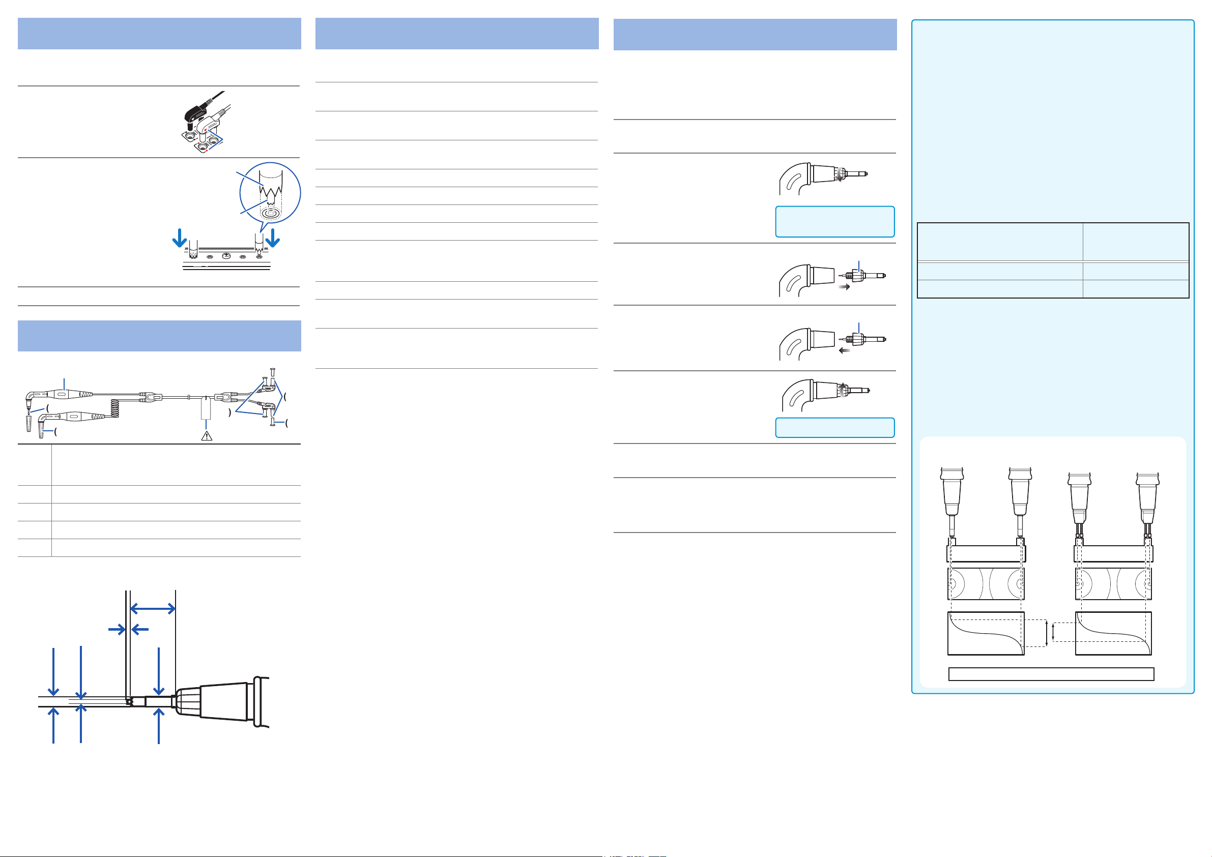
Replacing the Pin Tip (Option)
The conductive contact pin is replaceable. Replace the pin
with a new one if it is broken or worn. Purchase the 9465-90
Pin Tip, which includes the conductor contact pin and the pin
base (plastic portion).
Turn off the power of the instrument and remove
1
the L2020.
Rotate the grip to loosen
2
it.
Beware of injury.
The tip has a sharp point.
Remove the pin tip.
3
Replace the pin tip to a
4
new one.
Rotate the grip to fasten
5
it.
Be sure to fasten it tightly.
To avoid broken wires and contact failures, check
6
that the cable is firmly held
Check the performance.
7
Measure an object with a known resistance. Make sure that
the measured resistance is correct before using the pin type
lead.
9465-90 Pin Tip
9465-90 Pin Tip
IMPORTANT
Measurement values when using 4-terminal measurement
(Differences in measurement values due to pin type leads
used)
Depending on the subject of measurement, such as a lead-acid
battery, measurement values may vary due to the pin type lead
used. Since these differences in measurement values are due to
the shapes and dimensions of the pin type leads used in 4-terminal
measurement, measurement values taken using any pin type lead
represent the true values for that pin type lead only.
When judging battery wear using changes in resistance values with
time, be sure to use pin type leads having the same dimensions.
Reference example: measurement of an MSE-200 valve-regulated
stationary lead-acid battery
(Resistance values vary according to the materials and structure of
the terminals of the subject of measurement.)
Pin type lead (Distance between
the current-impression pin and the
voltage-measurement pin)
L2020 Pin Type Lead (0.65 mm) 0.538 m
9772 Pin Type Lead (2.5 mm) 0.490 m
See the BT3554 Battery Tester Instruction manual for detailed
technical descriptions.
Explanation
Differences in measurement values are physical phenomena
resulting from differences in the distances (dimensions) between
current-impression pins and voltage-measurement pins. The
greater the battery terminal resistance in comparison to the
battery's internal resistance, the more marked these differences
become. The following diagram shows how differences in voltage
detected result from differences in distance when measuring a
lead-acid battery.
Model L2020
(Pin distance: 0.65 mm)
+
−
Measurement values
using the BT3554
Battery Tester
Ω
Ω
Model 9772
(Pin distance: 2.5 mm)
+ −
(5) SENSE connector
Enlarged view of pin
1
1.27
2.7
φ
φ
13.5
φ
2.9
Unit: mm
Lead-acid battery Lead-acid battery
Equipotential line Equipotential line
B
A
Potential gradient Potential gradient
V (voltage detected): A>B
 Loading...