

Page 1
L2002
HIOKI L2002A981-01
CLIP TYPE PROBE
Instruction Manual
Sept. 2020 Revised edition 1
L2002A981-01 20-09H
EN
Inspection/Maintenance
When you receive the product, inspect it carefully to ensure
that no damage occurred during shipping. If damage is
evident, or if it fails to operate according to the specications,
contact your authorized Hioki distributor or reseller.
Preliminary checks
WARNING
Before using the product, ensure that the insulation on
the probes are not damaged and conductors are not
exposed. Using the product in such conditions could
cause an electric shock, so contact your authorized
Hioki distributor or reseller for repair.
Maintenance and service
IMPORTANT
Never use cleaning agents containing benzene, alcohol,
acetone, ether, ketones, thinners or gasoline. These can
deform and discolor the case.
• To clean the product, wipe it gently with a soft cloth moistened with
water or mild detergent.
• If the product seems to be malfunctioning, contact your authorized
Hioki distributor or reseller. Pack the product so that it will not get
damaged during shipping, and include a description of existing
damages. Hioki cannot be responsible for damage that occurs
during shipment.
Disposal
Handle and dispose of the product in accordance with local
regulations.
Operating Precautions
Installing the product in inappropriate locations may cause
the probe to malfunction or lead to accidents. Please do not
install in the following locations. For details on the operating
temperature and humidity, see the specications.
WARNING
• Exposed to direct sunlight or high temperatures
• Exposed to corrosive or combustible gases
• Exposed to strong electromagnetic elds or
electrostatic charges
• Near induction heating systems (such as highfrequency induction heating systems and IH cooking
equipment)
• Susceptible to vibration
• Exposed to water, oil, chemicals, or solvents
• Exposed to high humidity or condensation
• Exposed to high quantities of dust particles
Safety Information
Before using the product, be certain to carefully read the
following safety notes.
WARNING
•
Customers are not allowed to modify, disassemble
or repair the instrument. Failure to observe these
precautions may result in re, electric shock, or injury.
•
Ensure that the input does not exceed the maximum
input voltage or current to avoid product damage
resulting from heat building. Excessive voltage and
current can cause the product to malfunction.
,
CAUTION
• Mishandling during use could result in injury or death
as well as damage to the product. Be certain that you
understand the instructions and precautions in the
manual before use.
• If persons unfamiliar with electricity measuring product
are to use the product, another person familiar with
such instruments must supervise operations.
Safety symbols
Indicates cautions and hazards. When the symbol is
printed on the product, refer to a corresponding topic
in the Instruction Manual.
Indicates DC (Direct Current).
Notation
In this manual, the risk seriousness and the hazard levels are
classied as follows.
Indicates a potentially hazardous situation that may
WARNING
CAUTION
IMPORTANT
result in death or serious injury to the operator.
Indicates a potentially hazardous situation that
may result in minor or moderate injury to the
operator or damage to the product or malfunction.
Indicates information related to the operation of
the product or maintenance tasks with which the
operators must be fully familiar.
Indicates a prohibited action.
Indicates actions which must be performed.
,
Overview
L2002 Clip Type Probes are four-terminal probes suitable for
measuring laminate type batteries. The same clipping depth
can be always maintained by using a positioning stopper.
Terminal structure Gold-plated process
Tip shape: spherical surface
Used tip pin can be replaced.
Distance between pins 6.3 mm (0.25″)
Operating temperature
and humidity
Storage temperature
and humidity
Operating environment Indoors, Pollution degree 2, altitude up to
Product warranty period 1 year
Accessories Return Cable (400 mm)
Temperature; 0°C to 40°C (32°F to 104°F),
Humidity; 80% RH or less (no condensation)
Temperature; -10°C to 50°C (14°F to 122°F),
Humidity; 80% RH or less (no condensation)
2000 m (6562 ft.)
Return Cable (550 mm)
Return Cable (800 mm)
Instruction Manual
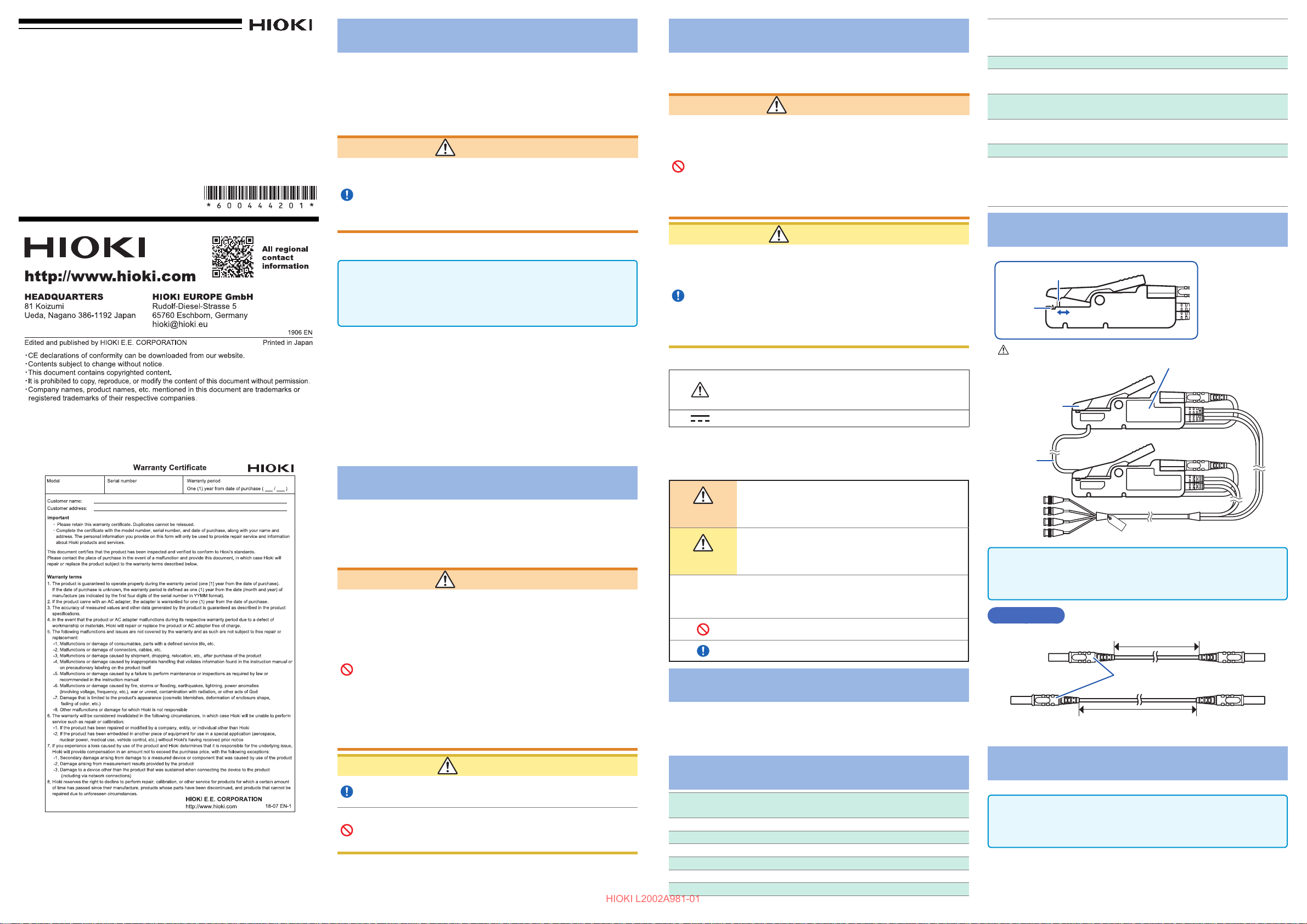
Part Names
Positioning stopper
Tip pin
Probe’s maximum rating is 30 V, but be careful to avoid
exceeding the maximum rating of the measuring instrument.
Rubber
Red (HIGH)
Return
Cable
(550 mm)
Black (LOW)
IMPORTANT
Return Cable (550 mm) is shipped in a state connected to
the instrument.
Accessories
400 mm
Plug
800 mm
Introduction
Thank you for purchasing the HIOKI L2002 Clip Type Probe.
To obtain maximum performance from the product please
read this manual rst, and keep it handy for future reference.
CAUTION
The ends of the probes are sharp. Be careful to avoid
injury.
To prevent probe damage, do not step on probes or
pinch them between other objects. Do not bend or pull
on probes at their base.
Specifications
Measurable frequency
range
Maximum rated voltage 30 V peak
Maximum rated current 2.5 A peak
Structure Four-terminal pair connection structure
Length Approx. 1500 mm (59.06″)
Mass Approx. 220 g (7.8 oz.)
Cable used 50
DC to 1050 Hz
Coaxial cable
Ω
Connection Method
IMPORTANT
Clean the tip of the tip pin and the surface of the measuring
object before zero adjustment and measurement.
Page 2

Connecting to the instrument
HIOKI L2002A981-01
1
Adjust
2 3
Insert
Turn to the right
If the measurement is difcult, xing can be done at the
center. However, effectiveness of noise cancellation will
reduce. (The return cable is indicated black in the illustration.)
When viewed from the bottom
Fix at the top end
Fix at the center
Zero Adjustment
Clip the zero adjustment board which is provided with the
connection instrument to execute zero adjustment.
Clip with the same width scale as the measuring object, and
carry out zero adjustment with the connected instrument.
L2002
Clip Type Probe
Replacing the Rubber
Replace the used rubber with a new one when the rubber is
broken or is worn out. To purchase the rubber, contact your
authorized Hioki distributor or reseller.
<Tools to be prepared> A pair of tweezers, etc.
Place a pair of tweezers between the rubber and probe. Slide aside
the rubber to remove. (Refer to the illustration below.)
Connecting the return cable
IMPORTANT
• Connect the return cable before measurement.
• Adjust the xed position of the probe so that the return
cable between the probes does not sag.
Securely insert the plug of the return cable up to
1
the back of the probe (both red and black).
Arrange the probes so that the distance between
2
the SENSE of the probes is the same as the actual
object to be measured with the SENSE of the
probes (both red and black) facing inwards.
Measuring
object
SENSE
Groove
Groove
Use a cable of suitable length for the distance between the
terminals of the measuring object from the three types of
accessory cables.
Return cable length
400 mm 100 mm or less
550 mm
(mounted before shipment)
800 mm 250 mm to 500 mm
Distance between the terminals
of the measuring object
100 mm to 250 mm
Adjustment Method for the
Positioning Stopper
If the resistance of the measuring object is low, the contact
position of the probes will affect the measured values. A
positioning stopper is provided so that clipping can be always
achieved at the same depth. Adjust the stopper position for
each measuring object.
<Tools to be prepared> One Phillips screwdriver
Loosen the screw holding the stopper with the
1
Phillips screwdriver (Screw size: M2 × 6 mm)
Zero adjustment
board
Measuring
object
Select scales with
the same number
of scale divisions to
both the HIGH and
LOW terminals.
Scale
IMPORTANT
Ensure that the return cable between the probes does not sag.
Replacing the Used Tip Pin
Replace the used tip pin with a new one when the tip pin
breaks or is worn out. To purchase the tip pin, contact your
authorized Hioki distributor or reseller.
<Tools to be prepared> Tip pin, pliers, etc.
Turn off the power to the connected instrument and
1
remove the return cables of the probes.
Tweezer
Four-terminal Pair Method
L2002 uses the four-terminal pair method as the measurement
method.
Four-terminal pair method
In the four-terminal pair method, the current ows backward (current
returns) with the same magnitude as the measuring current in the
shields of the SOURCE cables, and then cancels the magnetic eld
of the measuring current. This method suppresses the induced
electromotive force induced at the SENSE terminals, and detects the
voltage actually generated in the object being measured.
Four-terminal pair method when using the optional probe
When the L2002 is used, the four-terminal pair method is structured
as described below. Vicinity of the measurement object will not
entirely be four-terminal pair, and will be affected by an inductive
magnetic eld. The shape of the return cable should not be changed,
and kept away from metals when use. (When there are metals,
inductive magnetic eld occurs due to eddy current, and leads to
measurement errors.)
Shield
SOURCE-H
SENSE-H
Tip end: SOURCE-H
Tip end: SENSE-H
Return cable
Adjust the position of the probes such that the
3
return cable between the probes does not sag, and
x by pushing the return cable into the grooves of
the probes.
Measuring
object
Phillips screwdriver
Screw
Adjust the stopper position by moving the stopper
2
back and forth and tighten the screw.
The stopper position can be selected from ve levels.
Stopper
Grip the tip pin to be replaced with the pliers and
2
pull it out in the upward direction.
Tip pin
Socket
Insert a new tip pin in the socket and push it in
3
completely.
Measure a known measuring object to check if the
4
measured value is correct.
Measuring
V
A
• Keep the loop area between the return cable and measurement
object as small as possible.
• Keep the loop shape and wiring position always the same.
• Keep away from metals.
When the measurement value uctuates
Keep the return cable in shape, or the affects of the magnetic eld
changes and the measurement value may actuate.
Twist the return cable to keep a xed shape.
(The return cable is indicated black in the illustration.)
SENSE-L
SOUR CE -L
object
Tip end:
SENSE-L
Tip end:
SOURCE-L
 Loading...