

Hioki IR4055, IR4056-21, IR4055-11, IR4057, IR4058 Instruction Manual
...
Find Quality Products Online at: sales@GlobalTestSupply.com
www.GlobalTestSupply.com

Contents
1
2
3
4
5
6
7
Appx.
索引
Introduction .........................................................................1
Verifying Package Contents ..............................................1
Safety Information .............................................................. 3
Operating Precautions ....................................................... 8
1 Overview 13
1.1 Product Overview .......................................... 13
1.2 Names and Functions of Parts ....................14
2 Preparing for Measurement 21
2.1 Replacing Batteries or Fuse ......................... 22
2.2 Using the Model L9788-10 Test Lead
with Remote Switch (Red) ............................ 25
3 Measurement 27
3.1 Pre-measurement Inspection ....................... 27
3.2 Auto Power Save
(Power-Saving Function) .............................. 28
3.3 Auto Backlight-off
(Automatic Light-off Function) ....................28
3.4 Comparator Function .................................... 29
Setting the Comparator ............................................. 30
Canceling the Comparator ........................................ 31
3.5 Insulation Resistance Measurement ........... 32
Lock Function ...........................................................33
Measuring Insulation Resistance .............................. 34
Displaying 1-minute Values
(Model IR4057, IR4058) ...........................................35
Voltage Characteristics of Measurement Terminals
.... 36
IR4058A961-02
i
Find Quality Products Online at: sales@GlobalTestSupply.com
www.GlobalTestSupply.com

Contents
3.6 Discharging Function ...................................37
3.7 Voltage Measurement ................................... 38
Negative Voltage Notication Function
(Model IR4055) ......................................................... 39
3.8 Low Resistance Measurement
(Model IR4056, IR4057, IR4058) .................... 40
3.9 PV
3.10 Bluetooth
Measurement Function
Ω
(Model IR4055) ............................................... 42
Installing the Smartphone App GENNECT Cross .....50
Pairing the App ......................................................... 51
Making Measurements with the Bluetooth® Function
®
Communication Function ..........49
.. 52
4 Specications 53
4.1 StandardSpecications ...............................53
4.2 GeneralSpecications .................................54
4.3 Measurement functions ................................ 57
4.4 PV
4.5 ExternalInterfaceSpecications
Measurement (Model IR4055) .............. 63
Ω
(Model IR4055, IR4058) .................................64
5 Maintenance and Service 65
5.1 Troubleshooting ............................................66
Error Displays and Remedies ................................... 70
Appendix Appx.1
Appx. 1 Measurement Principles .................. Appx.1
Appx. 2 Operation Uncertainty ...................... Appx.2
Appx. 3 Insulation Resistance Measurements
for Solar Cell Array ...........................Appx.3
ii
Find Quality Products Online at: sales@GlobalTestSupply.com
www.GlobalTestSupply.com
Introduction
1
2
3
4
5
6
7
付録索引
Introduction
Thank you for purchasing the Hioki IR4055-11, IR4056-20,
IR4056-21, IR4057-20, IR4058-20 Insulation Tester. To obtain
maximum performance from the instrument, please read this
Instruction Manual rst, and keep it handy for future reference.
Hereinafter, the descriptions refer to models without the sufx.
Verifying Package Contents
When you receive the instrument, inspect it carefully to ensure that no
damage occurred during shipping. In particular, check the accessories,
panel switches, and connectors. If damage is evident, or if it fails to
operate according to the specications, contact your authorized Hioki
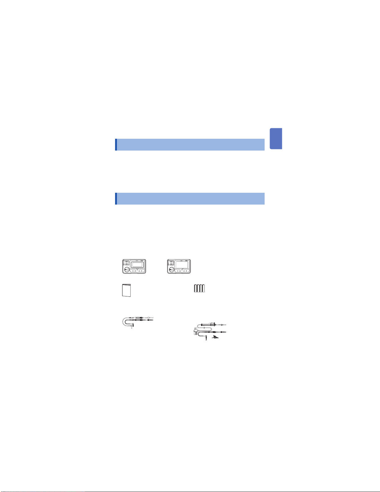
distributor or reseller. Conrm that these contents are provided.
□ Insulation Tester
IR4055, IR4056 IR4057, IR4058
□ Instruction Manual
□ LR6 Alkaline battery × 4
□ Model L9787 Test Lead*
(Only for the instruments with sufx
“-20”)
□ Model L9788-11 Test Lead Set with
Remote Switch*
(Only for the instruments with sufx “-11”
and “-21”)
□ Neck strap
* Model L9787 and L9788-11 are all exclusively designed for the Hioki IR4000
series. Do not use for any other purpose.
1
Find Quality Products Online at: sales@GlobalTestSupply.com
www.GlobalTestSupply.com
Verifying Package Contents
9243 graber
L4937 マグネットアダプ
タ
L4934 小ワニグチ
マグネ付ストラップ
DM4910 熱電対
DT4911TestLead
DT4912TestLead
L4930 接続ケーブル
9243 graber
L4937 マグネットアダプ
タ
L4934 小ワニグチ
マグネ付ストラップ
L9207-10
DM4910 熱電対
DT4911TestLead
DT4912TestLead
L4930 接続ケーブル
L4931renketu
L4931 延長ケーブル
L4932(+9207-10cap)
L4933 コンタクトピン
L4935 ワニ口
L4937 マグネットアダプ
9243 graber
L4937 マグネットアダプ
タ
L4934 小ワニグチ
マグネ付ストラップ
DM4910 熱電対
DT4911TestLead
DT4912TestLead
L4930 接続ケーブル
9243 graber
L4937 マグネットアダプ
タ
L4934 小ワニグチ
マグネ付ストラップ
L9207-10
DM4910 熱電対
DT4911TestLead
DT4912TestLead
L4930 接続ケーブル
L4931renketu
L4931 延長ケーブル
L4932(+9207-10cap)
L4933 コンタクトピン
L4935 ワニ口
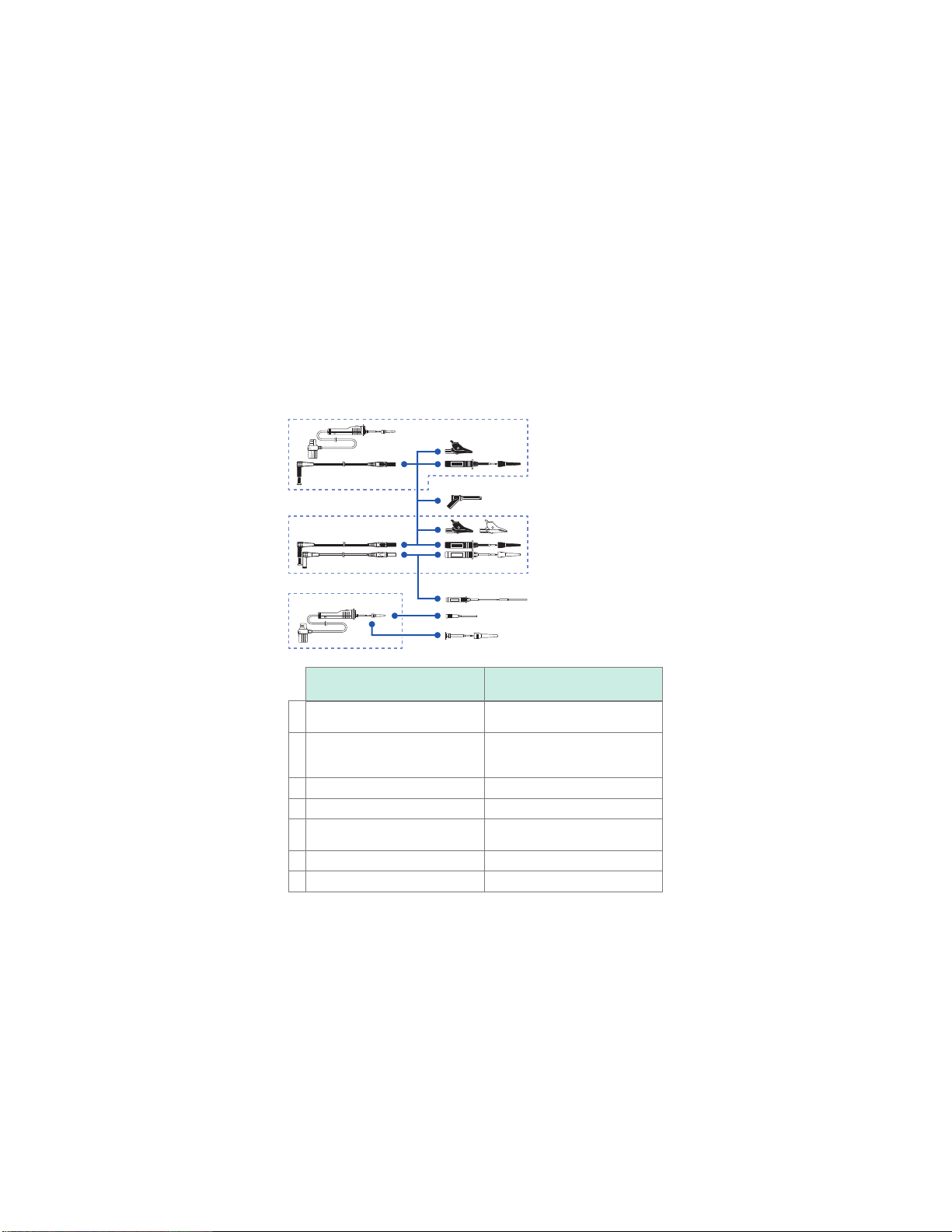
Options
The following options are available for the IR4000 series. Contact
your authorized Hioki distributor or reseller when ordering.
*
1
2
*
3
*
5
6
7
* Refer to p. 1
4
Model
Model L9788-11* Test Lead Set
1
with Remote Switch
Model 9804-02 Magnet Adapter
(φ11 mm, standard screw: M6 pan
2
head screw)
Model L9787* Test Lead (1.2 m) CAT III 600 V/CAT II 600 V, 10 A
3
Model L9787-91 Breaker Pin CAT III 600 V, 10 A
4
Model L9788-10* Test Lead with
5
Remote Switch (Red)
Model L9788-92 Breaker Pin CAT III 600 V, 2 A
6
Model L9788-90 Tip Pin CAT III 600 V/CAT II 600 V, 2 A
7
Find Quality Products Online at: sales@GlobalTestSupply.com
2
www.GlobalTestSupply.com
Maximum rated voltage and
maximum rated current
CAT III 600 V/CAT II 600 V, 2 A
CAT IV 1000 V, 2 A
CAT III 600 V/CAT II 600 V, 2 A
Safety Information
1
2
3
4
5
6
7
付録索引
Safety Information
This instrument is designed to conform to IEC 61010 Safety
Standards, and has been thoroughly tested for safety prior to
shipment. However, using the instrument in a way not described in
this manual may negate the provided safety features.
Before using the instrument, be certain to carefully read the following
safety notes:
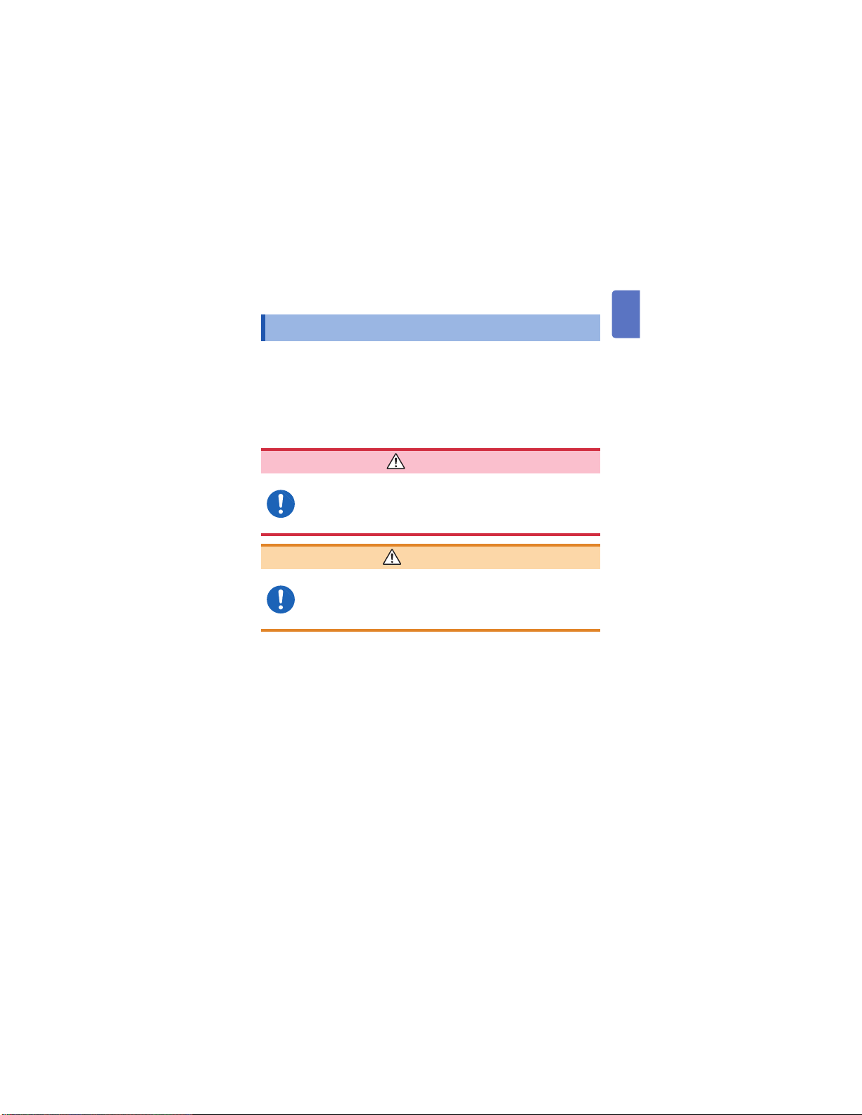
DANGER
Mishandling during use could result in injury or death,
as well as damage to the instrument. Be certain that
you understand the instructions and precautions in
the manual before use.
WARNING
Protective gear
This instrument measures live lines. To prevent
electric shock, use appropriate protective insulation
and adhere to applicable laws and regulations.
3
Find Quality Products Online at: sales@GlobalTestSupply.com
www.GlobalTestSupply.com
Safety Information
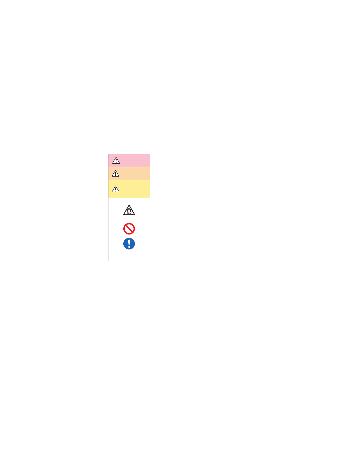
Notation
In this document, the risk seriousness and the hazard levels are
classied as follows.
DANGER
WARNING
CAUTION
Indicates an imminently hazardous situation that will
result in death or serious injury to the operator.
Indicates a potentially hazardous situation that may
result in death or serious injury to the operator.
Indicates a potentially hazardous situation that may
result in minor or moderate injury to the operator or
damage to the instrument or malfunction.
Indicates a strong magnetic- eld hazard.
The effects of the magnetic force can cause
abnormal operation of heart pacemakers and/or
medical electronics.
Indicates prohibited actions.
Indicates the action which must be performed.
*
Additional information is presented below.
4
Find Quality Products Online at: sales@GlobalTestSupply.com
www.GlobalTestSupply.com

Symbols on the instrument
1
2
3
4
5
6
7
付録索引
Indicates cautions and
hazards. When the symbol
is printed on the instrument,
refer to a corresponding
topic in the Instruction
Manual.
Indicates that dangerous
voltage may be present at
this terminal.
Indicates a instrument
that has been protected
throughout by double
insulation or reinforced
insulation.
Symbols for various standards
Indicates the Waste Electrical and Electronic Equipment
Directive (WEEE Directive) in EU member states.
Indicates that the product conforms to regulations set out by the
EU Directive.
Indicates that the product incorporates Bluetooth® wireless
technology.
Safety Information
Indicates a grounding
terminal.
Indicates DC (Direct
Current).
Indicates AC
(Alternating Current).
Do not use in distribution
systems with voltage
higher than 660 V AC.
Screen Display
The instrument screen displays the alphanumeric characters as follows.
A B C D E F G H I J K L M N O P Q R S T U V W X Y Z
1 2 3 4 5 6 7 8 9 0
5
Find Quality Products Online at: sales@GlobalTestSupply.com
www.GlobalTestSupply.com

Safety Information
Accuracy
We dene measurement tolerances in terms of rdg. (reading) and
dgt. (digit) values, with the following meanings:
(reading or displayed value)
rdg.
The value currently being measured and indicated on the
measuring instrument.
(resolution)
The smallest displayable unit on a digital measuring instrument,
dgt.
i.e., the input value that causes the digital display to show a "1" as
the least-signicant digit.
Trademarks
• Bluetooth® is a registered trademark of Bluetooth SIG, Inc. (USA).
The trademark is used by HIOKI E.E. CORPORATION under
license.
• Android and Google Play are trademarks of Google, Inc.
• IOS is a registered trademark of Cisco in the U.S. and other
countries.
• iPhone, iPad, iPad mini, iPad Pro, and iPod Touch are trademarks
of Apple Inc.
• The App Store is a service mark of Apple Inc.
6
Find Quality Products Online at: sales@GlobalTestSupply.com
www.GlobalTestSupply.com
Safety Information
1
2
3
4
5
6
7
付録索引
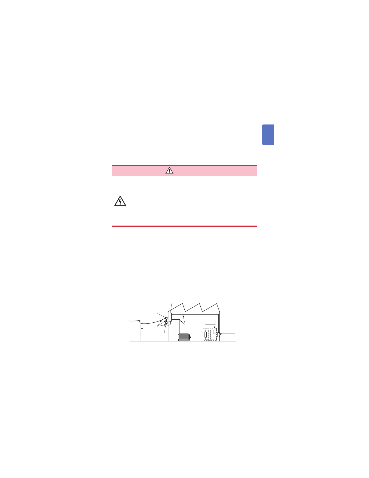
Measurement Categories
To ensure safe operation of measuring instruments, IEC 61010
establishes safety standards for various electrical environments,
categorized as CAT II to CAT IV, and called measurement categories.
DANGER
• Using a measuring instrument in an environment
designated with a higher-numbered category than
that for which the instrument is rated could result in
a severe accident, and must be carefully avoided.
• Never use a measuring instrument that lacks
category labeling in a CAT II to CAT IV measurement
environment. Doing so could result in a serious
accident.
This instrument conforms to the safety requirements for CAT III 600 V
measuring instruments.
CAT II: When directly measuring the electrical outlet receptacles of the
primary electrical circuits in equipment connected to an AC electrical
outlet by a power cord (portable tools, household appliances, etc.)
CAT III: When measuring the primary electrical circuits of heavy equipment
(xed installations) connected directly to the distribution panel, and
feeders from the distribution panel to outlets.
CAT IV:
When measuring the circuit from the service drop to the service
entrance, and to the power meter and primary overcurrent
protection device (distribution panel).
Distribution panel
Service entrance
Service drop
CAT IV
Power meter
Internal wiring
CAT III
Fixed installation
CAT II
T
Outlet
7
Find Quality Products Online at: sales@GlobalTestSupply.com
www.GlobalTestSupply.com
Operating Precautions
Operating Precautions
Follow these precautions to ensure safe operation and to obtain the
full benets of the various functions.
DANGER
• For your safe operation, do not connect any test
lead to the primary of the distribution panel.
• Do not short-circuit two wires to be measured by
bringing the test leads into contact with them. Arcs
or such graveaccidents are likely to occur.
• To avoid short circuit or electric shock, do not touch
the metal part of the connecting test lead tip.
• To avoid electric shock, be careful to avoid shorting
live lines with the test leads tip.
• If the test lead or the instrument is damaged, there
is a risk of electric shock. Perform the following
inspection before using them:
• Before using the instrument check that the coating
of the test leads are neither ripped nor torn and that
no metal parts are exposed. Using the instrument
under such conditions could result in electric
shock. Replace the test leads with those specied
by our company.
• Verify that the instrument operates normally to
ensure that no damage occurred during storage
or shipping. If you nd any damage, contact your
authorized Hioki distributor or reseller.
8
Find Quality Products Online at: sales@GlobalTestSupply.com
www.GlobalTestSupply.com
Operating Precautions
1
2
3
4
5
6
7
付録索引
WARNING
• To avoid electric shock, short circuits and
damage to the instrument, observe the following
precautions:
Check the position of the rotary switch before
taking measurements. Disconnect the test leads
from the measurement object before switching the
rotary switch.
• Do not use the instrument with circuits that exceed
its ratings or specications. Doing so may damage
the instrument, resulting in electric shock.
• Use only the specied test leads. Use of any test
lead not specied by our company does not allow
safe measurements.
• To avoid electrical accidents, remove power from
the circuit before connecting the test leads.
• To avoid electric shock, do not exceed the lower of
the ratings shown on the instrument and test leads.
9
Find Quality Products Online at: sales@GlobalTestSupply.com
www.GlobalTestSupply.com
Operating Precautions
CAUTION
• The cable is hardened under the 0°C or colder
environment. Do not bend or pull it to avoid tearing its
shield or cutting cable.
• The protection rating for the enclosure of this device
(based on EN60529) is IP40*.
* IP40:
This indicates the degree of protection provided by the enclosure of
the device against use in hazardous locations, entry of solid foreign
objects, and the ingress of water.
4: Protected against access to hazardous parts with wire measuring 1.0 mm
in diameter.
0: The equipment inside the enclosure is not protected against the harmful
effects of water.
10
Find Quality Products Online at: sales@GlobalTestSupply.com
www.GlobalTestSupply.com
Installing the instrument
1
2
3
4
5
6
7
付録索引
Installing the instrument in inappropriate locations
may cause a malfunction of instrument or may give
rise to an accident. Avoid the following locations.
• Exposed to direct sunlight or high temperature
• Exposed to corrosive or combustible gases
• Exposed to a strong electromagnetic eld or
electrostatic charge
• Near induction heating systems (such as high-
frequency induction heating systems and IH
cooking equipment)
• Susceptible to vibration
• Exposed to water, oil, chemicals, or solvents
• Exposed to high humidity or condensation
• Exposed to high quantities of dust particles
Do not place the instrument on an unstable table or an
inclined place. Dropping or knocking down the instrument
can cause injury or damage to the instrument.
Operating Precautions
WARNING
CAUTION
Precautions when transporting the instrument
During shipment of the instrument, handle it carefully so that it is not
damaged due to a vibration or shock.
11
Find Quality Products Online at: sales@GlobalTestSupply.com
www.GlobalTestSupply.com
Operating Precautions
Handling the Instrument
Persons wearing electronic medical devices such as
apacemaker should not use model 9804-02 Magnet
Adapter. Such persons should avoid even proximity
to model 9804-02, as it may be dangerous. Medical
device operation could be compromised, presenting a
hazard to human life.
To avoid damage to the instrument, protect it from physical
shock when transporting and handling. Be especially
careful to avoid physical shock from dropping.
Test leads
• Removable sleeves are attached to the metal pins
at the end of the test leads. To prevent a short circuit
accident, be sure to use the test leads with the sleeves
attached when performing measurements in the CAT
III measurement category. Remove the sleeves before
starting CAT II measurements. You can use the test
leads with the sleeve removed for primary side of
the circuit breakers turned off. (See “Measurement
Categories” (p. 7))
• If the sleeves are inadvertently removed during
measurement, stop the measurement. (p. 1)
DANGER
CAUTION
CAUTION
12
Find Quality Products Online at: sales@GlobalTestSupply.com
www.GlobalTestSupply.com

1 Overview
1
2
3
4
5
6
7
付録索引
Overview
1
1.1 Product Overview
This instrument is an insulation ohmmeter that shortens work times
associated with insulation testing. It is not designed for use on
manufacturing lines and should not be used in such applications.
For manufacturing line applications, use the model ST5520
Insulation Tester.
High-speed response
• Considerably improved response time compared to previous models.
• The instrument can be used like models with a meter needle.
Enhanced comparator function
• Can be used similarly to the continuity check with a tester due to judgment
after the start of measurement being extremely short.
• The backlight lights up in red for a FAIL judgment (defective).
Low variation in measured values
• The instrument generates little variation in measured values when used in a
typical measuring environment.
Easy-to-view display
• Backlight source is a white high-intensity LED.
• Wide viewing angle LCD
High-accuracy voltage measurement function
• The instrument incorporates a DC/AC voltmeter with the same accuracy as
a card tester.
• There is no need to switch to a card tester when you need to measure
voltage.
PVΩ measurement function (Model IR4055)
• Insulation resistance can be measured accurately for solar battery panel.
13
Find Quality Products Online at: sales@GlobalTestSupply.com
www.GlobalTestSupply.com
Names and Functions of Parts
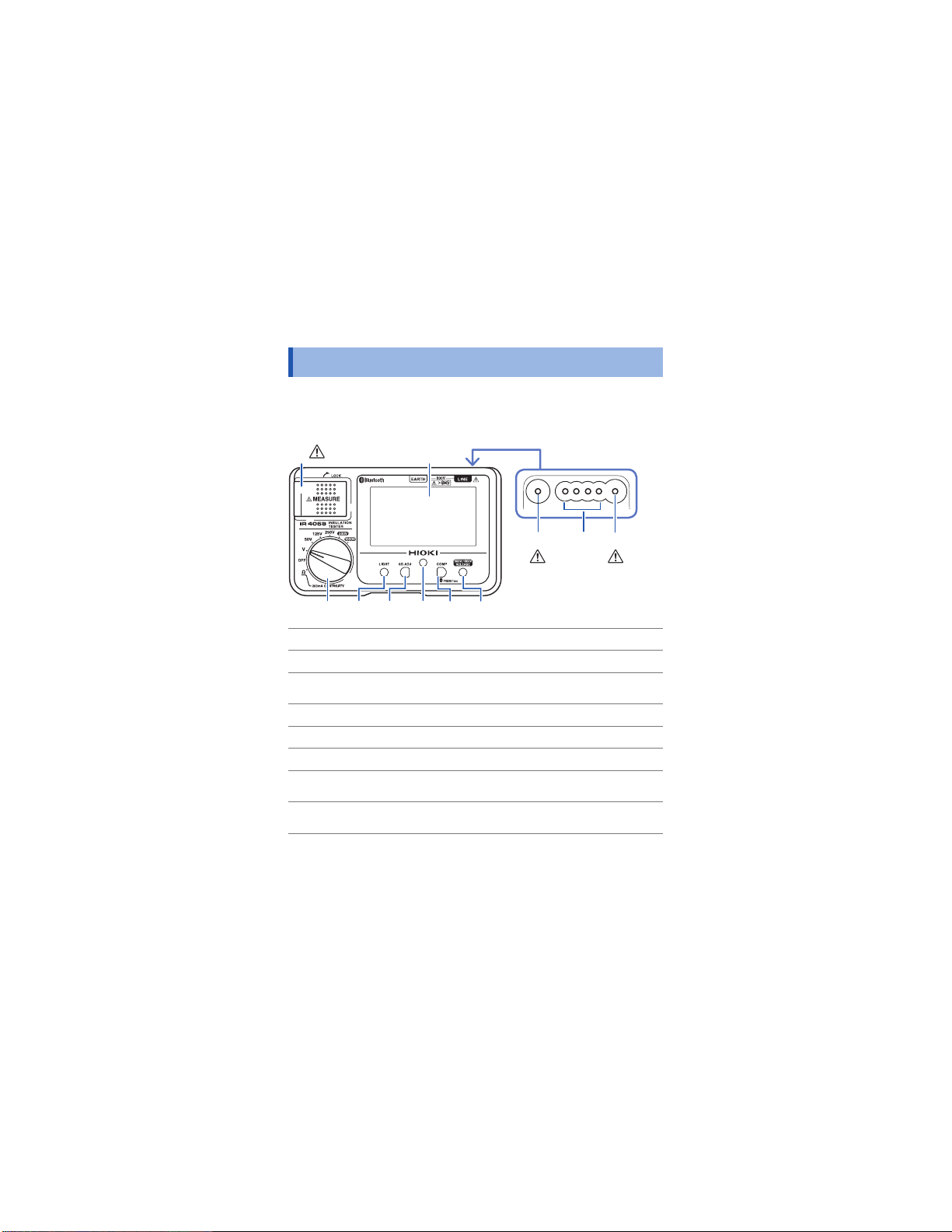
1.2 Names and Functions of Parts
Front
IR4056, IR4057, IR4058
(p. 19, p. 22,
p. 32, p. 38)
1
(The gure below is model IR4058)
Display
Top
32
4
(p. 8)
1065 97 8
MEASURE key (p. 16) Starts insulation resistance measurement.
1
Earth terminal Connects the black test lead.
2
Control terminal
3
Line terminal Connects the red test lead.
4
Rotary switch Selects measurement functions.
5
LIGHT key
6
0Ω ADJ key
7
Live circuit indicator
8
Controls model L9788-10 Test Lead with
Remote Switch (Red)
Turns on and off the light.
Performs zero-adjustment for the low
resistance range.
Lights up when voltage remains between
input terminals.
14
(p. 8)
Find Quality Products Online at: sales@GlobalTestSupply.com
www.GlobalTestSupply.com
Names and Functions of Parts
1
2
3
4
5
6
7
付録索引
COMP key
9
Bluetooth key
RELEASE key
10
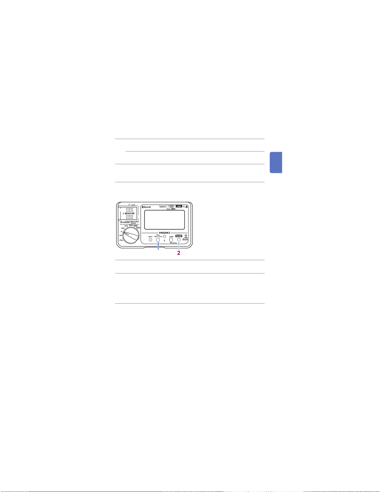
IR4055
500 V↔1000 V key
1
500 V/1000 V
2
RELEASE key
Sets the comparator’s judgment reference
value.
Sets the Bluetooth
(IR4055, IR4058)
Press before measurement to set the instrument
to the 500 V or 1000 V range (to prevent
erroneous application of the test signal).
1 2
Switches between 500 V and 1000 V when using
PV
range.
Ω
• Press before measurement to set the instrument
to the 500 V or 1000 V range (to prevent
erroneous application of the test signal).
• Applied voltage is conrmed when PVΩ range
is set.
®
(p. 49)
(Other functions are the same as
IR4056, IR4057, and IR4058.)
15
Find Quality Products Online at: sales@GlobalTestSupply.com
www.GlobalTestSupply.com
Names and Functions of Parts
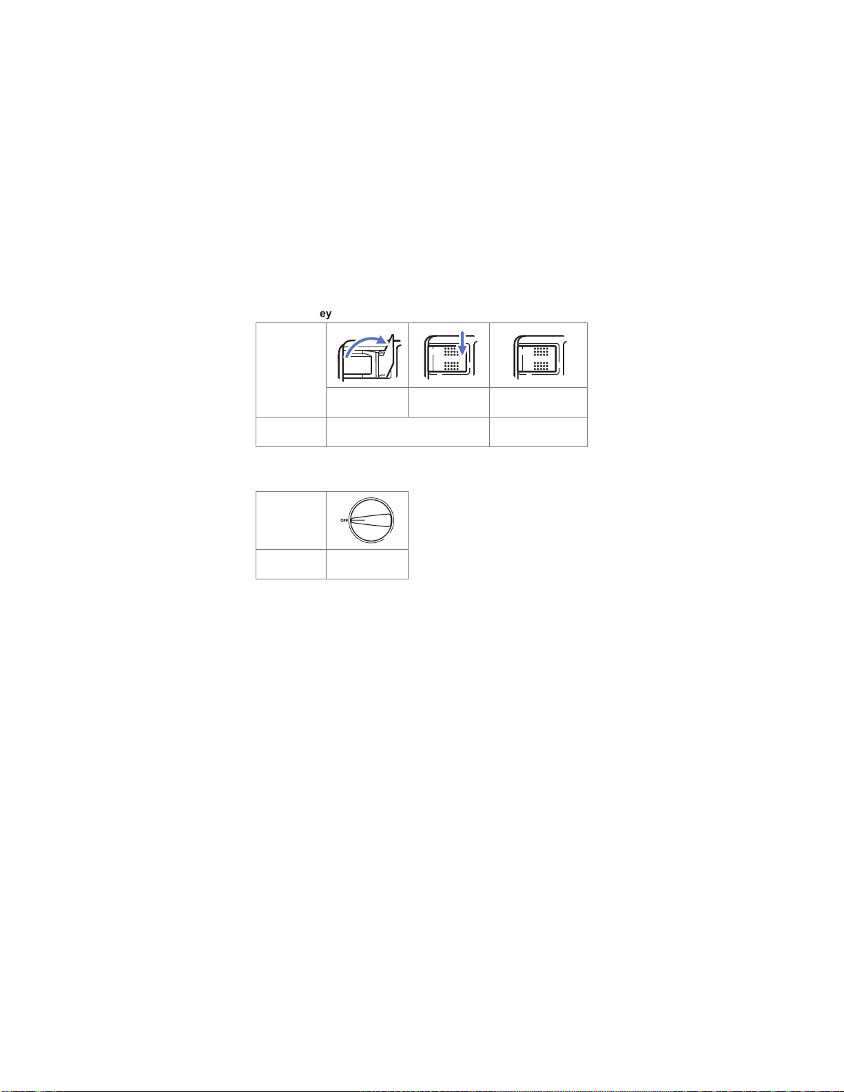
MEASURE key
MEASURE key
states
*
Pull
Description in
this manual
*: Convenient way for performing measurement repeatedly
Turn on the MEASURE key.
Press the right
portion
Power OFF
Rotary switch
state
Release
Turn off the
MEASURE key.
Description in
this manual
16
Turn off the rotary
switch.
Find Quality Products Online at: sales@GlobalTestSupply.com
www.GlobalTestSupply.com
Display
1
2
3
4
5
6
7
付録索引
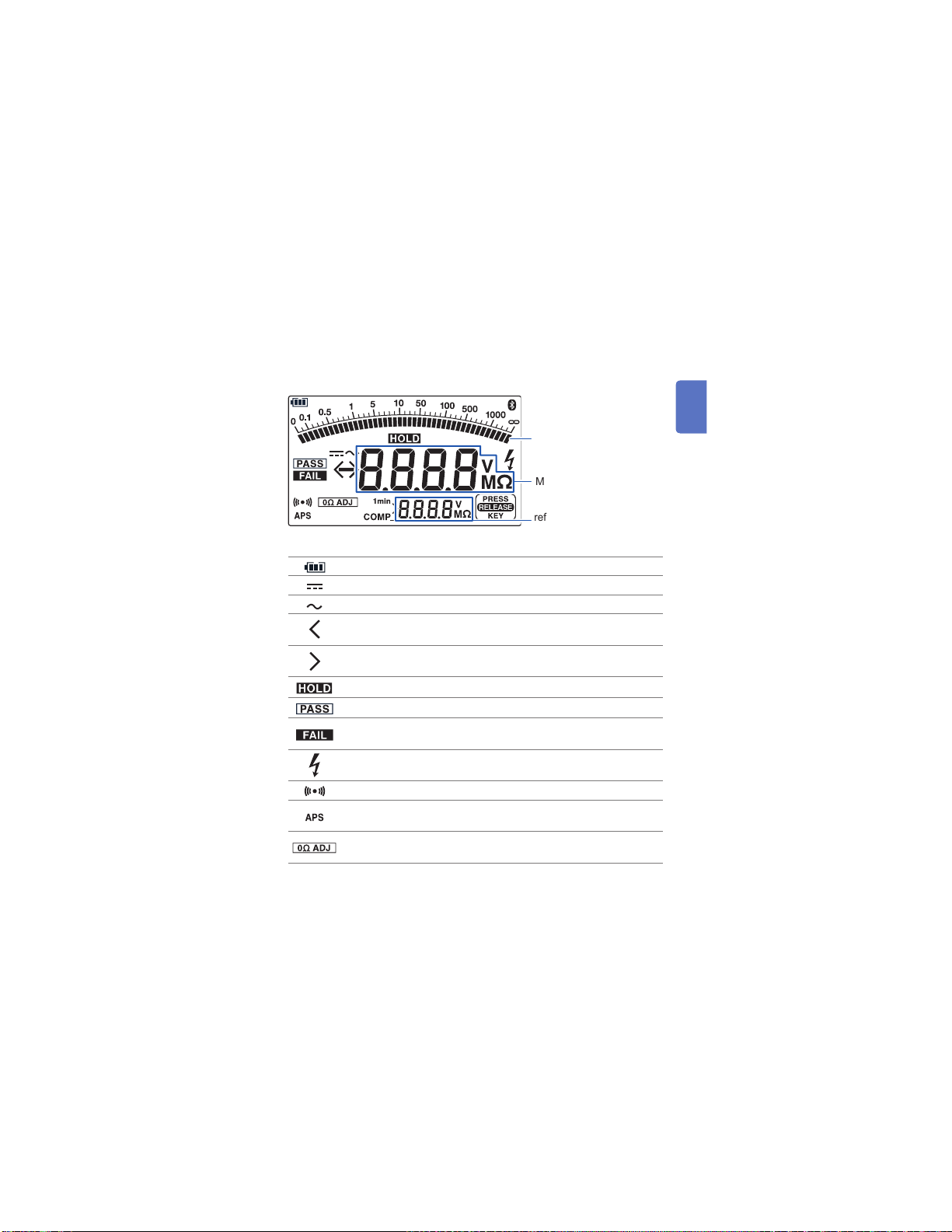
IR4057, IR4058
Battery indicator (three levels) (p. 27)
Turns on when the voltage measured with the V range is DC.
Turns on when the voltage measured with the V range is AC.
Blinks when the measured value is less than the minimum display
value.
Blinks when the measured value is greater than the maximum
display value.
Turns on when the measured value is retained.
Turns on when the comparator judgment is PASS (good). (p. 29)
Turns on when the comparator judgment is FAIL (defective).
(p. 29)
Blinks when a dangerous voltage exists between the
measurement terminals.
Judgment result buzzer (only when comparator is set) (p. 29)
The auto power save function will activate 30 seconds after this
mark starts turning on. (p. 28)
Turns on when zero adjustment is made during low resistance
measurement. (p. 40)
Names and Functions of Parts
(The gure below is model IR4058)
Bar graph
Measured value
Comparator judgment
reference value or 1-minute
value
17
Find Quality Products Online at: sales@GlobalTestSupply.com
www.GlobalTestSupply.com
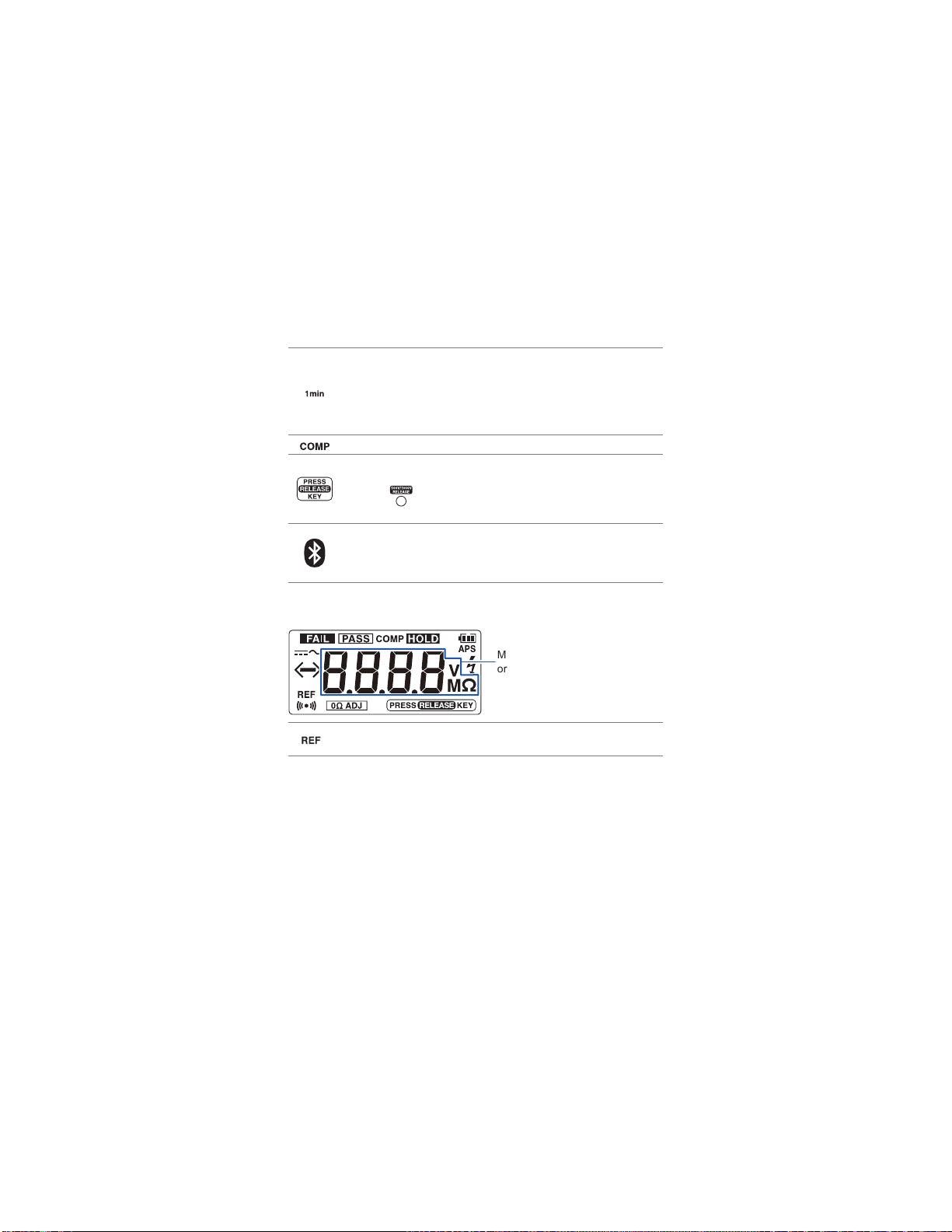
Names and Functions of Parts
Displaying 1-minute values (p. 35)
• Turns on when 1 minute has passed since the start of insulation
resistance measurement.
• Indicates that the resistance value on the bottom of the display
is a 1-minute value (the measured value 1 minute after the start
of measurement).
Turns on when the comparator function is enabled. (p. 29)
Turns on when the instrument is set to the 500 V range or the
1000 V range.
Pressing
measurement.
Displays Bluetooth® function state.
• Bluetooth
• Bluetooth
• Bluetooth
turns off the indicator and enables insulation
®
function ON: Turns on
®
function OFF: Turns off
®
Communicating: Blinks
IR4056
Turns on when the reference value is indicated by the
comparator function.
Measured value
or comparator reference value
(Other functions are the same as
IR4057 and IR4058.)
18
Find Quality Products Online at: sales@GlobalTestSupply.com
www.GlobalTestSupply.com
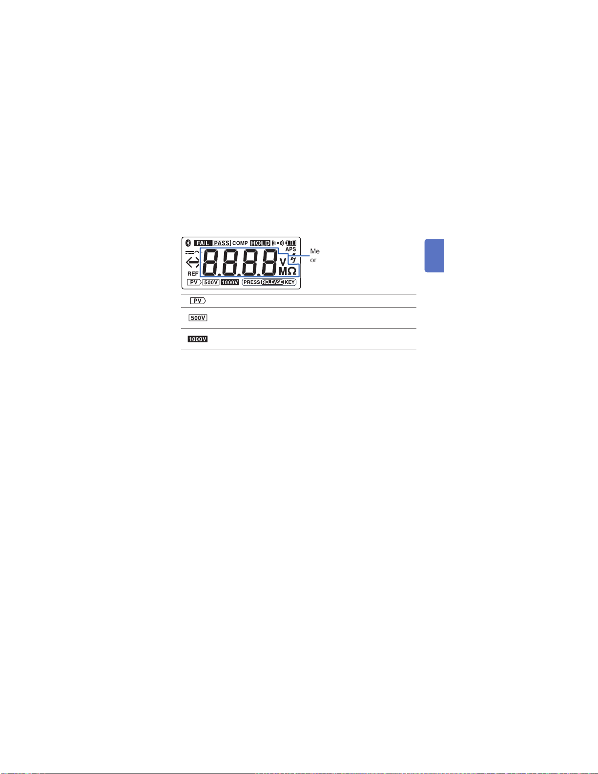
IR4055
1
2
3
4
5
6
7
付録索引
Names and Functions of Parts
Measured value
or comparator reference value
(Other functions are the same as
IR4056, IR4057, and IR4058.)
Turns on when PVΩ measurement mode is selected.
Turns on when selecting 500 V range in the PVΩ measurement
mode.
Turns on when selecting 1000 V range in the PVΩ measurement
mode.
19
Find Quality Products Online at: sales@GlobalTestSupply.com
www.GlobalTestSupply.com
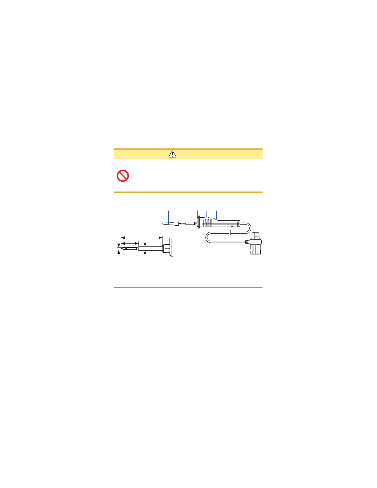
Names and Functions of Parts
Model L9788-10 Test Lead with Remote Switch (Red)
CAUTION
The MEASURE key of the instrument is enabled even
when the L9788-10 is connected to an insulation
resistance tester. Note that the testing voltage is output
when the MEASURE key of the instrument is turned ON
while the L9788-10 is connected.
Refer to “Attaching the L9788-92 Breaker Pin” (p. 26)
Sleeve
Enlarged tip view
35
16
1 2 3
Plug
1.8
φ
Light
1
MEASURE key
2
Judgment display
3
20
3.0
φ
Unit: mm
Lights up interlocked with the backlight of the
instrument.
• Starts insulation resistance measurement.
• Lights up in red interlocked with the live wire
warning indicator of the instrument.
Lights up in accordance with the comparator
judgment result.
• PASS: Green
• FAIL: Red
Find Quality Products Online at: sales@GlobalTestSupply.com
www.GlobalTestSupply.com
 Loading...