

Hioki IR4053 User Manual
Insulation Tester IR4053
Takeaki Miyazawa
Engineering Division 5, Engineering Department
Abstract—The Insulation Tester IR4053 is an insulation
tester designed for use in the maintenance of solar power
system equipment. This paper describes the product’s features,
architecture, and other characteristics.
I. IntroductIon
Due in part to rising awareness of environmental issues,
increasingly serious power shortages, and Japan’s national
initiatives to promote use of solar power in recent years,
there has been rapid growth in use of solar power systems,
from small-scale residential setups to large-scale megasolar
installations. These developments are driving growing
demand for equipment maintenance.
1
Insulation Tester IR4053
To prevent accidents caused by faulty insulation during
installation and regular inspections of solar power systems,
it is necessary to check the state of insulation by measuring
the insulation resistance at various points in the system.
When using a standard insulation tester to accomplish this
task, the technician must cut off power to the measurement
target before measuring the insulation resistance. In the
case of solar panels, insulation resistance must be measured
while the system is at a dangerous voltage since electricity
is always generated while the system is exposed to sunlight
during the day. Consequently, technicians must exercise a
high level of caution with regard to the hazard of electrical
shock while measuring insulation resistance. In addition,
it is sometimes not possible to obtain accurate resistance
insulation values when a standard insulation tester is used
to test a solar power system because the voltage produced by
the solar panels affects the measurement results.
It was against this backdrop that Hioki developed the
Insulation Tester IR4053 as an instrument that is able to
safely and accurately measure the insulation resistance of
solar panels.
II. overvIew
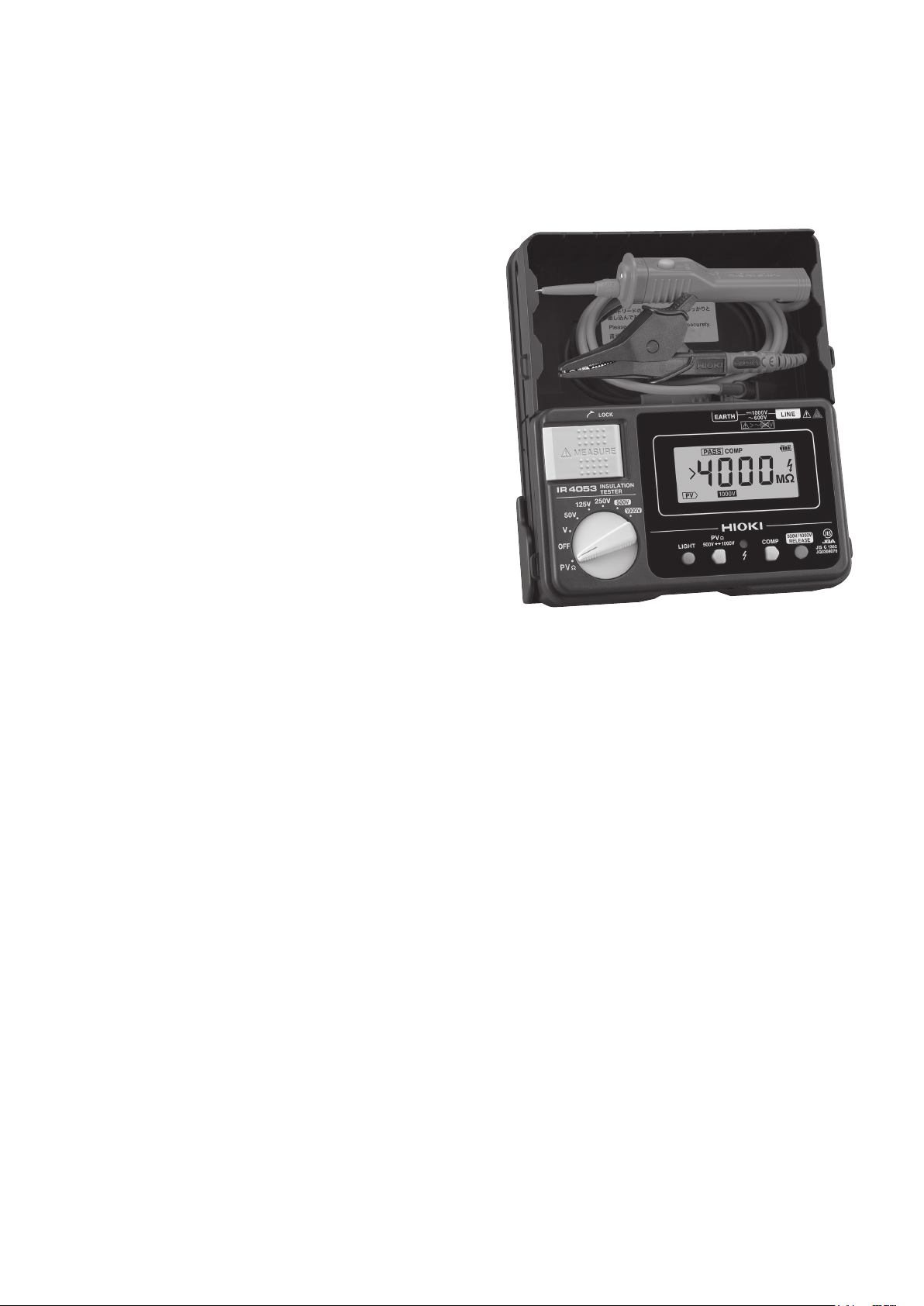
A. Overview of the IR4053
The IR4053 is a portable digital insulation tester.
Developed to be capable of measuring the insulation
resistance of solar panels safely, accurately, and quickly, it is
ideal for maintenance of solar power systems.
The instrument features a new photovoltaic resistance
function designed specically to measure the insulation
resistance of solar panels. This function makes it possible
to accurately measure insulation resistance free from the
effects of the electricity being produced by the panel under
Appearance of the IR4053.
measurement. Furthermore, the instrument provides voltage
measurement functionality for measuring voltages of up to
1000 V DC, a capability that is ideal for measuring the noload voltage of solar panels.
In addition, the instrument provides ordinary insulation
resistance measurement functionality (with ve ranges)
that complies with Japanese Industrial Standards (JIS)
C1302, allowing measurement of the insulation resistance
of equipment other than solar panels.
The IR4053 is available in two congurations: as the
IR4053-10, which includes standard-type test leads, and as
the IR4053-11, which includes switched test leads, for the
Japanese domestic market.
B. Measurement of Solar Panel Insulation Resistance
The technical report JEM-TR228, Maintenance and
inspection guidelines for photovoltaic power generating
systems up to 50 kW for low-voltage network (Japanese),
published by The Japan Electrical Manufactures’
Association, provides important information about the
maintenance and inspection of solar power systems. The
guidelines describe the measurement methods in addition
to the maintenance and inspection items of small-scale solar
power systems, and they recommend that the insulation
resistance of relay terminal boxes (junction boxes and power
HIOKI Technical Notes Vol. 2 2016 No. 1
2
LINE: −
EARTH: +
Positive terminal
Negative terminal
Insulation
resistance
tester
Bypass diode
Blocking device
Earth
LINE: −
EARTH: +
Insulation
resistance
tester
Shorting switch
Earth
Insulation Tester IR4053
collection boxes) and power conditioning systems (PCSs) be
measured as part of both the post-installation inspection and
regular inspections.
Two methods are used to measure the insulation
resistance of solar panels, and they differ in both safety
and accuracy. Whichever method is used, all strings must
be measured. To prepare for measurement, the junction
box’s output disconnect must be turned off to isolate it from
the PCS and power collection box. In addition, all string
switches must be turned off. Each of the two methods is
described below.
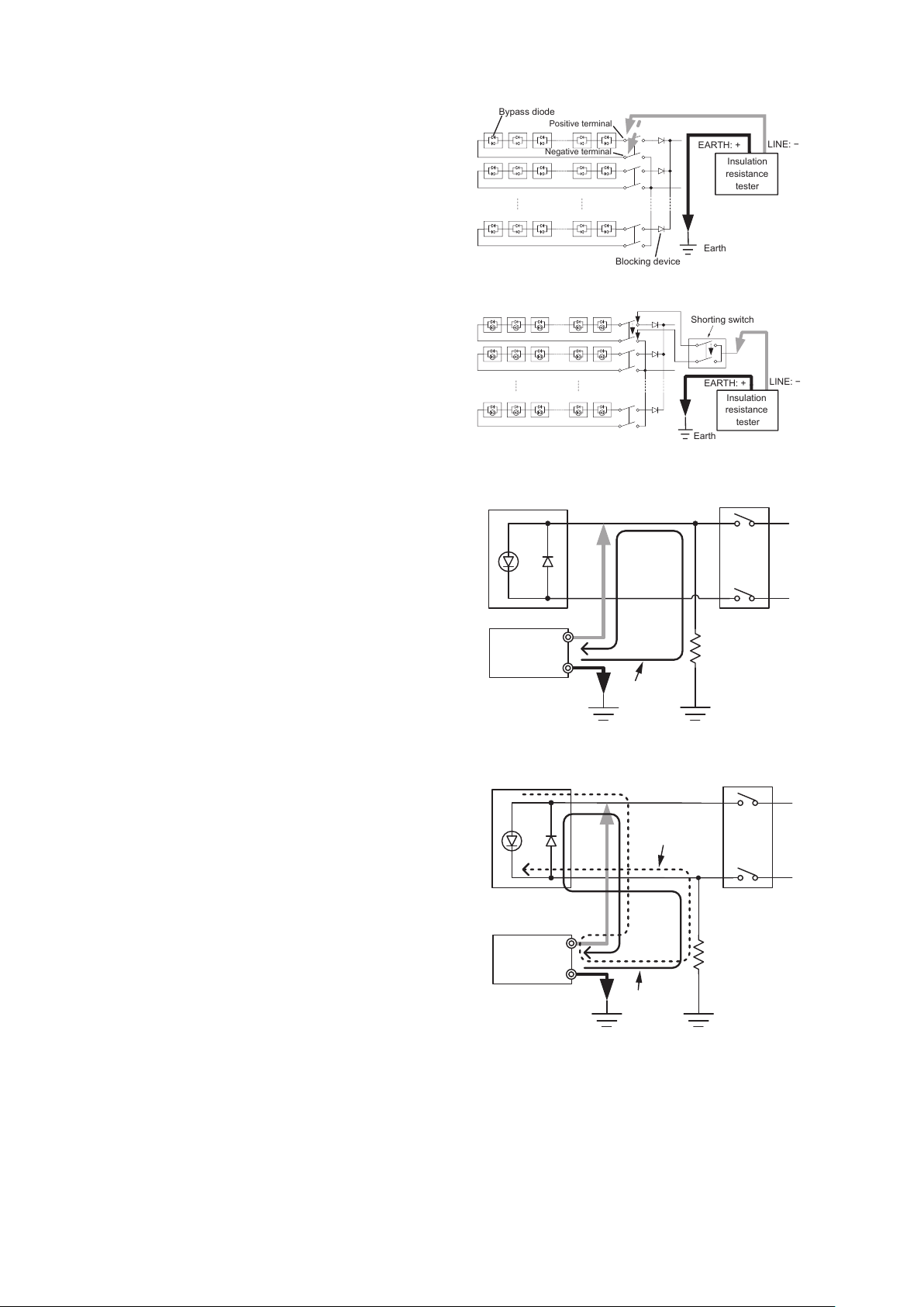
1) Method in which P and N are not short-circuited:
Fig. 1 illustrates a measurement method in which P (the
positive electrode) and N (the negative electrode) are not
short-circuited. The insulation resistance between P and
E (ground) is measured, and then the insulation resistance
between N and E is measured. This method is safer than
the method in which P and N are short-circuited, which is
described below. However, in some cases it is not possible
to obtain an accurate insulation resistance value due to
the effect of the voltage produced by the solar cell on
insulation resistance measurement, which results from the
deterioration of the solar panel’s insulation.
Fig. 1. Method in which P and N are not short-circuited.
Fig. 2. Method in which P and N are short-circuited.
PV string
For cutoff of solar strings
P
2) Method in which P and N are short-circuited: Fig.
2 illustrates a measurement method in which P and N are
short-circuited. A shorting switch is used to short-circuit P
and N, and the insulation resistance between the output of
the shorting switch and E is measured. While this method
yields accurate insulation resistance values, it poses the risk
of daytime electric shock, since that’s when solar panels
operate. In this way, an arc discharge could occur during
work. In addition, abnormal heating may occur when P
and N terminals of a faulty solar panel are short-circuited,
Insulation
resistance
tester
EARTH
LINE
Earth
Measured
current
Resistance
(ground fault)
Earth
N
posing a re hazard.
3) Example of the failure of the non-short-circuiting
method to yield accurate measurements: Fig. 3 and Fig. 4
illustrate measurement of the insulation resistance between
P and E when the P terminal is grounded and when the N
Fig. 3. P-E measu rement diagram when P is grounded.
PV string
For cutoff of solar strings
P
terminal is grounded, respectively.
When measuring the insulation resistance between P
PV current
and E while the P terminal is grounded, as shown in Fig.
3, there is no route by which current produced by the solar
N
panel can nd its way to the insulation tester, enabling
accurate measurement. However, when measuring the
circuit with the N terminal grounded, as shown in Fig. 4,
current produced by the solar panel can ow to the insulation
resistance
tester. Since current from the instrument and current from
the solar panel ow in the same direction and are added, the
result is that the measured resistance value is less than the
actual insulation resistance. By contrast, if the instrument
is connected such that the direction of the insulation tester’s
current is opposite to that of the solar panel’s current,
the current values are subtracted, with the result that the
Fig. 4. P-E measu rement diagram when N is grounded.
Insulation
tester
EARTH
LINE
Earth
Measured
current
Resistance
(ground fault)
Earth
indicated measured resistance value is larger than the actual
HIOKI Technical Notes Vol. 2 2016 No. 1
 Loading...