

Hioki IR4056, IR4057, IR4051, IR4053, IR4052 Instruction Manual

IR4056
IR4057
Instruction Manual
INSULATIONTESTER
July 2015 Revised edition 3
IR4056A981-03 15-07H
EN


i
Contents
Contents
Introduction ...............................................................1
Verifying Package Contents......................................1
Options......................................................................2
Safety Information.....................................................3
Operating Precautions..............................................6
Chapter 1 Overview 9
1.1 Product Overview........................................9
1.2 Features......................................................9
1.3 Names and Functions of Parts..................10
Chapter 2 Measurement Procedures 13
2.1 Measurement Preparations.......................13
2.2 Pre-measurement inspection ....................14
2.3 Configuring the Comparator......................15
2.3.1 Setting the Comparator..................16
2.3.2 Canceling the Comparator.............16
2.4 Insulation Resistance Measurement.........18
2.4.1 Lock Function.................................19
2.4.2 Measuring Insulation Resistance...21
2.4.3 Displaying 1-min. Values
(IR4057 Function) ..........................22
2.5 Discharging Function.................................23
IR4056A981-03

ii
Contents
2.6 Voltage Measurement............................... 24
2.7 Low Resistance Measurement.................. 26
2.8 Auto power save
(power-saving function)............................. 28
2.9 Auto-backlight-off......................................28
Chapter 3 Specifications 29
Standard Specifications ....................................29
General Specifications ...................................... 30
Measurement functions ........................... ... ... ... .31
Chapter 4 Maintenance and Service 37
4.1 Troubleshooting........................................37
4.2 Replacing Batteries or Fuse......................41
4.3 Cleaning....................................................42
Appendix 43
1
Introduction
Introduction
Thank you for purchasing the HIOKI Model IR4056, IR4057
Insulation Tester. To obtain maximum performance from the
instrument, please read this manual first, and keep it handy for
future reference.
The “instrument” in this manual means IR4056 or IR4057.
Verifying Package Contents
• When you receive the instrument, inspect it carefully to ensure
that no damage occurred during shipping. If damage is
evident, or if it fails to operate according to the specifications,
contact your authorized Hioki distributor or reseller.
• When transporting the instrument, use the original packing
materials in which it was shipped, and pack in a double carton.
Damage occurring during transportation is not covered by
warranty.
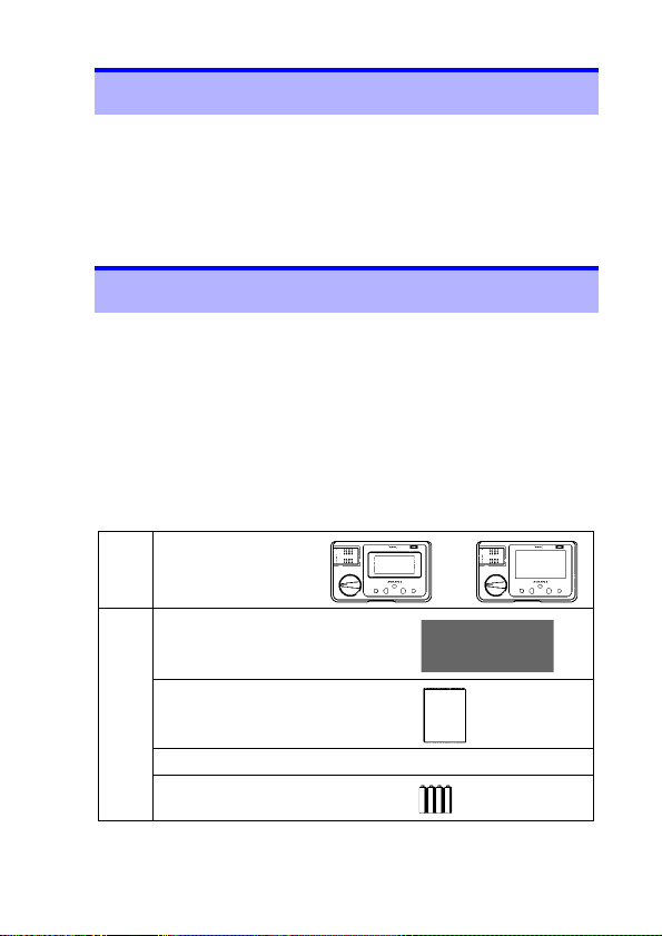
Package Contents
IR4056, IR4057
Insulation Tester
Name
Model
L9787 Test Lead *
Instruction manual............1
Accessories
Neck strap........................ 1
LR6 alkaline battery ......... 4
............ 1
1
2
3
4
5
6
7
8
9
10
索引
* L9787 Test Lead is exclusively designed for the HIOKI IR4000
series. Do not use for any other purpose.
2
Options
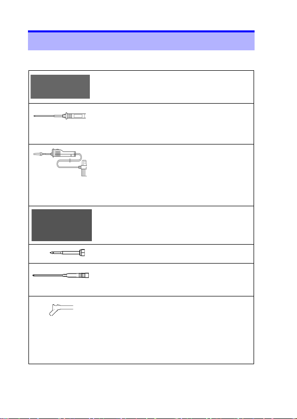
Options
The following options are available for the IR4000 series. Ask
your authorized Hioki distributor or reseller when ordering.
□ L9787 Test Lead * (1.2 m)
□ L9787-91 Breaker Pin
(Pin length 70 mm and 48 mm from the tip has
width 2.5 mm. The rest have width 3.8 mm.)
Breaker pin for model L9787.
□ L9788-10 Test Lead with Remote Switch
Test lead with MEASURE key for the line side
measurement. Measurement can be started by
pressing the key. There is a light at the tip which
can be switched on by pressing the LIGHT key
on the IR4000 Series. Earth side lead is not
attached.
□ L9788-11 Test Lead Set with Remote
Set of the model L9788-10 and L9787 with an
EARTH side lead.
□ L9788-90 Tip Pin
Replacement Tip Pin for model L9788-10.
□ L9788-92 Breaker Pin
(Pin length 123 mm and 65 mm from the tip has
width 2.6 mm.)
Breaker pin for model L9788-10.
□ 9804-02 Magnetic Adapter
(Ø11 mm Corresponding standard screw: M6
Button head screw)
Adaptor for connecting a Test lead to the round
head screw by means of magnetism. The tip of
adaptor is a concave shape in order to fit the
round head screw. Put an adaptor on the tip of
the earth side lead of a L9787 Test Lead or
L9788-01 Complete Test Lead.
* L9787 Test Lead, L9788-10 Test Lead with Remote Switch (Red) and
L9788-11 Test Lead Set with Remote Switch are all exclusively designed
for the HIOKI IR4000 series. Do not use for any other purpose.
(Red) * (1.2 m)
Switch *
3
Safety Information
Safety Information
1
This instrument is designed to comply with IEC 61010
Safety Standards, and has been thoroughly tested for
safety prior to shipment. However, mishandling during
use could result in injury or death, as well as damage to
the instrument. Using the instrument in a way not
described in this manual may negate the provided safety
features. Be certain that you understand the instructions
and precautions in the manual before use. We disclaim
any responsibility for accidents or injuries not resulting
directly from instrument defects.
Safety Symbols
This manual contains information and warnings essential for
safe operation of the instrument and for maintaining it in safe
operating condition. Before using it, be sure to carefully read the
following safety precautions.
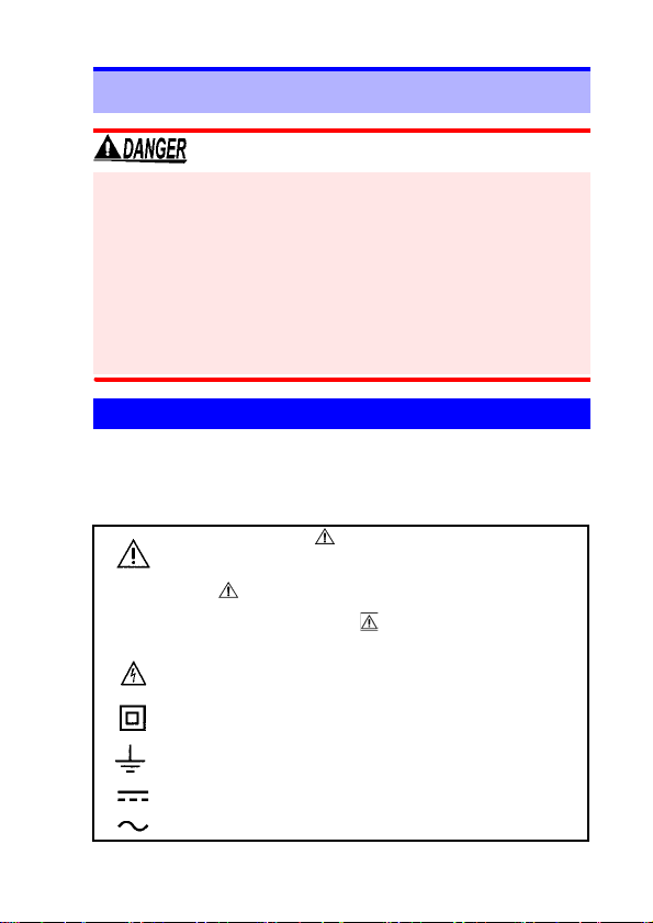
In the manual, the symbol indicates particularly
important information that the user should read before
using the instrument.
The symbol printed on the instrument indicates that
the user should refer to a corresponding topic in the
manual (marked with the symbol) before using the
relevant function.
Indicates that dangerous voltage may be present at this
terminal.
Indicates a double-insulated device.
Indicates a grounding terminal.
Indicates DC (Direct Current).
Indicates AC (Alternating Current).
2
3
4
5
6
7
8
9
10
索引
4
Safety Information
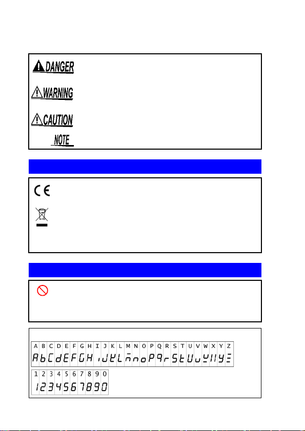
The following symbols in this manual indicate the relative importance of cautions and warnings.
Indicates that incorrect operation presents an extreme
hazard that could result in serious injury or death to the
user.
Indicates that incorrect operation presents a significant
hazard that could result in serious injury or death to the
user.
Indicates that incorrect operation presents a possibility
of injury to the user or damage to the instrument.
Indicates advisory items related to performance or
correct operation of the instrument.
Symbols for Various Standards
This symbol indicates that the product conforms to regulations
set out by the EC Directive.
WEEE marking:
This symbol indicates that the electrical and electronic
appliance is put on the EU market after August 13 , 2005, and
producers of the Member States are required to display it on
the appliance under Article 11.2 of Directive 2002/96/EC
(WEEE).
Other Symbols
Indicates a prohibited action.
Indicates the location of reference information.
(p. )
Indicates that descriptive information is provided below.
*
The screen of this instrument displays characters in the following manner.
5
Safety Information
Accuracy
We define measurement tolerances in terms of rdg. (reading)
and dgt. (digit) values, with the following meanings:
rdg. (reading or displayed value)
The value currently being measured and indicated on the
measuring instrument.
rdg. (reading or displayed value)
The smallest displayable unit on a digital measuring instrument,
i.e., the input value that causes the digital display to show a "1"
as the least-significant digit.
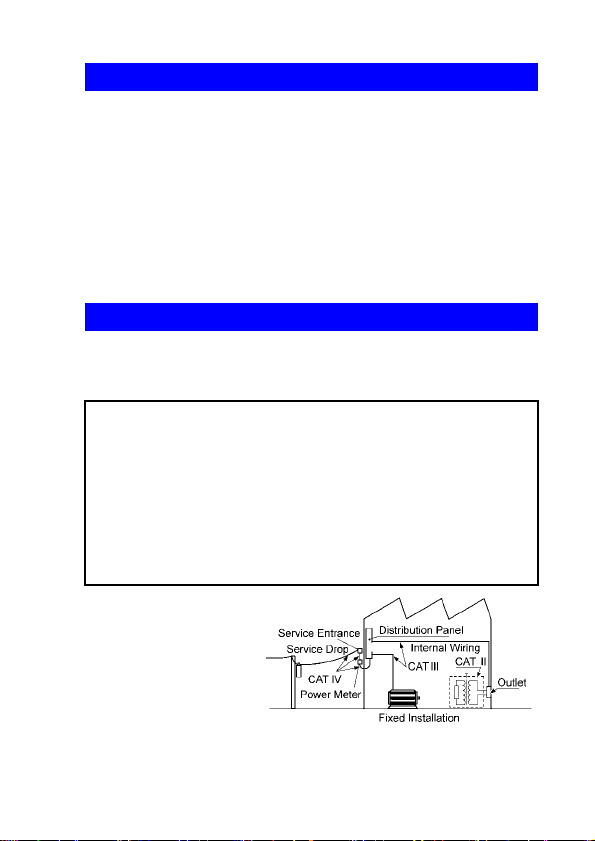
Measurement categories
This instrument complies with CAT III safety requirements.
To ensure safe operation of measurement instruments, IEC 61 010
establishes safety standards for various electrical environments,
categorized as CAT II to CAT IV, and called measurement categories.
Primary electrical circuits in equipment connected to an AC
CAT II:
CAT III:
CAT IV:
Using a measurement
instrument in an
environment designated
with a higher-numbered
category than that for
which the instrument is
rated could result in a
severe accident, and must
be carefully avoided.
Use of a measurement
instrument that is not
CAT-rated in CAT II to CAT IV measurement applications could result in a
severe accident, and must be carefully avoided.
electrical outlet by a power cord (portable tools, household
appliances, etc.)
CAT II covers directly measuring electrical outlet
receptacles.
Primary electrical circuits of heavy equipment (fixed
installations) connected directly to the distribution panel,
and feeders from the distribution panel to outlet s.
The circuit from the service drop to the service entrance,
and to the power meter and primary overcurrent protection
device (distribution panel).
1
2
3
4
5
6
7
8
9
10
索引

6
Operating Precautions
Operating Precautions
Follow these precautions to ensure safe operation and to obtain
the full benefits of the various functions.
Preliminary Checks
Before using the instrument for the first time, verify that it operates normally to ensure that no damage occurred during storage
or shipping. If you find any damage, contact your authorized
Hioki distributor or reseller.
To prevent an electric shock accident, confirm that the
white or red portion (insulation layer) inside the cable is
not exposed. If a color inside the cable is exposed, do not
use the cable.
Setting up the Instrument
Operating temperature and humidity (p.30)
Accuracy guarantee for temperature and humidity (p.31)
Avoid the following locations that could cause an accident or damage to
the instrument.
Exposed to direct
sunlight
Exposed to high
temperature
Exposed to water,
oil, other chemicals,
or solvents
Exposed to high
humidity or
condensation
Exposed to high
levels of particulate
dust
Subject to vibration
In the presence of
corrosive or explosive
gases
Exposed to strong
electromagnetic fields
Near electromagnetic
radiators
Near induction heating
systems
(e.g., high-frequency
induction heating
systems and IH cooking
utensils)
7
Operating Precautions
• The maximum rated voltage between input terminals
and ground is 600 V DC/AC (CAT III). Attempting to
measure voltages exceeding 600 V DC/AC with
respect to ground could damage the instrument and
result in personal injury.
• 1000 V or 600 V may be labeled depending on the
supplied test leads, but this is the rating of the test lead
and not the rating performance of this instrument.
Please refer to the Specifications for the rating
performance of this instrument.
• Before attaching to or removing the test lead from the
instrument, please remove the Test Lead from the
tested objected and turn the rotary selector to OFF.
• Test leads should only be connected to the secondary
side of a breaker, so the breaker can prevent an
accident if a short circuit occurs. Connections should
never be made to the primary side of a breaker,
because unrestricted current flow could cause a
serious accident if a short circuit occurs.
• Persons wearing electronic medical devices such as a
pacemaker should not use the 9804-02 Magnetic
Adapter with magnet (option). Such persons should
avoid even proximity to the 9804-02, as it may be
dangerous. Medical device operation could be
compromised, presenting a hazard to human life.
1
2
3
4
5
6
7
8
9
Please only use batteries for electrical supply. Any other
electrical supply may damage the instrument and tested
object and cause electric shock.
10
索引

8
Operating Precautions
• If the 9804-02 is brought near a magnetic memory device
such as a floppy disk, credit/debit card, or pre-paid card or
ticket, the device may become unusable due to data
corruption. It can also cause damage if brought near a
precision electronic device such as a computer, TV, or
electronic wristwatch.
• This instrument is designed for use indoors. It can be
operated at temperatures between -25°C to 65°C without
degrading safety.
• For safety reasons, when taking measurements, only use the
L9787 or optional test lead provided with the instrument.
• To avoid breaking the test lead, do not bend or pull them.
• To avoid damage to the instrument, protect it from physical
shock when transporting and handling. Be especially careful
to avoid physical shock from dropping.
• Do not bring the tips of test leads into contact with the control
terminal that is used to connect a test lead with a remote
control switch. Doing so may damage the instrument.
• Do not slant the instrument or place it on top of an uneven
surface. Dropping or knocking down the device can cause
injury or damage to the instrument.
• If the protective functions of the instrument are damaged, either
remove it from service or mark it clearly so that others do not
use it inadvertently .
• Although this instrument is dust resistant, it is not completely
dust- or waterproof. To prevent possible damage, avoid using
in dusty or wet environments.
• The protection rating for the enclosure of this device (based
on EN60529) is *IP40.
*IP40:
This indicates the degree of protection provided by the enclosure of the
device against use in hazardous locations, entry of solid foreign objects,
and the ingress of water.
4:Protected against access to hazardous parts with wire measuring 1.0
mm in diameter. The equipment inside the enclosure is protected
against entry by solid foreign objects larger than 1.0 mm in diameter.
0:The equipment inside the enclosure is not protected against the harmful
effects of water.
The battery indicator flashes when the remaining
battery capacity is low. In this case, measurement
is not possible. Replace the batteries. (p.41)

9
1.1 Product Overview
Overview Chapter 1
1.1 Product Overview
This instrument is an insulation ohmmeter that shortens work
times associated with insulation testing. It is not designed for
use on manufacturing lines and should not be used in such
applications. For manufacturing line applications, use the 3154
Insulation Tester.
1.2 Features
High-speed response
Since the instrument delivers dramatically improved
response speeds compared to previous models, it can be
used as a pointer-type device.
Enhanced comparator function
Since the process from the start of measurement to a
PASS/FAIL judgment is extremely fast, the instrument is
suitable for tester continuity check use. The display will turn
red when a FAIL judgment results.
Low variation in measured values
The instrument generates little variation in measured
values when used in a typical measuring environment.
Easy-to-view display
The instrument uses an LCD with a wide viewing angle and
a backlight driven by a high-brightness white LED.
High-accuracy voltage measurement function
Since the instrument incorporates a DC/AC voltmeter with
the same accuracy as a card tester, there is no need to
switch to a card tester when you need to measure voltage.
1
2
3
4
5
6
7
8
9
10
索引
10
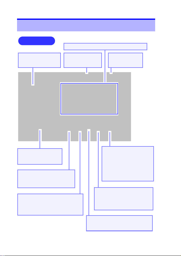
1.3 Names and Functions of Parts
Display: IR4057 (p.11), IR4056 (p.12)
Front Panel
*This figure is model IR4057.
LINE terminal
Connect the red
test lead.
EARTH terminal
Connect the black
test lead.
Measure key
Press to measure
insulation resistance.
Rotary selector
Select measurement
functions.
LIGHT key
Press this key to turn on and
off the light.
0 ADJ key
Press this key to perform zeroadjustment for the low resistance
range.
RELEASE key
Press this key before
measurement to set the
instrument to the 500 V or
1,000 V range (to prevent
erroneous application of
the test signal).
COMP key
Press this key to set t he comparator’s judgment reference
value.
Live circuit indicator
Lights up when voltage remains
between input terminals
1.3 Names and Functions of Parts
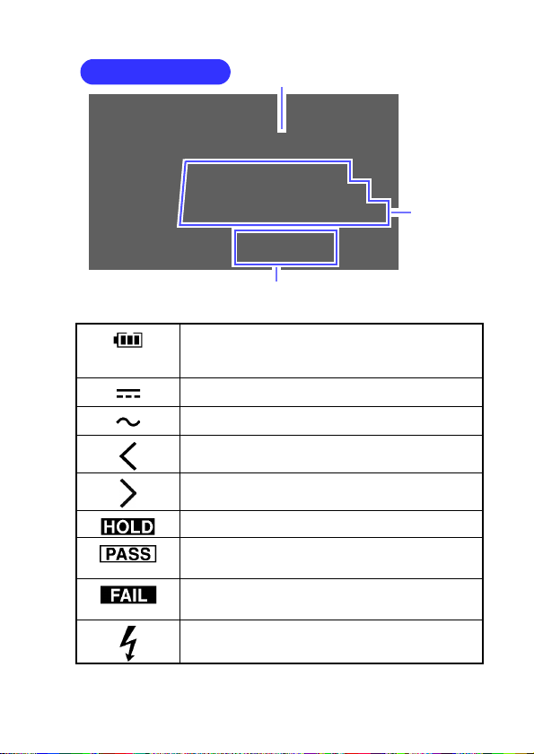
11
Display (IR4057)
Bar graph
Measured
value
Comparator judgment reference value
or 1-minute value
1.3 Names and Functions of Parts
Indicates the remaining battery life as one of three
levels. The battery mark outline will flash when the
remaining battery life reaches 0, at which point the
instrument will no longer perform measurement.
Turns on when the voltage measured with the V
range is DC.
Turns on when the voltage measured with the V
range is AC.
Flashes when the measured value is less than the
minimum display value.
Flashes when the measured value is greater than the
maximum display value.
Lights up when the measured value is held.
Turns on when the comparator judgment is PASS
(good).
See: "2.3.1 Setting the Comparator"(p.16)
Turns on when the comparator judgment is FAIL
(defective).
See: "2.3.1 Setting the Comparator"(p.16)
Flashes when a dangerous voltage exists between
the measurement terminals.
1
2
3
4
5
6
7
8
9
10
索引
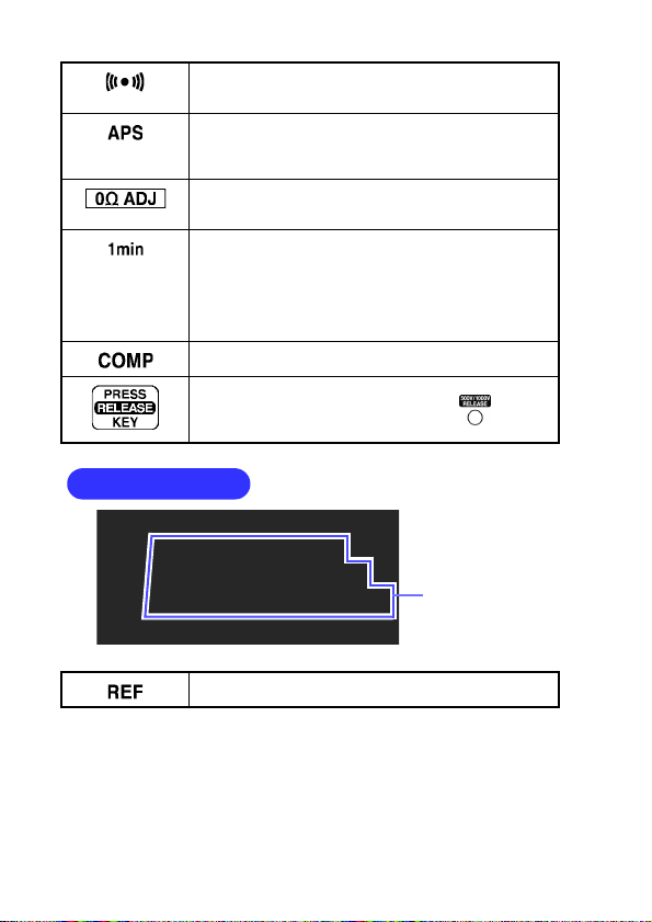
12
1.3 Names and Functions of Parts
Display (IR4056)
Measured value
or Comparator
reference value
When the comparator is enabled, the buzzer will
sound when the judgment result (PASS or FAIL) for
which this mark is lit up is encountered.
The auto power save function will activate 30
seconds after this mark starts flashing.
See:
"2.8 Auto power save (power-saving function)"(p.28)
Lights up when zero adjustment is made during low
resistance measurement.
See: "2.7 Low Resistance Measurement"(p.26)
Turns on when 1 minute has passed sin ce the start of
insulation resistance measurement. Indicates that the
resistance value on the bottom of the display is a
1-minute value (the measured value 1 minute after
the start of measurement).
See: "2.4.3 Displaying 1-min. Values (IR4057 Func-
tion)"(p.22)
Lights up when the comparator function is enabled.
See: "2.3 Configuring the Comparator"(p.15)
Turns on when the instrument is set to the 500 V
range or the 1,000 V range. Pressing turns off
the indicator and enables insulation measurement.
Lights up when the criterion for the comparator
function is indicated.
For more information about other display elements,
see " Display (IR4057)" (p.11).
 Loading...