

Hioki IR3455 Instruction Manual

99 Washington Street
Melrose, MA 02176
Phone 781-665-1400
Toll Free 1-800-517-8431
Visit us at www.TestEquipmentDepot.com
IR3455
Instruction Manual
HIGH VOLTAGE
INSULATION TESTER
Oct. 2016 Edition 1
IR3455A961-00 16-10H
EN

Contents
Introduction ......................................................1
Verifying Package Contents / Open the case ..1
Safety Information ...........................................5
Operating Precautions ..................................... 9
1 Overview 19
1.1 Product Overview ................................. 19
1.2 Features ...............................................21
1.3 Measurement Overview ....................... 23
1.4 Names and Functions of Parts ............. 29
1.5 Screen Setup ....................................... 33
2 Measurement Preparations 35
2.1 Supplying Power .................................. 35
2.1.1 Installing or Replacing the Battery...... 36
2.1.2 Installing the Battery Pack (Rechargeable
nickel-hydrogen battery) ..................... 39
2.1.3 Connecting the AC Adapter................ 45
2.1.4 Charging the Battery Pack ................. 47
2.2 Turning Power On and Off ................... 50
2.2.1 Auto Power Off ................................... 51
2.3 Setting and Checking Date and Time .. 52
2.3.1 Setting Date and Time........................ 52
2.3.2 Checking Date and Time.................... 55
2.4 Connecting Test Lead ..........................56
2.5 Connecting Temperature Sensor .........58
i
IR3455A961-00

ii
3 Measurement 59
3.1 Pre-Operation Inspection ..................... 59
3.2 Measuring Insulation Resistance ......... 62
3.2.1 Starting Measurement......................... 64
3.2.2 Ending Measurement.......................... 70
3.2.3 Checking and Deleting Held Data....... 72
3.2.4 Automatic Discharge Function ............ 73
3.2.5 Switching to Leakage Current Indication
.............................................................74
3.2.6 Insulation Resistance Measurement
Basis 75
3.2.7 Use of GUARD Terminal..................... 77
3.3 Measuring Voltage ............................... 79
3.4 Measuring Temperature ....................... 82
3.4.1 Measurement Procedure .................... 82
4 Advanced Measurement 85
4.1 Using Timer .......................................... 85
4.1.1 Setting Timer/Conducting Insulation
Resistance Measurement ...................85
4.2 Displaying PI and DAR .........................89
4.3 Temperature Compensation (TC) ........ 93
4.3.1 Performing Temperature Compensation
.............................................................93
4.3.2 Exiting Temperature Compensation
Mode ...................................................96
4.4 Step Voltage Test .................................97
4.4.1 Setting and Conducting a Step Voltage
Test .....................................................98
4.4.2 Viewing Detailed Data of Each Step after
Step Voltage Test .............................101
4.4.3 Exiting Step Voltage Test Mode........ 103

iii
5 Recording Measurement Data
(Memory Function) 105
5.1 Recording Measurement Data ........... 107
5.1.1 Manual Recording (Recording result of
one measurement session) 107
5.1.2 Logging Recording (Recording at regular
intervals) ........................................... 110
5.2 Checking Recorded Data ...................118
5.3 Deleting Recorded Data ..................... 123
5.3.1 Deleting Data of Chosen No............. 123
5.3.2 Deleting all Data ............................... 124
6 Other Functions 125
6.1 Changing and Checking Interval Setting
for PI Calculation ................................ 125
6.1.1 Changing Interval Setting ................. 125
6.1.2 Checking Interval Setting ................. 127
6.2 Changing and Checking Voltage
Application Time for Step Voltage Test
............................................................128
6.2.1 Changing Time Setting..................... 128
6.2.2 Checking Time Setting ..................... 130
6.3 Entering Temperature and Humidity
Measured with External Thermometer and
Hygrometer ........................................131
6.3.1 Entering and Saving ......................... 132
6.3.2 Clearing Indications of Temperature and
Humidity Stored Data ....................... 135
6.4 Communicating with PC ..................... 136
6.4.1 Installing Data Analysis Software
for 3455 ............................................. 137
6.4.2 Installing Driver................................. 138
6.4.3 Downloading Data to Save to PC/ Setting
up Instrument on PC 139

iv
7 Specifications 141
7.1 General Specifications ....................... 141
7.2 Measurement Specifications ..............146
7.2.1 Insulation Resistance Measurement. 146
7.2.2 Leakage Current Measurement ........ 149
7.2.3 Voltage Measurement....................... 150
7.2.4 Temperature Measurement .............. 151
7.3 9750-01/-02/-03/-11/-12/-13 and
9751-01/-02/-03 ALLIGATOR CLIPs
Specifications .....................................152
8 Maintenance and Service 153
8.1 Troubleshooting .................................154
8.2 Cleaning .............................................156
8.3 Error Display ......................................156
8.4 Performing System Reset .................. 158
8.5 Discarding the Instrument .................. 159
Appendix 163
Appendix 1 Test Voltage
Characteristic Graph .................163
Appendix 2 Example of Insulation Resistance
Criteria ......................................164
Appendix 3 Example of PI Criteria
(Polarization Index) ...................164
Appendix 4 Temperature Compensation Table
..................................................165
Introduction
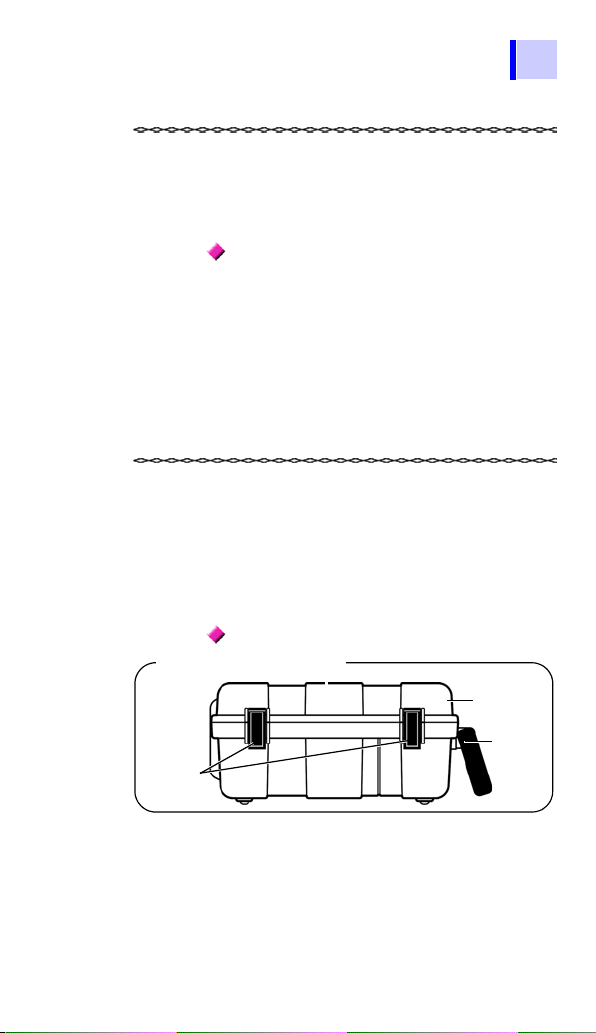
Appearance of Case
Cover
Latches
Handle
Introduction
1
Thank you for purchasing the Hioki IR3455
High Voltage Insulation Tester. To obtain
maximum performance from the instrument, please read this manual first, and
keep it handy for future reference.
Registered trade mark
• Microsoft and Windows are either registered trademarks or trademarks of
Microsoft Corporation in the United States
and other countries.
• Adobe and Adobe Reader are trademarks
of Adobe Systems Incorporated.
Verifying Package Contents / Open the case
When you receive the instrument, inspect it
carefully to ensure that no damage
occurred during shipping. In particular,
check the accessories, panel switches, and
connectors. If damage is evident, or if it fails
to operate according to the specifications,
contact your authorized Hioki distributor or
reseller.
Open the case
Open the case by releasing the two latches.
(See next page.)
2
Verifying Package Contents / Open the case
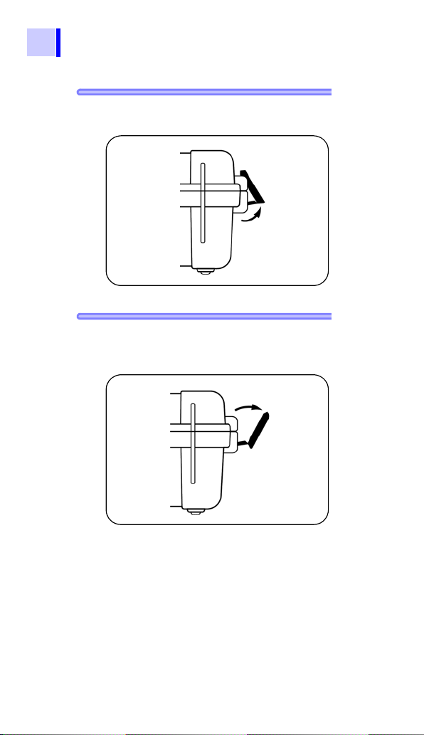
Procedure
1. Draw the latch outwards with your fin-
ger.
2. While raising the entire latch, place a
finger on the top of the latch and pull
it out.
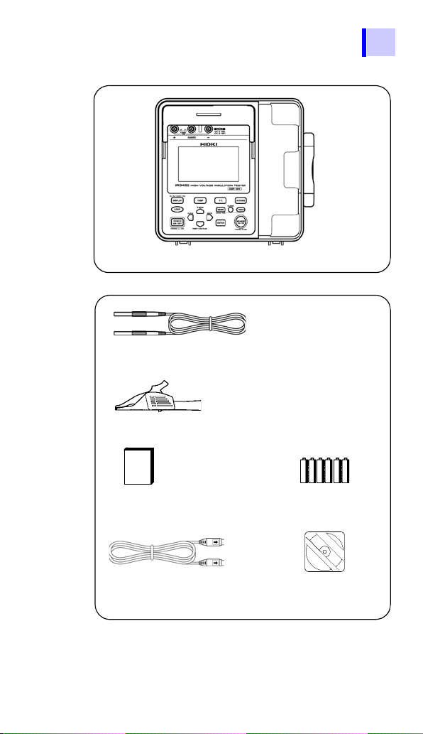
Verifying Package Contents / Open the case
IR3455 HIGH VOLTAGE INSULATION TESTER × 1
9750-01,-02,-03 TEST LEAD (Red, Black, Blue)
Lead length Approx. 3 m
×
1 each
LR6 alkaline battery × 6Instruction Manual
(This book)
×
1
USB Cable
×
1
9751-01,-02,-03 ALLIGATOR CLIP (Red, Black, Blue)
×
1 each
CD (Data Analysis
Software for 3455)*
×
1
Main Unit
Accessories
3
*The latest version can be downloaded
from our web site.
4
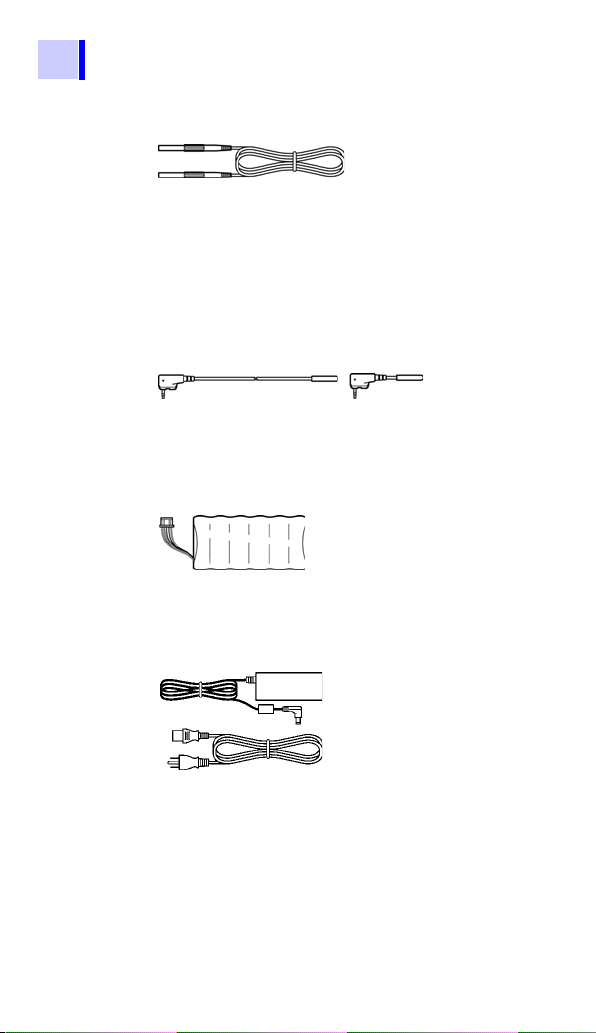
Verifying Package Contents / Open the case
Options
9750-11,-12,-13 TEST LEAD
(Red, Black, Blue Lead length Approx. 10 m)
The specifications for the 9750-11 and
9750-12 models differ from the standard
specifications in regards to temperature
characteristics.
See 7.2"Measurement Specifications" (page
146).
9631-01,-05 TEMPERATURE SENSOR
Used for temperature measurement.
9631-01: Lead length Approx. 1 m
9631-05: Lead length Approx. 5 cm
9459 BATTERY PACK
(Rechargeable nickel-hydrogen battery)
The 9753 AC ADAPTER is required for
charging.
9753 AC ADAPTER
Input: 100 to 240 VAC
Output: 12 V DC, 3.33 A
Safety Information
Safety Information
This instrument is designed to conform to IEC 61010 Safety
Standards, and has been thoroughly tested for safety prior
to shipment. However, using the instrument in a way not
described in this manual may negate the provided safety
features.
Before using the instrument, be certain to carefully read the
following safety notes:
Mishandling during use could result in
injury or death, as well as damage to the
instrument. Be certain that you understand the instructions and precautions in
the manual before use.
• Protective gear
This instrument measures live lines. To
prevent electric shock, use appropriate
protective insulation and adhere to
applicable laws and regulations.
• With regard to the electricity supply,
there are risks of electric shock, heat
generation, fire, and arc flash due to
short circuits. Individuals using an electrical measuring instrument for the first
time should be supervised by a technician who has experience in electrical
measurement.
5
6
Safety Information
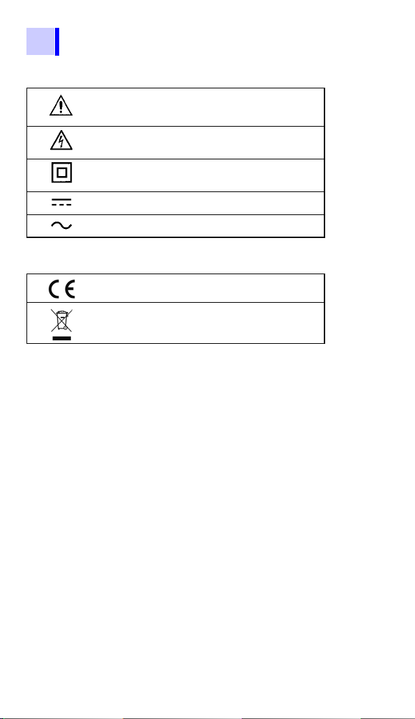
Symbols on the instrument
Indicates cautions and hazards. When the symbol is
printed on the instrument, refer to a corresponding
topic in the Instruction Manual.
Indicates that dangerous voltage may be present at
this terminal.
Indicates a double-insulated device.
Indicates DC (Direct Current).
Indicates AC (Alternating Current).
Symbols for standards
Indicates that the product conforms to regulations
set out by the EC Directive.
Indicates the Waste Electrical and Electronic Equipment Directive (WEEE Directive) in EU member
states.
Safety Information
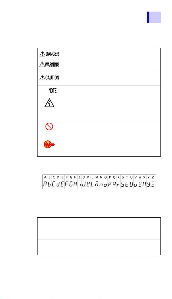
Notation
In this document, the risk seriousness and the hazard levels
are classified as follows.
Indicates an imminently hazardous situation that will
result in death or serious injury to the operator.
Indicates a potentially hazardous situation that may result in death or serious injury to the operator.
Indicates a potentially hazardous situation that may result in minor or moderate injury to the operator or damage to the instrument or malfunction.
Indicates advisory items related to performance or correct operation of the instrument.
Indicates a high voltage hazard.
If a particular safety check is not performed or the instrument is mishandled, this may give rise to a hazardous situation; the operator may receive an electric
shock, may get burnt or may even be fatally injured.
Indicates prohibited actions.
Indicates the location of reference information.
Indicates quick references for operation and remedies
for troubleshooting.
Additional information is presented below.
*
The instrument screen displays the alphanumeric characters as follows.
7
Accuracy
We define measurement tolerances in terms of rdg. (reading) and dgt. (digit) values, with the following meanings:
dgt.
(resolution)
rdg.
(reading or
displayed value)
The smallest displayable unit on a digital measuring instrument, i.e., the input value that
causes the digital display to show a "1" as the
least-significant digit.
The value currently being measured and indicated on the measuring instrument.
8
Safety Information
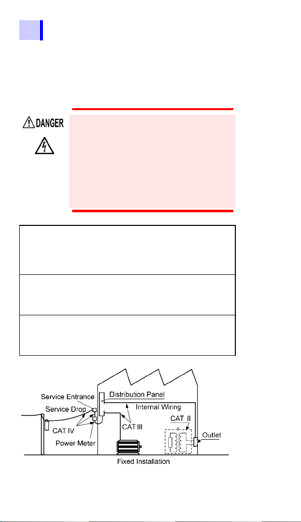
Measurement categories
To ensure safe operation of measuring instruments, IEC
61010 establishes safety standards for various electrical
environments, categorized as CAT II to CAT IV, and called
measurement categories.
• Using a measuring instrument in an
environment designated with a highernumbered category than that for which
the instrument is rated could result in a
severe accident, and must be carefully
avoided.
• Never use a measuring instrument that
lacks category labeling in a CAT II to
CAT IV measurement environment.
Doing so could result in a serious accident.
CAT II Primary electrical circuits in equipment con-
CAT III Primary electrical circuits of heavy equip-
CAT IV The circuit from the service drop to the ser-
nected to an AC electrical outlet by a power
cord (portable tools, household appliances,
etc.) CAT II covers directly measuring electrical outlet receptacles.
ment (fixed installations) connected directly
to the distribution panel, and feeders from
the distribution panel to outlets.
vice entrance, and to the power meter and
primary overcurrent protection device (distribution panel).

Operating Precautions
Preliminary Checks
Precautions during shipment
Operating Precautions
Follow these precautions to ensure safe operation and to
obtain the full benefits of the various functions.
Before using the instrument, verify that it
operates normally to ensure that no damage occurred during storage or shipping. If
you find any damage, contact your authorized Hioki distributor or reseller.
If the test lead or the instrument is damaged, there is a risk of electric shock.
Perform the following inspection before
using the instrument:
• Before using the instrument check that
the coating of the test leads are neither
ripped nor torn and that no metal parts
are exposed. Using the instrument
under such conditions could result in
electric shock. Replace the test leads
with those specified by our company.
• Verify that the instrument operates normally to ensure that no damage
occurred during storage or shipping. If
you find any damage, contact your
authorized Hioki distributor or reseller.
• To prevent an electric shock, confirm
that the white or red portion (insulation
layer) inside the cable is not exposed. If
a color inside the cable is exposed, do
not use the cable.
9
During shipment of the instrument, handle it
carefully so that it is not damaged due to a
vibration or shock.

10
Placement
Operating Precautions
Operating temperature and humidity range: P.141
Temperature and humidity range for guaranteed accuracy:
P. 1 48 to P.150
Installing the instrument in inappropriate
locations may cause a malfunction of
instrument or may give rise to an accident. Avoid the following locations:
• Exposed to direct sunlight or high temperature
• Exposed to corrosive or combustible
gases
• Exposed to a strong electromagnetic
field or electrostatic charge
• Near induction heating systems (such
as high-frequency induction heating
systems and IH cooking equipment)
• Susceptible to vibration
• Exposed to water, oil, chemicals, or solvents
• Exposed to high humidity or condensation
• Exposed to high quantities of dust particles
Operating Precautions
Shutter
11
Observe the following to avoid electric
shock and short circuits.
• Before connecting or disconnecting the
test leads to/from the instrument, be
sure to disconnect the test leads from
the object under test and turn off power.
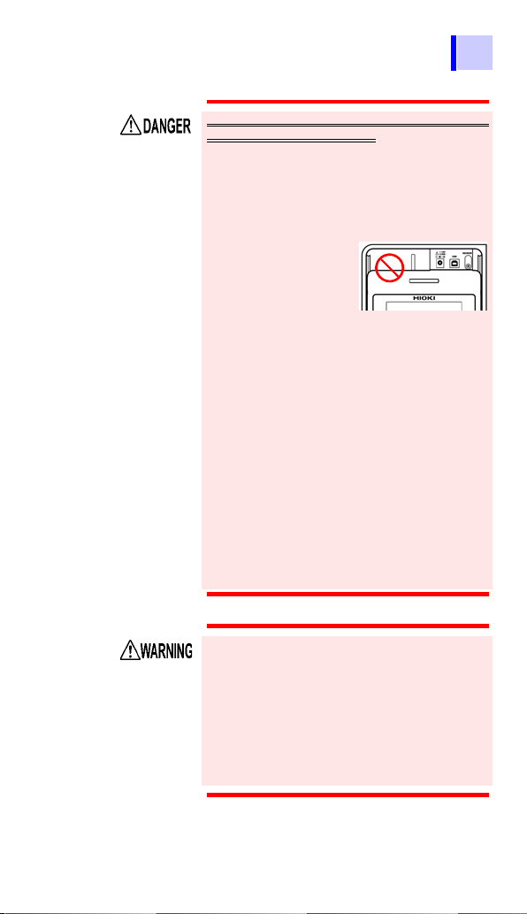
• Do not perform measurement with the
battery cover removed.
• Do not use the shutter if it is broken.
• To avoid electric
shock, do not
remove the instrument's case. The internal components of the instrument carry
high voltages and may become very hot
during operation.
• Do not use the instrument in environments containing ignitable gases,
explosive powders, etc. (Risk of explosion)
• Do not place the instrument on an
unstable table or an inclined place.
Dropping or knocking down the instrument can cause injury or damage to the
instrument.
• Do not use the instrument with circuits
that exceed its ratings or specifications.
Doing so may damage the instrument or
cause it to become hot, resulting in
bodily injury/electric shock.
• Before using the instrument, inform
those around you of your intention to
do so.
• To prevent instrument damage or
electric shock, use only the screw for
securing the battery cover in place that
are originally installed. If you have lost
a screw or find that a screw is damaged,
please contact your Hioki distributor for
a replacement.

12
Operating Precautions
• This instrument is designed for use indoors.
It can be operated at temperatures
between -10 to 50°C (14 to 122
°F
) without
degrading safety.
• To avoid damage to the instrument, protect
it from physical shock when transporting
and handling. Be especially careful to avoid
physical shock from dropping.
• If the protective functions of the instrument
are damaged, either remove it from service
or mark it clearly so that others do not use it
inadvertently.
• Touching any of the high-voltage points
inside the instrument is very dangerous.
Customers are not allowed to modify, disassemble, or repair the instrument. Doing so
may cause fire, electric shock, or injury.
• Place the cover on the instrument when not in
use.
• To avoid damage to the instrument, do not
connect an external device to the USB terminal or the temperature sensor terminal.
• The cable is hardened under the 0 degree
or colder environment. Do not bend or pull
it to avoid tearing its shield or cutting cable.
• This instrument is not drip-proof. Water
droplets on the grip or connector may result
in malfunctions.
• The protection rating for the enclosure of
this device (based on EN60529) is *IP40.
This indicates the degree of protection provided by
the enclosure of the device against use in hazardous locations, entry of solid foreign objects, and the
ingress of water.
4: Protected against access to hazardous parts with
wire measuring 1.0 mm in diameter. The equipment
inside the enclosure is protected against entry by
solid foreign objects larger than 1.0 mm in diameter.
0: The equipment inside the enclosure is not protected against the harmful effects of water.

Operating Precautions
13
• After use, always turn off the power.
• Standby State
The use of "standby state" in this manual
means that measurement is not being
performed and that no parameters are
set. This includes the state in which
is on.
• If the instrument is exposed to an abrupt
large variation in temperature,
condensation may occur, resulting in
measurement errors.
Leave the instrument in a new
environment for a while before starting
measurement.
14
Measurement
Operating Precautions
• It is recommend to make measurements
on the secondary side of distribution
panels. Measuring the primary side,
where the current capacity is much
larger, could cause damage to the
instrument or panel in the event of a
short-circuit.
• Do not short the two measurement lines
with the metal portion of the tips of the
test leads. Doing so may cause arcing
or otherwise result in a serious
accident.
• To avoid short circuit or electric shock,
do not touch the metal parts of the
connecting cable clips.
• To prevent electric shock, when measuring the voltage of a power line use
only the specified test lead.
• The optional test leads provided with
this instrument conform to the safety
standard EN61010. Use a test lead in
accordance with its defined measurement category and rated voltage.
To avoid damage to the instrument, do not
apply voltage or current to temperature
probe.

Operating Precautions
Electrical Units
CD precautions
Handling the Battery Pack
15
1 T (Tera ohm) =1000 G =1012
1 G (Giga ohm) =1000 M =10
1 M(Mega ohm) =1000 k =10
1 mA (Milliampere) =0.001 A =10
1 A (Micro ampere) =0.001 mA =10
1 nA (Nano ampere) =0.001 A=10
9
6
-3
A
-6
A
-9
A
• Exercise care to keep the recorded side
of discs free of dirt and scratches. When
writing text on a disc's label, use a pen or
marker with a soft tip.
• Keep discs inside a protective case and
do not expose to direct sunlight, high temperature, or high humidity.
• Hioki is not liable for any issues your
computer system experiences in the
course of using this disc.
Be sure to observe the following precautions. Incorrect handling may result in
liquid leaks, heat generation, ignition,
bursting and other hazards:
• The battery pack contains lye, which
may cause blindness if it comes into
contact with the eyes. Should battery
liquid get into your eyes, avoid rubbing
them. Flush them with water and seek
immediate medical attention.
• When storing the instrument, make sure
no objects that could short-circuit the
connectors are placed near them.

16
Operating Precautions
Observe the following to avoid damage to
the instrument:
• Use the battery pack in an ambient temperature range of 0 to 40°C and charge it in an
ambient temperature range of 0 to 40°C.
• If the battery pack fails to finish charging
within the stipulated time, disconnect the
AC adapter to stop charging and contact
your dealer or Hioki representative.
• Consult your dealer or nearest service station should liquid leaks, strange odor, heat,
discoloration, deformation and other abnormal conditions occur during use, charging
or storage. Should these conditions occur
during use or charging, turn off and disconnect the instrument immediately.
• Do not expose the instrument to water and
do not use it in excessively humid locations
or locations exposed to rain.
• Do not expose the instrument to strong
impacts and do not throw it around.
Heed the following instructions to avoid battery performance drop or leakage.
• Do no mix old and new batteries, or different types of batteries.
• Pay attention to the polarity markings "+-",
so that you do not insert the batteries the
wrong way around.
• Do not use batteries after their recommended expiry date.
• Do not leave a depleted batteries inside the
instrument.
• Replace batteries only with the specified
type.
• Remove the batteries or battery pack from
the instrument if it is to be stored for a long
time.

Operating Precautions
17
• The battery pack is a consumable. If you
are able to use the instrument for only a
limited period of time despite the battery
pack being properly charged, the battery
pack's service life is at an end, and it
should be replaced.
• When a battery pack that has not been
used for a long time is used, charging may
end before the battery pack is fully
charged. In such a case, repeat charging
and discharging a number of time before
use. (A battery pack may also be in such a
state immediately after purchase.)
• The life of the battery pack (when capacity
is 60% or more of initial capacity) is
approximately 500 charge-discharge
cycles. (The life differs depending on the
conditions of use.)
• To prevent battery pack deterioration
when the battery will not be used for 1
month or longer, remove it and store it in a
dry location with an ambient temperature
range of between -20°C to 30°C. Be sure
to discharge and charge it every two
months. Long-term storage at low battery
capacity will reduce performance.
• When a battery pack is used, the
instrument turns off automatically when
the capacity drops. Leaving the
instrument in this state for a long time may
lead to over discharge so be sure to turn
off the power switch on the instrument.
• The charging efficiency of the battery pack
deteriorates at high and low
temperatures.

1.1 Product Overview
19
Overview
1
1.1 Product Overview
The IR3455 is an insulation resistance tester with a wide
measurement range, for use in such environments involving
low to high voltage.
The instrument has the functions and purposes given
below.
Function Purpose
(Basic)
Insulation
resistance
measurement
Voltage
measurement
Temperature
measurement
(Applied)
Timer To automatically end measurement
Display
PI and DAR
values
Temperature
compensation (TC)
To test the insulation resistance of
an electrical facility.
To measure the voltage of an external circuit, e.g., commercial power
supply.
To measure a temperature
after a predetermined time.
To check whether the insulation resistance increases with time after a
voltage is applied.
[When the PI (polarization index)
value or the DAR (dielectric absorption ratio) value is close to 1, the instrument determines that the
insulation of the object to be measured has deteriorated.]
To obtain the insulation resistance
at various temperatures varied from
the actual environmental temperature at which measurement is performed.
Reference
page
3.2 (P.62)
3.3 (P.79)
3.4 (P.82)
4.1 (P.85)
4.2 (P.89)
4.3 (P.93)

20
1.1 Product Overview
Function Purpose
Step voltage
test
Memory
PC
Communication
To determine whether the insulation resistance of an object changes according to test voltage
applied.
To save the measurement data.
To create tables or graphs of the
data saved in the memory for reports, etc.
Reference
page
4.4 (P.97)
5 (P.105)
6.4 (P.136)

1.2 Features
Wide test voltage range
Generates a wide range of test voltages, from
250 V to 5 kV
The voltage may be chosen from the commonly used presets of 250 V, 500 V, 1 kV, 2.5
kV, and 5 kV; or set to a desired level by
increments or decrements of 25 V or 100 V.
3.2 "Measuring Insulation Resistance" (page 62)
Insulation diagnoses
For automatic calculation and indication of
PI (polarization index) and DAR (dielectric
absorption ratio), step voltage testing, and
temperature compensation.
4 "Advanced Measurement" (page 85)
Large memory
Stores up to 100 manual records and 10
logging records. The stored data may be
displayed on the LCD or downloaded to a
PC.
5 "Recording Measurement Data (Memory Function)" (page 105)
6.4 "Communicating with PC" (page 136)
1.2 Features
21
Large, clear display
The large display provides easy viewing.
Measurements may also be displayed
using a logarithmic bar graph, offering the
feel of an analog meter.
The LCD is backlit, enabling measurement
in poor lighting conditions.

22
1.2 Features
PC software with report creation/
printing feature
The instrument has a USB interface. Data
stored in the memory may be downloaded
to PC using the data download software.
The same software also enables reports to
be created and printed with ease.
6.4 "Communicating with PC" (page 136)
Compact hard case
The case is durable-designed to withstand
the toughest of working conditions, compact, and highly portable.
Dual battery power supply
The instrument can be powered by either
alkaline or rechargeable nickel-hydrogen
batteries. (Selectable via switch)
2.1.1 "Installing or Replacing the Battery" (page
36)
2.1.2 "Installing the Battery Pack (Rechargeable
nickel-hydrogen battery)" (page 39)

1.3 Measurement Overview
Purpose : Inspection of high-voltage electrical
facilities
Location : High-voltage receiving station or trans-
forming station
Test object : Large motors, transformers, cables,
etc.
• Measures insulation resistance, voltage and temperature.
• Stores measurement data in the internal memory.
• Downloads data to a PC for table, graph, or report
creation.
Prepare for measurement
2 "Measurement Preparations" (page 35)
1.3 Measurement Overview
This instrument is designed for measurement of the following:
Measurement condition
When measuring insulation resistance, ensure that power
supply to the object under test is turned off.
You will need:
• IR3455 HIGH VOLTAGE INSULATION TESTER
• AA alkaline batteries (LR6), or
9459 BATTERY PACK
• 9750-01,-02,-03 TEST LEAD
• 9751-01,-02,-03 ALLIGATOR CLIP
• 9631-01,-05 TEMPERATURE SENSOR (for temperature
measurement)
23
Flow of measurement
Before starting measurement, check the following:
• The power supply method.
• The power ON/OFF method.
• That date and time are set.
• Connection of test leads, temperature sensor, and USB
cable.
24
Start measurement.
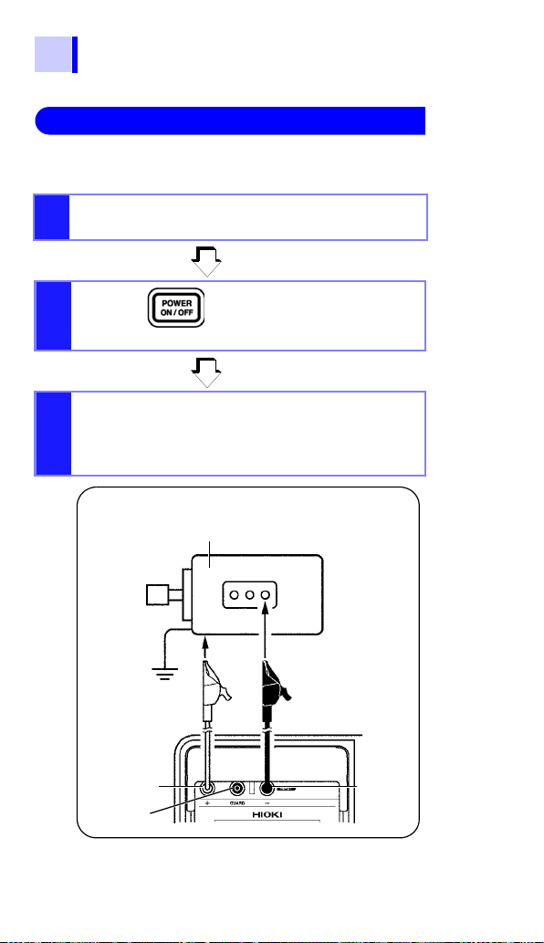
GUARD
terminal
Warning: Confirm that the power supply to the
object under test has been turned off.
Object to be measured (Ex.: Motor)
+ terminal
- terminal
Test lead (Red)
Attach to a metal
chassis or a ground
terminal.
Test lead (Black)
Attach to a metal part
of the power supply
terminal.
1.3 Measurement Overview
Insulation Resistance Measurement
3.2 "Measuring Insulation Resistance" (page 62)
Make sure that power supply to the object under
1.
test is turned off.
2.
Press the key to turn on
the instrument.
Connect the test leads into the
3.
"+" and "-" terminals of the instrument and to the object to be
tested.
2.2 (page 50)
2.4 (page 56)
3.2.1 (page 64)
1.3 Measurement Overview
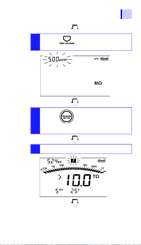
4.
Press the key and set
the test voltage.
5.
Press the key to gener-
ate a voltage and start measurement.
Read the indication.
6.
3.2.1 (page 64)
3.2.1 (page 64)
3.2.1 (page 64)
25

26
1.3 Measurement Overview
7.
Press the key to stop
voltage generation and measurement.
3.2.2 (page 70)
The automatic discharge function
8.
is activated.
Measurement is terminated when
9.
the voltage falls below 10 V.
3.2.4 (page 73)
 Loading...