

IM7580A-1
HIOKI IM7585A981-05
IM7580A
IM7581
IM7583
IM7585
IM7587
IM7580A-2
IM7581-01
IM7581-02
IM7583-01
IM7583-02
IM7585-01
IM7585-02
IM7587-01
IM7587-02
Instruction Manual
IMPEDANCE ANALYZER
Apr. 2020 Revised edition 5
IM7585A981-05 20-04H
EN

HIOKI IM7585A981-05
Contents
HIOKI IM7585A981-05
Introduction ................................................ 1
Verifying Package Contents ..................... 1
Options (Sold Separately) ......................... 2
Safety Information ..................................... 2
Operating Precautions .............................. 5
1 Overview 9
1.1 Overview and Features .................... 9
1.2 Names and Functions of Parts ......11
1.3 Screen Operations ......................... 14
2 Measurement
Preparations 17
2.1 Connecting the Test Head ............. 17
2.2 Pre-Operation Inspection .............. 19
2.3 Connecting the Power Cord .......... 20
2.4 Connecting a Measurement
Cable/Fixture .................................. 21
2.5 Connecting an Interface ................ 22
2.6 Turning the Power ON and OFF .... 24
2.7 Select the Measurement Mode ...... 25
3 LCR Function 27
3.1 LCR Function .................................. 27
3.1.1 Flowchart ..................................................... 27
3.1.2 Screen map ................................................. 28
3.1.3 Measurement screen ................................... 30
3.1.4 Status and error display of this instrument .... 31
3.2 Setting Basic Settings of
Measurement Conditions .............. 32
3.2.1 Setting Display Parameters .......................... 32
3.2.2 Starting Measurement at Any Arbitrary
Timing (Trigger) ...........................................33
3.2.3 Setting the Delay Time from Trigger to
Measurement Start (Trigger Delay) .............. 34
3.2.4 Applying the Signal to the Sample during
Measurement Only
(Trigger Synchronous Output) ...................... 35
3.2.5 Setting the Measurement Frequency ........... 37
3.2.6 Setting the Measurement Signal Level ......... 38
3.2.7 Setting the Measurement Speed ..................40
3.2.8 Display with Average Values (Average) ........ 41
3.3 Judging Measurement Results ..... 43
3.3.1 Setting the Judgment Mode ......................... 44
3.3.2 Judging with Upper and Lower Limit
Values (Comparator Judgment Mode) .......... 46
3.3.3 Classifying Measurement Results
(BIN Judgment) ............................................ 53
4 Analyzer Function 59
4.1 Analyzer Function .......................... 59
4.1.1 Flowchart ..................................................... 60
4.1.2 Screen map ................................................. 62
4.1.3 Measurement screen ................................... 64
4.1.4 Types of graph .............................................65
4.1.5 Status and error display of this instrument ....66
4.2 Setting Basic Settings of
Measurement .................................. 67
4.2.1 Setting the Measurement Parameters .......... 67
4.2.2 Starting Measurement at Any Arbitrary
Timing (Trigger) ...........................................68
4.2.3 Setting the Delay Time from Trigger to
Measurement Start (Trigger Delay) .............. 69
4.2.4 Applying the Signal to the Sample during
Measurement Only
(Trigger Synchronous Output) ...................... 70
4.2.5 Setting the Sweep Parameter ...................... 72
4.3 Sweep measurement ..................... 73
4.3.1 Setting the Sweep Method ........................... 74
4.3.2 Setting the Sweep Range ............................76
4.3.3 Normal Sweep ............................................. 81
4.3.4 Segment Sweep and Segment Interval
Sweep ......................................................... 84
4.4 Set Measurement Conditions for
Sweep Points .................................. 87
4.4.1 Setting the Measurement Signal Frequency . 87
4.4.2 Setting the Measurement Signal Level ......... 88
4.4.3 Setting the Measurement Speed ..................90
4.4.4 Displaying Average Values (Average) .......... 90
4.4.5 Setting the Delay Time for Each Sweep
Point (Point Delay) ....................................... 91
4.5 Setting the Graph Display Method 92
4.5.1 Setting the Horizontal Axis ........................... 92
4.5.2 Setting the Vertical Axis ...............................95
4.5.3 ConguringtheX-YDisplayVerticalAxis
Reversal Setting ..........................................98
4.5.4 SettingtheX-YDisplayScaleWidth ............ 99
4.5.5 Setting Grid Display ................................... 100
4.5.6 Setting Overlay .......................................... 101
4.6 Setting the Cursor ........................ 102
4.6.1 Selecting the Cursor to Display in the
Screen ....................................................... 102
4.6.2 Setting Cursor Move .................................. 103
4.7 Performing Measurement Value
Search ........................................... 104
4.7.1 Setting the Search Target Parameter ......... 104
4.7.2 Setting the Search Type .............................105
4.7.3 Using the Automatic Search Function ......... 106
4.7.4 Executing Search....................................... 107
4.8 Judging Measurement Results
(Comparator Function) ................ 108
4.8.1 Setting the Judgment Mode ....................... 108
1
1
2
2
3
3
44
4
5
6
7
8
9
10
Appx. Index
IM7585A981-05
i
i

Contents
HIOKI IM7585A981-05
4.8.2 Setting the Parameter to be Judged
(Spot Judgment Excluded) ..........................110
4.8.3 Setting the Judgment Area to Display in
the Measurement Screen
(Spot Judgment Excluded) .......................... 111
4.8.4 Area Judgment ...........................................112
4.8.5 PeakJudgment ...........................................116
4.8.6 Spot Judgment .......................................... 120
4.9 Equivalent Circuit Analysis
Function ........................................ 125
4.9.1 Equivalent Circuit Analysis Function ........... 125
4.9.2 ConguringBasicSettingsforAnalysis ...... 126
4.9.3 Performing Equivalent Circuit Analysis ....... 133
4.9.4 Simulating Frequency Characteristics ........ 136
4.9.5 Settings to Judge Analysis Results ............. 138
5 Calibration and
Compensation 141
5.1 Calibration and Compensation
Function Overview ....................... 141
5.2 Calibration .................................... 145
5.2.1 Setting Calibration Conditions and
Executing Calibration [CAL] .......................145
5.3 Error Compensation .................... 154
5.3.1 Setting the Electric Length Compensation
[LENGTH] .................................................. 154
5.3.2 Setting Compensation Conditions and
Executing Compensation [COMPEN] ......... 155
5.4 Calculating Values (Scaling) ....... 160
5.5 Troubleshooting of
Compensation .............................. 162
6 Continuous
Measurement Function 163
6.1 Continuous Measurement
Function ........................................ 163
6.1.1 Operationow ........................................... 164
6.1.2 Measurement screen ................................. 165
6.2 ConguringContinuous
Measurement Basic Settings ...... 166
6.3 Executing and Stopping
Continuous Measurement ........... 167
6.4 Checking Continuous
Measurement Results .................. 168
6.5 Cancels the Measurement if an
Error is Detected .......................... 169
7 Application function 171
7.1 Checking Contact Defects and
the Contact State
(Contact Check Function) ........... 171
7.1.1 Setting the DC Measurement ..................... 171
7.1.2 Setting the Judgment ................................. 174
7.1.3 DetectingOPENduring2-terminal
Measurement (Hi Z Reject Function) .......... 176
7.1.4 Monitoring the Detection Level
(Detection Level Monitoring Function) ........ 177
7.2 Other Functions ........................... 179
7.2.1 Set the number of display digits ................. 179
7.2.2 Setting Absolute Value Display (LCR only) . 180
7.2.3 Setting the Communication Measurement
Data Type .................................................. 181
7.3 Common Functions
(LCR Mode, ANALYZER Mode) .... 182
7.3.1 Saving Measurement Results
(Memory Function) ..................................... 182
7.3.2 Setting the Screen Display ......................... 184
7.3.3 Setting the Beep Sound ............................. 188
7.3.4 DisplaytheWarm-upMessage .................. 189
7.3.5 Disabling Key Operation
(Key-lockFunction) .................................... 190
7.3.6 Setting the Communication Measurement
Data Type .................................................. 194
7.3.7 Initializing the Instrument (System Reset) ... 196
8 External Control 199
8.1 External Input/Output Connector
and Signals ................................... 199
8.2 Timing Chart ................................. 209
8.2.1 LCR mode ................................................. 209
8.2.2 ANALYZERMode .......................................211
8.2.3 CONTINUOUS measurement mode .......... 213
8.3 Internal Circuit .............................. 215
8.4 External Control Q&A .................. 218
8.5 Measurement Using a Computer 218
8.6 External Control I/O Settings ...... 219
8.6.1 Enabling Trigger Input During
Measurement (Trigger Enabled) ................. 219
8.6.2 Setting Valid Edge of Trigger Input
(Trigger Edge) ............................................ 220
8.6.3 Setting Reset of Judgment Results
(Judgment Result Signal Reset) ................. 221
8.6.4 Setting the EOM Output Method
(EOM mode) .............................................. 222
8.6.5 Setting Delay Time from Judgment
Results Output until Output of EOM
(LOW)(JUDGE-EOM) ............................... 224
8.6.6 SetaDelayforINDEXSignalOutput
(INDEXDelay) ........................................... 225
ii

Contents
HIOKI IM7585A981-05
9 Saving and Loading
Panel Information 227
9.1 Saving Measurement Conditions
(Panel Save Function) .................. 228
Loading Measurement Conditions
9.2
(Panel Load Function) ................. 231
9.3 Changing a Panel Name .............. 232
9.4 Deleting a Panel ........................... 233
10 Setting the SYSTEM 235
10.1 Setting the Interface ..................... 235
Checking the Instrument Version
10.2
10.3 Self Checks (Self Diagnosis) ....... 237
10.3.1 Panel Test .................................................. 237
10.3.2 Panel Compensation .................................. 238
10.3.3 Screen Display Test ................................... 239
10.3.4 ROM/RAM Test .........................................240
10.3.5 I/O Test ...................................................... 241
10.4 Setting the Date and Time ........... 242
. 236
11.7.5 CheckingtheContentsofFiles .................. 274
12 Specications 275
12.1 GeneralSpecications ................ 275
12.2 MeasurementSpecications ....... 276
12.3 Functionalspecication .............. 285
12.4 InterfaceSpecications ............... 291
12.5 Measurement Accuracy ............... 292
12.5.1 Example: Calculation of Accuracy .............. 292
12.5.2 Measurable Range .................................... 299
13 Maintenance and
Service 301
13.1 Inspection, Repair and Cleaning 301
13.2 Disposal ........................................ 303
13.3 Troubleshooting ........................... 305
13.4 Error Display ................................. 310
Appendix A1
1
11
2
12
3
13
44
5
11 Using USB Flash Drive 243
11.1 Overview ....................................... 243
11.2 Inserting and Removing USB
Flash Drive .................................... 245
11.3 Screen Display When Using USB 246
11.4 Saving Data to USB Flash Drive . 247
11.4.1 Saving Measurement Result as Text .......... 247
11.4.2 Saving Measurement Screen
(Screen Copy) ........................................... 258
11.4.3 Setting Save Folder ................................... 260
11.4.4 Saving Memory Data ................................. 262
11.5 Saving Instrument Settings to
USB Flash Drive ........................... 263
11.5.1 Saving Instrument Settings ........................ 263
11.5.2 Saving All Settings of Instrument
(ALL SAVE Function) ................................. 264
11.6 Loading Binary Data from USB
Flash Drive .................................... 265
11.6.1 Loading Measurement Data
(ANALYZERFunction) ............................... 265
11.6.2 Loading Instrument Settings ....................... 266
11.6.3 Loading All Settings (ALL LOAD Function) .268
11.7 Editing Data Saved in USB
Flash Drive .................................... 269
11.7.1 Formatting a USB Flash Drive .................... 269
11.7.2 Creating a Folder in USB Flash Drive ......... 270
11.7.3 Changing Folder Name or File Name in
USB Flash Drive ........................................ 271
11.7.4 Deleting a File or Folder in USB Flash
Drive .......................................................... 273
Appx. 1
Appx. 2
Appx. 3 Series Equivalent Circuit
Appx. 4 Selecting the Equivalent
Appx. 5 Maintenance of Coaxial
Appx. 6 Rack Mounting .........................A7
Appx. 7 Dimensional Diagram ............A15
Measurement Parameters
and Calculation Formula
Countermeasures to
Prevent Entry of External Noise
Countermeasures to prevent entry of
noise from the power supply line ............... A3
Countermeasures to prevent entry noise
from the measurement cables ................... A3
Mode and Parallel
Equivalent Circuit Mode .......... A4
Circuit Model ............................ A5
Connector ................................. A6
Plate dimension ......................................... A8
Installation procedure .............................. A12
..........A1
A3
Index Ind.1
6
7
8
9
10
Appx. Index
iii

Contents
HIOKI IM7585A981-05
iv

Measurement Process
HIOKI IM7585A981-05
Read “Operating Precautions” (p. 5) before installing and connecting this instrument.
Refer to “Appx. 6 Rack Mounting” (p. A7) for rack mounting.
Install the instrument (p. 5)
Connect the test head (p. 17)
Connect the power cord (p. 20)
Connect measurement cables, optional Hioki probes, or test xture (p. 21)
Connect external interfaces (as required) (p. 235)
Inspect all the connections (p. 19)
Turn ON the power supply (p. 24)
Perform calibration / compensation (p. 141)
Set measurement conditions
Connect to the test sample
Make measurements
Turn OFF the power supply (p. 24)
After using the instrument, remove the test sample and turn OFF the power supply.
Calibration/compensation execution timing
• Before measurements
• After the length of measurement cable is changed
• After the type of measurement sample is changed
• After the xture is changed

HIOKI IM7585A981-05
Introduction
HIOKI IM7585A981-05
Introduction
Thank you for purchasing the HIOKI IM7580A, IM7581, IM7583, IM7585, IM7587 Impedance Analyzer.
To obtain maximum performance from the instrument, please read this manual rst, and keep it handy for
future reference.
The screen display has been explained using Model IM7585 as an example.
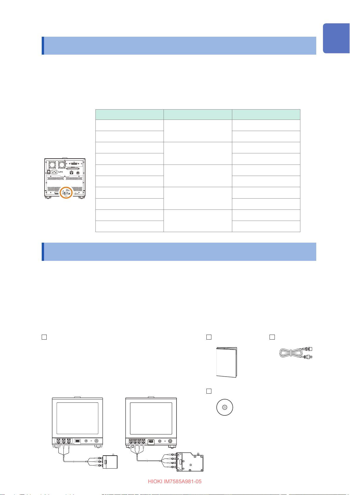
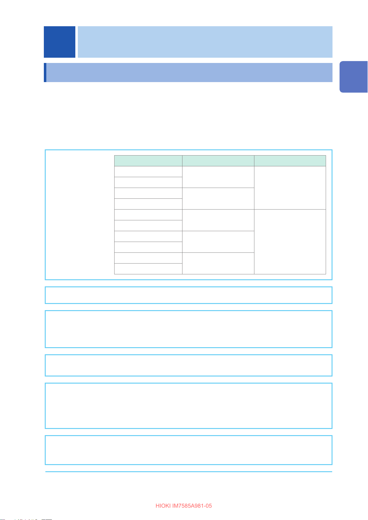
Model Information
Model Measurement frequency Cable length
1
2
Rear
(Example: IM7585)
IM7580A-1
1 MHz to 300 MHz
IM7580A-2 2 m
IM7581-01
100 kHz to 300 MHz
IM7581-02 2 m
IM7583-01
1 MHz to 600 MHz
IM7583-02 2 m
IM7585-01
1 MHz to 1.3 GHz
IM7585-02 2 m
IM7587-01
1 MHz to 1.3 GHz
IM7587-02 2 m
1 m
1 m
1 m
1 m
1 m
Verifying Package Contents
• When you receive the instrument, inspect it carefully to ensure that no damage occurred during
shipping.
In particular, check the accessories, panel switches, and connectors. If damage is evident, or if it fails to
operate according to the specications, contact your authorized Hioki distributor or reseller.
• Store the packaging in which the instrument was delivered, as you will need it when transporting the
instrument.
3
4
5
6
7
Conrm that the following items have been provided:
IM7580A, IM7581, IM7583, IM7585, IM7587 Impedance Analyzer ×1
• Test head ×1
• Measurement cable ×1
(IM7580A-1: 1 m, IM7580A-2: 2 m,
IM7581-01: 1 m, IM7581-02: 2 m,
IM7583-01: 1 m, IM7583-02: 2 m,
IM7585-01: 1 m, IM7585-02: 2 m,
IM7587-01: 1 m, IM7587-02: 2 m)
IM7580A, IM7581 IM7583, IM7585, IM7587
Instruction Manual ×1 Power cord ×1
Impedance Analyzer Application Disc ×1
(Communications user manual [PDF],
communications commands manual,
USB driver, sample application, and initial
settings table)
• The latest version can be downloaded
from our website.
8
9
10
Appx. Ind.
1
Options (Sold Separately)
HIOKI IM7585A981-05
Options (Sold Separately)
Contact your authorized Hioki distributor or reseller when ordering.
The options are subject to change. Visit our website for updated information.
Test xtures
IM9200 Test Fixture Stand
IM9201 SMD Test Fixture (for SMDs)
IM9202 Test Fixture (for through-hole components and SMDs)
IM9906 Adapter (3.5mm/7mm)
IM9905 Calibration Kit
Interfaces
Z3000 GP-IB Interface
Z3001 RS-232C Interface
Connection cables
9151-02 GP-IB Connector Cable (2 m)
9637 RS-232C Cable (9pin-9pin/1.8m)
Safety Information
This instrument is designed to conform to IEC 61010 Safety Standards, and has been thoroughly tested
for safety prior to shipment. However, using the instrument in a way not described in this manual may
negate the provided safety features.
Before using the instrument, be certain to carefully read the following safety notes.
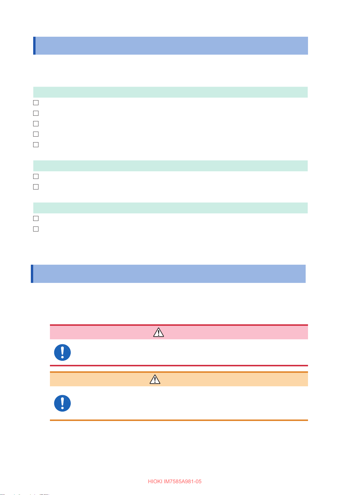
DANGER
Mishandling during use could result in injury or death, as well as damage to the
instrument. Be certain that you understand the instructions and precautions in
the manual before use.
2
WARNING
With regard to the electricity supply, there are risks of electric shock, heat
generation, re, and arc discharge due to short circuits. If persons unfamiliar
with electricity measuring instrument are to use the instrument, another person
familiar with such instruments must supervise operations.

Notation
HIOKI IM7585A981-05
In this manual, the risk seriousness and the hazard levels are classied as follows.
Safety Information
DANGER
WARNING
CAUTION
IMPORTANT
*
Symbols on the instrument
Indicates an imminently hazardous situation that will result in death or serious injury to
the operator.
Indicates a potentially hazardous situation that may result in death or serious injury to
the operator.
Indicates a potentially hazardous situation that may result in minor or moderate injury
to the operator or damage to the instrument or malfunction.
Indicates information related to the operation of the instrument or maintenance tasks
with which the operators must be fully familiar.
Indicates a high voltage hazard.
If a particular safety check is not performed or the instrument is mishandled, this may
give rise to a hazardous situation; the operator may receive an electric shock, may get
burnt or may even be fatally injured.
Indicates prohibited actions.
Indicates the action which must be performed.
Additional information is presented below.
1
2
3
4
5
Indicates cautions and hazards. When the symbol is printed on the instrument, refer to a
corresponding topic in the Instruction Manual.
Indicates AC (Alternating Current).
Indicates the ON side of the power switch.
Indicates the OFF side of the power switch.
Symbols for standards
Indicates the Waste Electrical and Electronic Equipment Directive (WEEE Directive) in EU
member states.
Indicates that the product conforms to regulations set out by the EU Directive.
6
7
8
9
10
Appx. Ind.
3
Safety Information
HIOKI IM7585A981-05
Accuracy
We dene measurement tolerances in terms of f.s. (full scale), rdg. (reading) and dgt. (digit) values,
with the following meanings:
(maximum display value or scale length)
f.s.
The maximum displayable value or scale length. This is usually the name of the currently
selected range.
rdg.
dgt.
(reading or displayed value)
The value currently being measured and indicated on the measuring instrument.
(resolution)
The smallest displayable unit on a digital measuring instrument, i.e., the input value that
causes the digital display to show a “1” as the least-signicant digit.
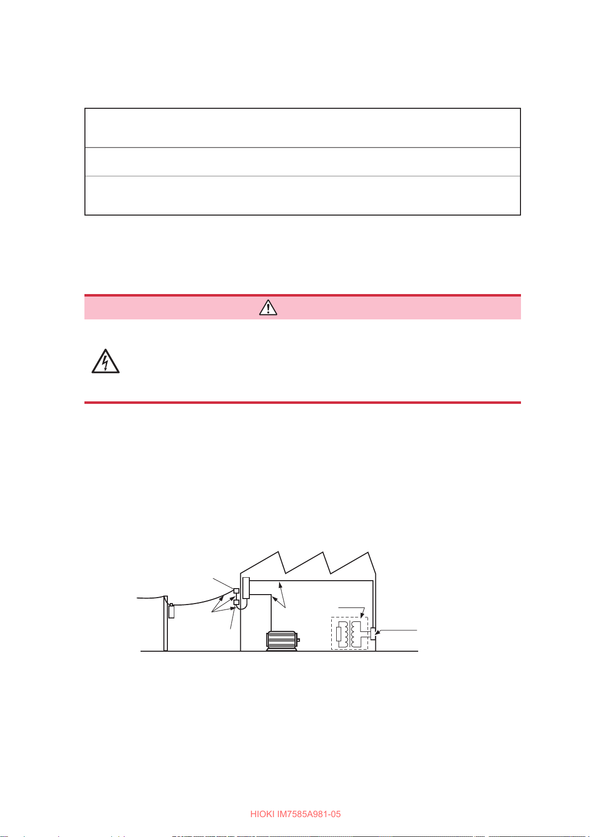
Measurement categories
To ensure safe operation of measurement instruments, IEC 61010 establishes safety standards
for various electrical environments, categorized as CAT II to CAT IV, and called measurement
categories.
DANGER
• Using a measuring instrument in an environment designated with a higher-
numbered category than that for which the instrument is rated could result in a
severe accident, and must be carefully avoided.
• Using a measuring instrument without categories in an environment designated
with the CAT II to CAT IV category could result in a severe accident, and must
be carefully avoided.
CAT II: When directly measuring the electrical outlet receptacles of primary electrical circuits
in equipment connected to an AC electrical outlet by a power cord (portable tools,
household appliances, etc.).
CAT III: When measuring the primary electrical circuits of heavy equipment (xed installations)
connected directly to the distribution panel, and feeders from the distribution panel to
outlets.
CAT IV: When measuring the circuit from the service drop to the service entrance, and to the
power meter and primary overcurrent protection device (distribution panel).
4
Service entrance
Service drop
CAT IV
Power meter
Distribution panel
Internal wiring
CAT III
Fixed installations
CAT II
T
Outlet

Operating Precautions
HIOKI IM7585A981-05
Operating Precautions
Follow these precautions to ensure safe operation and to obtain the full benets of the various functions.
WARNING
If the measurement cable or the instrument is damaged, there is a risk of electric
shock. Perform the following inspection before using the instrument:
• Before using the instrument, make sure that the insulation on the measurement
cables are undamaged and that no bare conductors are improperly exposed. If
the instrument is damaged, contact your authorized Hioki distributor or reseller.
• Before using the instrument for the rst time, verify that it operates normally
to ensure that no damage occurred during storage or shipping. If you nd any
damage, contact your authorized Hioki distributor or reseller.
CAUTION
Avoid using an uninterruptible power supply (UPS) or DC/AC inverter with rectangular
wave or pseudo-sine-wave output to power the instrument. Doing so may damage the
instrument.
Instrument installation
For details on the operating temperature and humidity, refer to the specications (p. 275).
1
2
3
4
5
Installing the instrument in inappropriate locations may cause a malfunction of
instrument or may give rise to an accident. Avoid the following locations.
• Exposed to direct sunlight or high temperature
• Exposed to corrosive or combustible gases
• Exposed to a strong electromagnetic eld or electrostatic charge
• Near induction heating systems (such as high-frequency induction heating
systems and IH cooking equipment)
• Susceptible to vibration
• Exposed to water, oil, chemicals, or solvents
• Exposed to high humidity or condensation
• Exposed to high quantities of dust particles
Installation method
Example: IM7585
50 mm or more
WARNING
To prevent overheating, be sure to leave the specied
clearances around the instrument.
• Install the instrument with the bottom facing down.
• Vents must not be obstructed.
• A distance of 50 mm or more must be maintained between the
rear and the surroundings.
6
7
8
9
10
Appx. Ind.
5

Operating Precautions
HIOKI IM7585A981-05
Warranty
Hioki disclaims responsibility for any direct or indirect damages that may occur if this instrument has been
combined with other devices by a systems integrator prior to sale or during resale. Please note.
Handling the instrument
DANGER
• To avoid electric shock, do not remove the instrument’s case. The internal
components of the instrument carry high voltages and may become very hot
during operation.
• Do not allow the instrument to get wet, and do not take measurements with wet
hands. This may cause an electric shock.
CAUTION
• If the instrument exhibits abnormal operation or display during use, review the
information given in “13.3 Troubleshooting” (p. 305) and “13.4 Error Display” (p. 310)
before contacting your authorized Hioki distributor or reseller. Do not connect charged
capacitors, input voltage or current to the measuring terminals. The instrument will get
damaged.
• To avoid damage to the instrument, protect it from physical shock when transporting
and handling. Be especially careful to avoid physical shock from dropping.
• This instrument is not designed to be entirely water- or dust-proof. Do not use it in an
especially dusty environment, nor where it might be splashed with liquid. This may
cause damage.
• Do not use excessive force on the touch panel, and do not use hard or sharp objects
that could damage the touch screen.
• Do not apply heavy downward pressure with the stand extended. The stand could be
damaged.
• To avoid damage to the instrument, do not short-circuit the terminal/output terminal
and do not input voltage to the terminal/output terminal.
• After use, always turn OFF the power.
IMPORTANT
This instrument may cause interference if used in residential areas. Such use must be avoided
unless the user takes special measures to reduce electromagnetic emissions to prevent
interference to the reception of radio and television broadcasts.
Before turning ON the power
• Before turning the instrument on, make sure the supply voltage matches that
indicated on its power connector. Connection to an improper supply voltage
may damage the instrument and present an electrical hazard. Be careful to
avoid connecting the supply voltage improperly. Doing so may damage the
instrument’s internal circuitry. To avoid electrical accidents and to maintain the
safety specications of this instrument, connect the power cord provided only
to an outlet.
6
WARNING

Handling of cords and xtures
HIOKI IM7585A981-05
Use only the designated power cord with this instrument. Using other power cords may
cause re.
Operating Precautions
WARNING
1
• To avoid damaging the power cord, grasp the plug, not the cord, when unplugging it
• To avoid breaking the cables or probes, do not bend or pull them.
• Bare conductors may get exposed if the insulation melts. Keep the cables well away
• Keep in mind that, in some cases, conductors to be measured may be hot.
• Use only the specied measurement cables. Using a non-specied measurement cable
may result in incorrect measurements due to poor connection or other reasons.
• Read the instruction manual supplied with the product to be used before using a xture.
CD precautions
• Exercise care to keep the recorded side of discs free of dirt and scratches. When writing
text on a disc’s label, use a pen or marker with a soft tip.
• Keep discs inside a protective case and do not expose to direct sunlight, high
temperature, or high humidity.
• Hioki is not liable for any issues your computer system experiences in the course of
using this disc.
CAUTION
2
from the power outlet.
3
from heat sources.
4
5
6
7
Before connecting to the EXT I/O terminals
WARNING
To avoid electric shock or damage to the equipment, always observe the following
precautions when connecting to the EXT I/O connector.
• Always turn OFF the power to the instrument and to any devices to be
connected before making connections.
• Be careful to avoid exceeding the ratings of EXT I/O connector (p. 216).
• During operation, a wire becoming dislocated and contacting another
conductive object can be a serious hazard. Use screws to secure the EXT I/O
connectors.
• Ensure that devices and systems to be connected to the EXT I/O terminals are
properly isolated.
• The ISO_5V pin of the EXT I/O connector is a 5V power output. Do not apply
external power to this pin.
8
9
10
Appx. Ind.
7
Operating Precautions
HIOKI IM7585A981-05
USB ash drives
• Hioki cannot recover or analyze data from damaged or faulty storage media. We
cannot compensate for such data loss, irrespective of the contents or cause for the
failure or damage. We recommend you to make a backup of all important data in a
computer or other devices.
• Avoid inserting the USB ash drive with the wrong orientation. This can damage the
USB ash drive or instrument.
• When a USB ash drive is being accessed, the color of the USB icon changes from
blue to red. Do not turn off the power of the instrument while the USB ash drive is
being accessed. Also, do not remove the USB ash drive from the instrument while it
is being accessed. This may result in the loss of data stored in the USB ash drive.
• Do not transport the instrument while a USB ash drive is connected. Damage could
result.
• Some USB ash drive are susceptible to static electricity. Exercise care when using
such products because static electricity could damage the USB ash drive or cause
malfunction of the instrument.
• With some USB ash drives, the instrument may not start up if power is turned on
while the USB ash drive is inserted. In such a case, turn the power on rst, and then
insert the USB ash drive. We recommend that various operations such as copy and
save be carried out with the USB ash drive before using it for actual measurements.
CAUTION
USB ash drives have a limited usable lifetime. Data reading and writing will fail after long-term
use. Replace the USB ash drive in this case.
Input modules (optional)
Always turn both devices OFF when connecting and disconnecting an interface
connector. This may cause an electric shock.
• To connect or disconnect optional interfaces, hold the metal part. Touching the PCB
with bare hands could damage the instrument due to static electricity. (Antistatic wrist
strap is recommended when disconnecting the interface.)
• To avoid equipment failure, do not disconnect the communications cable while
communications arein progress.
• Use a common ground for both the instrument and the computer. Using different
ground circuits will resultin a potential difference between the instrument’s ground and
the computer’sground. If the communications cable is connectedwhile such a potential
difference exists, it may result inequipment malfunction or failure.
• Before connecting or disconnecting any communications cable, always turn off the
instrument and the computer. Failure to do so could result in equipmentmalfunction or
damage.
• After connecting the communications cable, tightenthe screws on the connector
securely. Failure to secure theconnector could result in equipment malfunction or
damage.
WARNING
CAUTION
8
1
HIOKI IM7585A981-05
Overview
1.1 Overview and Features
The HIOKI IM7580A, IM7581, IM7583, IM7585, IM7587 Impedance Analyzer is an impedance measuring
instrument that has achieved high speed and high accuracy.
The IM7585 combines the functionality of two devices: an impedance analyzer that can perform
measurement while sweeping the measurement frequency and signal level, and an LCR meter that can
simultaneously display up to four parameters under a single set of measurement conditions.
A wide range of measurement conditions can be set, and the instrument can be used for a wide range of
applications such as measurement of high frequency inductors.
Model Measurement frequency Signal level
Wide range of
measurement
conditions
IM7580A-1
IM7580A-2
IM7581-01
IM7581-02
IM7583-01
IM7583-02
IM7585-01
IM7585-02
1 MHz to 300 MHz
100 kHz to 300 MHz
1 MHz to 600 MHz
1 MHz to 1.3 GHz
-40.0 dBm to +7.0 dBm
-40.0 dBm to +1.0 dBm
1
Overview
IM7587-01
IM7587-02
Fast measurement The measurement speed is 0.6 ms (typical value) at the fastest.
The measurement frequency and sweep function of measurement level
Graph display
Equivalent circuit
analysis
CONTINUOUS
measurement mode
measures and displays the frequency characteristics and level characteristics
as a graph on the color LCD display of the instrument.
A Cole-Cole plot and admittance pie graph can also be easily displayed.
It provides ve types of equivalent circuit models for circuit element
components.
It is capable of continuous measurements using measurement conditions
stored in the instrument memory. This function enables making pass/fail
judgments with different measurement conditions.
(Example: Performs C-D measurement with 1 MHz and Ls measurement with
100 MHz in succession.)
1 MHz to 3 GHz
Various interfaces are
supported
It supports EXT I/O (handler interface), which is the most suitable for
production lines, USB, GP-IB, RS-232C, and LAN.
* GP-IB and RS-232C are optional.
9

Overview and Features
HIOKI IM7585A981-05
Comparator function
• LCR mode: (p. 46) It is capable of making pass/fail judgements by
determining whether measurement values qualify as higher, within a range,
or lower (hereafter referred to as HI, IN, and LO, respectively) regarding four
parameters.
• ANALYZER mode: (p. 108) It is capable of making pass/fail judgments for
sweep measurement results.
BIN function
LCR mode can divide the rank up to 10 classications based on the
measurement values.
10

1.2 Names and Functions of Parts
HIOKI IM7585A981-05
Front panel of the instrument
Names and Functions of Parts
Example: IM7585
Coaxial connectors
(p. 17)
• CONTROL
• RF OUT
• PORT 1
• PORT 2
IM7580A and IM7581 only
Connector for USB
ash drive (p. 243)
Connect a USB ash
drive storage device.
Coaxial connectors (p. 17)
• RF OUT
• PORT 1
• PORT 2
LCD display
This is a touch panel display.
Press the keys displayed on the screen to
operate the instrument.
HOME button
• Returns to the measurement screen.
• Use this button for the full reset operation
(p. 309).
Start button (p. 24)
(The main power switch is located at the rear.)
Lamp status Instrument status
Green
Red
The start button turns the state from inactive to
active. Accurate measurement requires at least
60 minutes of warm-up.
Measurement lamp
Lamp status Instrument status
Green During measurement
Red
Power supply ON
Active
Power supply OFF
Inactive
Full reset under
preparation
1
Overview
Bottom panel of the instrument
Example: IM7585
This instrument can be rack mounted.
Refer to “Appx. 6 Rack Mounting” (p. A7).
Parts removed from this instrument should be stored in a safe place to
enable future reuse.
11
Names and Functions of Parts
HIOKI IM7585A981-05
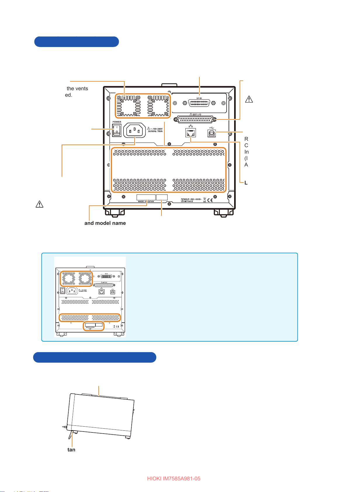
Rear of the instrument
Example: IM7585
Vents (p. 5)
Install so that the vents
are not covered.
Main power switch
(p. 24)
Power inlet (p. 20)
Connect the supplied power
cord.
(p. 6)
Serial number and model name
The 9-digit serial number indicates the year (rst two digits) and the
month of manufacture (next two digits). Do not remove this sticker as
the number is important.
Communication interface (option) (p. 235)
Optional interfaces can be installed.
Refer to the Communication Instruction Manual (Impedance Analyzer
Application Disc).
• Model Z3000 GP-IB Interface
• Model Z3001 RS-232C Interface
MAC address
EXT I/O Connector
(p. 199)
(p. 7)
USB cable connector
Refer to the
Communication
Instruction Manual
(Impedance Analyzer
Application Disc).
LAN connector
Refer to the
Communication
Instruction Manual
(Impedance Analyzer
Application Disc).
IM7580A, IM7581
In Models IM7580A and IM7581, the following are the
differences with Model IM7585.
• The position and shape of vents
• The position of the MAC address
• The position of the serial number and model name
Right side panel of the instrument
Handle
Used for carrying the instrument.
Example: IM7585
When setting up the stands
Open till the end without stopping in between.
Ensure that both stands are straight.
12
When closing the stands
Close till the end without stopping in between.
Stands
Enables the instrument to be tilted.
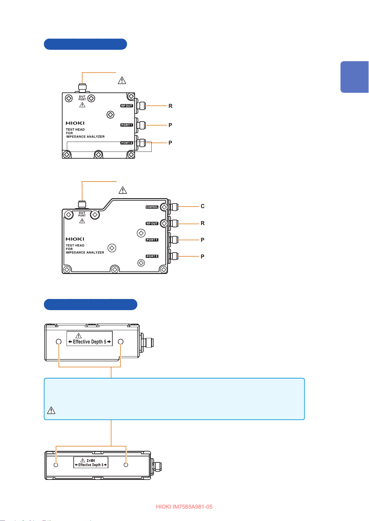
Side of the test head
HIOKI IM7585A981-05
IM7580A, IM7581
IM7583, IM7585, IM7587
Meauring terminal
(p. 6)
Measuring terminal
(p. 6)
Coaxial connectors
RF OUT
PORT1
PORT2
Coaxial connectors
Names and Functions of Parts
1
Overview
CONTROL
RF OUT
PORT1
PORT2
Bottom of the test head
IM7580A, IM7581
2×M4
Effective Depth 5
Threaded holes for xing the IM9200 Test Fixture Stand
These holes can also be used when xing a test head to an automated machine.
The depth of the threaded holes is 5 mm.
IM7583, IM7585, IM7587
Do not use screws of length exceeding M4 × 5 mm. Doing so may damage the device.
13
Screen Operations
HIOKI IM7585A981-05
1.3 Screen Operations
This instrument allows you to use a touch panel to set and change all measurement conditions.
Gently touch the key on the screen to select the item or numerical value set for that key.
In this manual, gently touching the screen is referred to as “press”.
CAUTION
Do not use excessive force on the touch panel, and do not use hard or sharp objects
that could damage the touch screen.
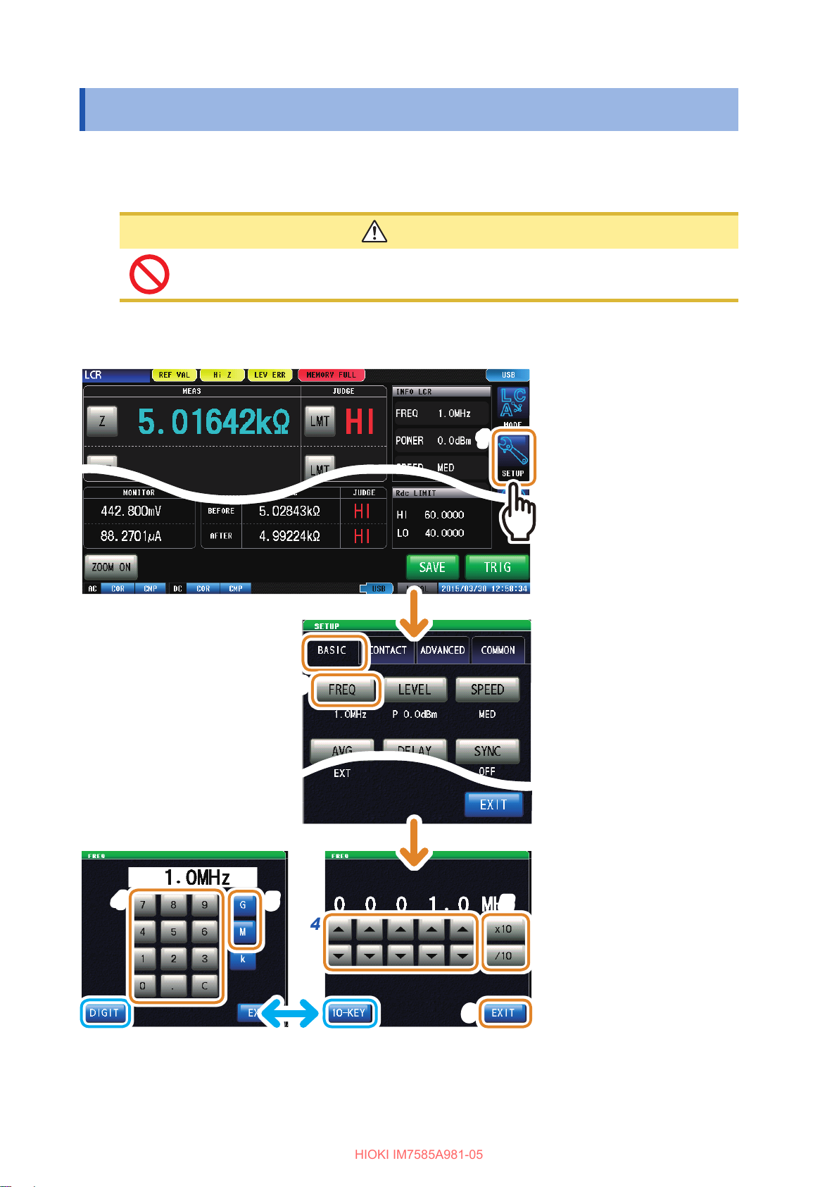
Example: Setting the measurement frequency in LCR mode
2
3
1
On LCR mode
1
screen, press
[SETUP] of the
menu key.
Press the [BASIC] tab.
2
Press [FREQ].
3
4
14
5
4
[DIGIT] (input with /), or [10-KEY] (input with the
numeric keypad).
6
5
Set the measurement
4
frequency with
the numeric keypad.
Press any unit key to
5
conrm the setting.
Press [EXIT] to close
6
the setting screen.
/,
or

Example: Moving the window
HIOKI IM7585A981-05
Screen Operations
You can move the window
by moving the top of the
window (green bar) while
pressing it.
1
Overview
15

Screen Operations
HIOKI IM7585A981-05
16

2
HIOKI IM7585A981-05
Read “Operating Precautions” (p. 5) before installing and connecting this instrument.
Refer to “Rack Mounting” (p. A7) for rack mounting.
Measurement Preparations
2.1 Connecting the Test Head
Connect the test head.
Refer to “5 Calibration and Compensation” (p. 141).
CAUTION
• If the instrument and the connectors of the test head are not correctly connected, the
instrument may get damaged or accurate measurements may not be possible.
• Tighten the connector with a torque of 0.56 Nm (recommended value). Tightening
the connector with a torque other than the recommended value may damage the
instrument or accurate measurements may not be possible.
2
Measurement Preparations
IMPORTANT
• Check that there are no problems with the connector before connecting the cable. If
there is a problem with the connector, you cannot perform accurate measurement due
to large measurement errors.
Refer to “Appx. 5 Maintenance of Coaxial Connector” (p. A6).
• The instrument, test head and measuring cables have been adjusted as a set before
shipment.
Connect the test head having the same serial number as the instrument with the
measuring cables supplied.
Example: IM7585
Rear of the instrument Rear of the test head
Serial No.
17

Connecting the Test Head
HIOKI IM7585A981-05
1
Check that the power switch of the instrument is turned off.
2
Connect CONTROL, RF OUT, PORT1, and PORT2 of the instrument to CONTROL, RF OUT,
PORT1, and PORT2 of the test head with the supplied measurement cable.
Example: IM7585
0.56 Nm
(recommended value)
If the specied torque is applied to the
torque wrench, it will rotate to the position
shown in the gure.
Do not rotate the cable when connecting the SMA connector of the cable to the
instrument and the test head. If the cable is rotated while connecting the connector, the
core wires of the connector or cable may get damaged. Rotate the nut of the connector
and connect.
18
Pre-Operation Inspection
HIOKI IM7585A981-05
2.2 Pre-Operation Inspection
Be sure to read “Operating Precautions” (p. 5) before use.
Before using the instrument for the rst time, verify that it operates normally to ensure that no
damage occurred during storage or shipping.
If you nd any damage, contact your authorized Hioki distributor or reseller.
Inspection of accessories and options
Inspection item Solution
Is the power cord insulation torn, or is any metal
exposed?
Is the insulation on the measurement cable torn, or is
any metal exposed?
Do not use the instrument if it is found to be damaged, as it
can result in electric shocks or short-circuit accidents.
Contact your authorized Hioki distributor or reseller.
If there is any damage, measurement values may not be
stable and measurement errors may occur.
We recommend using a new cable without any damage.
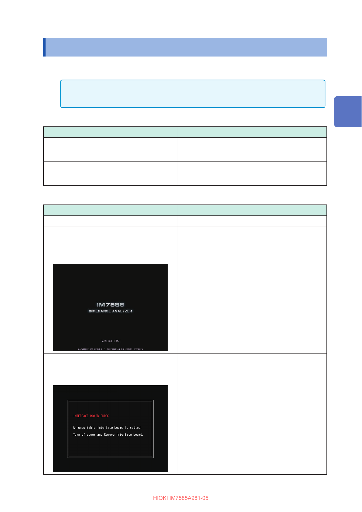
Instrument inspection
Inspection item Solution
Is the instrument damaged? If the instrument is damaged, request repairs.
Does the splash screen appear (Model no., version
no.) when the power is turned on?
Screen when the power is turned on
(Example: IM7585)
If the splash screen does not appear, the power cord may
be damaged, or the instrument may be damaged internally.
Request repairs.
2
Measurement Preparations
Is there an error displayed instead of the splash
screen?
Error display screen
If there is an error displayed, the instrument may be
damaged internally. Request repairs.
Refer to “Troubleshooting” (p. 305) and “Error Display”
(p. 310).
Example: An interface board that cannot be used is installed
(LAN board).
19

Connecting the Power Cord
HIOKI IM7585A981-05
2.3 Connecting the Power Cord
Please read “Before turning ON the power” (p. 6) and “Handling of cords and xtures” (p. 7)
before connecting the measurement cable or xture.
Connect the power cord to the power inlet on the instrument, and plug into an outlet.
Turn OFF the main power switch before disconnecting the power cord.
1
2
Check that the main power switch of the instrument is turned off.
Connect a power cord that is compatible with the line voltage to the power inlet on the
instrument (100 V to 240 V AC).
Rear (Example: IM7585)
3
Plug the other end of the power cord into an outlet.
20

Connecting a Measurement Cable/Fixture
HIOKI IM7585A981-05
2.4 Connecting a Measurement Cable/Fixture
Please read “Before turning ON the power” (p. 6) and “Handling of cords and xtures” (p. 7)
before connecting the measurement cable or xture.
Connect the measurement cables, or optional Hioki test xture to the measurement terminals.
Refer to “Options (Sold Separately)” (p. 2) for options.
Refer to the Instruction Manual of the xture for the operating details.
2
Note the following items when extending the distance between the test sample and
measuring terminals.
• Use 50 Ω coaxial cable for the measurement cable.
• Make the length of the cable as short as possible.
• Perform open/short/load calibration using the connecting terminal of the test sample.
Use the specied probes and xtures. When you make your own probe, it may not satisfy the
specications of this instrument.
Refer to “Options (Sold Separately)” (p. 2).
You will need:
• Test head × 1
• Model IM9200 Test Fixture Stand × 1
• Model IM9906 Adapter × 1
• 3.5 mm Connector torque wrench × 1 (This is not provided with the device.)
1
Metal ttings
Test head
Pull the metal ttings to the model IM9200 Test
1
Fixture Stand side.
Place the test head on the stand and tighten the knob.
2
Measurement Preparations
4
2
Model IM9906
3
Measuring terminal
Notch
3.5 mm connector
5
Model IM9200
nut
Place the notch of the model IM9906 Adapter parallel
3
to the metal ttings, then install onto the measurement
terminal of the test head.
At this time it is stopped temporarily. Position the notch of the
model IM9906 Adapter where the metal ttings can slide.
Fix the notch of model IM9906 adapter by sliding the
4
metal ttings.
Tighten the nut of the 3.5 mm connector by using a
5
torque wrench.
Recommended torque: 0.9 N·m
Tightening the nut until the handle of the wrench bends slightly is
sufcient. Do not over tighten.
21
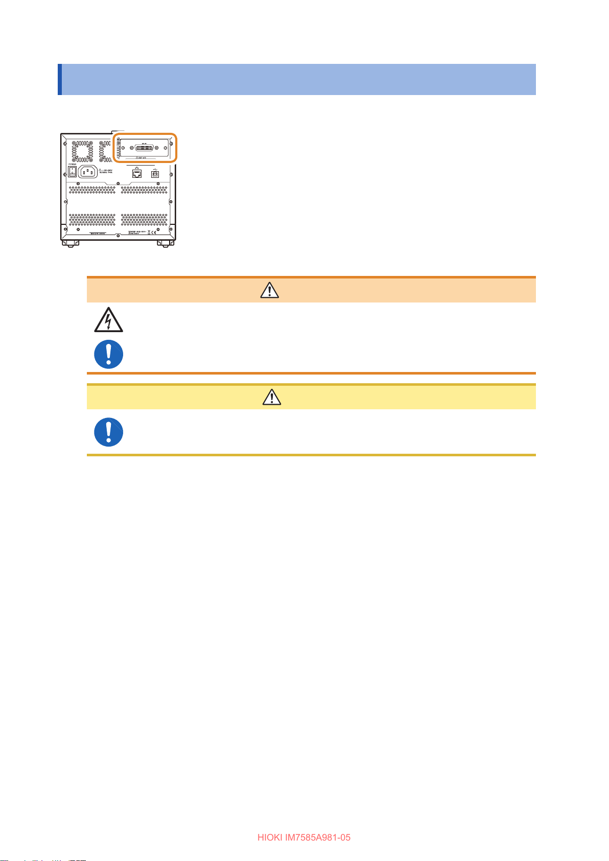
Connecting an Interface
HIOKI IM7585A981-05
2.5 Connecting an Interface
Rear (Example: IM7585)
To prevent instrument damage or electric shock, use only the screws (M3 × 6 mm)
shipped with the instrument for installing the interface.
If you have lost any screws or nd that any screws are damaged, please contact
your Hioki distributor for a replacement.
• Please read “Input modules (optional)” (p. 8) before connecting the
Interface.
• Read the Instruction Manual of the optional interface before installing or
replacing an optional interface or to use the instrument after removing
the interface.
• You can check the information of the interface installed in the
instrument on the screen.
Refer to “Setting the Interface” (p. 235) and “Checking the Instrument
Version” (p. 236).
WARNING
CAUTION
To connect or disconnect optional interfaces, hold the metal part. Touching the PCB with
bare hands could damage the instrument due to static electricity. (An antistatic wrist
strap is recommended when disconnecting the interface.)
22

You will need: A Phillips head screwdriver (No. 2)
HIOKI IM7585A981-05
Connecting an Interface
Installing the interface
Unplug the power cord of the instrument
1
from the wall outlet.
Disconnect the connection cords.
Rear
(M3 × 6 mm)
Use a Philips screwdriver
2
to remove the two xing
screws and detach the
blank panel.
Pay attention to the
3
orientation of the
(M3 × 6 mm)
Secure the interface in place by
4
tightening the two xing screws
with a Phillips head screwdriver.
interface and insert it
rmly into place.
Attaching the blank panel
Unplug the power cord of the instrument
1
from the wall outlet.
Disconnect the connection cords.
Rear
Attach the blank panel
2
and secure it in place by
tightening the two xing
screws with a Phillips
head screwdriver.
Attach the blank panel to use the instrument
after removing the interface.
Measuring without the blank panel will
prevent the instrument from performing to its
specications.
2
Measurement Preparations
Removing the interface
Unplug the power cord from the wall outlet and
perform the above procedure in reverse order to
remove the interface.
23

Turning the Power ON and OFF
HIOKI IM7585A981-05
2.6 Turning the Power ON and OFF
Connect the probe and test xture before turning the main power on.
Rear (Example: IM7585)
Power switch
(main power)
Turning the main power ON
Turn the main power switch ON ( | ).
The start button on the front will light up in green.
(Lights up in green)
Front (Example: IM7585)
Start button
Turning to the inactive state
Press the start button on the front for
approximately 1 second in the main power ON
state.
The color of the start button on the front changes
to red in the inactive state.
(Lights up in red)
• If the main power switch is turned OFF when
the instrument is in the inactive state, the
instrument will start up in the inactive state the
next time the main power switch is turned ON.
• To measure to the degree of accuracy
mentioned in the specications, allow a warm-
up time of 60 minutes or more after cancellation
of the inactive state.
Turning the main power OFF
Turn the main power switch OFF( ).
The start button on the front will turn off.
(Turns off)
• If the power supply is interrupted by a power
failure, etc, the instrument will return to the
measurement mode used before the power
failure.
• The instrument settings will be retained even if
the main power switch is turned OFF. (This is
backup function.)
Canceling the inactive state
To measure to the degree of accuracy mentioned
in the specications, allow a warm-up time of 60
minutes or more after cancellation of the inactive
state.
Press the start button on the front when the
instrument is in the inactive state.
The start button on the front will light up in green.
(Lights up in green)
What is inactive state?
The state in which the power supply of the instrument
is turned OFF.
(Only the circuit to turn ON the lamp of the start
button is active.)
If the instrument is not used for a long duration,
the internal battery must be charged. The required
charging time is at least 3 hours (recommended, 24
hours) after connecting the power supply and turning
ON the power of the instrument.
24

2.7 Select the Measurement Mode
HIOKI IM7585A981-05
Select any one of the following 3 measurement modes.
Press [MODE].
1
2
3
1
Select the measurement mode.
2
Press [EXIT].
3
Select the Measurement Mode
2
Measurement Preparations
[LCR]: LCR function
The LCR function allows you to measure the passive elements of
capacitors and coils with a single measurement condition.
This is suitable to make pass/fail judgments and classication on
production lines.
• Comparator function: Makes pass/fail judgments by determining whether
measurement values qualify as HI, IN, or LO.
• BIN function: Divides ranks up to 10 classications based on the
measurement values.
[ANALYZER]: Analyzer function
The analyzer function allows you to measure component and material
characteristics while sweeping the measurement frequency and signal
level.
This function provides equivalent circuit analysis based on the results of
frequency characteristics.
A pass/fail judgment based on a resonant frequency is available on
production lines of piezoelectric or similar elements.
• Area judgment: Judges whether the measurement values of the sweep
points are within the judgment area.
• Peak Judgment: Judges whether the peak value of the sweep result is
within the judgment area.
• Equivalent circuit analysis: Equivalent circuit models analysis for circuit
element components.
[CONTINUOUS]: Continuous measurement function
The continuous measurement function allows you to perform a series of
measurements with different conditions.
For example, Consecutive Ls measurement with 1 MHz of and Z
measurement with 100 MHz and its pass/fail judgment can be made.
LCR mode and ANALYZER mode measurement conditions can be
combined.
Up to 46 measurements (30 for LCR mode and 16 for ANALYZER mode)
can be performed continuously.
25

26
HIOKI IM7585A981-05

3
START
END
HIOKI IM7585A981-05
LCR Function
3.1 LCR Function
The LCR function allows you to measure the impedance, phase angle, and other items by applying
a signal of any frequency or level (RMS value) to the element you want to measure. This function is
suitable for evaluating the passive elements such as capacitors and coils.
It allows you to perform measurement while checking the measurement conditions on the
measurement screen. When the power is turned on again, the measurement screen will be
displayed in accordance with the measurement mode used before the power was turned off.
• Conditions set by the LCR function are not incorporated in the analyzer function.
• When a measurement value is outside the guaranteed accuracy range, REF VAL is displayed
in the error display area.
Check the guaranteed accuracy range. Consider measurement values outside the guaranteed
accuracy range as values for reference.
Refer to “Measurement range” (p. 277).
3.1.1 Flowchart
3
LCR Function
Set MODE to LCR
Necessary settings
Measurement parameter
settings
Basic measurement
settings
(FREQ,LEVEL,
SPEED,AVG,DELAY,
SYNC,TRIG)
Calibration/
Compensation
Contact check
settings
User-dened settings
Judgment settings
Common settings
Measurement
27

LCR Function
HIOKI IM7585A981-05
3.1.2 Screen map
Measurement
mode setting
screen (p. 25)
System settings
screen (p. 235)
Trigger
(p. 68)
Advanced settings screen (p. 33)
Compensation settings
screen
(p. 141)
[CAL] Calibration p. 145
[Rdc LIMIT] DC measurement limit value
[LENGTH]
[COMPEN] Compensation p. 155
[Rdc LIMIT] DC measurement limit value
[SCALE] Scaling p. 160
Electrical length
compensation
p. 152
p. 154
p. 159
Select an interface. (p. 235)
The version of the instrument can be veried. (p. 236)
Save
settings
screen
(p. 247)
[SETUP] Sets [SAVE] p. 247
[SAVE] Saves setting conditions p. 247
[LOAD] Reads setting conditions p. 265
[FORMAT] Formats USB ash drive
[DELETE]
[FOLDER]
[RENANE]
[SELECT]
[BACK]
Deletes les p. 273
Creates folders p. 270
Changes le names p. 271
Selects les p. 265
Displays the previous screen
p. 269
Self-checks (self-diagnosis) are enabled. (p. 237) The date and time can be set for the
28
instrument. (p. 242)

Advanced
HIOKI IM7585A981-05
settings
screen
(p. 37)
LCR Function
[FREQ] Measurement frequency p. 37
[LEVEL] Measurement signal level p. 38
[SPEED] Measurement speed p. 40
[AVG] Average p. 41
[DELAY] Trigger delay p. 34
[SYNC] Trigger synchronous output p. 35
[TRIG] Trigger p. 33
[TIMING] Contact check timing p. 171
[AC OUT] AC signal superimposition p. 173
[DC WAIT] Wait time prior to DC measurement p. 172
[WAVE] Number of DC
[AC WAIT] Wait time prior to AC measurement p. 172
[LIMIT] Judgment of DC measurement value p. 174
[ERR ABORT] Quit function in case of judgment error p. 174
[JDG EXEC] Judgment for reference values p. 174
[Hi Z] Hi Z reject function p. 176
[LEV CHECK] Monitoring function for detection level p. 177
[JUDGE] Judgment p. 44
[DIGIT]
[PARA ABS] Display of absolute value p. 180
[COM MEAS]
Number of display digits for each
parameter
Setting for communication command
:MEASURE?
“
samples
”
p. 173
p. 179
p. 181
3
LCR Function
[IO JUDGE] I/O output of judgment results p. 221
[IO TRIG] I/O trigger p. 219
[IO EOM] EOM output method p. 222
[MEMORY] Saving measurement results p. 262
[DISP] LCD display p. 184
[BEEP KEY] Beep sound p. 188
[COM FORM] Communication measurement data type p. 194
[KEYLOCK] Key lock p. 190
[WARM UP] Warm-up notication function p. 189
[PANEL] Panel loading and saving p. 227
[RESET]
Initializing p. 196
29

LCR Function
HIOKI IM7585A981-05
3.1.3 Measurement screen
Switches information to be displayed
on the measurement screen.
Sets measurement parameters. (p. 32)
Displays the measurement value.
Sets the upper and lower
limits. (p. 46)
The judgment result is
displayed. (p. 46)
[SET]
[COMP]
[BIN1] to
[BIN10]
Displays information
regarding LCR
measurement
Displays information on
comparator measurement
judgment standards.
Displays information on
BIN judgment standards.
Switches the display items
among measurement
conditions, upper and
lower limits of comparator
judgment or BIN judgment,
and others.
Displays measurement
conditions, upper and
lower limits of comparator
judgment or BIN judgment,
or others.
The setting window is
displayed by pressing
any measurement
condition area when
measurement conditions
are displayed.
Monitor values
are displayed.
Magnies the screen.
If [ZOOM OFF] is pressed,
the screen returns to the
normal display.
Rdc values are
displayed.
Saves the
measurement
data. (p. 263)
Sets the upper and lower
limit values of the DC
resistance. (p. 174)
The upper and lower limit
values of DC resistance are
displayed.
Inputs the trigger of an external
trigger. (p. 33)
30

3.1.4 Status and error display of this instrument
HIOKI IM7585A981-05
1 2 3 4
LCR Function
Displays the current measurement mode.
1
LCR function
Analyzer function
Continuous measurement
function
Displays error messages.
2
Outside guaranteed accuracy
Hi Z reject error
Error in detection level
Displays information saved in the internal
3
memory.
Number of memories saved
in the internal memory
8765
Displays the state of calibration or
5
compensation.
AC measurement
Calibration disabled
Calibration
Calibration enabled
Compensation
Compensation
DC measurement
Calibration
Compensation
disabled
Compensation
enabled
Calibration disabled
Calibration enabled
Compensation
disabled
Compensation
enabled
3
LCR Function
4
When the instrument
memory becomes full
Displays the type of interface that is
currently connected.
RS-232C
GP-IB
USB
LAN
Displays the connection status of the USB
6
ash drive.
(Blue)
(Red)
Displays the communication state.
7
Displays the date and time set for the instrument.
8
USB ash drive is
connected
USB ash drive is being
accessed
During communication control
Local
31

Setting Basic Settings of Measurement Conditions
HIOKI IM7585A981-05
3.2 Setting Basic Settings of Measurement Conditions
3.2.1 Setting Display Parameters
You can select up to 4 types from the 14 types of measurement parameters to display at any
arbitrary location.
The phase angle θ is shown in reference to impedance Z. When performing measurements using
admittance Y as the reference, the sign of the phase angle θ of impedance Z will be reversed.
Refer to “Appx. 1 Measurement Parameters and Calculation Formula” (p. A1).
Refer to “Appx. 3 Series Equivalent Circuit Mode and Parallel Equivalent Circuit Mode” (p. A4).
To display phase angles relative to admittance Y, use the scaling settings to multiply the impedance
phase angle θ by -1.
Refer to “5.4 Calculating Values (Scaling)” (p. 160)
1
Parameter Contents
[Z] Impedance (
[Y] Admittance (S)
[θ]
[Rs] Effective resistance = ESR (
[Rp] Effective resistance (
[Cs] Static capacitance (F) (series
[Cp] Static capacitance (F) (parallel
[D] Loss coefcient = tan
Impedance phase angle (°)
equivalent circuit)
equivalent circuit)
equivalent circuit)
equivalent circuit mode)
)
Ω
Ω
δ
) (series
Ω
) (parallel
1
Parameter Contents
[G] Conductance (S)
[X] Reactance (
[Ls] Inductance (H) (series equivalent
circuit)
[Lp] Inductance (H) (parallel equivalent
circuit mode)
[Q] Q factor
[B] Susceptance (S)
[OFF] No display
Press the parameter key that you want to set.
)
Ω
2
32
3
Select parameters.
2
Press [EXIT].
3

Setting Basic Settings of Measurement Conditions
HIOKI IM7585A981-05
3.2.2 Starting Measurement at Any Arbitrary Timing (Trigger)
Starts measurement at an arbitrary timing. A trigger is the function that controls the measurement
start timing with specic signals. The following items are the two types of trigger that can be set for
the instrument.
Internal trigger
External trigger
2
3
4
5
Measurement is repeated automatically. (Trigger signals are
automatically generated internally.)
Measurements are triggered by an external signal.
The trigger is controlled by the EXT I/O, interface, or manual setting
([TRIG]).
Press [SETUP].
1
1
Press the [BASIC] tab.
2
Press [TRIG].
3
Select the trigger type.
4
[INT] Internal trigger
[EXT] External trigger
3
LCR Function
Press [EXIT] to close the advanced settings
5
screen.
When EXT is selected
The following items are the three types of input method for a trigger.
Press [TRIG] on the screen to manually input a trigger.
1
Measurement is performed once.
If measurement takes a long time, [TRIG] may be displayed
as [STOP]. In this case, measurement can be suspended by
pressing [STOP].
Input via EXT I/O.
2
Measurement is performed once, each time a negative logic pulse signal is applied.
Refer to “8.1 External Input/Output Connector and Signals” (p. 199).
Input from interface.
3
Measurement is performed once when
Refer to Communication Commands included on Impedance Analyzer Application Disc.
*TRG
is transmitted.
33

Setting Basic Settings of Measurement Conditions
HIOKI IM7585A981-05
3.2.3 Setting the Delay Time from Trigger to Measurement Start (Trigger Delay)
The delay time period from input of the trigger signal to measurement (delay time) can be set.
With this function, it is possible to ensure that measurement is started after the connection condition
of the object to be tested and the test probe (xture) has stabilized.
Refer to “8.1 External Input/Output Connector and Signals” (p. 199).
Trigger delay: OFF Trigger delay: ON
TRIG
EOM
INDEX
Signal
Measurement Calculation
Even when the trigger delay is being used, the LED for indicating that measurement is in progress is lit.
TRIG
EOM
INDEX
Signal
Press [SETUP].
1
Measurement Calculation
Trigger delay
1
Press the [BASIC] tab.
2
2
Press [DELAY].
3
3
34
6
4
5
The numeric keypad can be
used for input.
Set the delay time with / or the numeric
4
keypad.
(With the numeric keypad, press [SET].)
Settable range 0.00000 s to 9.99999 s
Resolution 10 µs
[C]
Press [EXIT] to close the trigger delay setting
5
screen.
Press [EXIT] to close the advanced settings
6
screen.
The delay time becomes 0 s and this
function is disabled.

Setting Basic Settings of Measurement Conditions
HIOKI IM7585A981-05
3.2.4 Applying the Signal to the Sample during Measurement Only (Trigger Synchronous Output)
This function outputs the measurement signal after the trigger input and applies the signal only to
the sample during measurement.
You can also set a delay time to ensure that data is acquired after the sample stabilizes.
This reduces the generation of heat in the sample and decreases electrode wear.
Output of INDEX signals for switching to the next sample can be delayed till after the measurement
signal is completely OFF (0 V) after measurement has been completed (INDEX delay).
Trigger synchronous output: OFF Trigger synchronous output: ON
TRIG
EOM
INDEX
Signal
Measurement Calculation
2
3
1
TRIG
EOM
INDEX
Signal
Synchronous
signal wait
Press [SETUP].
1
Press the [BASIC] tab.
2
Press [SYNC].
3
3
LCR Function
INDEX delay
Measurement Calculation
4 5
9
Press [SYNC].
4
Select
5
output.
[OFF] Disables the trigger synchronous output.
[ON] Enables the trigger synchronous output.
Go to the next page.
[OFF] or [ON]
for the trigger synchronous
35

Setting Basic Settings of Measurement Conditions
HIOKI IM7585A981-05
Wait time
6
INDEX time
7
8
Use / to set the wait time (time to stabilize)
6
from the time a measurement signal has been
output by applying a trigger to the start of the
measurement.
(With the numeric keypad, press [SET].)
Settable range 0.00000 s to 9.99999 s
The numeric keypad can
be used for input.
7
8
9
• When the trigger synchronous output function is set to [ON], the measurement time increases due to
the addition of a wait time between output of the measurement signal and data acquisition.
Refer to “(3) Measurement Time” (p. 283).
• If a measurement condition is changed when the trigger synchronous output function is set to [ON], a
measurement signal of the set level may be output momentarily.
• The measurement signal is output when the trigger signal is input and stops after measurement ends.
• In CONTINUOUS measurement mode, the measurement condition is set as the setting of the initial
pulse after measurement of the last panel is completed.
If the trigger synchronous function is set to [ON] for the initial panel, the measurement signal stops.
[C]
Set the INDEX delay time.
(With the numeric keypad, press [SET].)
Settable range 0.00000 s to 0.10000 s
Press [EXIT] to close the trigger synchronous
output setting screen.
Press [EXIT] to close the advanced settings
screen.
Sets to the default value.
(The time is set to 0.001 s.)
Trigger delay: ON Trigger synchronous output: ON
TRIG
EOM
INDEX
Signal
Trigger delay Synchronous signal wait INDEX delay
Measurement Calculation
36

Setting Basic Settings of Measurement Conditions
HIOKI IM7585A981-05
3.2.5 Setting the Measurement Frequency
Sets the frequency of the signal applied to the test sample. The measurement value of the
measurement frequency level may change according to the sample tested.
Press [SETUP].
1
1
Press the [BASIC] tab.
2
2
Press [FREQ].
3
6
3
3
LCR Function
When setting with / (each digit)
4
5
The input method can be switched
between [DIGIT] and [10-KEY].
To set the frequency with the
numeric keypad
4
5
Set the frequency with / or the numeric
4
keypad.
Settable range:
IM7580A 1.0000 MHz to 300.00 MHz
IM7581 100.00 kHz to 300.00 MHz
IM7583 1.0 MHz to 600.0 MHz
IM7585 1.0 MHz to 1.3000 GHz
IM7587 1.0 MHz to 3.0000 GHz
When setting with / (each digit)
Holding down / changes the value continuously.
[×10] Sets the measurement frequency to 10×.
[/10] Sets the measurement frequency to
1/10×.
To set the frequency with the numeric keypad
Changing the unit: G (giga)/M (mega)/k (kilo)
[C] Repeats the input.
• The unit keys are enabled if a numerical value is input.
• The frequency is set on when any unit key is pressed
• If the setting exceeds the maximum frequency: The
maximum frequency will be set automatically.
• If the setting is below the minimum frequency: The
minimum frequency will be set automatically.
Press [EXIT] to close the measurement frequency
5
setting screen.
Press [EXIT] to close the advanced settings
6
screen.
37

Setting Basic Settings of Measurement Conditions
HIOKI IM7585A981-05
3.2.6 Setting the Measurement Signal Level
Sets the measurement signal level.
The value of the measurement signal level may change based on the sample tested.
This instrument can set the test signal applied to the object to be tested using the following three
methods.
Power (P) mode
Voltage (V) mode
Current (I) mode
• The setting resolution of the signal level is always 0.1 dB irrespective of the setting signal
mode.
When the level is set in the voltage or current mode, the input values are automatically
converted to the setting value with a resolution of 0.1 dB.
• The measurement accuracy varies according to the measurement signal level.
Refer to “Measurement range” (p. 277).
Sets the measurement signal level with the power (dBm) at the DUT
port 50
Sets the measurement signal level with the voltage (V) when the
DUT port is open.
(value of dBm converted into V)
Sets the measurement signal level with the current (A) when the
DUT port is in a short circuit state.
(value of dBm converted into I)
terminal.
Ω
Press [SETUP].
1
1
2
4 5
3
8
Press the [BASIC] tab.
2
Press [LEVEL].
3
Press [P/V/I].
4
Select the signal setting mode.
5
[POWER] Sets with power (dBm).
[V] Sets with voltage (V).
[I] Sets with current (A).
Go to the next page.
38

Setting Basic Settings of Measurement Conditions
HIOKI IM7585A981-05
6
The numeric keypad can
be used for input.
7
Set the voltage or current with
6
keypad.
Measurement
signal mode
Power (P) mode IM7580A,
Voltage (V) mode IM7580A,
Current (I) mode IM7580A,
(With the numeric pad, press [dBm].)
Model Settable range
IM7581
IM7583,
IM7585,
IM7587
IM7581
IM7583,
IM7585,
IM7587
IM7581
IM7583,
IM7585,
IM7587
[C]
Repeats the input.
or the numeric
/
-40.0 dBm to +7.0 dBm
(Resolution: 0.1 dB)
-40.0 dBm to +1.0 dBm
(Resolution: 0.1 dB)
4 mV to 1001 mV
4 mV to 502 mV
0.09 mA to 20.02 mA
0.09 mA to 10.04 mA
3
LCR Function
Press [EXIT] to close the measurement signal level
7
setting screen.
Press [EXIT] to close the advanced settings
8
screen.
When a measurement value is outside the guaranteed accuracy range, REF VAL is displayed in
the error display area.
Check the guaranteed accuracy range and change the measurement conditions or consider the
measurement values as values for reference.
Refer to “Measurement range” (p. 277).
Relationship between the setting values of the measurement signal mode
The relations between the power mode value and the voltage mode value and between the power
mode value and the current mode value are expressed by the following formulas:
VW= × ×2 50( )Ω
DBM
= × ÷×
210 1000 50
10
IW= × ÷2 50( )Ω
DBM
= × ÷÷
210 1000 50
10
Ω
()
Ω
()
DBM
Voltage
:
V
Current
:
I
Power (dBm) settings value
:
39

Setting Basic Settings of Measurement Conditions
HIOKI IM7585A981-05
3.2.7 Setting the Measurement Speed
Changes the measurement time.
Setting the measurement speed to [FAST] enables high speed measurement. Setting to [SLOW2]
enables measurement with high accuracy.
• Perform calibration and compensation again if there is a change in the measurement speed.
Refer to “5 Calibration and Compensation” (p. 141).
• The measurement time varies with the measurement conditions.
Refer to “(3) Measurement Time” (p. 283).
Press [SETUP].
1
1
Press the [BASIC] tab.
2
2
4
3
5
6
Press [SPEED].
3
Select the measurement speed.
4
[FAST] Performs high-speed measurement.
[MED] Performs normal-speed measurement.
[SLOW] Increases measurement accuracy.
[SLOW2] Measurement accuracy is better than
SLOW.
Press [EXIT] to close the measurement speed
5
setting screen.
Press [EXIT] to close the advanced settings
6
screen.
40

Setting Basic Settings of Measurement Conditions
HIOKI IM7585A981-05
3.2.8 Display with Average Values (Average)
The measurement values can be averaged using the averaging function. The variations in the
displayed measurement values can be reduced with this function.
The measurement values are always the moving average from
Internal trigger
present to before the number of times of averaging.
(When the sample to be tested is changed, it takes time for the
values to stabilize and the results are reliable.)
External trigger
It is the arithmetic mean of the number of times of averaging from
the trigger input.
When averaging is executed 4 times, the number of measurements, measurement output points,
and measurement value calculation method during output are as follows.
Moving average
Measurement points
M1 M2 M3 M4 M5 M6
M1
1
Measurement output values
Time
M1+M2
2
M1+M2+M3
3
M7 M8 M9 M10
M4+M5+M6+M74M5+M6+M7+M84M6+M7+M8+M94M7+M8+M9+M10
M1+M2+M3+M44M2+M3+M4+M54M3+M4+M5+M6
3
LCR Function
4
4
Arithmetic mean
Measurement points
M1 M2 M3 M4 M5 M6 M7 M8 M9
M5+M6+M7+M8
4
Measurement output values
Time
M1+M2+M3+M4
4
M10
41

Setting Basic Settings of Measurement Conditions
HIOKI IM7585A981-05
1
2
3
6
4
Press [SETUP].
1
Press the [BASIC] tab.
2
Press [AVG].
3
/ to enter the averaging number of times.
Use
4
Settable range 1 to 256 times
5
[C] Setting is turned OFF.
Press [EXIT] to close the average setting screen.
5
Press [EXIT] to close the advanced settings
6
screen.
42

Judging Measurement Results
HIOKI IM7585A981-05
3.3 Judging Measurement Results
The judgment results are displayed after the measurement results are compared to an arbitrarily
set reference. This function is useful for processes such as shipping inspection.
This includes the comparator function to make pass/fail judgments (HI/IN/LO) of measurement
values with one judgment standard, and the BIN function to classify (rank) measurement values
based on several judgment standards (up to 10).
L_COMP.png
3
LCR Function
One of the following 3 judgment methods can be used.
Setting the upper and lower limit values (ABS) (p. 48)
Upper limit
Lower limit
Percent (%) setting (p. 49)
Upper limit value [%]
Reference value
Lower limit value [%]
HI
IN
LO
HI
IN
IN
Setting the upper limit and lower limit values for the
measurement parameters.
The measurement values display the measurement parameter
values without any changes.
Enter reference values and set the difference between the upper
limit and the reference value, and between the lower limit
and the reference value as a ratio (percentage) relative to the
reference value.
The measurement values display the measurement parameter
values without any changes.
LO
Deviation percent (∆%)*2 setting (p. 51)
Upper limit value
[∆%]
Reference value
Lower limit value
[∆%]
HI
IN
IN
LO
Enter reference values and set the difference between the upper
limit and the reference value, and between the lower limit
and the reference value as a ratio (percentage) relative to the
reference value.
The measurement values display the deviations (∆%) from the
reference value.
*1
*1
*1 The following formula is used to calculate the comparison upper limit value and comparison lower limit
value. (For the comparison lower limit value, if a value that is lower compared to the reference value is
set, a minus (-) sign is required for the percentage setting value.)
Percentage setting value
Upper limit comparison value (Lower limit comparison value) = reference value + |reference value| ×
100
43

Judging Measurement Results
HIOKI IM7585A981-05
*2 The ∆% value is calculated using the following formula:
measurement value - reference value
∆% = × 100
| reference value|
3.3.1 Setting the Judgment Mode
Judgment results can be checked by acquiring the results of beep sounds, screen display, I/O output, and
communication commands.
Press [SETUP].
1
1
Press the [ADVANCED] tab.
2
2
Press [JUDGE].
3
3
4
5 6
10
7 8
9
Select the judgment mode.
4
[OFF] Disables the comparator and BIN function.
[COMP] Enables comparator judgment. (p. 46)
[BIN] Enables BIN judgment. (p. 53)
When a measurement value is outside the
5
guaranteed accuracy range, set the method to
judge the measurement value.
Judges the measurement value even when
[DO]
[NOT]
Sets the beep sounds for judgment results.
6
[OFF] Beeps are disabled.
the measurement values are outside the
guaranteed accuracy range.
Outputs an error for HI judgment when
a measurement value is outside the
guaranteed accuracy range.
44
[IN] Beeps if all the judgment results are IN.
[NG]
Set the beep tone with /.
7
Settable range 0 to 14
Beeps even if one of the judgment results
is LO or HI.

Judging Measurement Results
HIOKI IM7585A981-05
Set the beep volume with /.
8
Settable range 1 to 3
Press [EXIT] to close the judgment settings
9
screen.
Press [EXIT] to close the advanced settings
10
screen.
3
LCR Function
45

Judging Measurement Results
HIOKI IM7585A981-05
3.3.2 Judging with Upper and Lower Limit Values (Comparator Judgment Mode)
This mode judges if the measurement results are within the specied range.
The comparator judgment allows you to do the following things.
• Preset a judgment reference with a reference value or upper and lower limit values, and display
the judgment result as HI (higher than the upper limit value), IN (within the range set for the upper
and lower limit values), or LO (lower than the lower limit value).
• Output the judgment results to an external device (via the EXT I/O connector).
• Judges up to four parameters with different settings.
• Beeps to notify judgment results.
Refer to “3.3.1 Setting the Judgment Mode” (p. 44).
Measurement value > upper limit
HI
Upper limit value ≥ measurement value ≥
IN
lower limit value
Comparator judgment order
Judgment
order
• When the measurement value is MEAS ERR
1
2
3
4 In case of other than 1, 2 or 3 IN
• Outside the guaranteed accuracy range (Judgment for a value
outside the guaranteed accuracy range is [NOT])
When judging if the measurement value is higher than the lower limit
value, and the judgment is Fail.
When judging if the measurement value is lower than the upper limit
value, and the judgment is Fail.
Measurement value < lower limit
LO
If reference standards have not been set
- - -
Condition Judgment display
HI
LO
HI
46
• If measurement values are outside the guaranteed accuracy range (REF VAL), judgment is
performed in order of judgment when the setting of [JUDGE EXEC] is [DO]. If [NOT], judgment is
not performed and HI judgment is returned.
• If you interchange the upper limit and lower limit values an error message will not be displayed
because the upper and lower limit values are not compared.

Judging Measurement Results
HIOKI IM7585A981-05
• A comparator judgment can be used even if only the upper or lower limit value has been set.
When only an upper limit value
has been set
HI
Upper limit value
IN
When only a lower limit value
has been set
IN
Lower limit value
LO
3
LCR Function
47

Judging Measurement Results
HIOKI IM7585A981-05
Upper and lower limit values mode
This mode performs judgment with the upper and lower limits (ABS) that have been set.
Press [LMT].
1
1
Press [MODE].
2
32
Press [ABS].
3
Press [HI].
4
4
Changing the unit:
6
8
5
a/ f/ p/ n/ µ/ m/ None/ k/ M/ G
7
Set the upper limit value with the numeric pad and
5
press [SET].
Settable range -9.99999 G to 9.99999 G
[-] Enters a minus (-) sign.
3
] Increases the prex of the unit.
[×10
/103]
[
[OFF] No value is set.
[C] Repeats the input.
[CANCEL] Cancels the setting.
Press
6
7
8
[LO]
Set the lower limit value with the numeric pad and
press [SET].
Settable range -9.99999 G to 9.99999 G
Press [EXIT] to close the setting screen.
Decreases the prex of the unit.
.
48

Judging Measurement Results
HIOKI IM7585A981-05
Percent mode
Each of the differences between the upper limit and the reference value and between the lower
limit and the reference value is set as a ratio (percentage) relative to the reference value, and the
measurement values are judged whether they are within the range of the upper and lower limit values.
The set reference value and upper and lower limit values are common for percentage mode and deviation
percentage mode.
Press [LMT].
1
1
2
3
4
Changing the unit: a/ f/ p/ n/ µ/ m/ None/ k/ M/ G
5
Press [MODE].
2
Press [%].
3
Press [REF].
4
Set the reference value with the numeric pad and
5
press [SET].
Settable range -9.99999 G to 9.99999 G
[-] Enters a minus (-) sign.
3
] Increases the prex of the unit.
[×10
/103]
[
[OFF] No value is set.
[C] Repeats the input.
[CANCEL] Cancels the setting.
Decreases the prex of the unit.
3
LCR Function
6
Press [HI].
6
7
Upper limit comparison value (Lower limit comparison value)
Set the upper limit value with the numeric pad and
7
press [SET].
Sets the upper limit value as a percentage relative to the
reference value.
Settable range -999.999 % to +999.999 %
The actual internal operation consists of calculating the
comparison upper-limit value using the formula given below,
and comparing it to the measurement value to enable a
decision to be made.
= reference value + |reference value| ×
Go to the next page.
Percentage setting value
100
49

Judging Measurement Results
HIOKI IM7585A981-05
Press [LO].
8
8
10
9
Lower limit comparison value = reference value + |reference value|
Set the lower limit value with the numeric pad and
9
press [SET].
Set the lower limit value as a percentage relative to the
reference value.
Settable range -999.999% to 999.999%
The actual internal operation calculates the lower limit
comparison value with the following formula, and when a
value lower than the reference value is set, the minus (-)
sign is required for the percentage setting value.
Press [EXIT] to close the setting screen.
10
Percentage setting value
×
100
50

Judging Measurement Results
HIOKI IM7585A981-05
∆% mode
Each of the differences between the upper limit and the reference value and between the lower
limit and the reference value is set as a ratio (percentage) relative to the reference value, and the
measurement values are judged whether they are within the range between the upper and lower limit
values.
In the deviation percentage mode, the measurement values display the deviations (∆%) from the
reference value.
The ∆% value is calculated using the following formula:
measurement value - reference value
∆% =
The set reference value and upper and lower limit values are common for percentage mode and deviation
percentage mode.
|reference value|
× 100
Press [LMT].
1
1
3
LCR Function
2
3
Press [MODE].
2
Press [∆%].
3
51

Judging Measurement Results
HIOKI IM7585A981-05
Press [REF].
4
4
Changing the unit: a/ f/ p/ n/ µ/ m/ None/ k/ M/ G
5
7
6
9
8
10
Set the reference value with the numeric pad and
5
press [SET].
Settable range -9.99999 G to 9.99999 G
[-] Enters a minus (-) sign.
3
] Increases the prex of the unit.
[×10
/103]
[
[OFF] No value is set.
[C] Repeats the input.
[CANCEL] Cancels the setting.
Press [HI].
6
Set the upper limit value with the numeric pad and
7
press [SET].
Settable range -999.999% to 999.999%
Press [LO].
8
Set the lower limit value with the numeric pad and
9
press [SET].
Decreases the prex of the unit.
Settable range -999.999% to 999.999%
Press [EXIT] to close the setting screen.
10
52

Judging Measurement Results
HIOKI IM7585A981-05
3.3.3 Classifying Measurement Results (BIN Judgment)
Set the upper and lower limit values for 4 parameters and display up to 10 classications of
judgment results.
You can also output the judgment results to an external device.
Select the BIN judgment mode before setting the judgment conditions (p. 44).
In case of BIN judgment
BIN
When BIN is not set
- - -
OUT
When not matching any BIN
BIN judgment order: Starts with the judgment of the rst parameter for BIN1 and proceeds in
order to BIN10, as described below. The instrument will display the rst BIN number for which the
measurement value is judged to be within the set judgment standard.
If none of the BIN judgments are within the set judgment standard, [OUT] will be displayed.
Judgment
BIN number
BIN1
BIN2
BIN3
BIN10
First parameter
Judgment
OUT
Judgment
OUT
Judgment BIN3Judgment Judgment Judgment
Judgment
OUT
OUT
OUT
Second parameter
IN IN IN IN
OUT
IN IN IN IN
OUT
IN IN IN IN
IN IN IN IN
OUT OUT
Third parameter Fourth parameter
OUT
OUT
OUT
3
LCR Function
BIN judgment
results
BIN1Judgment Judgment Judgment
BIN2Judgment Judgment Judgment
BIN10Judgment Judgment Judgment
OUT
BIN1 BIN2 BIN3 BIN4 BIN5 BIN10
The measurement elements can be ranked by setting a series of judgment standards from severe
to lenient as shown in the following diagram.
• For more information about HI/IN/LO judgment
procedures, refer to p. 46.
• Set the upper/lower limit values to [OFF] for
BIN numbers not requiring BIN judgments.
• BIN judgment can be used even if only the
IN
Judgment
upper or lower limit value has been set. (See
the following gure.)
When only an upper
limit value has been set
When only a lower limit
value has been set
standard range
Upper limit
value
HI
IN
Lower
limit value
IN
LO
53

Judging Measurement Results
HIOKI IM7585A981-05
Upper and lower limit values mode
This mode performs judgment with the set upper and lower limits (ABS).
Press [LMT].
1
Press [Z].
2
1
The key display differs depending on the measurement
parameter.
Press [MODE].
3
2
Press [ABS].
4
4
3
Press [EXIT] to return to the BIN setting screen.
5
5
7
9
11
10
8
6
12
Display the BIN number to be set with / or by
6
scrolling.
Press the part corresponding to HI of the rst
7
parameter.
Use the numeric keypad to set the upper limit
8
value of the rst parameter and press [SET].
Settable range -9.99999 G to 9.99999 G
[-] Enters a minus (-) sign.
3
] Increases the prex of the unit.
[×10
/103]
[
[OFF] No value is set.
[C] Repeats the input.
[CANCEL] Cancels the setting.
Press the part corresponding to LO of the rst
9
parameter.
Use the numeric keypad to set the lower limit
10
value and press [SET].
Decreases the prex of the unit.
Changing the unit: a/ f/ p/ n/ µ/ m/ None/ k/ M/ G
54
Settable range -9.99999 G to 9.99999 G
The screen returns to the state in step 4.
Set the upper and lower limit values of the second
11
to fourth parameters, and press [SET].
Press [EXIT] to close the setting screen.
12

Judging Measurement Results
HIOKI IM7585A981-05
Percent mode
Each of the differences between the upper limit and the reference value and between the lower
limit and the reference value is set as a ratio (percentage) relative to the reference value, and the
measurement values are judged whether they are within the range between the upper and lower limit
values.
Press [LMT].
1
Press [Z].
2
The key display differs depending on the measurement
parameter.
Press [MODE].
3
Press [%].
4
The key display differs depending on the measurement
parameter.
2
3
1
4
3
LCR Function
6
10
12
8
5
7
9
Press [EXIT].
5
Press [REF].
6
Set the reference value with the numeric pad and
7
press [SET].
Settable range -9.99999 G to 9.99999 G
[-] Enters a minus (-) sign.
3
] Increases the prex of the unit.
[×10
/103]
[
[OFF] No value is set.
[C] Repeats the input.
[CANCEL] Cancels the setting.
Press [EXIT].
8
Display the BIN number to be set with / or by
9
scrolling.
Press the part corresponding to HI of the rst
10
parameter.
Decreases the prex of the unit.
Go to the next page.
15
55

Judging Measurement Results
HIOKI IM7585A981-05
11
14
13
Use the numeric keypad to set the upper limit
11
value of the rst parameter and press [SET].
Settable range -999.999% to 999.999%
Press the part corresponding to LO of the rst
12
parameter.
Use the numeric keypad to set the lower limit
13
value and press [SET].
Settable range -999.999% to 999.999%
The screen returns to the state in step 7.
Set the upper and lower limit values of the second
14
to fourth parameters, and press [SET].
Press [EXIT] to close the setting screen.
15
56

Judging Measurement Results
HIOKI IM7585A981-05
∆% mode
Each of the differences between the upper limit and the reference value and between the lower
limit and the reference value is set as a ratio (percentage) relative to the reference value, and the
measurement values are judged whether they are within the range between the upper and lower limit
values.
The set reference value and upper and lower limit values are common for percentage mode and deviation
percentage mode.
Press [LMT].
1
Press [Z].
1
2
2
The key display differs depending on the measurement
parameter.
Press [MODE].
3
3
LCR Function
6
8
3
4
5
7
Press [∆%].
4
The key display differs depending on the measurement
parameter.
Press [EXIT].
5
Press [REF].
6
Set the reference value with the numeric pad and
7
press [SET].
Settable range -9.99999 G to 9.99999 G
[-] Enters a minus (-) sign.
3
] Increases the prex of the unit.
[×10
/103]
[
[OFF] No value is set.
[C] Repeats the input.
[CANCEL] Cancels the setting.
Decreases the prex of the unit.
Press [EXIT].
8
Go to the next page.
57

Judging Measurement Results
HIOKI IM7585A981-05
10
12
11
14
9
15
Display the BIN number to be set with / or by
9
scrolling.
Press the part corresponding to HI of the rst
10
parameter.
Use the numeric keypad to set the upper limit
11
value of the rst parameter and press [SET].
Settable range -999.999% to 999.999%
13
Press the part corresponding to LO of the rst
12
parameter.
Use the numeric keypad to set the lower limit
13
value and press [SET].
Settable range -999.999% to 999.999%
The screen returns to the state in step 7.
Set the upper and lower limit values of the second
14
to fourth parameters, and press [SET].
Press [EXIT] to close the setting screen.
15
58

4
HIOKI IM7585A981-05
Analyzer Function
4.1 Analyzer Function
The analyzer function allows you to perform measurement while sweeping the measurement
frequency and signal level.
The measurement results can be displayed as a graph or numerical value. This function is used for
measuring frequency characteristics and level characteristics.
You can check the measurement result of each sweep point.
4
Analyzer Function
Displays the measurement results in a graph.
Use this function for measuring frequency characteristics and
level characteristics.
• Conditions set by the analyzer function are not transferred to the LCR function.
• When the power is turned on again, the display will be in accordance with the measurement
mode used before the power was turned off.
59

Analyzer Function
HIOKI IM7585A981-05
4.1.1 Flowchart
ANALYZER measurement
START
Set the MODE to ANALYZER
Measurement parameter settings
Sweep parameter settings
Other basic settings
(DELAY, SYNC, TRIG)
Settings of sweep points
Necessary settings
Calibration/Compensation
Graph display settings
Contact check settings
Judgment settings
Equivalent analysis circuit settings
Common Settings
Measurement
Read measurement value with CURSOR
User-dened settings
60
Read measurement value with SEARCH
END

Judgment settings
JUDGE ?
AREA PEAK
SEGMENT ?
ON
HIOKI IM7585A981-05
Analyzer Function
Judgment settings
Settings of JUDGE
Select target parameters
Settings of AREA Settings of PEAK area SPOT setting
Settings sweep points
OFF
AREA SPOT
JUDGE ?
PEAK
END
Settings of sweep points
Settings of SEGMENT
SEGMENT ?
ON
ON
4
Analyzer Function
Interval
QUICK EDIT
Sweep range number, sweep count,
basic measurement settings
Measurement settings for each point
Sweep range of segment, sweep
count, basic settings
END
Interval, basic measurement settings
61

Analyzer Function
HIOKI IM7585A981-05
4.1.2 Screen map
Measurement
mode setting
screen (p. 25)
System settings
screen (p. 235)
Trigger
(p. 68)
Advanced settings screen (p. 67)
Compensation
settings
screen
(p. 141)
[CAL] Calibration p. 145
[Rdc LIMIT]
[LENGTH]
[COMPEN] Compensation p. 155
[Rdc LIMIT] DC measurement limit value
[SCALE] Scaling p. 160
DC measurement limit value
Electrical length
compensation
p. 152
p. 154
p. 159
Select an interface.
The version of the instrument can be veried. (p. 236)
(p. 235)
Save
settings
screen
(p. 247)
[SETUP] Sets [SAVE] p. 247
[SAVE]
[LOAD] Reads setting conditions p. 265
[FORMAT]
[DELETE]
[FOLDER]
[RENANE]
[SELECT]
[BACK]
Saves the setting conditions
Formats USB ash drive p. 269
Deletes les p. 273
Creates folders p. 270
Changes le names p. 271
Selects les p. 265
Displays the previous screen
p. 247
Self-checks (self-diagnosis) are enabled. (p. 237) The date and time can be set for the
62
instrument. (p. 242)

Advanced
HIOKI IM7585A981-05
settings
screen
(p. 67)
Analyzer Function
[PARA] Parameter p. 67
[SOURCE] Sweep Parameter p. 72
[DELAY] Trigger delay p. 69
[SYNC] Trigger synchronous output p. 70
[TRIG] Trigger p. 68
[TIMING]
[Hi Z] Hi Z reject function p. 176
[LEV CHECK]
Settings of sweep points (p. 74)
Contact check (DC measurement)
Monitoring function for detection
level
p. 171
p. 177
4
Search function setting (p. 108)
Equivalent analysis circuit setting (p. 125)
[DIGIT]
[COM MEAS]
[IO JUDGE] I/O output of judgment result p. 221
[IO TRIG] I/O trigger p. 219
[IO EOM] EOM output method p. 222
[MEMORY] Saving measurement results p. 262
[DISP] LCD display p. 184
[BEEP KEY] Beep sound p. 188
[COM FORM]
[KEYLOCK] Key lock p. 190
[WARM UP] Warm-up notication function p. 189
[PANEL] Panel loading and saving p. 227
[RESET] Initializing p. 196
Number of display digits for each
parameter
Setting for communication
command “
Communication measurement
data type
:MEASURE?
”
p. 179
p. 181
p. 194
Analyzer Function
63

Analyzer Function
HIOKI IM7585A981-05
4.1.3 Measurement screen
Displays the measurement
value at the cursor position.
Executes a search. (p. 104)Sets the cursor. (p. 102)
Moves the cursor.
Moves the cursor to
[]
the left by ten points.
Moves the cursor to
[]
the left by one point.
Moves the cursor to
[]
the right by one point.
Moves the cursor
to the right by ten
[]
points.
Indicates the maximum
and minimum values of the
vertical axis of the graph.
Displays the Rdc value.
(p. 171)
[DISP] Selects the type of graph to display. (p. 65)
[GRAPH] Sets scaling of the graph, etc. (p. 92)
[CIRCUIT] Performs equivalent circuit analysis. (p. 126)
[SCALE] Performs auto-scaling for the vertical axis.
[SAVE]
[TRIG]
Saves the measurement data or screen.
This is displayed when a USB ash drive is connected.
Starts measurement.
This is displayed when the setting of trigger is [SEQ] or [STEP].
64

4.1.4 Types of graph
Sweep graph
All of the rst through fourth
parameters
Sweep graph 1
First parameter
Sweep graph 2
Second parameter
Sweep graph 3
Third parameter
Sweep graph 4
Fourth parameter
XY graph
X axis: rst parameter
Y axis: second parameter
XY graph 1
X axis: rst parameter
Y axis: second parameter
XY graph 2
X axis: third parameter
Y axis: fourth parameter
Sweep graph 1
First, and second parameters
Sweep graph 2
Third, and fourth parameters
XY graph 1
X axis: rst parameter
Y axis: second parameter
XY graph 2
X axis: third parameter
Y axis: fourth parameter
HIOKI IM7585A981-05
[DISP] on the measurement screen allows you to select the displayed graph.
[1 GRAPH] [4 GRAPHs]
Overall
comparator
judgment
result
[1 X-Y] [2 X-Ys]
Analyzer Function
Overall
comparator
judgment
result
[MULTI] [SPOT]
Overall
comparator
judgment
result
4
Analyzer Function
[NUMERIC] [PEAK] (p. 116)
Overall
comparator
judgment
result
65

Analyzer Function
HIOKI IM7585A981-05
4.1.5 Status and error display of this instrument
1 2 3 4
8765
Displays the current measurement mode.
1
LCR function
Analyzer function
Continuous measurement
function
Displays error messages.
2
Outside guaranteed accuracy
Hi Z reject error
Error in detection level
Displays information saved in the internal
3
memory.
Number of memories saved
in the internal memory
When the instrument
memory becomes full
Displays the state of calibration/
5
compensation.
AC measurement
Calibration disabled
Calibration
Calibration enabled
Compensation
Compensation
DC measurement
Calibration
Compensation
Displays the connection status of the USB
6
ash drive.
disabled
Compensation
enabled
Calibration disabled
Calibration enabled
Compensation
disabled
Compensation
enabled
Displays the type of interface that is
4
currently connected.
66
RS-232C
GP-IB
USB
LAN
(Blue)
(Red)
Displays the communication state.
7
Displays the date and time set for the instrument.
8
USB ash drive is
connected
USB ash drive is being
accessed
During communication control
Local

Setting Basic Settings of Measurement
First parameter
Second parameter
Fourth parameter
Third parameter
HIOKI IM7585A981-05
4.2 Setting Basic Settings of Measurement
4.2.1 Setting the Measurement Parameters
Select measurement display parameters.
ANALYZER mode allows four types of parameter measurements; rst to fourth parameters.
To display phase angles relative to admittance Y, use the scaling settings to multiply the impedance
phase angle θ by -1.
Refer to “5.4 Calculating Values (Scaling)” (p. 160)
Parameter Contents
[Z] Impedance (
[Y] Admittance (S)
[θ]
[Rs] Effective resistance = ESR (
[Rp] Effective resistance (
[Cs] Static capacitance (F) (series
[Cp] Static capacitance (F) (parallel
[D] Loss coefcient = tan
Impedance phase angle (°)
equivalent circuit)
equivalent circuit)
equivalent circuit)
equivalent circuit mode)
)
Ω
Ω
δ
1
) (series
Ω
) (parallel
1
2
Parameter Contents
[G] Conductance (S)
[X] Reactance (
[Ls] Inductance (H) (series equivalent
circuit)
[Lp] Inductance (H) (parallel equivalent
circuit mode)
[Q] Q factor
[B] Susceptance (S)
[V] monitor voltage (V)
[I] monitor current (A)
[OFF] No display
Press [SETUP].
Press the [SWEEP] tab.
)
Ω
4
Analyzer Function
3
4
2
5
Press [PARA].
3
Press the parameter key that you want to set.
4
Set [PARA1] to [Rs] (effective resistance
in series equivalent circuit mode = ESR
[
]) and [PARA2] to [X] (reactance [Ω]).
[COLE-COLE]
[GB-CURVE]
Press [EXIT] to close the setting screen.
5
Ω
Reverse the Y-axis. Set X-Y display autoscaling to [SAME].
Also [PARA3] and [PARA4] can be set.
Set [PARA1] to [G] (conductance [S])
and [PARA2] to [B] (susceptance [S]).
Set X-Y display auto-scaling to [SAME].
Also [PARA3] and [PARA4] can be set.
67

Setting Basic Settings of Measurement
HIOKI IM7585A981-05
4.2.2 Starting Measurement at Any Arbitrary Timing (Trigger)
Sets the triggers. The following items are the three types of trigger that can be set for the
instrument.
Refer to Step 4 for details on each trigger.
• Sequential sweep
• Repeat sweep
• Step sweep
The trigger setting that is set here differs from the trigger setting of LCR mode.
(It does not impact the trigger setting of LCR mode.)
Press [SETUP].
1
2
4
3
1
5
Press the [SWEEP] tab.
2
Press [TRIG].
3
Select the trigger type.
4
Performs a sequential sweep.
[SEQ]
[REPEAT]
[STEP]
Press [EXIT] to close the setting screen.
5
When an external trigger is input, sweep
measurement is performed only once.
Performs repeated sweeps.
Performs repeated sweeps with an internal
trigger.
Performs a step sweep.
When an external trigger is input,
measurement is performed at the current
measurement point and then the process
moves to the next measurement point.
When trigger is set to [SEQ] or [STEP]
68
• [TRIG] is displayed on the measurement screen.
• Each time you press [TRIG], a sequential sweep or
step sweep is performed.

Setting Basic Settings of Measurement
HIOKI IM7585A981-05
4.2.3 Setting the Delay Time from Trigger to Measurement Start (Trigger Delay)
Set the delay time from when a trigger is input until measurement starts.
Trigger delay: OFF Trigger delay: ON
――― ―
TRIG
―――
EOM
―― ―― ―
INDEX
Signal
External trigger
Measurement Calculation
Measurement of
sweep point 1
Measurement of
sweep point 2
――― ―
TRIG
―――
EOM
―― ―― ―
INDEX
Signal
Press [SETUP].
1
Trigger delay
Measurement of
sweep point 3
Measurement Calculation
: Trigger delay
: Point delay
Measurement of
the last sweep
point
Measurement complete
4
Analyzer Function
2
1
3
4
5
The numeric keypad can be
used for input.
Press the [SWEEP] tab.
2
Press [DELAY].
3
Set the delay time with / or with the numeric
4
keypad.
(With the numeric keypad, press [SET].)
Settable range 0.00000 s to 9.99999 s with resolution 10
ms
[C]
Press [EXIT] to close the setting screen.
5
• Disables this function.
• The set time is set to 0 s.
When a trigger delay is set, the LED for indicating that measurement is in progress is lit from the time a
trigger is input until the measurement ends.
69

Setting Basic Settings of Measurement
HIOKI IM7585A981-05
4.2.4 Applying the Signal to the Sample during Measurement Only (Trigger Synchronous Output)
This function enables the measurement signal to be output for only the initial sweep point after
measurement is triggered, so that the signal is applied to the sample during measurement only. You
can also set a delay time to ensure that data is acquired after the sample stabilizes.
This reduces the generation of heat in the sample and decreases electrode wear.
Trigger synchronous output: OFF Trigger synchronous output: ON
――― ―
TRIG
―――
EOM
―― ―― ―
INDEX
――― ―
TRIG
―――
EOM
―― ―― ―
INDEX
Signal
2
4 5
Measurement Calculation
1
3
Signal
Synchronous
signal wait
Press [SETUP].
1
Press the [SWEEP] tab.
2
Press [SYNC].
3
Press [SYNC].
4
INDEX delay
Measurement Calculation
70
Select
5
output.
[OFF] Disables the trigger synchronous output.
[ON] Enables the trigger synchronous output.
Go to the next page.
[OFF] or [ON]
for the trigger synchronous

6
HIOKI IM7585A981-05
Wait time
Setting Basic Settings of Measurement
Use / or the numeric keypad to set the
6
wait time (time to stabilize) from the time a
measurement signal has been output by applying
a trigger to the start of the next measurement.
(With the numeric keypad, press [SET].)
INDEX time
7
8
The numeric keypad can be
used for input.
• When the trigger synchronous output function is set to [ON], the measurement time will increase due
to the incorporation of a wait time between output of the measurement signal and data acquisition.
Refer to “(3) Measurement Time” (p. 283).
• When the trigger synchronous output function is set to [ON], the set level may be output momentarily
if a measurement condition is changed.
• The measurement signal is output when the trigger signal is input and stops after measurement ends.
• In CONTINUOUS measurement mode, the initial pulse is set after measurement of the last panel
ends.
If the trigger synchronous function is set to [ON] for the initial panel, the measurement signal stops.
Settable range 0.00000 s to 9.99999 s
[C]
Set the INDEX delay time.
7
(With the numeric keypad, press [SET].)
Settable range 0.00000 s to 0.10000 s
Press [EXIT] to close the trigger synchronous
8
output setting screen.
Press [EXIT] to close the setting screen.
9
Sets to the default value.
(The time is set to 0.001 s.)
4
Analyzer Function
71

Setting Basic Settings of Measurement
HIOKI IM7585A981-05
4.2.5 Setting the Sweep Parameter
Select sweep parameters. There are four types of parameters that can be set: frequency,
measurement signal level (power [P], voltage [V], and current [A]).
CAUTION
Do not switch between P, V, and I while the test sample is still connected to the
measurement terminals as this may damage the test sample.
• When the sweep parameter is changed, the comparator setting and sweep points are
initialized. Compensation is also disabled. Perform calibration and compensation once again.
• When performing equivalent circuit analysis, set the sweep parameter to the frequency sweep.
(p. 125)
2
3
4
1
5
Press [SETUP].
1
Press the [SWEEP] tab.
2
Press [SOURCE].
3
Select the sweep parameter.
4
[FREQ] Performs the frequency sweep.
[POWER]
[V]
[I]
Press [EXIT] to close the setting screen.
5
Performs measurement signal level (power
[P]) sweep.
Performs measurement signal level (voltage
[V]) sweep.
Performs measurement signal level (current
[A]) sweep.
72

4.3 Sweep measurement
HIOKI IM7585A981-05
Sets the sweep range and sweep points, and performs sweep measurement.
Types of sweep range
Sweep measurement
START-STOP
Sets the start value and end value of the sweep.
Each sweep point is automatically calculated
from the number of sweep points.
Start value End value
Number of sweep points
CENTER-SPAN
Sets the center value of the sweep range and
the sweep width.
Each sweep point is automatically calculated
from the number of sweep points.
Center value
Sweep width
START-STEP
Sets the start value of the sweep and the step
width of sweep points.
Each sweep point is automatically calculated
from the number of sweep points.
Start value
Step width
INTVL MEAS
Fixes the sweep parameter and performs
measurement at a set time interval.
Time interval
Time
Number of sweep points
4
Analyzer Function
73

Sweep measurement
HIOKI IM7585A981-05
4.3.1 Setting the Sweep Method
Select the sweep method.
Normal sweep
Normal interval sweep
(p. 81)
Segment sweep
Segment interval sweep
(p. 84)
What is a segment?
A segment refers to one block for which individual settings such as the sweep range, number of sweep
points, and measurement signal level can be set.
2
Sets the sweep range and number of sweep points, and performs
measurement.
(It is also possible to x the sweep parameter and perform “interval
measurement”, which is measurement at a set time intervals.)
Divides the sweep range into ranges called “segments” and performs
sweep measurement.
(The sweep range, sweep points, and measurement conditions can
be set for each segment. In addition, it is also possible to x the
sweep parameter and perform “interval measurement”, which is
measurement at a set time interval.)
Press [SETUP].
1
1
Press the [LIST] tab.
2
Press [SEGMENT].
3
3
Select the method of sweep.
4
4
5
[OFF] Normal sweep (normal interval sweep)
(p. 81)
[SEG ON] Segment sweep (p. 84)
[SEG INTVL] Segment interval sweep (p. 84)
Press [EXIT] to close the setting screen.
5
74

Setting example for normal sweep and segment sweep
HIOKI IM7585A981-05
Sweep measurement
Sweep setting
items
Sweep parameter Frequency Frequency Frequency Frequency
IM7580A,
Sweep
range
Number of sweep
Setting method for
IM7581
IM7583,
IM7585,
IM7587
points
sweep points
Measurement
signal type
Measurement
signal level
Average 5 times 10 times 3 times OFF
Measurement
speed
Point delay 0.0005 s 0.0005 s 0.0010 s 0.0000 s
Normal sweep Segment sweep
Segment Segment 1 Segment 2 Segment 3
1.0000 MHz to
300.00 MHz
1.0 MHz to
1.0000 GHz
801 points 201 points 201 points 399 points
Log Log Log Linear
POWER POWER POWER POWER
0.0 dBm 0.0 dBm 1.0 dBm -1.0 dBm
FAST FAST MEDIUM SLOW
1.0000 MHz to
5.0000 MHz
1.0 MHz to 10.0 MHz
10.000 MHz to
50.000 MHz
20.0 MHz to
100.0 MHz
50.000 MHz to
300.00 MHz
100.0 MHz to
1.0000 GHz
4
Analyzer Function
Normal sweep
Segment sweep
Normal sweep range
Segment 1 Segment 2 Segment 3
75

Sweep measurement
HIOKI IM7585A981-05
4.3.2 Setting the Sweep Range
Set the sweep range.
• If the sweep parameter is V or I, [CENTER-SPAN] and [START-STEP] cannot be set.
• For segment sweep, only [START-STOP] and [INTVL MEAS] can be set.
• The sweep range settings differ depending on the sweep parameter ([SOURCE]) settings
(p. 77).
Example: For normal sweep, set [START-STOP] in the frequency sweep (with [SOURCE] set to
[FREQ]).
Press [SETUP].
1
1
2
3
4
5
* Each common numeric keypad
Changing the unit: G (giga)/M (mega)/k (kilo)
Press the [LIST] tab.
2
Press [QUICK EDIT].
3
Select [START-STOP].
4
Refer to “Types of sweep range” (p. 73).
5
(1) Press [START].
(2) Use the numeric keypad* to set the start
value of sweep and press [Hz].
(3) Press [STOP].
(4) Use the numeric keypad* to set the end
value of sweep and press [Hz].
[C] Repeats the input.
[CANCEL] Cancels the setting.
76
6
7
8
Press [NUM] to set the sweep points.
6
Press [LOG] to set log calculation for sweep
7
points.
Press [SET] to conrm the setting.
8

Sweep range list
HIOKI IM7585A981-05
Sweep measurement
Setting
of sweep
parameters
([SOURCE])
Frequency
[FREQ]
Sweep range
setting
[START-STOP]
Contents of
setting
Start value of
sweep
[START]
End value of
sweep
[STOP]
Number of sweep
points
[NUM]
[LINEAR]
Settable range
IM7580A, IM7581 IM7583, IM7585, IM7587
IM7580A:
1.0000 MHz to 300.00 MHz
M7581:
100.00 kHz to 300.00 MHz
IM7580A:
1.0000 MHz to 300.00 MHz
IM7581:
100.00 kHz to 300.00 MHz
1 to 801
The sweep points are calculated linearly from the setting
values of [START], [STOP], and [NUM].
IM7583:
1.0 MHz to 600.0 MHz
IM7585:
1.0 MHz to 1.3000 GHz
IM7587:
1.0 MHz to 3.0000 GHz
IM7583:
1.0 MHz to 600.0 MHz
IM7585:
1.0 MHz to 1.3000 GHz
IM7587:
1.0 MHz to 3.0000 GHz
4
Analyzer Function
[CENTER-SPAN]
[LOG]
Center value of
sweep range
[CENTER]
Sweep width
[SPAN]
Number of sweep
points
[NUM]
The sweep points are calculated logarithmically from the
setting values of [START], [STOP], and [NUM].
IM7580A:
1.0000 MHz to 300.00 MHz
IM7581:
100.00 kHz to 300.00 MHz
* The setting range of [SPAN] varies according to the
frequency to be set.
IM7580A:
0 Hz to 300.00 MHz
IM7581:
0 Hz to 300.00 MHz
* The setting range varies based on the value set in
[CENTER].
1 to 801
IM7583:
1.0 MHz to 600.0 MHz
IM7585:
1.0 MHz to 1.3000 GHz
IM7587:
1.0MHz to 3.0000GHz
IM7583:
0 Hz to 600.0 MHz
IM7585:
0 Hz to 1.3000 GHz
IM7587:
0 MHz to 3.0000 GHz
77

Sweep measurement
HIOKI IM7585A981-05
Setting
of sweep
parameters
([SOURCE])
Frequency
[FREQ]
Sweep range
setting
[START-STEP]
Contents of
setting
Start value of
sweep
[START]
Step width of
sweep point
[STEP]
Number of sweep
points
[NUM]
Settable range
IM7580A, IM7581 IM7583, IM7585, IM7587
IM7580A:
1.0000 MHz to 300.00 MHz
IM7581:
100.00 kHz to 300.00 MHz
IM7580A:
0 Hz to 300.00 MHz
IM7581:
0 Hz to 300.00 MHz
* The setting range varies based on the value set in
[START] and [NUM].
1 to 801
IM7583:
1.0 MHz to 600.0 MHz
IM7585:
1.0 MHz to 1.3000 GHz
IM7587:
1.0 MHz to 3.0000 GHz
IM7583:
0 Hz to 600.0 MHz
IM7585:
0 Hz to 1.3000 GHz
IM7587:
0 MHz to 3.0000 GHz
Frequency
[FREQ]
[INTVL MEAS]
Start value of
sweep
[POINT]
Measurement time
interval
[INTERVAL]
Number of
measurements
[NUM]
IM7580A:
1.0000 MHz to 300.00 MHz
IM7581:
100.00 kHz to 300.00 MHz
0.00000 s to 1000.00 s
1 to 801
IM7583:
1.0 MHz to 600.0 MHz
IM7585:
1.0 MHz to 1.3000 GHz
IM7587:
1.0 MHz to 3.0000 GHz
78

Sweep measurement
HIOKI IM7585A981-05
Setting
of sweep
parameters
([SOURCE])
Power
[POWER]
Sweep range
setting
[START-STOP]
[CENTER-SPAN]
Contents of
setting
Start value of
sweep
[START]
End value of
sweep
[STOP]
Number of sweep
points
[NUM]
Center value of
sweep range
[CENTER]
Sweep width
[SPAN]
Number of sweep
points
[NUM]
Start value of
sweep
[START]
Settable range
IM7580A, IM7581 IM7583, IM7585, IM7587
-40.0 dBm to +7.0 dBm -40.0 dBm to +1.0 dBm
-40.0 dBm to +7.0 dBm -40.0 dBm to +1.0 dBm
1 to 801
* The setting method for sweep points is xed to
[LINEAR].
-40.0 dBm to +7.0 dBm -40.0 dBm to +1.0 dBm
0.0 dB to 1.0 dB
* The setting range varies based on the value set in
[CENTER].
1 to 801
-40.0 dBm to +7.0 dBm -40.0 dBm to +1.0 dBm
4
Analyzer Function
[START-STEP]
[INTVL MEAS]
Step width of
sweep point
[STEP]
Number of sweep
points
[NUM]
Start value of
sweep
[POINT]
Measurement time
interval
[INTERVAL]
Number of
measurements
[NUM]
0.1 dB to 1.0 dB
* The setting range varies based on the value set in
[START] and [NUM].
1 to 801
-40.0 dBm to +7.0 dBm -40.0 dBm to +1.0 dBm
0.00000 s to 1000.00 s
1 to 801
79

Sweep measurement
HIOKI IM7585A981-05
Setting
of sweep
parameters
([SOURCE])
Voltage [V]
Current [I]
Sweep range
setting
[START-STOP]
[INTVL MEAS]
Contents of
setting
Start value of
sweep
[START]
End value of
sweep
[STOP]
Number of sweep
points
[NUM]
Start value of
sweep
[POINT]
Measurement time
interval
[INTERVAL]
Number of
measurements
[NUM]
Start value of
sweep
[START]
Settable range
IM7580A, IM7581 IM7583, IM7585, IM7587
4 mV to 1001 mV 4 mV to 502 mV
4 mV to 1001 mV 4 mV to 502 mV
1 to 801
* The setting method for sweep points is xed to
[LINEAR].
4 mV to 1001 mV 4 mV to 502 mV
0.00000 s to 1000.00 s
1 to 801
* The measurement interval for INTERVAL measurement
is reected in the point delay time.
0.09 mA to 20.02 mA 0.09 mA to 10.04 mA
[START-STOP]
[INTVL MEAS]
End value of
sweep
[STOP]
Number of sweep
points
[NUM]
Start value of
sweep
[POINT]
Measurement time
interval
[INTERVAL]
Number of
measurements
[NUM]
0.09 mA to 20.02 mA 0.09 mA to 10.04 mA
1 to 801
* The setting method for sweep points is xed to
[LINEAR].
0.09 mA to 20.02 mA 0.09 mA to 10.04 mA
0.00000 s to 1000.00 s
1 to 801
80

4.3.3 Normal Sweep
HIOKI IM7585A981-05
Batch setting for normal sweep
1
Press [SETUP].
1
Sweep measurement
2
4
3
Press the [LIST] tab.
2
Press [QUICK EDIT].
3
Setting the sweep range.
4
Refer to “4.3.2 Setting the Sweep Range” (p. 76).
Batch setting for measurement conditions.
5
Refer to “4.4 Set Measurement Conditions for Sweep
Points” (p. 87).
4
Analyzer Function
5
6
Press [SET] to conrm the setting.
6
81

Sweep measurement
HIOKI IM7585A981-05
Adding sweep points
1
Press [SETUP].
1
4
5
2
6
3
Press the [LIST] tab.
2
Move the cursor to the point to be added in the list
3
of sweep points with / or by scrolling.
To add a sweep points on the next point in the selected row.
Press [ADD].
4
Set the measurement conditions for the sweep
5
points added.
Refer to “4.4 Set Measurement Conditions for Sweep
Points” (p. 87).
• [POINT] and [POINT DELAY] cannot be set for interval
measurements.
Press [SET] to conrm the setting.
6
Deleting sweep points
2
4
1
3
Press [SETUP].
1
Press the [LIST] tab.
2
Move the cursor to the point to be deleted in the
3
list of sweep points with / or by scrolling.
Press [DELETE].
4
82

Editing sweep points
HIOKI IM7585A981-05
1
Press [SETUP].
1
Sweep measurement
5
2
4
6
3
Press the [LIST] tab.
2
Move the cursor to the point to be edited with /
3
or by scrolling.
Press [EDIT].
4
Set the measurement conditions for the sweep
5
points to be edited.
Refer to “4.4 Set Measurement Conditions for Sweep
Points” (p. 87).
• The setting range ([POINT]) of the sweep parameter is a
value between the selected row and the next row.
• [POINT] and [POINT DELAY] cannot be set for interval
measurements.
Press [SET] to conrm the setting.
6
4
Analyzer Function
83

Sweep measurement
HIOKI IM7585A981-05
4.3.4 Segment Sweep and Segment Interval Sweep
Adding segments
Press [SETUP].
1
1
2
4
Deleting segments
1
3
Press the [LIST] tab.
2
Move the cursor to the point to be added with /
3
or by scrolling.
Add a segment on the next point in the selected row.
Press [ADD].
4
A segment is added with the default value.
Press [SETUP].
1
84
4
2
3
Press the [LIST] tab.
2
Move the cursor to the point to be deleted with
3
or by scrolling.
/
Press [DELETE].
4

Editing segments
HIOKI IM7585A981-05
1
Press [SETUP].
1
Sweep measurement
2
5
4
3
Press the [LIST] tab.
2
Move the cursor to the point to be edited with /
3
or by scrolling.
Press [EDIT].
4
Setting the sweep range.
5
Refer to “4.3.2 Setting the Sweep Range” (p. 76).
The setting of sweep range is xed to [START-STOP]
in segment sweep, and [INTVL MEAS] in segment
interval sweep.
4
Analyzer Function
6
7
Batch setting for measurement conditions.
6
Refer to “4.4 Set Measurement Conditions for Sweep
Points” (p. 87).
Press [SET] to conrm the setting.
7
85

Sweep measurement
HIOKI IM7585A981-05
Checking the set sweep points
1
Press [SETUP].
1
2
3
Press the [LIST] tab.
2
Press [VIEW POINT].
3
The set sweep points can be checked.
86

Set Measurement Conditions for Sweep Points
HIOKI IM7585A981-05
4.4 Set Measurement Conditions for Sweep Points
Sets the measurement conditions for sweep points.
Setting is possible from the setting and editing of sweep points.
Refer to “4.3.3 Normal Sweep” (p. 81) and “4.3.4 Segment Sweep and Segment Interval Sweep” (p. 84).
4.4.1 Setting the Measurement Signal Frequency
Sets the measurement signal frequency.
When setting with / (each digit)
1
3
The input method can be switched
between [DIGIT] and [10-KEY].
To set the frequency with the
numeric keypad
1
2
Changing the unit: G (giga)/M (mega)/k (kilo)
Set the frequency with / or the numeric
1
keypad.
Settable range:
IM7580A 1.0000 MHz to 300.00 MHz
IM7581 100.00 kHz to 300.00 MHz
IM7583 1.0 MHz to 600.0 MHz
IM7585 1.0 MHz to 1.3000 GHz
IM7587 1.0 MHz to 3.0000 GHz
When setting with / (each digit)
Holding down / changes the value continuously.
[×10] Sets the measurement frequency to 10×.
[/10] Sets the measurement frequency to
1/10×.
To set the frequency with the numeric keypad
[C] Repeats the input.
• The unit keys are enabled if a numerical value is input.
• The frequency is set on when any unit key is pressed.
• If the setting exceeds the maximum frequency: The
maximum frequency will be set automatically.
• If the setting is below the minimum frequency: The
minimum frequency will be set automatically.
Press [EXIT] to close the measurement frequency
2
setting screen.
4
Analyzer Function
Press [EXIT] to close the advanced settings
3
screen.
87

Set Measurement Conditions for Sweep Points
HIOKI IM7585A981-05
4.4.2 Setting the Measurement Signal Level
The value of the test signal level may change based on the sample tested.
CAUTION
Do not switch between P, V, or I while the test sample is still connected to the
measurement terminals as this may damage the test sample.
The following items are the three types of measurement signal levels that can be applied to the
object under test with this instrument.
Power (P) mode
Voltage (V) mode
Current (I) mode
• The setting resolution of the signal level is always 0.1 dB regardless of setting signal mode.
When the level is set in the voltage or current mode, input values are automatically converted to the
setting value with a resolution of 0.1 dB.
• The measurement accuracy varies according to the measurement signal level.
Refer to “Measurement range” (p. 277).
• For details on calculation, refer to “Relationship between the setting values of the measurement signal
mode” (p. 39).
• The measurement signal mode is common for all points.
• When the sweep parameter is POWER/ V/ I, the measurement signal mode cannot be changed.
Sets with the power (dBm) at the DUT port 50 Ω terminal.
Sets with the voltage (V) when the DUT port is open.
(value of dBm converted into V)
Sets with current (A) when the DUT port is in a short circuit state.
(value of dBm converted into I)
88

Set Measurement Conditions for Sweep Points
HIOKI IM7585A981-05
1 2
5
3
4
The numeric keypad can be
used for input.
Press [P/V/I].
1
Select the signal setting mode.
2
[POWER] Sets with power (dBm).
[V] Sets with voltage (V).
[I] Sets with current (A).
Set the voltage or current with / or the numeric
3
keypad. (With the numeric pad, press [dBm].)
Measurement
signal mode
Power (P) mode IM7580A,
Voltage (V)
mode
Model Settable range
-40.0 dBm to +7.0 dBm
IM7581
IM7583,
IM7585,
IM7587
IM7580A,
IM7581
IM7583,
IM7585,
IM7587
(Resolution: 0.1 dB)
-40.0 dBm to +1.0 dBm
(Resolution: 0.1 dB)
4 mV to 1001 mV
4 mV to 502 mV
4
Analyzer Function
Current (I) mode IM7580A,
IM7581
IM7583,
IM7585,
IM7587
[C] Repeats the input.
Press [EXIT] to close the measurement signal level
4
setting screen.
Press [EXIT] to close the advanced settings
5
screen.
When a measurement value is outside the guaranteed accuracy range, REF VAL is displayed in
the error display area.
In this case, the measurement signal level is considered to be low. Check the guaranteed
accuracy range and change the measurement conditions or consider the measurement values
as values for reference.
Refer to “Measurement range” (p. 277).
0.09 mA to 20.02 mA
0.09 mA to 10.04 mA
89

Set Measurement Conditions for Sweep Points
HIOKI IM7585A981-05
4.4.3 Setting the Measurement Speed
Changes the measurement time.
When the measurement speed is set to [SLOW] or [SLOW2], the measurement accuracy
improves.
• Perform calibration or compensation again if there is a change in the measurement speed.
Refer to “5 Calibration and Compensation” (p. 141).
• Measurement time varies with the measurement conditions.
Refer to “(3) Measurement Time” (p. 283).
Select the measurement speed.
1
1
[FAST] Performs high-speed measurement.
2
3
2
3
[MED] Performs normal-speed measurement.
[SLOW] Increases measurement accuracy.
[SLOW2] Measurement accuracy is better than
SLOW.
Press [EXIT] to close the measurement speed
setting screen.
Press [EXIT] to close the advanced settings
screen.
4.4.4 Displaying Average Values (Average)
The measurement values can be averaged using the averaging function. The variations in the
displayed measurement values can be reduced with this function.
• The measurement values are averaged by arithmetic averaging during analyzer measurement
irrespective of the trigger setting (p. 41).
• When averaging is enabled, the maximum, minimum, and peak values (local maximum and
local minimum values) during the search function operation use the averaged values.
90
1
2
Use / to enter the averaging number of times.
1
Settable range 1 to 256 times
[C] Setting is turned OFF.
Press [EXIT] to close the average setting screen.
2
Press [EXIT] to close the advanced settings
3
screen.

Set Measurement Conditions for Sweep Points
HIOKI IM7585A981-05
4.4.5 Setting the Delay Time for Each Sweep Point (Point Delay)
Sets the delay time for each sweep point in the point delay setting.
In sweep measurement, some measurement samples may require time for the measurement
value to stabilize due to a transient response. For such cases, set a point delay time.
Refer to “3.2.3 Setting the Delay Time from Trigger to Measurement Start (Trigger Delay)”
(p. 34).
For sequential sweep
External trigger
Measurement of
sweep point 1
Measurement of
sweep point 2
Measurement of
sweep point 3
For repeat sweep
Internal Trigger
Measurement of
sweep point 1
Measurement of
sweep point 2
Returns to the measurement of sweep point 1.
Measurement of
sweep point 3
For step sweep
External trigger External trigger External trigger
Measurement of
sweep point 1
Measurement of
sweep point 2
Measurement completeMeasurement complete
Measurement of
sweep point 3
Trigger delay
Point delay
Measurement of
the last sweep
point
Measurement complete
Measurement of
the last sweep
point
Measurement of
the last sweep
point
Measurement completeMeasurement complete
4
Analyzer Function
1
2
The numeric keypad can be
used for input.
Use / to enter the delay time.
1
(With the numeric keypad, press [SET].)
Settable range 0.00000 s to 9.99999 s
[C] Sets to the default value. (0.00000 s)
Press [EXIT] to close the setting screen.
2
Press [EXIT] to close the advanced settings
3
screen.
91

Setting the Graph Display Method
HIOKI IM7585A981-05
4.5 Setting the Graph Display Method
4.5.1 Setting the Horizontal Axis
Horizontal axis scale setting
Press [GRAPH].
1
1
32
4
How to check the set horizontal axis scale?
If the horizontal axis display scale is changed, the horizontal axis scale of the graph display screen
changes as shown in the gures below.
When the horizontal axis scale is set to linear
([LINEAR])
Press [SCALE].
2
Select the drawing type.
3
[LINEAR] Sets the horizontal axis to linear (linear axis).
[LOG] Sets the horizontal axis to log (logarithmic
axis).
Press [EXIT] to close the setting screen.
4
When the horizontal axis scale is set to log ([LOG])
92
 Loading...