

IM3523
HIOKI IM3570A983-08
IM3523A
IM3533
IM3533-01
IM3536
LCR METER
IM3570
Communication Instruction Manual
IM7580
IMPEDANCE ANALYZER
IM3590
CHEMICAL
IMPEDANCE ANALYZER
Dec. 2022 Revised edition 8
IM3570A983-08 22-12H
EN
[600329708]

HIOKI IM3570A983-08

Contents
Contents
HIOKI IM3570A983-08
i
1
Introduction.....................................................1
Safety Information ..........................................1
Chapter 1 Specifications 3
1.1 RS-232C Specifications ......................... 3
1.2 GP-IB Specifications ..............................4
1.3 USB Specifications ................................ 4
1.4 LAN Specifications ................................. 4
Chapter 2 Model IM3570/
IM3536
Connection and
Setting 5
2.1 Overview of Communication ..................5
2.2 RS-232C Connection and Settings ........ 7
2.3 GP-IB Connection and Settings ............. 9
2.4 USB Settings and Connection ............. 11
2.5 LAN Settings and Connection .............. 13
2.6 Remote Mode ...................................... 19
Chapter 3 Model IM3523/
IM3523A
Connection and
Setting 21
3.1 Overview of Communication ................21
3.2 USB Settings and Connection ............. 23
IM3570A983-08
Connecting the RS-232C Cable ..............7
Setting RS-232C ......................................8
Connecting the GP-IB Cable ...................9
Setting GP-IB ...........................................9
Setting USB ...........................................11
Connecting the USB Cable ....................12
LAN Settings ..........................................13
Connecting a LAN Cable .......................18
IM3523 ...................................................21
IM3523A ................................................22
Setting USB ...........................................23
Connecting the USB Cable ................... 24
3.3 GP-IB Connection and Settings
(IM3523 only, when connected to the
Z3000) ..................................................25
Connecting the GP-IB Cable ................. 25
Setting GP-IB ........................................ 25
3.4 RS-232C Connection and Settings
(IM3523 only, when connected to the
Z3001) ..................................................27
Connecting the RS-232C Cable ............ 27
Setting RS-232C ................................... 28
3.5 LAN Settings and Connection
(IM3523 needs to be connected to the
Z3002) ..................................................30
LAN Settings ......................................... 30
Connecting a LAN Cable ...................... 33
3.6 Remote Mode .......................................34
Chapter 4 Model IM3533/
IM3533-01/
IM3590 Connection and
Setting 35
4.1 Overview of Communication ................35
4.2 USB Settings and Connection ..............37
Setting USB .......................................... 37
Connecting the USB Cable ................... 38
4.3 GP-IB Connection and Settings
(when connected to the Z3000) ...........39
Connecting the GP-IB Cable ................. 39
Setting GP-IB ........................................ 39
4.4 RS-232C Connection and Settings
(when connected to the Z3001) ...........41
Connecting the RS-232C Cable ............ 41
Setting RS-232C ................................... 42
4.5 LAN Settings and Connection
(when connected to the Z3002) ...........43
LAN Settings ......................................... 43
Connecting a LAN Cable ...................... 48
4.6 Remote Mode .......................................49
2
3
4
5
6
7
8
9
10
11
12
Appendix
Index
索
引

ii
HIOKI IM3570A983-08
Contents
Chapter 5 Model IM7580 Connection and Setting 51
5.1 Overview of Communication ................51
5.2 USB Settings and Connection ..............53
Setting USB .......................................... 53
Connecting the USB Cable ................... 54
5.3 LAN Settings and Connection ..............55
LAN Settings ......................................... 55
Connecting a LAN Cable ...................... 60
5.4 GP-IB Connection and Settings
(when connected to the Z3000) ...........61
Connecting the GP-IB Cable ................. 61
Setting GP-IB ........................................ 61
5.5 RS-232C Connection and Settings
(when connected to the Z3001) ...........63
Connecting the RS-232C Cable ............ 63
Setting RS-232C ................................... 64
5.6 Remote Mode .......................................65
Appendix A 1
Appendix 1 Checking the USB Virtual
COM Port ................................. A 1
1
HIOKI IM3570A983-08
Introduction
This instruction manual provides details on the communication interfaces of the IM3523, IM3523A, IM3533,
IM3533-01, IM3536 LCR Meter, IM3570, IM7580 Impedance Analyzer and IM3590 Chemical Impedance Analyzer.
In this document, the “instrument” means the IM3523, IM3523A, IM3533, IM3533-01, IM3536, IM3570,
IM7580 and IM3590.
The latest edition of the instruction manual
The contents of this manual are subject to change, for example as a result of product
improvements or changes to specifications.
The latest edition can be downloaded from Hioki’s website.
https://www.hioki.com/global/support/download/
Product registration
Register your product in order to receive important product information.
https://www.hioki.com/global/support/myhioki/registration/
Safety Information
This manual contains information and warnings essential for safe operation of the instrument and for maintaining it in safe operating condition. Before using it, be sure to carefully read the following safety precautions.
Safety Symbols
The following symbols in this manual indicate the relative importance of cautions and warnings.
Indicates that incorrect operation presents a significant hazard that could result in serious injury or death to the user.
Indicates that incorrect operation presents a possibility of injury to the user or damage to
the product.
Advisory items related to performance or correct operation of the product.
Notation
Symbols in this manual
Indicates the prohibited action.
(Bold character)
(p. )
* Indicates that descriptive information is provided below.
[ ]
CURSOR
Windows
Dialogue Dialogue box represents a Windows dialog box.
Indicates the location of reference information.
Menus, commands, dialogs, buttons in a dialog, and other names on the screen and the keys are
indicated in brackets.
Bold characters within the text indicate operating key labels.
Unless otherwise specified, “Windows” represents Windows 7, Windows 8, or Windows 10.
2
HIOKI IM3570A983-08
Mouse Operation
Click: Press and quickly release the left button of the mouse.
Right-click: Press and quickly release the right button of the mouse.
Double click: Quickly click the left button of the mouse twice.
Drag:
While holding down the left button of the mouse, move the mouse and then release the left button
to deposit the chosen item in the desired position.
1.1 RS-232C Specifications
Control during Receiving
CA(RTS)
OFF
ON
25%
85%
Input Buffer
Usage
Amount
Buffer Space
75%
Send XOFF
Send XON
Control during Sending
HIOKI IM3570A983-08
Specifications Chapter 1
1.1 RS-232C Specifications
3
Transmission Method
Transmission Speed 9600 bps, 19200 bps, 38400 bps, 57600 bps
Data Bits 8 bits
Parity None
Stop bit 1 bits
Message terminator
(delimiter)
Flow control
Input voltage
Electrical
Specifications
level
Output voltage
level
Communication method: Full duplex
Synchronous method: Start-stop synchronization
CR+LF, CR
Hardware (RTS/CTS control), software (XON/XOFF control)
“Handshake (About Buffer Flow Control)” (p. 3)
IM7580: Software (XON/XOFF control only)
5 to 15 V ........ ON
-15 to -5 V ....... OFF
5 to 9 V .......... ON
-9 to -5 V ........ OFF
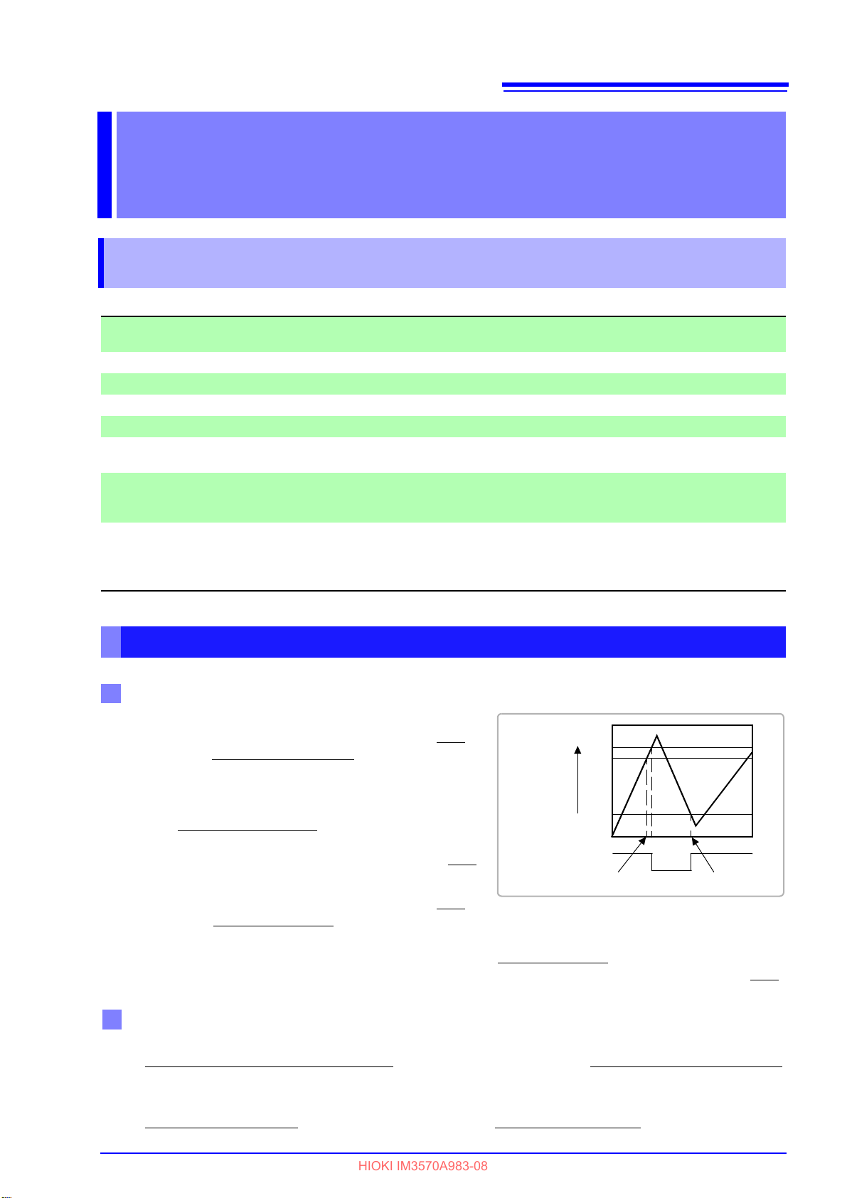
Handshake (About Buffer Flow Control)
When using hardware (RTS/CTS control):
• When the data in the receive buffer exceeds 85% of
the buffer, CA(RTS) is set to OFF
notified that there is not much space remaining in the
buffer.
• Processing of the data in the buffer continues, and
then CA(RTS) is set to ON
fied that there is sufficient remaining space in the buffer when the amount of data becomes less than 25%
When using software (XON/XOFF control):
• When the data in the receive buffer exceeds 75% of
the buffer, XOFF(13H) is sent
the buffer.
• Processing of the data in the buffer continues, and then XON(11H) is sent and the controller is notified
that there is sufficient remaining space in the buffer when the amount of data becomes less than 25%
and the controller is
and the controller is noti-
.
and the controller is notified that there is not much space remaining in
.
When using hardware (RTS/CTS control):
• When CB(CTS) is confirmed to be OFF, the sending of data is halted. When it is confirmed to be ON,
the sending of data is resumed.
When using software (XON/XOFF control):
• When XOFF is received, the sending of data is halted. When XON is received, the sending of data is
resumed.

4
HIOKI IM3570A983-08
1.2 GP-IB Specifications
1.2 GP-IB Specifications
SH1 Supports all source handshake functions.
AH1 Supports all acceptor handshake functions.
T6 Supports standard talker functions.
L4 Supports standard listener functions.
SR1 Supports all service request functions.
RL1 Supports all remote/local functions.
PP0 Parallel poll functions are not supported.
DC1 Supports all device clear functions.
DT1 Supports all device trigger functions.
C0 Controller functions are not supported.
Code used: ASCII code
Supports serial poll functions.
Talk only mode is not supported.
Supports the talker cancel function by MLA (My Listen Address).
Listener only mode is not supported.
Supports the listener cancel function by MTA (My Talk Address).
1.3 USB Specifications
Connector Series B receptacle
Compliance standard USB2.0 (Full Speed/High Speed) (IM3523A: Full Speed only)
No. of ports 1
Class Communication class
Supported OS Windows 7, Windows 8, Windows 10, or Windows 11
1.4 LAN Specifications
Connector RJ-45 connector × 1
Compliance standard IEEE 802.3-compliant Ethernet
Transfer system 10BASE-T/ 100BASE-TX Auto detected
IM7580: 10BASE-T/ 100BASE-TX/ 1000BASE-T Auto detected
Protocol TCP/IP
Function Command control
5
RS-232C communication (p. 7)
GP-IB communication (p. 9)
USB communication (p. 11)
LAN communication (p. 13)
HIOKI IM3570A983-08
2.1 Overview of Communication
Model IM3570/ IM3536
Connection and
Setting Chapter 2
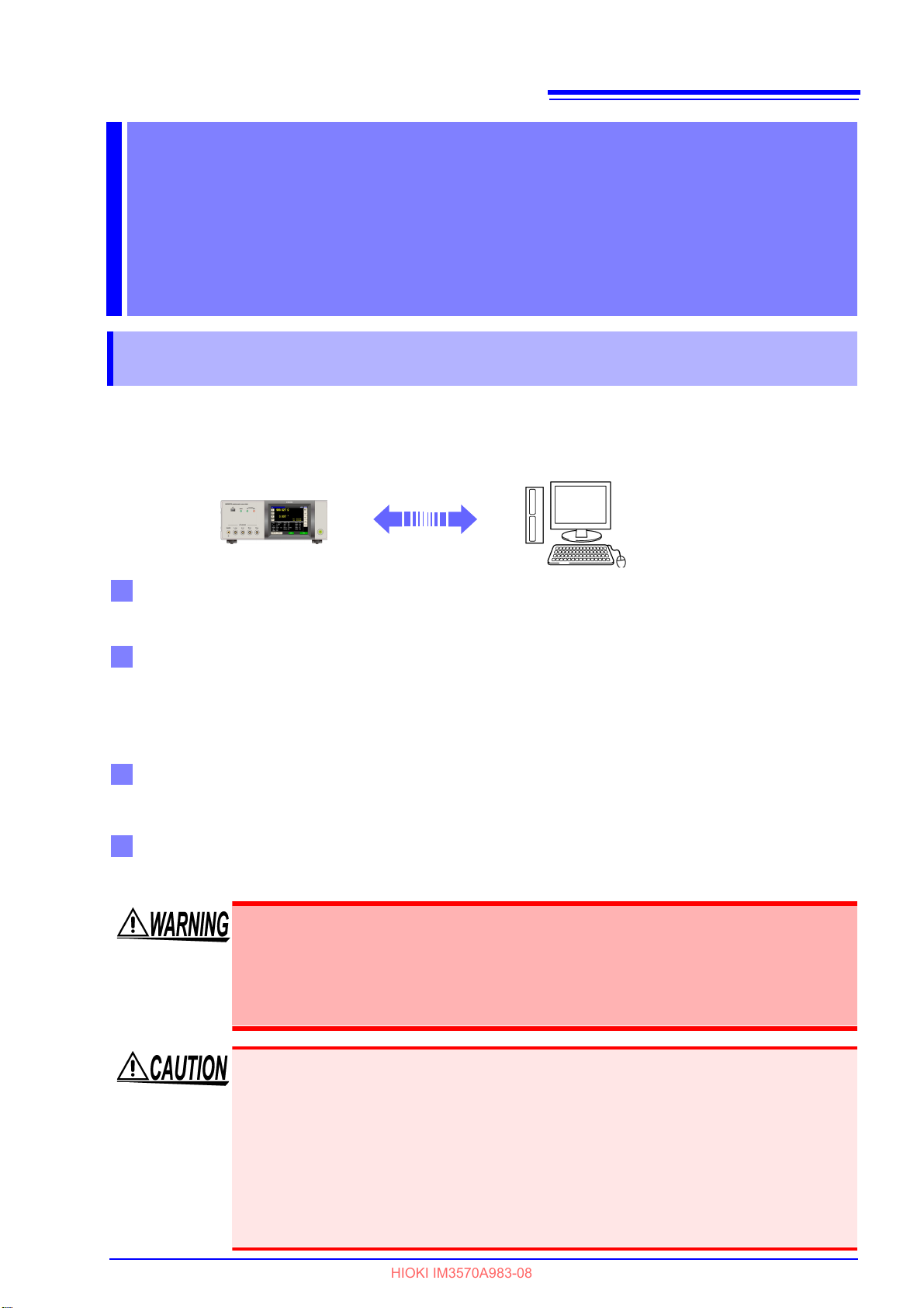
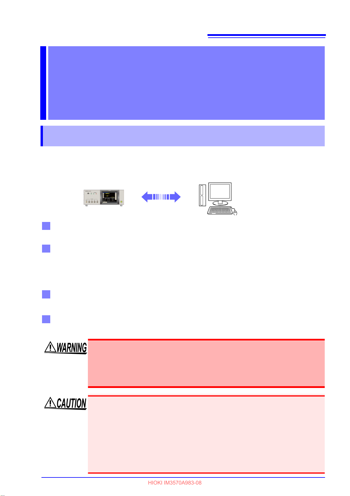
2.1 Overview of Communication
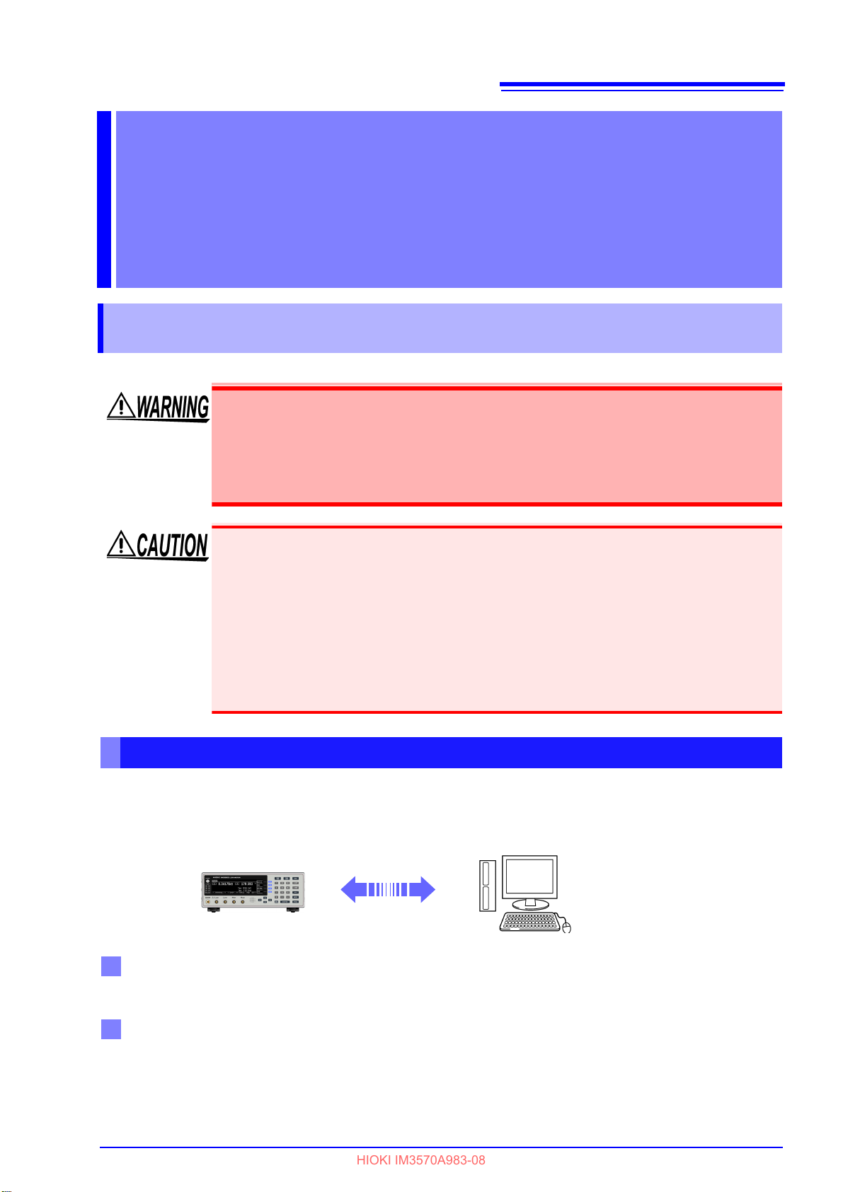
You can control the instrument with communication commands from a computer via the GP-IB, RS-232C,
USB, and LAN interfaces.
There are the following four communication methods. To enable communication, the communication conditions need to be set on the instrument.
Printer can be connected to enable printing measurement values and screens.
0
• Commands common to IEEE-488-2 1987 (requirement) can be used.
• The instrument complies with the following standard. (Compliance standard: IEEE-488.1 1987)
• The instrument has been designed with reference to the following standard. (Reference standard:
IEEE-488.2 1987)
The instrument is communication class compatible.
Command control using the TCP/IP protocol is possible.
• Always turn both devices OFF when connecting and disconnecting an interface
connector. Otherwise, an electric shock accident may occur.
• To avoid damage to the instrument, do not short-circuit the terminal and do not
input voltage to the terminal.
• Failure to fasten the connectors properly may result is sub-specification performance or damage to the equipment.
• To avoid damage, do not disconnect the communications cable while the instrument is
sending or receiving data.
• Use a common ground for both the instrument and the computer. Grounding them to different ground points will result in a potential difference between the instrument's ground
and the computer's ground. If the communications cable is connected while such a potential difference exists, it may result in equipment malfunction or failure.
• Before connecting or disconnecting any communications cable, always turn off the instrument and the computer. Failure to do so could result in equipment malfunction or damage.
• After connecting the communications cable, tighten the screws on the connector securely.
Failure to secure the connector could result in equipment malfunction or damage.
6
When RS-232C is set
When GP-IB is set
When USB is set
When LAN is set
When printer is set
(only IM3570)
HIOKI IM3570A983-08
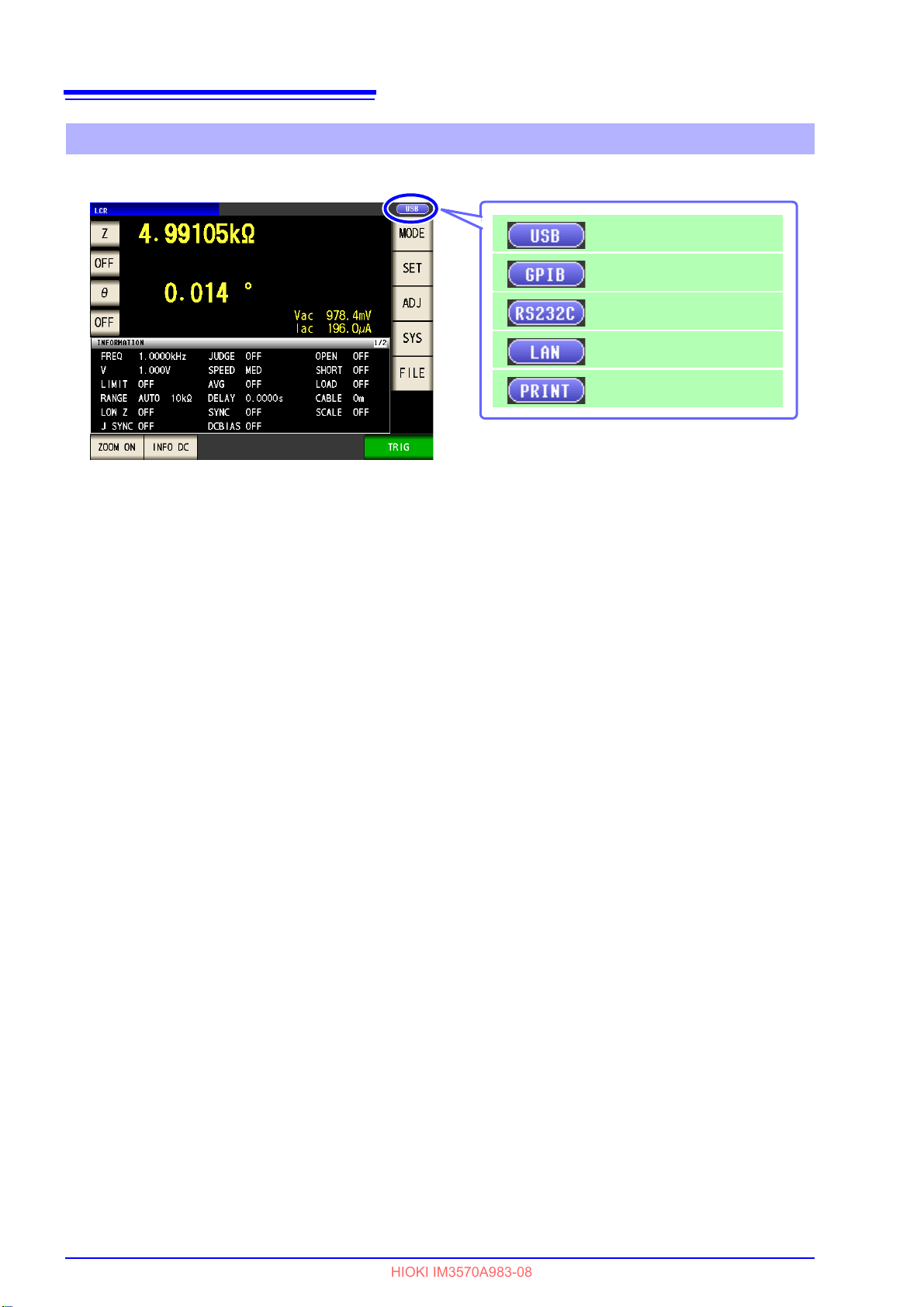
2.1 Overview of Communication
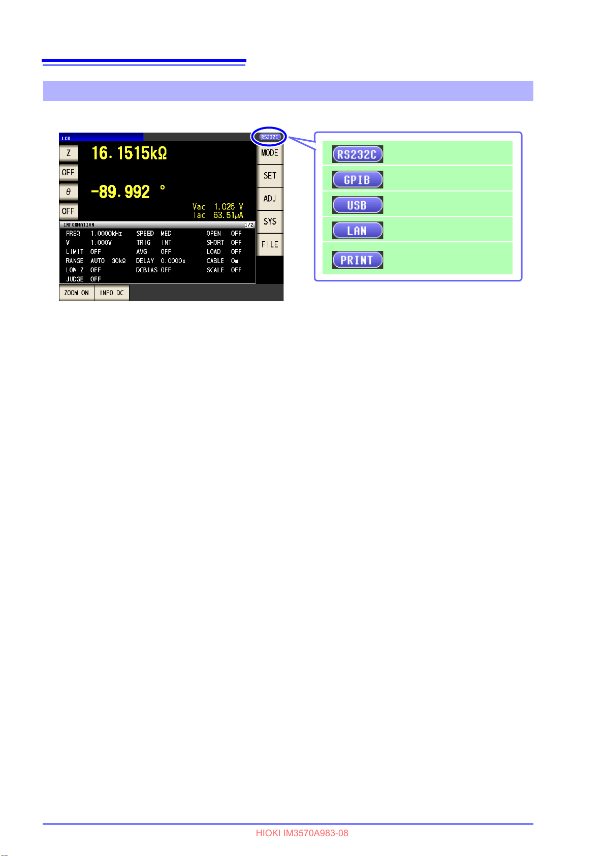
Screen Displayed while Setting Interfaces
When you set an interface, the icon for the set interface is displayed on the right side of the screen.

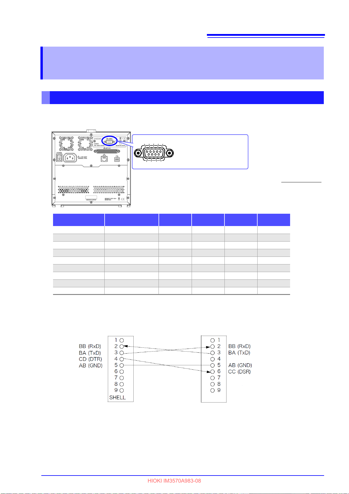
2.2 RS-232C Connection and Settings
Male 9-pin D-sub
#4-40 attaching screws
To connect the instrument to a controller (DTE), use a crossover cable
compatible with the connectors on both the instrument and the controller.
The I/O connector is a DTE (Data Terminal Equipment) configuration.
6 7 8 9
1 2 3 4 5
HIOKI IM3570A983-08
2.2 RS-232C Connection and Settings
Connecting the RS-232C Cable
Connect the RS-232C cable to the RS-232C connector.
(Recommended cable: 9637 RS-232C cable)
7
Connector (D-sub)
Pin No.
1Unused
2 Received Data 104 BB RD RxD
3 Transmitted Data 103 BA SD TxD
4 Unused 108/2 CD ER DTR
5 Signal Ground 102 AB SG GND
6 Unused
7 Request to Send 105 CA RS RTS
8 Clear to Send 106 CB CS CTS
9Unused
Interchange Circuit
Name
CCITT
Circuit No.
EIA
Abbreviation
Example: Connecting to a DOS/V PC
Specification: D-sub 9-pin female and female connector, reverse connection
JIS
Abbreviation
Common
Abbreviation
Hardware control will not work properly if you use a cable that has CA(RTS) and CB(CTS)
short-circuited.
8
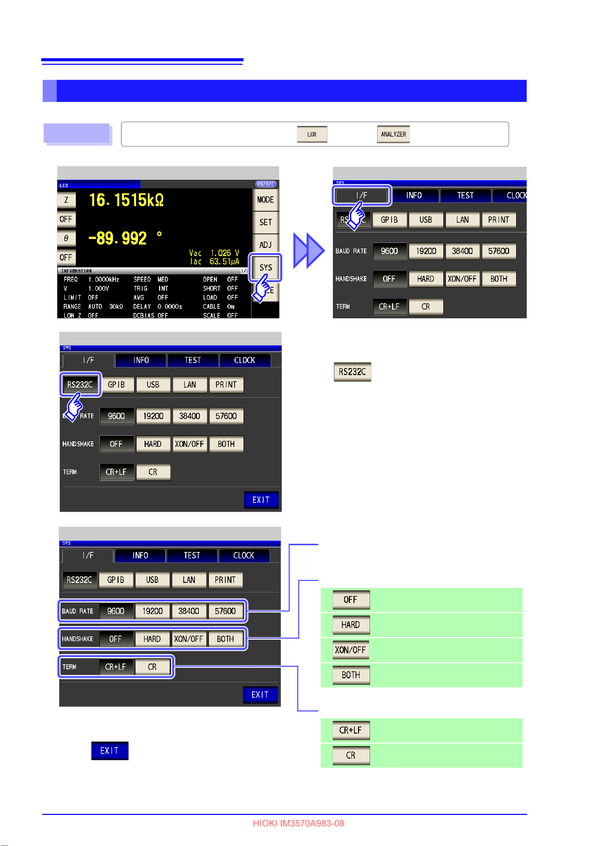
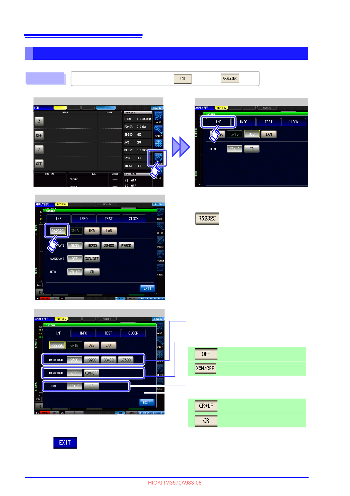
Procedure
LCR Measurement Screen
Interface Settings
You can configure the setting from any of mode and mode (only IM3570).
Press .
RS-232C Settings
Press to confirm the setting.
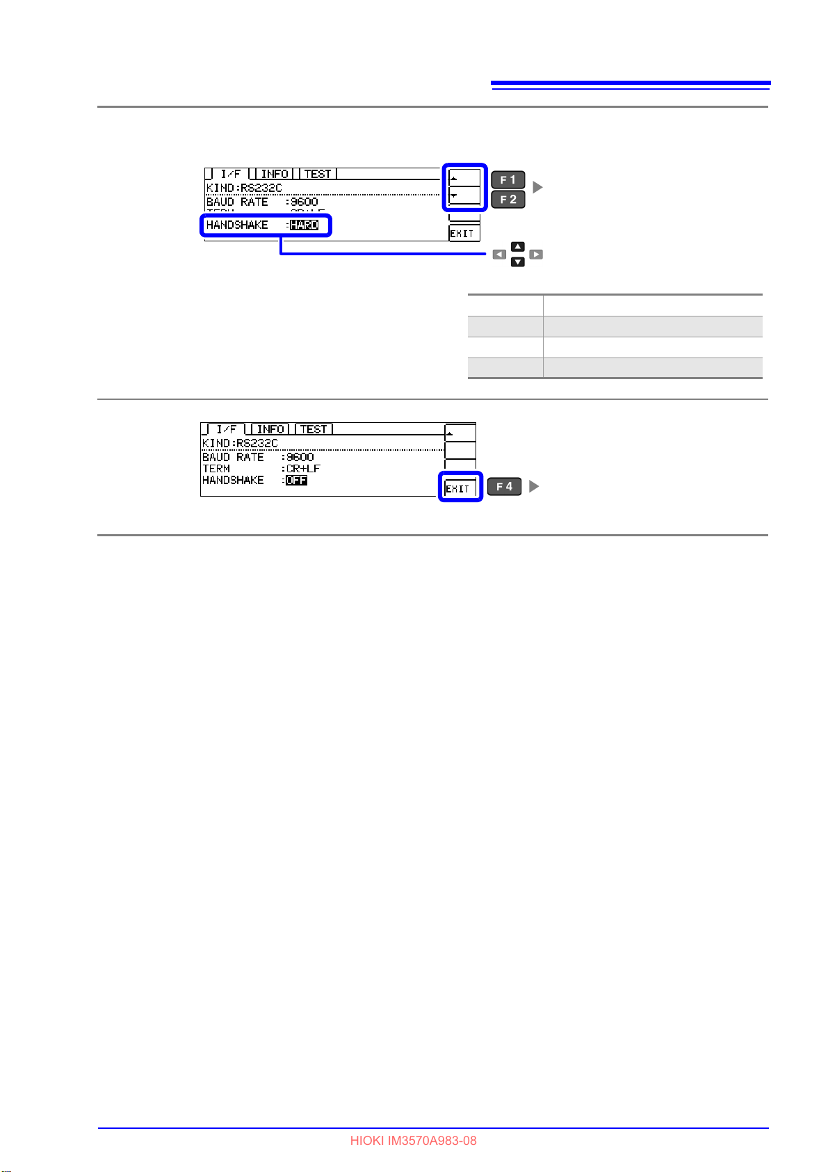
RS-232C Settings
Select the terminator setting.
CR+LF
CR
Select the baud rate setting.
Select the handshake setting.
No flow control
Hardware (RTS/CTS control)
Software (XON/XOFF control)
Hardware + software
HIOKI IM3570A983-08
2.2 RS-232C Connection and Settings
Setting RS-232C

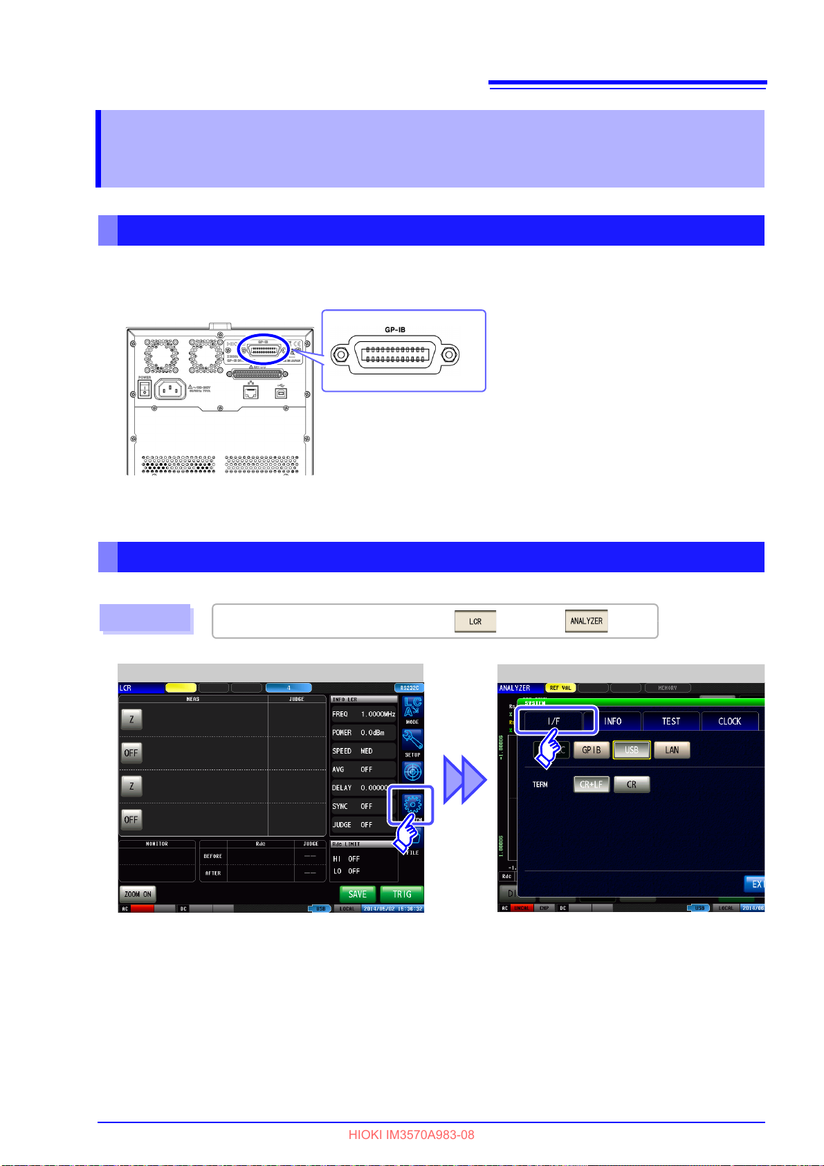
2.3 GP-IB Connection and Settings
Recommended cable:
9151-02 GP-IB connection cable (2 m)
Procedure
LCR Measurement Screen
Interface Settings
You can configure the setting from any of mode and mode (only IM3570).
HIOKI IM3570A983-08
2.3 GP-IB Connection and Settings
Connecting the GP-IB Cable
Connect the GP-IB cable to the GP-IB connector.
9
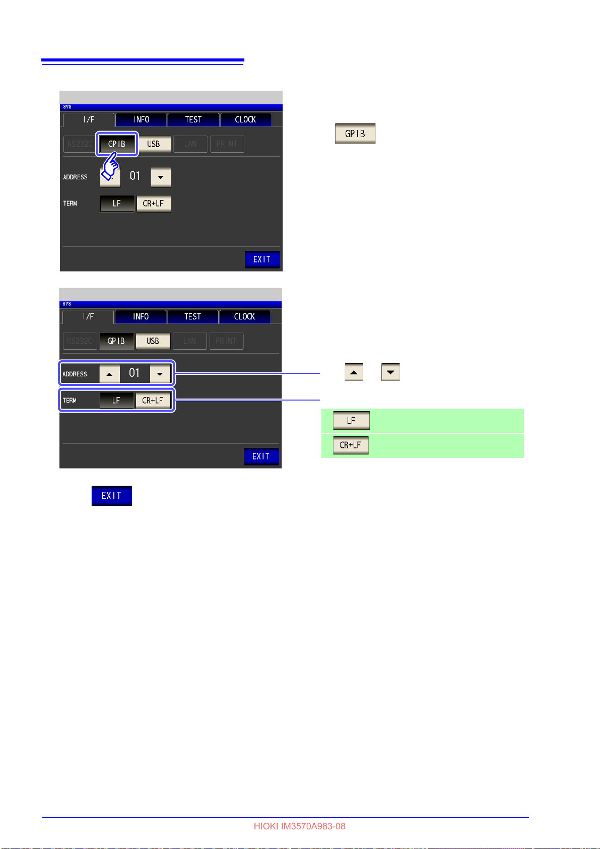
Setting GP-IB

10
Press .
GPIB Setting
GPIB Setting
Use or to set the GP-IB address.
Select the terminator setting.
LF with EOI
LF with CR+EOI
Press to confirm the setting.
HIOKI IM3570A983-08
2.3 GP-IB Connection and Settings

2.4 USB Settings and Connection
To connect the instrument to a computer the first time, a dedicated USB driver must be installed.
Before connecting the instrument to the computer, install the USB driver.
The USB driver can be downloaded from the bundled CD, or our web site.(http://www.hioki.com)
The USB driver is compatible with the Windows 7 (32-bit, 64-bit version), Windows 8 (32-bit, 64-bit
version), Windows 10 (32-bit, 64-bit version), and Windows 11 (64-bit version) operating systems.
Additionally, do not put the computer into the sleep state while the instrument is connected to the
computer.
Procedure
LCR Measurement Screen
Interface Settings
You can configure the setting from any of mode and mode (only IM3570).
Press .
USB Setting
HIOKI IM3570A983-08
2.4 USB Settings and Connection
Setting USB
11
12
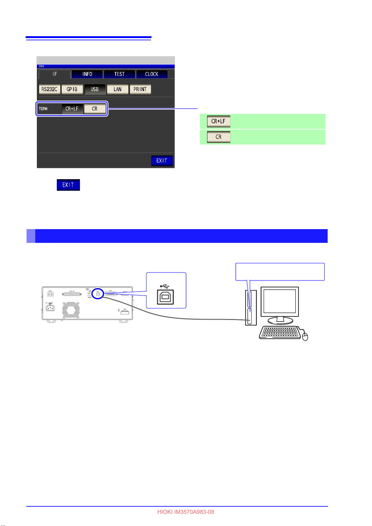
USB Setting
Select the terminator setting.
CR+LF
CR
Press to confirm the setting.
USB cable
(commercially available product)
USB interface port of computer
Type B
HIOKI IM3570A983-08
2.4 USB Settings and Connection
Connecting the USB Cable
Connect a USB cable (commercially available USB cable) to the USB port of the instrument.
2.5 LAN Settings and Connection
• Make these settings before connecting to a network. Changing settings while connected can
duplicate IP addresses of other network devices, and incorrect address information may otherwise be presented to the network.
• The instrument does not support DHCP (automatic IP address assignment) on a network.
Setting Items
Network Environment Configuration
IP Address _________._________._________._________
Subnet Mask _________._________._________._________
Default Gateway _________._________._________._________
HIOKI IM3570A983-08
2.5 LAN Settings and Connection
LAN Settings
You can perform command control using the TCP/IP protocol.
Set the instrument to match your network environment in advance.
Identifies each device connected on a network.
IP address
Subnet mask
Default Gateway
Each network device must be set to a unique address.
The instrument supports IP version 4, with IP addresses indicated as four decimal octets, e.g.,
“192.168.0.1”.
This setting is for separating the IP address into the network address that indicates the network and
the host address that indicates the instrument. On this instrument, the subnet mask is represented as
four decimal numbers separated by “. ” such as “255.255.255.0.”
When the computer and instrument are on different but overlapping networks (subnets), this IP address specifies the device to serve as the gateway between the networks.
If the computer and instrument are connected one-to-one, no gateway is used, and the instrument's
default setting “0.0.0.0” can be kept as is.
13
Example 1. Connecting the instrument to an existing network
When connecting the instrument to an existing network, the network settings need to be confirmed in
advance.
An IP address which is not the same as that of another network device needs to be assigned.
Confirm the following items with the network administrator, and write them down.
Example 2. Connecting multiple instruments to a single computer using a hub
When building a local network with no outside connection, the following private IP addresses are recommended.
Example of private IP address:
IP Address ...............Computer: 192.168.0.100
Instrument: 192.168.0.1, 192.168.0.2, 192.168.0.3...
(Set an IP address that differs from that of other network devices.)
Subnet Mask............255.255.255.0
Default Gateway ...... OFF(0.0.0.0)
Example 3. Connecting one instrument to a single computer using the 9642 LAN Cable
The 9642 LAN Cable can be used with its supplied connection adapter to connect one instrument to one
computer, in which case the IP address is freely settable. Use the recommended private IP addresses.
IP Address ...............Computer: 192.168.0.100
Instrument: 192.168.0.1 (Set to a different IP address than the computer.)
Subnet Mask............255.255.255.0
Default Gateway ...... OFF(0.0.0.0)
14
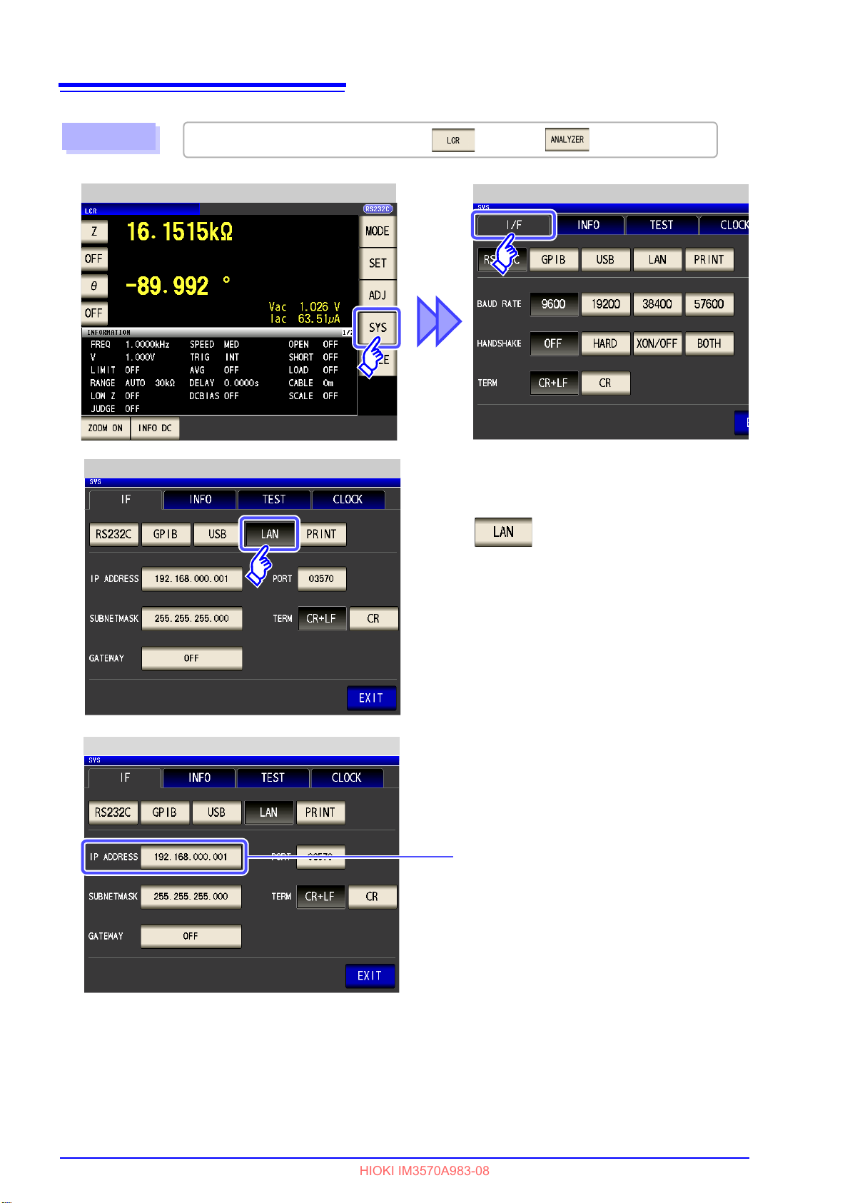
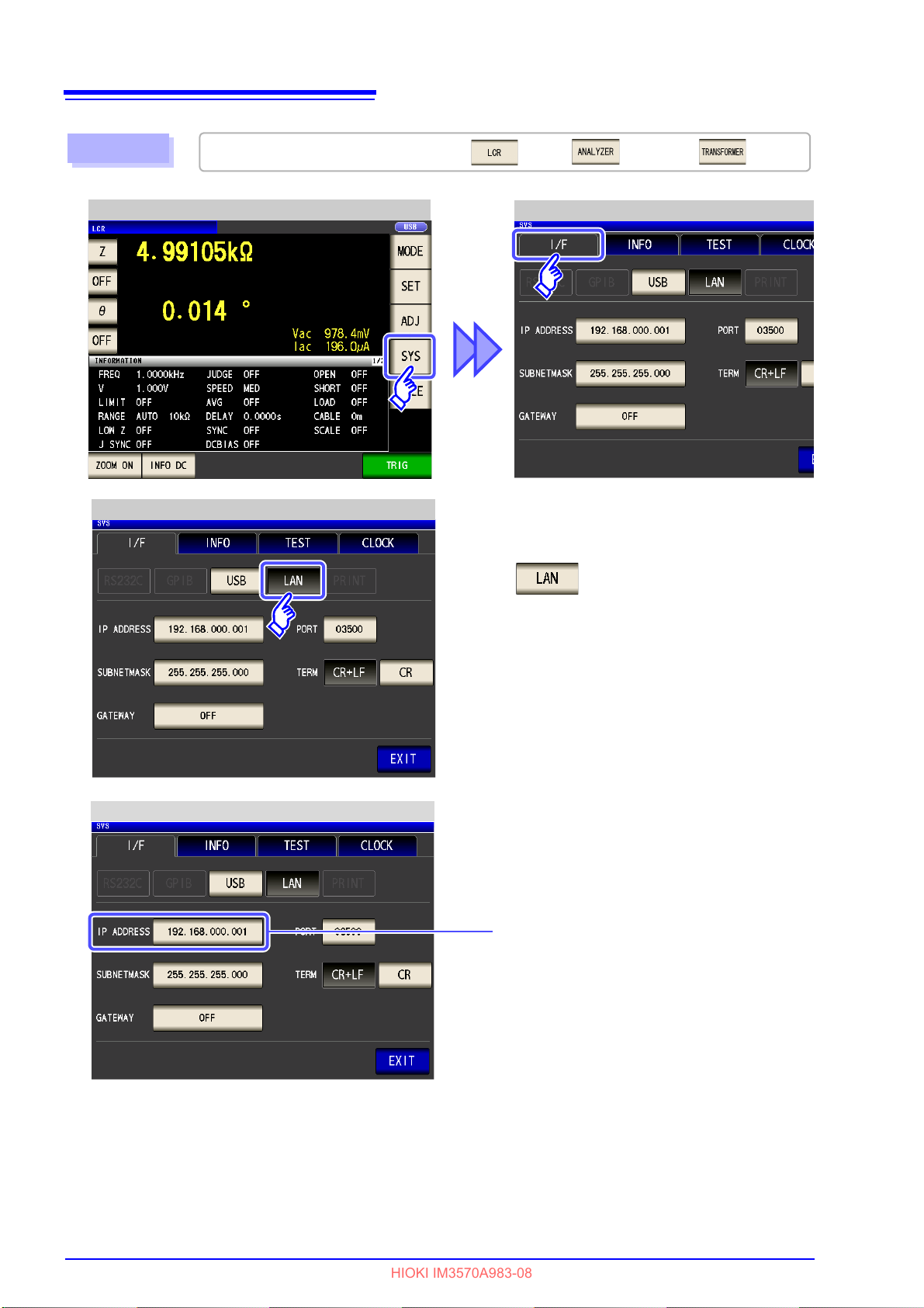
Procedure
LCR Measurement Screen
Interface Settings
You can configure the setting from any of mode and mode (only IM3570).
Press .
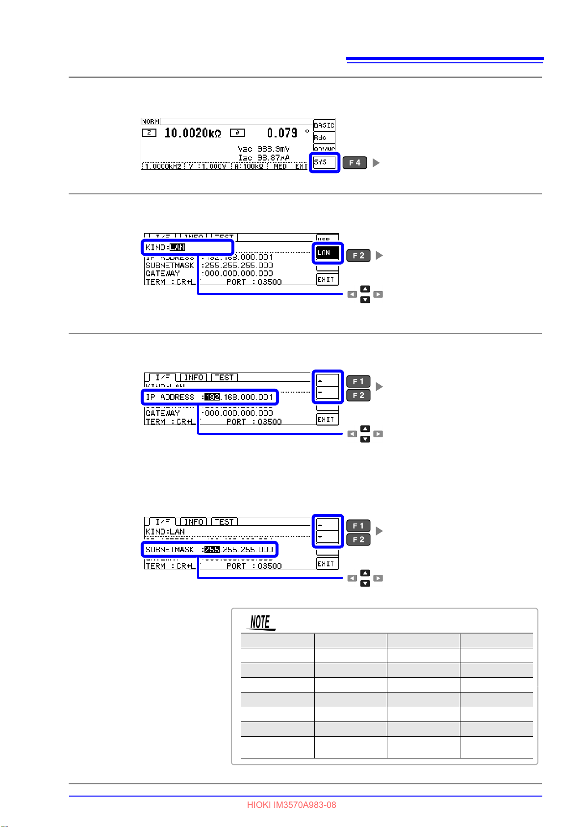
LAN Settings
LAN Settings
Select the IP address.
HIOKI IM3570A983-08
2.5 LAN Settings and Connection
15
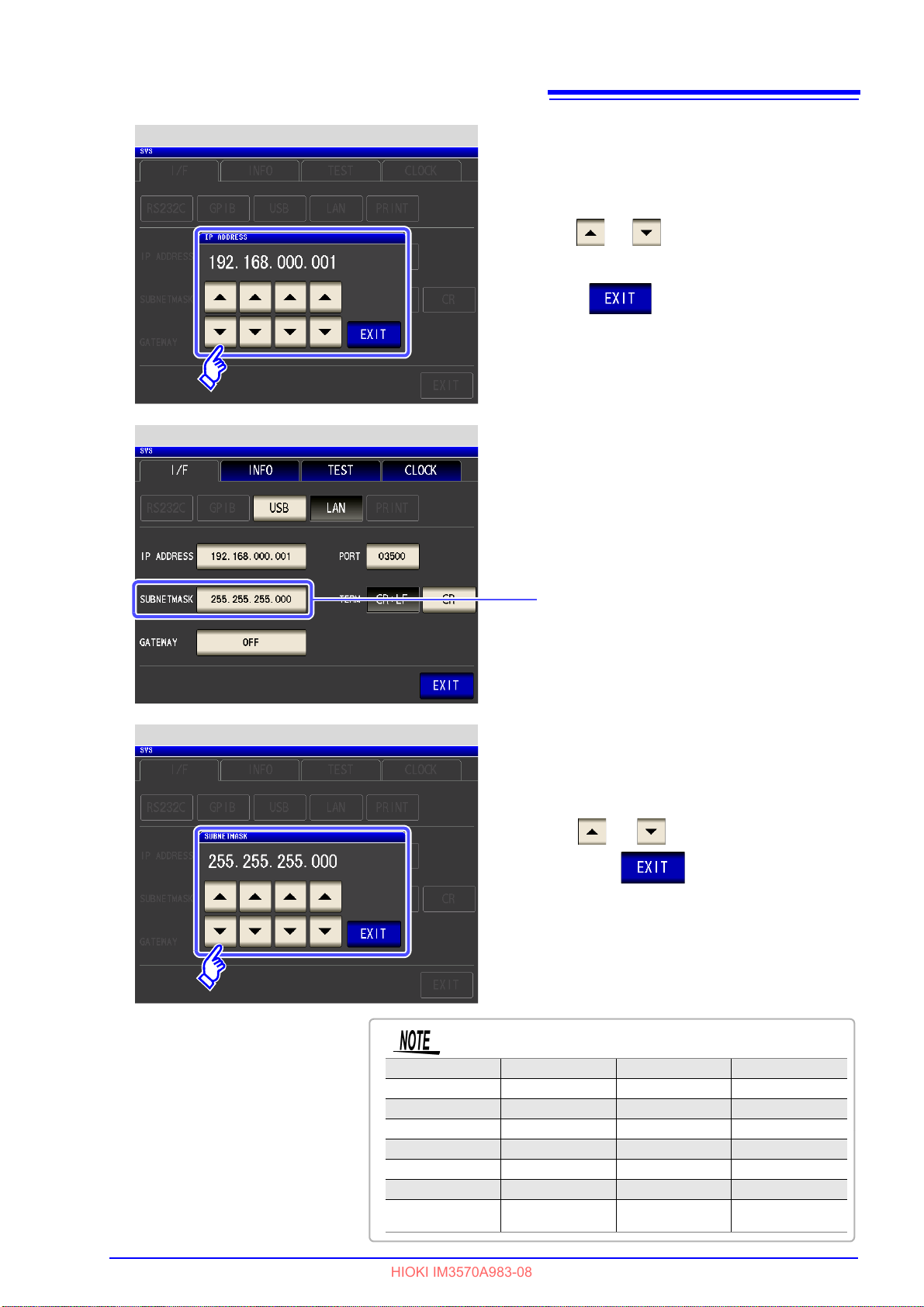
IP address Settings
Use or to set the IP address.
Press to confirm the setting.
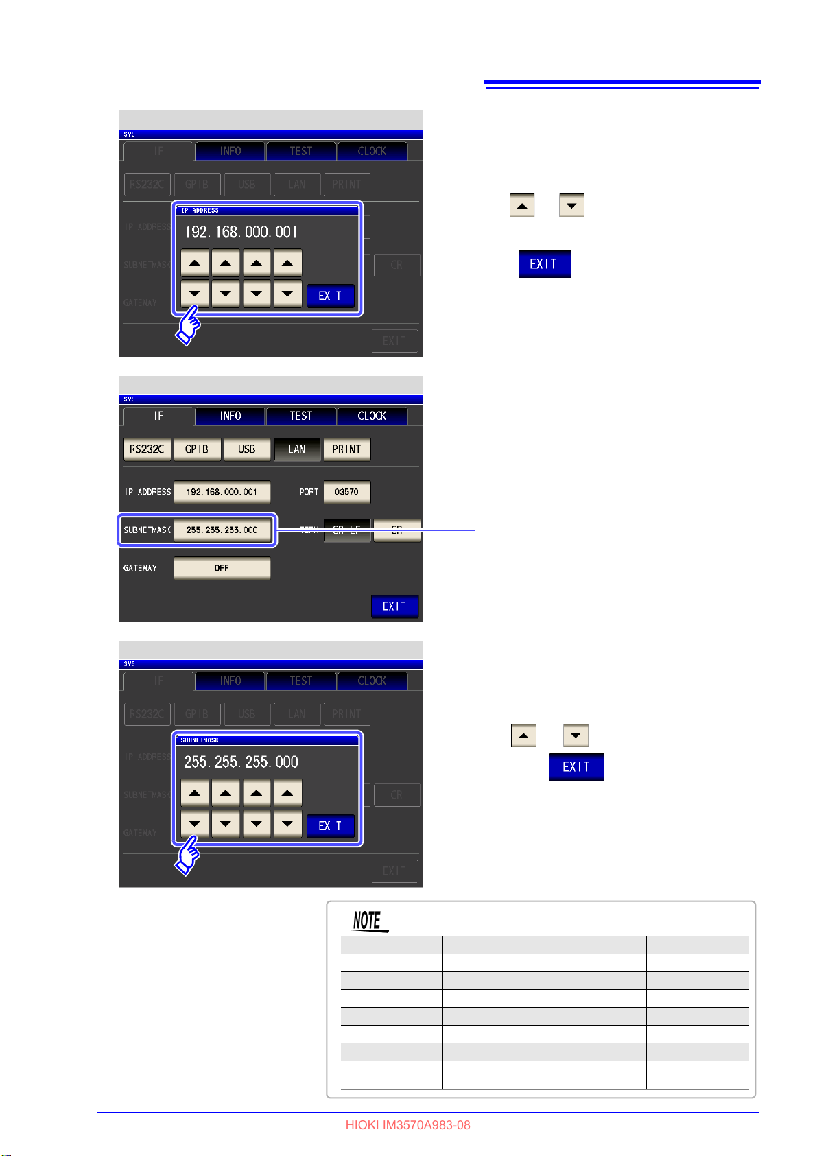
LAN Settings
Select the subnet mask.
128.000.000.000 255.128.000.000 255.255.128.000 255.255.255.128
192.000.000.000 255.192.000.000 255.255.192.000 255.255.255.192
224.000.000.000 255.224.000.000 255.255.224.000 255.255.255.224
240.000.000.000 255.240.000.000 255.255.240.000 255.255.255.240
248.000.000.000 255.248.000.000 255.255.248.000 255.255.255.248
252.000.000.000 255.252.000.000 255.255.252.000 255.255.255.252
254.000.000.000 255.254.000.000 255.255.254.000
255.000.000.000 255.255.000.000 255.255.255.000
(Initial setting)
Subnet mask Settings
Use or to set the subnet mask,
and press to confirm the setting.
Any of the following 30 subnet masks can be set for the instrument.
HIOKI IM3570A983-08
2.5 LAN Settings and Connection

16
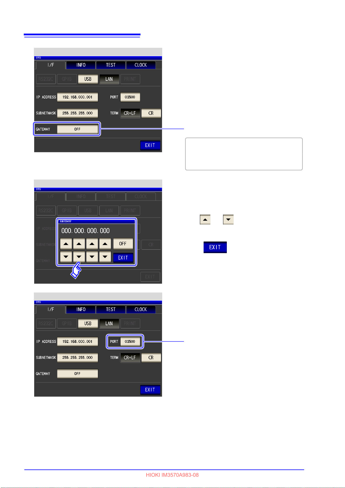
LAN Settings
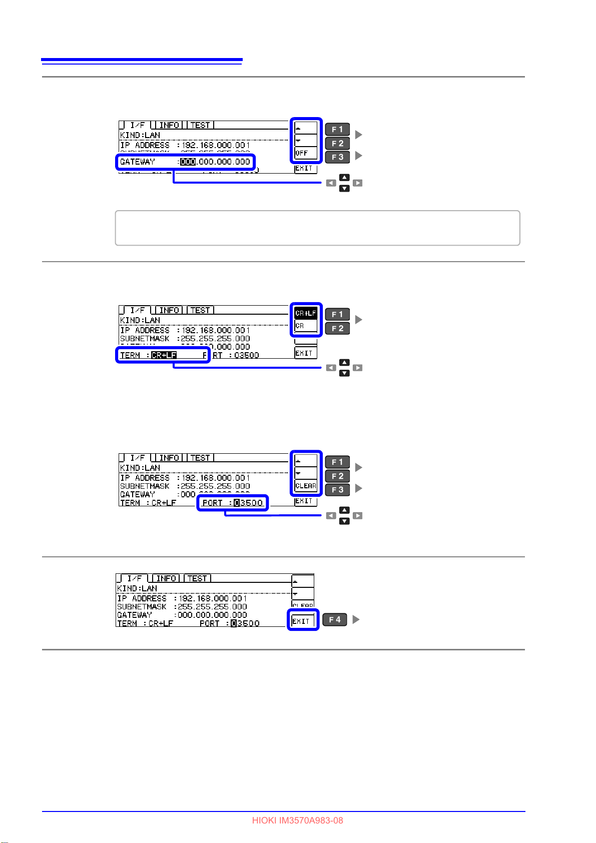
Select the default gateway.
If the default gateway does not need to be set, for
example, when connecting the instrument and
computer on a one-to-one basis using a cross cable, leave this set to OFF.
Default gateway Settings
Use or to set the default gate-
way.
Press to confirm the setting.
LAN Settings
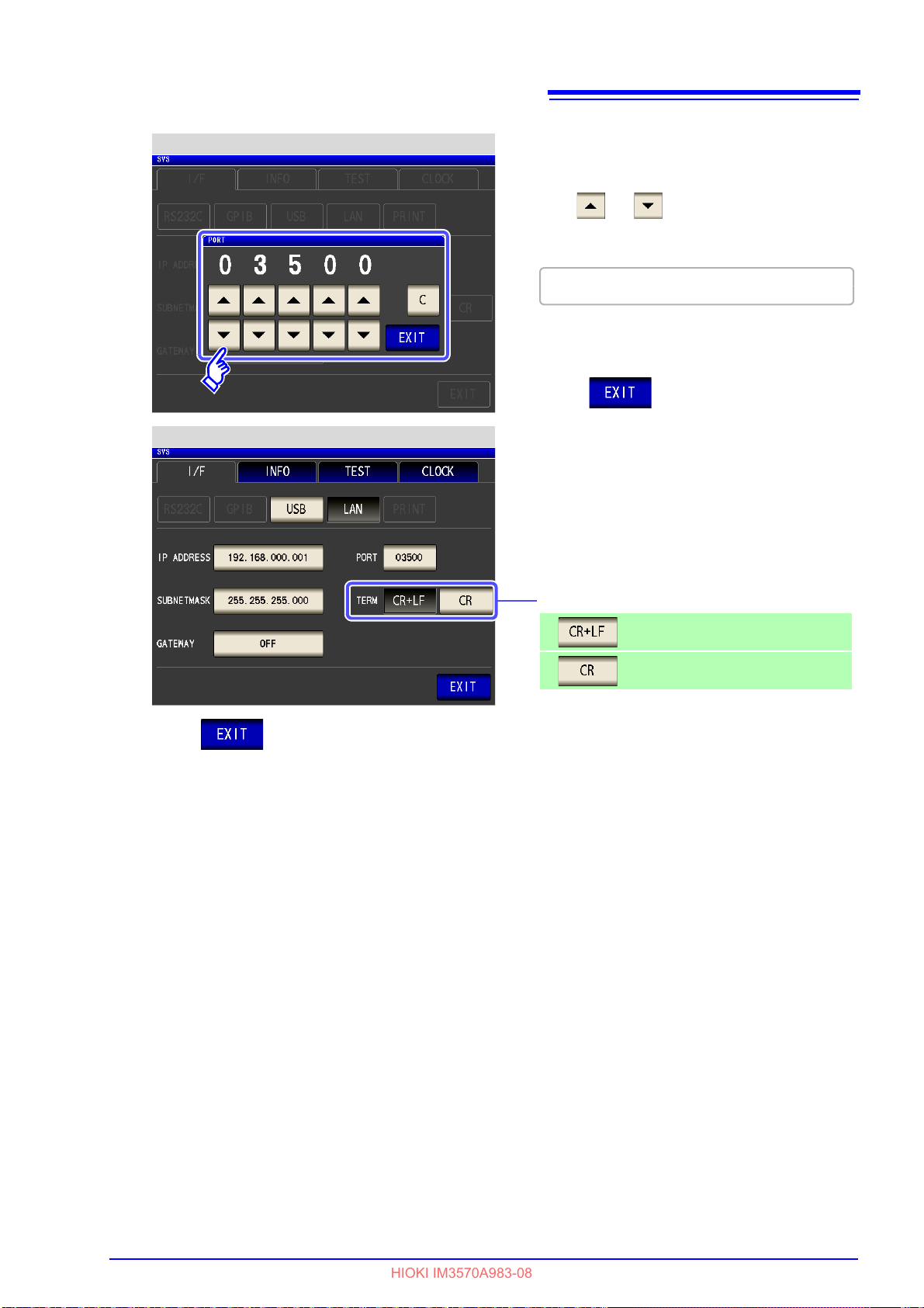
Select the port number.
HIOKI IM3570A983-08
2.5 LAN Settings and Connection

17
Port number Settings
Use or to set the port number to
use for communication commands.
Press to confirm the setting.
Settable range : 1024 to 65535
LAN Settings
Select the terminator setting.
CR+LF
CR
Press to confirm the setting.
HIOKI IM3570A983-08
2.5 LAN Settings and Connection

18
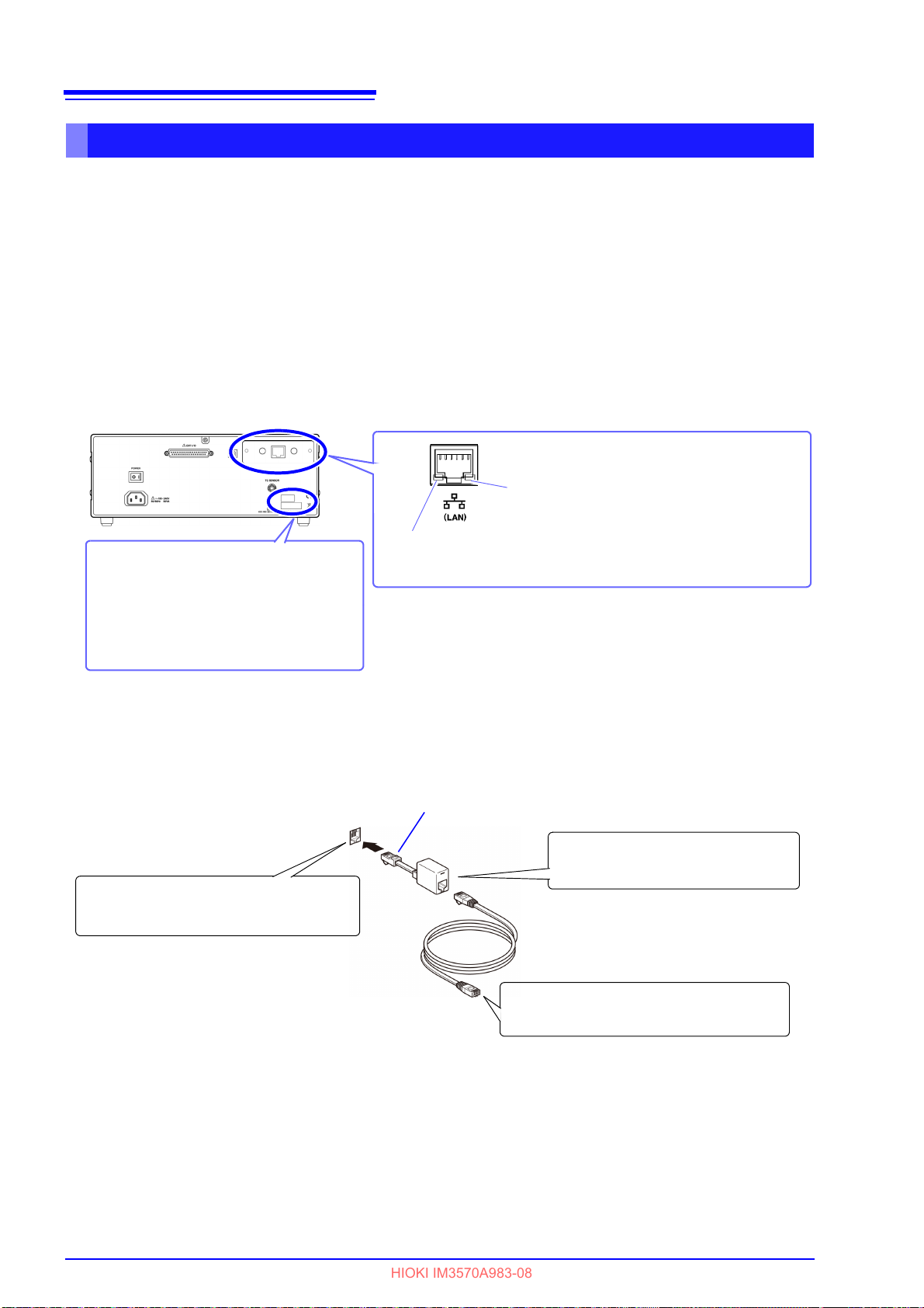
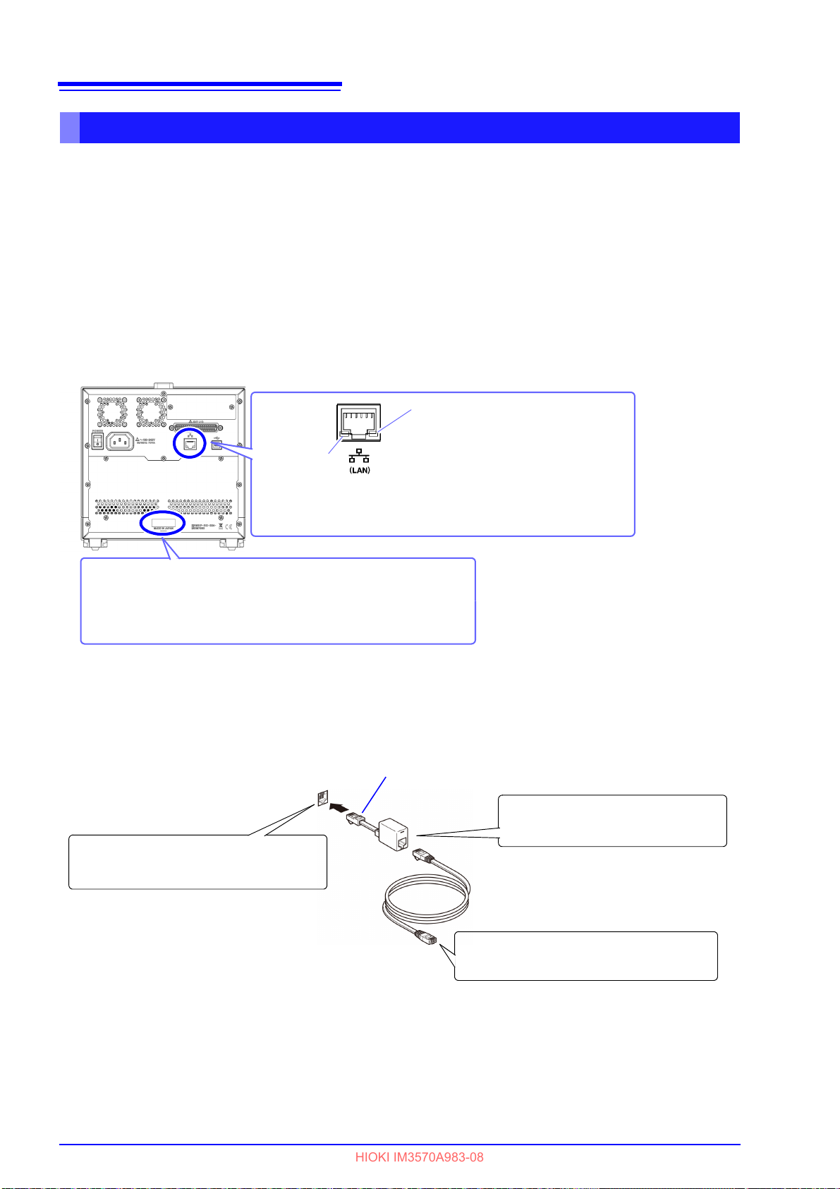
On: Performing communication with 100BASE.
Off: Performing communication with 10BASE.
Flashes when data is being exchanged.
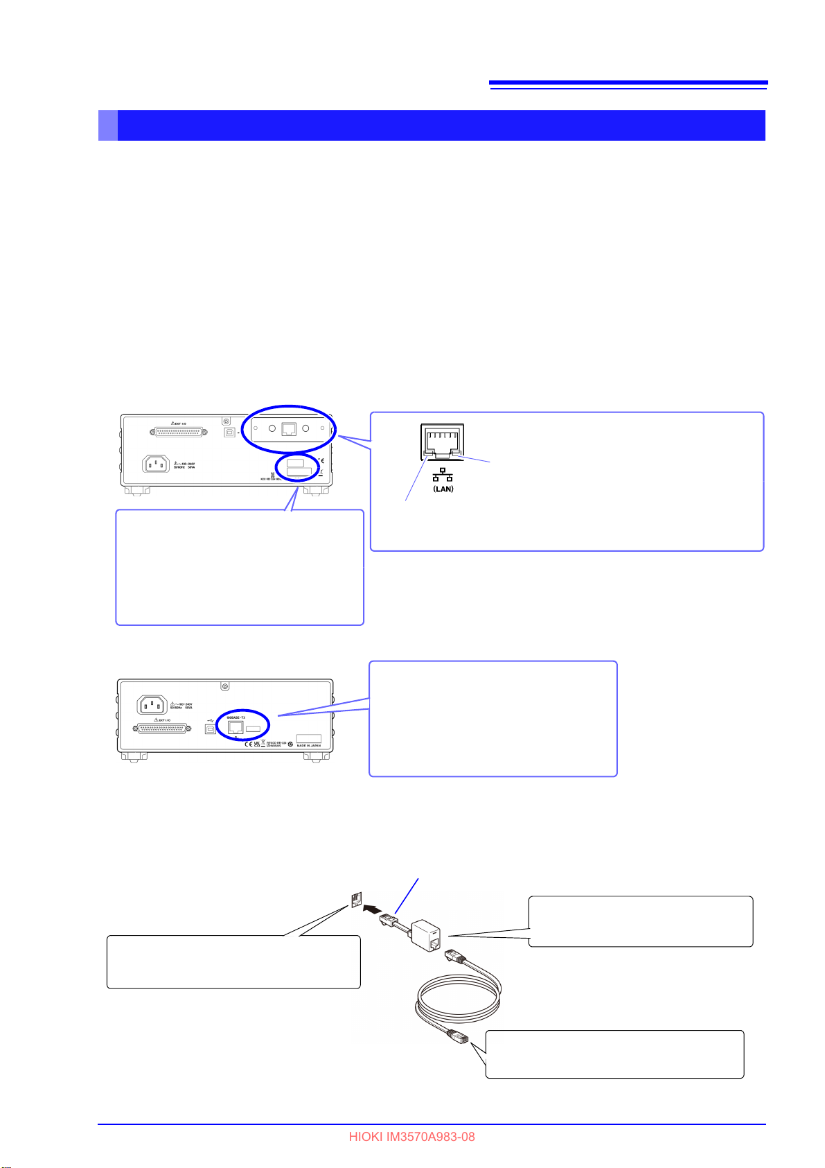
SPEED LED
RX/TX LED
The MAC address of the LAN is displayed
below the serial number.
You can also check it on the instrument
screen.
See: “Checking the Version of the Instru-
ment” in the instruction manual.
LAN interface
Crossover adapter
Connecting with the 9642 LAN Cable and crossover adapter (supplied with the 9642)
1
Connect the LAN Cable to the
crossover adapter.
Connect the crossover adapter to
the LAN interface on the instrument.
2
Connect the LAN Cable to the
100BASE-TX connector on the PC.
3
HIOKI IM3570A983-08
2.5 LAN Settings and Connection
Connecting a LAN Cable
Use a LAN cable to connect the instrument and computer.
When connecting the instrument to your LAN using a LAN cable of more than 30 m or
with the cable laid outdoors, take appropriate countermeasures that include installing a surge protector for LANs. Such signal wiring is susceptible to induced lighting,
which can cause damage to the instrument.
Required items:
When connecting the instrument to an existing network (prepare any of the following):
• Straight-through Cat 5, 100BASE-TX-compliant Ethernet cable (up to 100 m, commercially available).
For 10BASE communication, a 10BASE-T-compliant cable may also be used.
• Hioki 9642 LAN Cable (option)
(A cross adapter cannot be used.)
When connecting one instrument to a single computer (prepare one of the following):
• 100BASE-TX-compliant cross-over cable (up to 100 m)
• 100BASE-TX-compliant straight-through cable with cross-over adapter (up to 100 m)
• Hioki 9642 LAN Cable (option)
When connecting the instrument to a single computer (connect the instrument to the computer)
19
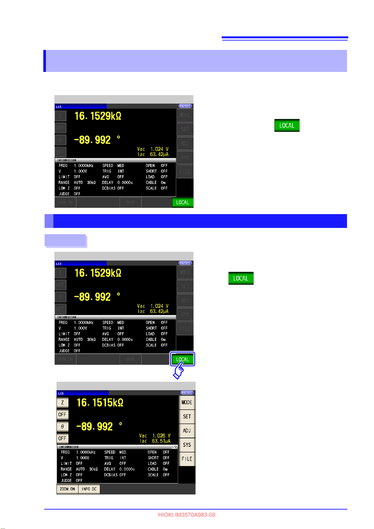
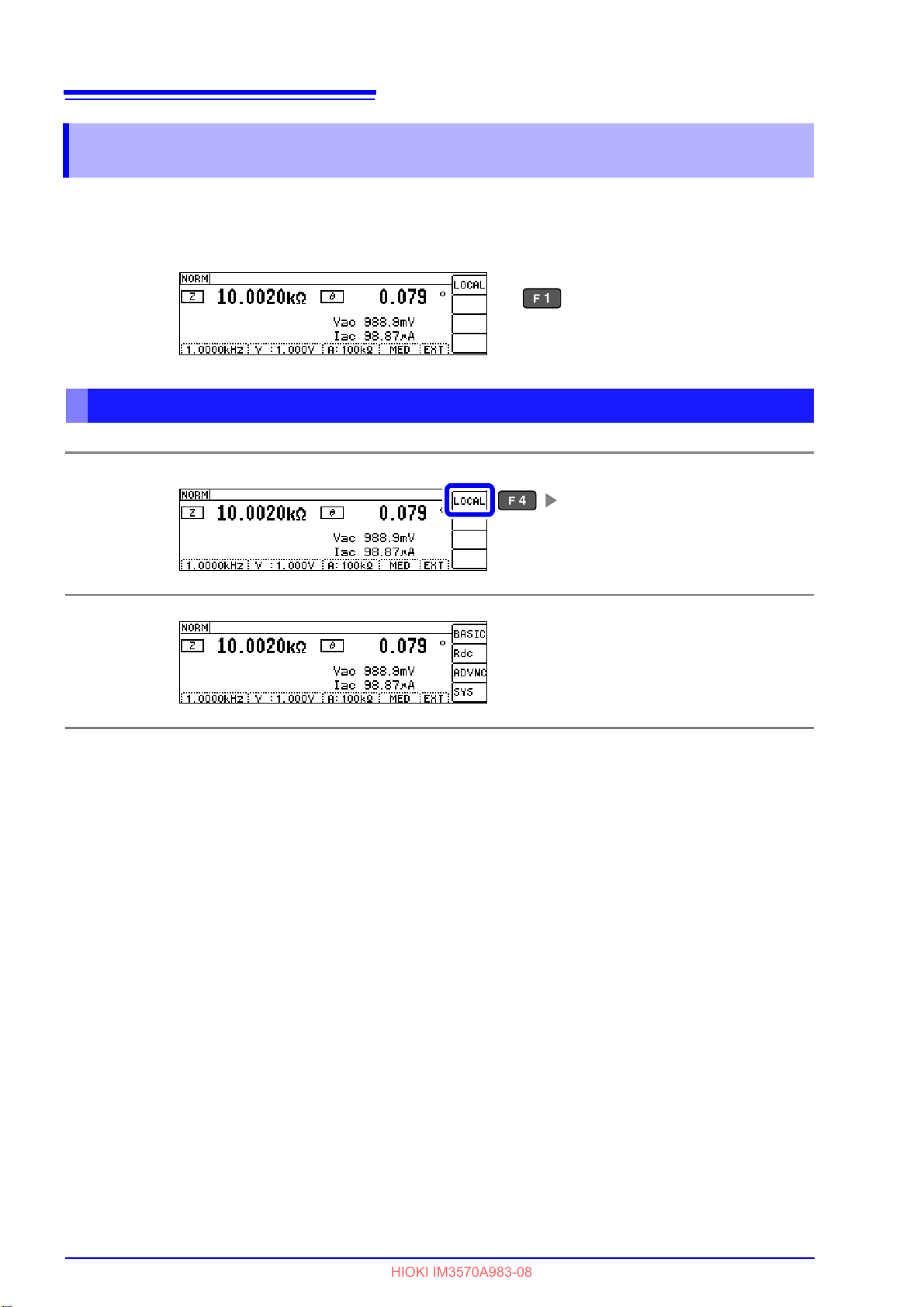
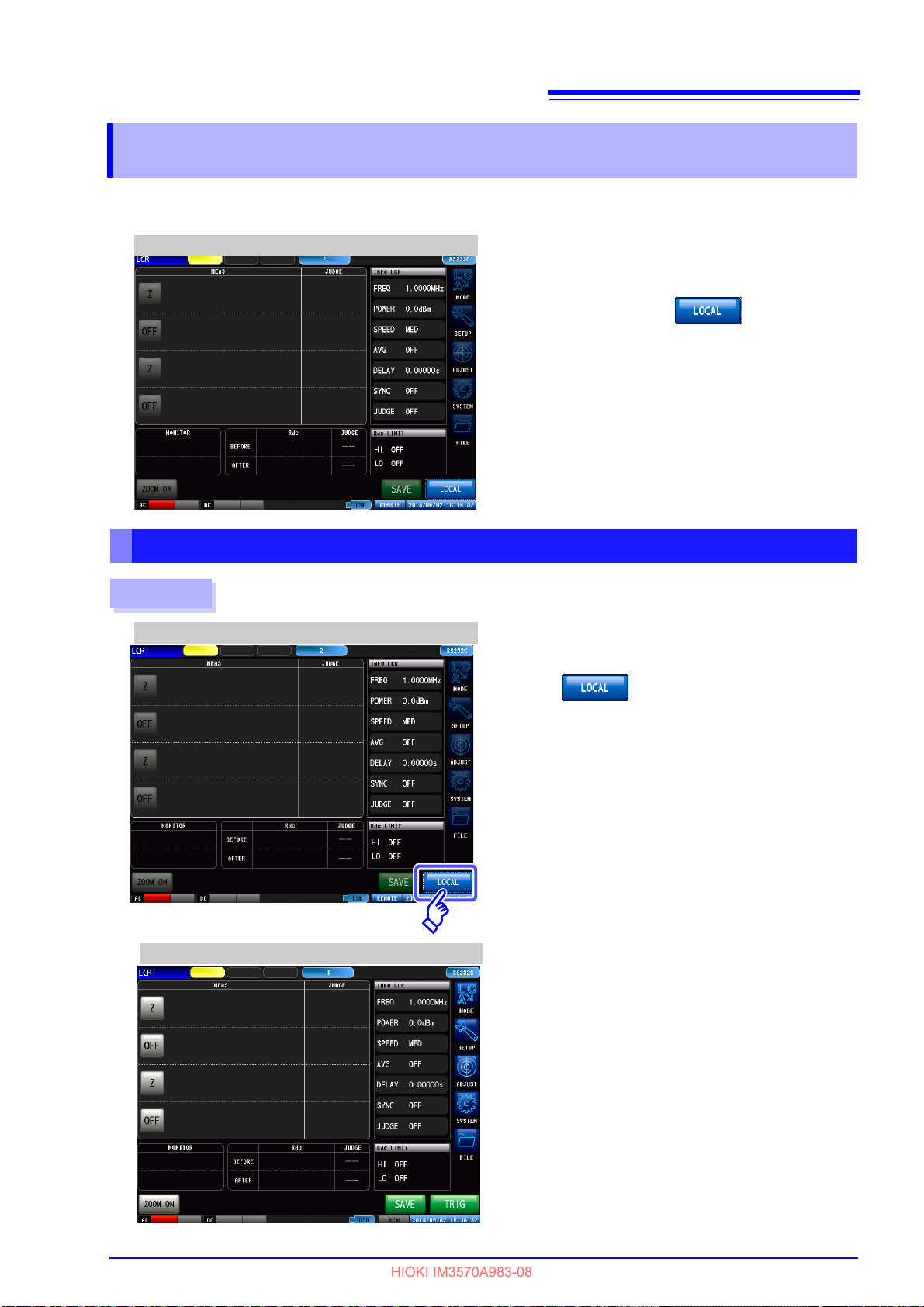
All of the keys except are disabled.
Remote Mode State
Procedure
Press to return to the normal state
(local state).
1
The measurement screen is redisplayed.
Local State
LCR Measurement Screen
HIOKI IM3570A983-08
2.6 Remote Mode
2.6 Remote Mode
When you connect a device to an interface and start communication, the mode becomes remote mode
(remote operation state) and the keys on the LCD are disabled.
Canceling Remote Mode

20
HIOKI IM3570A983-08
2.6 Remote Mode
3.1 Overview of Communication
USB communication (p. 23)
GP-IB communication (when connected to the Z3000) (p. 25)
HIOKI IM3570A983-08
Model IM3523/ IM3523A
Connection and
Setting Chapter 3
3.1 Overview of Communication
• Always turn both devices OFF when connecting and disconnecting an interface
connector. Otherwise, an electric shock accident may occur.
• To avoid damage to the instrument, do not short-circuit the terminal and do not
input voltage to the terminal.
• Failure to fasten the connectors properly may result is sub-specification performance or damage to the equipment.
21
• To avoid damage, do not disconnect the communications cable while the instrument is
sending or receiving data.
• Use a common ground for both the instrument and the computer. Grounding them to different ground points will result in a potential difference between the instrument's ground
and the computer's ground. If the communications cable is connected while such a potential difference exists, it may result in equipment malfunction or failure.
• Before connecting or disconnecting any communications cable, always turn off the instrument and the computer. Failure to do so could result in equipment malfunction or damage.
• After connecting the communications cable, tighten the screws on the connector securely.
Failure to secure the connector could result in equipment malfunction or damage.
IM3523
You can control the instrument with communication commands from a computer via the USB, GP-IB, RS232C and LAN interfaces.
There are the following four communication methods. To enable communication, the communication conditions need to be set on the instrument.
The instrument is communication class compatible.
• Commands common to IEEE-488-2 1987 (requirement) can be used.
• The instrument complies with the following standard. (Compliance standard: IEEE-488.1 1987)
• The instrument has been designed with reference to the following standard. (Reference standard:
IEEE-488.2 1987)

22
RS-232C communication (when connected to the Z3001) (p. 27)
LAN communication (when connected to the Z3002) (p. 30)
USB communication (p. 23)
LAN communication (p. 30)
HIOKI IM3570A983-08
3.1 Overview of Communication
Printer can be connected to enable printing measurement values and screens.
Command control using the TCP/IP protocol is possible.
IM3523A
You can control the instrument with communication commands from a computer via the USB and LAN interfaces.
There are the following two communication methods. To enable communication, the communication conditions need to be set on the instrument.
The instrument is communication class compatible.
Command control using the TCP/IP protocol is possible.

3.2 USB Settings and Connection
IM3523
To connect the instrument to a computer the first time, a dedicated USB driver must be installed.
Before connecting the instrument to the computer, install the USB driver.
The USB driver can be downloaded from the bundled CD, or our web site. (http://www.hioki.com)
IM3523A
When the instrument is connected to a computer, the USB driver is automatically installed. Since
the OS standard driver is installed, it is not necessary to install another driver.
The USB driver is compatible with the Windows 7 (32-bit, 64-bit version), Windows 8 (32-bit, 64-bit
version), Windows 10 (32-bit, 64-bit version), and Windows 11 (64-bit version) operating systems.
Additionally, do not put the computer into the sleep state while the instrument is connected to the
computer.
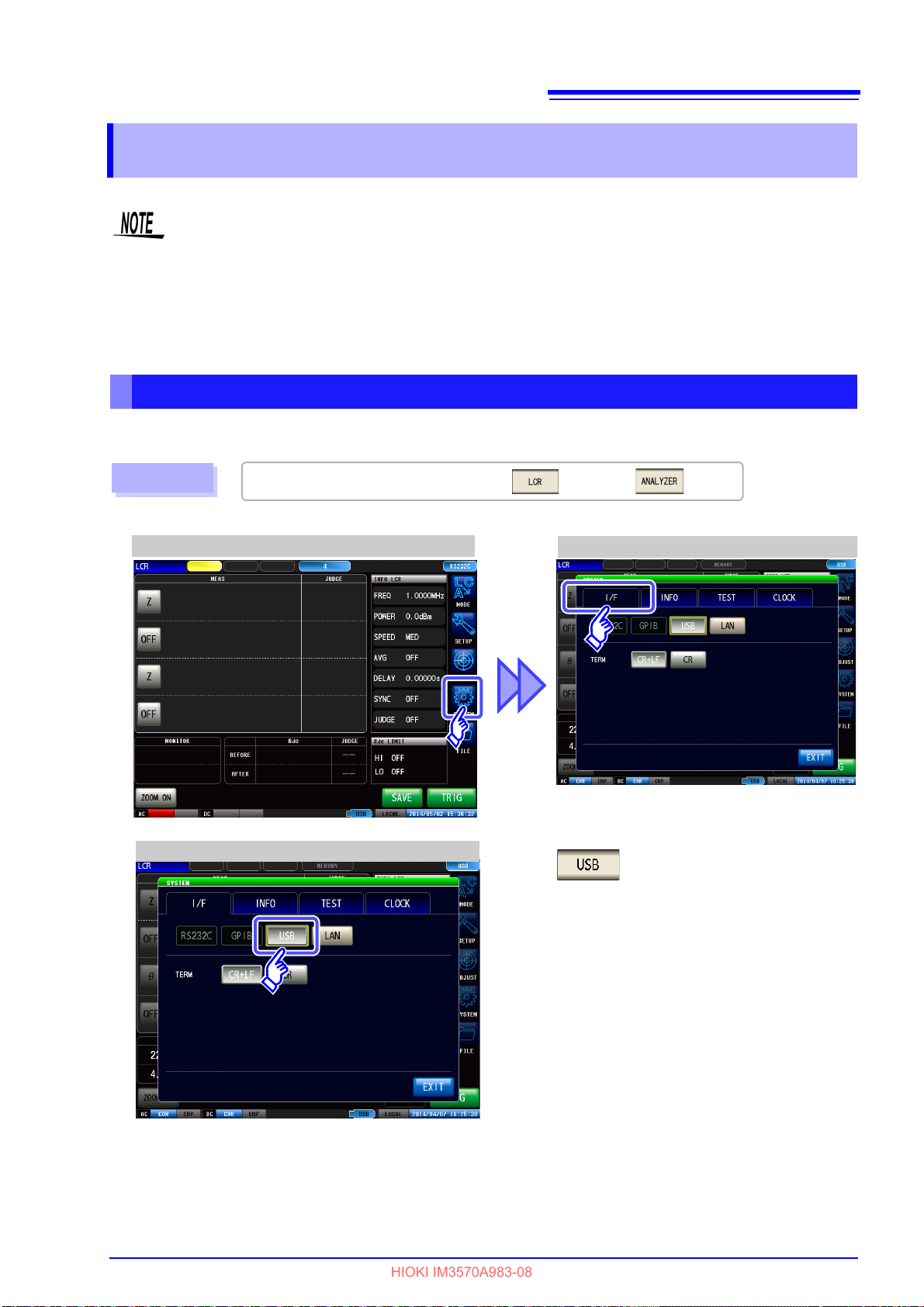
The SYSTEM screen will be displayed.
Select.
1
Select USB.
2
Selected interface
Using the Z3000
Using the Z3001
Using the Z3002
When an option is connected
HIOKI IM3570A983-08
3.2 USB Settings and Connection
Setting USB
23
Open the SYSTEM screen.
1
Select USB as the interface.
2
IM3523
The display will vary with the installed options.

24
Select.
1
Select the terminator setting.
2
You will return to the measurement screen.
USB cable
(commercially available product)
Type B
USB interface port of computer
IM3523
IM3523A
HIOKI IM3570A983-08
3.2 USB Settings and Connection
Select the terminator setting.
3
4
Connecting the USB Cable
Connect a USB cable (commercially available USB cable) to the USB port of the instrument.

3.3 GP-IB Connection and Settings (IM3523 only, when connected to the Z3000)
Recommended cable:
9151-02 GP-IB connection cable (2 m)
Open the SYSTEM screen.
Select.
1
Select GP-IB.
2
HIOKI IM3570A983-08
3.3 GP-IB Connection and Settings
(IM3523 only, when connected to the
Z3000)
Connecting the GP-IB Cable
Connect the GP-IB cable to the GP-IB connector.
25
Setting GP-IB
Open the SYSTEM screen.
1
Select GP-IB as the interface.
2

26
Select.
1
LF with CR+EOI
2
LF with EOI
Select.
1
Select the GP-IB address setting.
2
You will return to the measurement screen.
HIOKI IM3570A983-08
3.3 GP-IB Connection and Settings (IM3523 only, when connected to the Z3000)
Select the terminator setting.
3
Set the GP-IB address.
Valid setting range: 0 to 30
4
5

27
Male 9-pin D-sub
#4-40 attaching screws
To connect the instrument to a controller (DTE), use a crossover cable
compatible with the connectors on both the instrument and the controller.
The I/O connector is a DTE (Data Terminal Equipment) configuration.
6 7 8 9
1 2 3 4 5
HIOKI IM3570A983-08
3.4 RS-232C Connection and Settings (IM3523 only, when connected to the Z3001)
3.4 RS-232C Connection and Settings
(IM3523 only, when connected to the
Z3001)
Connecting the RS-232C Cable
Connect the RS-232C cable to the RS-232C connector.
(Recommended cable: 9637 RS-232C cable)
Connector (D-sub)
Pin No.
1Unused
2 Received Data 104 BB RD RxD
3 Transmitted Data 103 BA SD TxD
4 Data Terminal Ready 108/2 CD ER DTR
5 Signal Ground 102 AB SG GND
6 Unused
7 Request to Send 105 CA RS RTS
8 Clear to Send 106 CB CS CTS
9Unused
Interchange Circuit
Name
CCITT
Circuit No.
EIA
Abbreviation
Example: Connecting to a DOS/V PC
Specification: D-sub 9-pin female and female connector, reverse connection
JIS
Abbreviation
Common
Abbreviation
Hardware control will not work properly if you use a cable that has CA(RTS) and CB(CTS)
short-circuited.

28
Open the SYSTEM screen.
Select.
1
Select RS-232C.
2
Select.
1
Select the baud rate setting.
2
Select.
1
Select the terminator setting.
2
HIOKI IM3570A983-08
3.4 RS-232C Connection and Settings (IM3523 only, when connected to the Z3001)
Setting RS-232C
Open the SYSTEM screen.
1
Select RS-232C as the interface.
2
Select from the following baud rate setting.
9600, 19200, 38400, 57600
3
Select the terminator setting.
4
29
Select.
1
Select the handshake setting.
2
OFF
No flow control
HARD
Hardware (RTS/CTS control)
XON/OFF
Software (XON/XOFF control)
BOTH
Hardware + software
You will return to the measurement screen.
HIOKI IM3570A983-08
3.4 RS-232C Connection and Settings (IM3523 only, when connected to the Z3001)
Select the handshake setting.
5
6
30
• Make these settings before connecting to a network. Changing settings while connected can
duplicate IP addresses of other network devices, and incorrect address information may otherwise be presented to the network.
• The instrument does not support DHCP (automatic IP address assignment) on a network.
Setting Items
Network Environment Configuration
IP Address _________._________._________._________
Subnet Mask _________._________._________._________
Default Gateway _________._________._________._________
HIOKI IM3570A983-08
3.5 LAN Settings and Connection (IM3523 needs to be connected to the Z3002)
3.5 LAN Settings and Connection
(IM3523 needs to be connected to the
Z3002)
LAN Settings
You can perform command control using the TCP/IP protocol.
Set the instrument to match your network environment in advance.
Identifies each device connected on a network.
IP address
Subnet mask
Default Gateway
Each network device must be set to a unique address.
The instrument supports IP version 4, with IP addresses indicated as four decimal octets, e.g.,
“192.168.0.1”.
This setting is for separating the IP address into the network address that indicates the network and
the host address that indicates the instrument. On this instrument, the subnet mask is represented
as four decimal numbers separated by “. ” such as “255.255.255.0.”
When the computer and instrument are on different but overlapping networks (subnets), this IP address specifies the device to serve as the gateway between the networks.
If the computer and instrument are connected one-to-one, no gateway is used, and the instrument's
default setting “0.0.0.0” can be kept as is.
Example 1. Connecting the instrument to an existing network
When connecting the instrument to an existing network, the network settings need to be confirmed in
advance.
An IP address which is not the same as that of another network device needs to be assigned.
Confirm the following items with the network administrator, and write them down.
Example 2. Connecting multiple instruments to a single computer using a hub
When building a local network with no outside connection, the following private IP addresses are recommended.
Example of private IP address:
IP Address ...............Computer: 192.168.0.100
Instrument: 192.168.0.1, 192.168.0.2, 192.168.0.3...
Subnet Mask ............255.255.255.0
Default Gateway ......OFF(0.0.0.0)
Example 3. Connecting one instrument to a single computer using the 9642 LAN Cable
The 9642 LAN Cable can be used with its supplied connection adapter to connect one instrument to one
computer, in which case the IP address is freely settable. Use the recommended private IP addresses.
IP Address ...............Computer: 192.168.0.100
Instrument: 192.168.0.1 (Set to a different IP address than the computer.)
Subnet Mask ............255.255.255.0
Default Gateway ......OFF(0.0.0.0)
(Set an IP address that differs from that of other network devices.)
3.5 LAN Settings and Connection (IM3523 needs to be connected to the Z3002)
Open the SYSTEM screen.
Select.
1
Select LAN.
2
Select.
1
Select the IP address.
2
128.000.000.000 255.128.000.000 255.255.128.000 255.255.255.128
192.000.000.000 255.192.000.000 255.255.192.000 255.255.255.192
224.000.000.000 255.224.000.000 255.255.224.000 255.255.255.224
240.000.000.000 255.240.000.000 255.255.240.000 255.255.255.240
248.000.000.000 255.248.000.000 255.255.248.000 255.255.255.248
252.000.000.000 255.252.000.000 255.255.252.000 255.255.255.252
254.000.000.000 255.254.000.000 255.255.254.000
255.000.000.000 255.255.000.000 255.255.255.000
(Initial setting)
Any of the following 30 subnet masks can be set for the instrument.
Select.
1
Select the subnet mask.
2
HIOKI IM3570A983-08
Open the SYSTEM screen.
1
Select LAN as the interface.
2
31
Select the IP address.
3
Select the subnet mask.
4
32
Select.
1
Select the default gateway.
2
Set the default gateway to OFF
(000.000.000.000).
If the default gateway does not need to be set, for example, when connecting the instrument and
computer on a one-to-one basis using a cross cable, leave this set to OFF.
Select.
1
Select the terminator setting.
2
Select.
1
Select the port number.
2
Revert the setting to the default
value.
You will return to the measurement
screen.
HIOKI IM3570A983-08
3.5 LAN Settings and Connection (IM3523 needs to be connected to the Z3002)
Select the default gateway.
5
Select the terminator setting.
6
Select the port number.
Settable range : 1024 to 65535
7
8
33
On: Performing communication with 100BASE.
Off: Performing communication with 10BASE.
Flashes when data is being exchanged.
SPEED LED
RX/TX LED
The MAC address of the LAN is displayed
above the serial number.
You can also check it on the instrument
screen.
See: “Checking the Version of the Instru-
ment” in the instruction manual.
IM3523
IM3523A
The LAN MAC address is shown to the
right of the LAN terminal.
You can also check it on the instrument
screen.
See: “Checking the Version of the Instru-
ment” in the instruction manual.
LAN interface
Crossover adapter
Connecting with the 9642 LAN Cable and crossover adapter (supplied with the 9642)
1
Connect the LAN Cable to the
crossover adapter.
Connect the crossover adapter to
the LAN interface on the instrument.
2
Connect the LAN Cable to the
100BASE-TX connector on the PC.
3
HIOKI IM3570A983-08
3.5 LAN Settings and Connection (IM3523 needs to be connected to the Z3002)
Connecting a LAN Cable
Use a LAN cable to connect the instrument and computer.
Required items:
When connecting the instrument to an existing network (prepare any of the following):
• Straight-through Cat 5, 100BASE-TX-compliant Ethernet cable (up to 100 m, commercially available).
For 10BASE communication, a 10BASE-T-compliant cable may also be used.
• Hioki 9642 LAN Cable (option)
(A cross adapter cannot be used.)
When connecting one instrument to a single computer (prepare one of the following):
• 100BASE-TX-compliant cross-over cable (up to 100 m)
• 100BASE-TX-compliant straight-through cable with cross-over adapter (up to 100 m)
• Hioki 9642 LAN Cable (option)
When connecting the instrument to a single computer (connect the instrument to the computer)
34
Keys other than [F1] are disabled.
You will return to the measurement
screen.
You will return to the measurement
screen.
HIOKI IM3570A983-08
3.6 Remote Mode
3.6 Remote Mode
When you connect a device to an interface and start communication, the mode becomes remote mode
(remote operation state) and the keys on the LCD are disabled.
Remote status
Canceling Remote Mode
1
2
35
USB communication (p. 37)
GP-IB communication (when connected to the Z3000) (p. 39)
RS-232C communication (when connected to the Z3001) (p. 41)
LAN communication (when connected to the Z3002) (p. 43)
HIOKI IM3570A983-08
4.1 Overview of Communication
Model IM3533/ IM3533-01/
IM3590 Connection and
Setting Chapter 4
4.1 Overview of Communication
You can control the instrument with communication commands from a computer via the USB, GP-IB, RS232C and LAN interfaces.
There are the following four communication methods. To enable communication, the communication conditions need to be set on the instrument.
The instrument is communication class compatible.
• Commands common to IEEE-488-2 1987 (requirement) can be used.
• The instrument complies with the following standard. (Compliance standard: IEEE-488.1 1987)
• The instrument has been designed with reference to the following standard. (Reference standard:
IEEE-488.2 1987)
Printer can be connected to enable printing measurement values and screens.
Command control using the TCP/IP protocol is possible.
• Always turn both devices OFF when connecting and disconnecting an interface
connector. Otherwise, an electric shock accident may occur.
• To avoid damage to the instrument, do not short-circuit the terminal and do not
input voltage to the terminal.
• Failure to fasten the connectors properly may result is sub-specification performance or damage to the equipment.
• To avoid damage, do not disconnect the communications cable while the instrument is
sending or receiving data.
• Use a common ground for both the instrument and the computer. Grounding them to different ground points will result in a potential difference between the instrument's ground
and the computer's ground. If the communications cable is connected while such a potential difference exists, it may result in equipment malfunction or failure.
• Before connecting or disconnecting any communications cable, always turn off the instrument and the computer. Failure to do so could result in equipment malfunction or damage.
• After connecting the communications cable, tighten the screws on the connector securely.
Failure to secure the connector could result in equipment malfunction or damage.
36
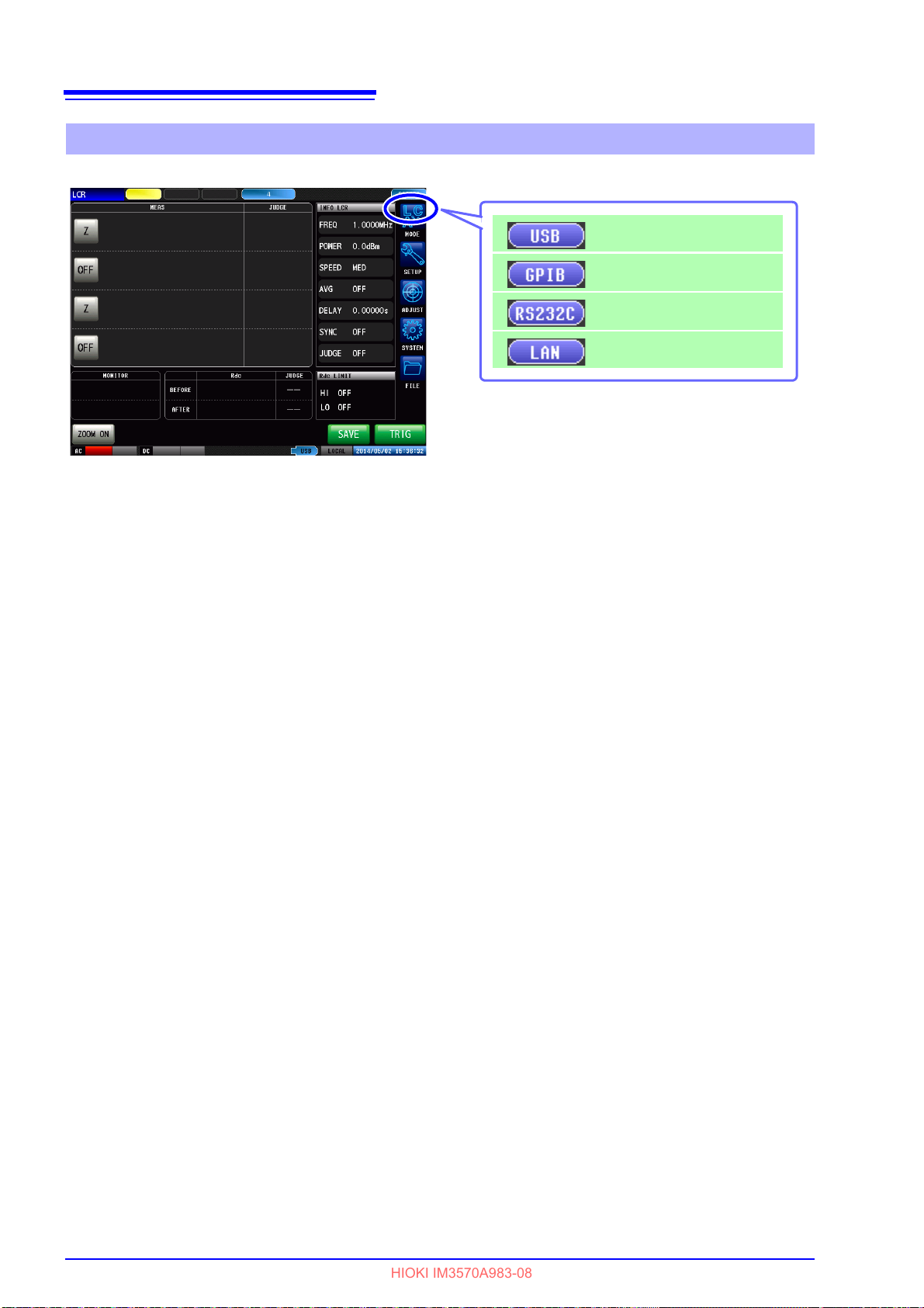
When USB is set
When GP-IB is set
When RS-232C is set
When LAN is set
When printer is set
HIOKI IM3570A983-08
4.1 Overview of Communication
Screen Displayed while Setting Interfaces
When you set an interface, the icon for the set interface is displayed on the right side of the screen.

4.2 USB Settings and Connection
To connect the instrument to a computer the first time, a dedicated USB driver must be installed.
Before connecting the instrument to the computer, install the USB driver.
The USB driver can be downloaded from the bundled CD, or our web site.(http://www.hioki.com)
The USB driver is compatible with the Windows 7 (32-bit, 64-bit version), Windows 8 (32-bit, 64-bit
version), Windows 10 (32-bit, 64-bit version), and Windows 11 (64-bit version) operating systems.
Additionally, do not put the computer into the sleep state while the instrument is connected to the
computer.
You can configure the setting from any of mode, mode, and mode.
Procedure
LCR Measurement Screen
Interface Settings
Using the Z3002
Using the Z3001
Press .
USB Setting
Using the Z3000
When an option is connected
HIOKI IM3570A983-08
4.2 USB Settings and Connection
Setting USB
The display will vary with the installed options.
37

38
USB Setting
Select the terminator setting.
CR+LF
CR
Press to confirm the setting.
USB cable
(commercially available product)
Type B
USB interface port of computer
HIOKI IM3570A983-08
4.2 USB Settings and Connection
Connecting the USB Cable
Connect a USB cable (commercially available USB cable) to the USB port of the instrument.

4.3 GP-IB Connection and Settings (when connected to the Z3000)
Recommended cable:
9151-02 GP-IB connection cable (2 m)
You can configure the setting from any of mode, mode, and mode.
Procedure
LCR Measurement Screen
Interface Settings
HIOKI IM3570A983-08
4.3 GP-IB Connection and Settings
(when connected to the Z3000)
Connecting the GP-IB Cable
Connect the GP-IB cable to the GP-IB connector.
39
Setting GP-IB

40
Press .
GPIB Setting
GPIB Setting
Use or to set the GP-IB address.
Select the terminator setting.
LF with EOI
LF with CR+EOI
Press to confirm the setting.
HIOKI IM3570A983-08
4.3 GP-IB Connection and Settings (when connected to the Z3000)

4.4 RS-232C Connection and Settings (when connected to the Z3001)
Male 9-pin D-sub
#4-40 attaching screws
To connect the instrument to a controller (DTE), use a crossover cable
compatible with the connectors on both the instrument and the controller.
The I/O connector is a DTE (Data Terminal Equipment) configuration.
6 7 8 9
1 2 3 4 5
HIOKI IM3570A983-08
4.4 RS-232C Connection and Settings
(when connected to the Z3001)
Connecting the RS-232C Cable
Connect the RS-232C cable to the RS-232C connector.
(Recommended cable: 9637 RS-232C cable)
41
Connector (D-sub)
Pin No.
1Unused
2 Received Data 104 BB RD RxD
3 Transmitted Data 103 BA SD TxD
4 Data Terminal Ready 108/2 CD ER DTR
5 Signal Ground 102 AB SG GND
6 Unused
7 Request to Send 105 CA RS RTS
8 Clear to Send 106 CB CS CTS
9Unused
Interchange Circuit
Name
CCITT
Circuit No.
EIA
Abbreviation
Example: Connecting to a DOS/V PC
Specification: D-sub 9-pin female and female connector, reverse connection
JIS
Abbreviation
Common
Abbreviation
Hardware control will not work properly if you use a cable that has CA(RTS) and CB(CTS)
short-circuited.

42
Procedure
LCR Measurement Screen
Interface Settings
You can configure the setting from any of mode, mode, and mode.
Press .
RS-232C Settings
Press to confirm the setting.
RS-232C Settings
Select the handshake setting.
No flow control
Hardware (RTS/CTS control)
Software (XON/XOFF control)
Hardware + software
Select the terminator setting.
CR+LF
CR
Select the baud rate setting.
HIOKI IM3570A983-08
4.4 RS-232C Connection and Settings (when connected to the Z3001)
Setting RS-232C

4.5 LAN Settings and Connection (when connected to the Z3002)
• Make these settings before connecting to a network. Changing settings while connected can
duplicate IP addresses of other network devices, and incorrect address information may otherwise be presented to the network.
• The instrument does not support DHCP (automatic IP address assignment) on a network.
Setting Items
Network Environment Configuration
IP Address _________._________._________._________
Subnet Mask _________._________._________._________
Default Gateway _________._________._________._________
HIOKI IM3570A983-08
4.5 LAN Settings and Connection
(when connected to the Z3002)
LAN Settings
You can perform command control using the TCP/IP protocol.
Set the instrument to match your network environment in advance.
Identifies each device connected on a network.
IP address
Subnet mask
Default Gateway
Each network device must be set to a unique address.
The instrument supports IP version 4, with IP addresses indicated as four decimal octets, e.g.,
“192.168.0.1”.
This setting is for separating the IP address into the network address that indicates the network and
the host address that indicates the instrument. On this instrument, the subnet mask is represented as
four decimal numbers separated by “. ” such as “255.255.255.0.”
When the computer and instrument are on different but overlapping networks (subnets), this IP address specifies the device to serve as the gateway between the networks.
If the computer and instrument are connected one-to-one, no gateway is used, and the instrument's
default setting “0.0.0.0” can be kept as is.
43
Example 1. Connecting the instrument to an existing network
When connecting the instrument to an existing network, the network settings need to be confirmed in
advance.
An IP address which is not the same as that of another network device needs to be assigned.
Confirm the following items with the network administrator, and write them down.
Example 2. Connecting multiple instruments to a single computer using a hub
When building a local network with no outside connection, the following private IP addresses are recommended.
Example of private IP address:
IP Address ...............Computer: 192.168.0.100
Subnet Mask............255.255.255.0
Default Gateway ...... OFF(0.0.0.0)
Example 3. Connecting one instrument to a single computer using the 9642 LAN Cable
The 9642 LAN Cable can be used with its supplied connection adapter to connect one instrument to one
computer, in which case the IP address is freely settable. Use the recommended private IP addresses.
IP Address ...............Computer: 192.168.0.100
Subnet Mask............255.255.255.0
Default Gateway ...... OFF(0.0.0.0)
Instrument: 192.168.0.1, 192.168.0.2, 192.168.0.3...
(Set an IP address that differs from that of other network devices.)
Instrument: 192.168.0.1 (Set to a different IP address than the computer.)
44
You can configure the setting from any of mode, mode, and mode.
Procedure
LCR Measurement Screen
Interface Settings
Press .
LAN Settings
LAN Settings
Select the IP address.
HIOKI IM3570A983-08
4.5 LAN Settings and Connection (when connected to the Z3002)
45
IP address Settings
Use or to set the IP address.
Press to confirm the setting.
LAN Settings
Select the subnet mask.
128.000.000.000 255.128.000.000 255.255.128.000 255.255.255.128
192.000.000.000 255.192.000.000 255.255.192.000 255.255.255.192
224.000.000.000 255.224.000.000 255.255.224.000 255.255.255.224
240.000.000.000 255.240.000.000 255.255.240.000 255.255.255.240
248.000.000.000 255.248.000.000 255.255.248.000 255.255.255.248
252.000.000.000 255.252.000.000 255.255.252.000 255.255.255.252
254.000.000.000 255.254.000.000 255.255.254.000
255.000.000.000 255.255.000.000 255.255.255.000
(Initial setting)
Subnet mask Settings
Use or to set the subnet mask,
and press to confirm the setting.
Any of the following 30 subnet masks can be set for the instrument.
HIOKI IM3570A983-08
4.5 LAN Settings and Connection (when connected to the Z3002)
46
LAN Settings
Select the default gateway.
If the default gateway does not need to be set, for
example, when connecting the instrument and
computer on a one-to-one basis using a cross cable, leave this set to OFF.
Default gateway Settings
Use or to set the default gate-
way.
Press to confirm the setting.
LAN Settings
Select the port number.
HIOKI IM3570A983-08
4.5 LAN Settings and Connection (when connected to the Z3002)
47
Port number Settings
Use or to set the port number to
use for communication commands.
Press to confirm the setting.
Settable range : 1024 to 65535
LAN Settings
Select the terminator setting.
CR+LF
CR
Press to confirm the setting.
HIOKI IM3570A983-08
4.5 LAN Settings and Connection (when connected to the Z3002)
48
On: Performing communication with 100BASE.
Off: Performing communication with 10BASE.
Flashes when data is being exchanged.
SPEED LED
RX/TX LED
The MAC address of the LAN is displayed
above the serial number.
You can also check it on the instrument
screen.
See: “Checking the Version of the Instru-
ment” in the instruction manual.
LAN interface
Crossover adapter
Connecting with the 9642 LAN Cable and crossover adapter (supplied with the 9642)
1
Connect the LAN Cable to the
crossover adapter.
Connect the crossover adapter to
the LAN interface on the instrument.
2
Connect the LAN Cable to the
100BASE-TX connector on the PC.
3
HIOKI IM3570A983-08
4.5 LAN Settings and Connection (when connected to the Z3002)
Connecting a LAN Cable
Use a LAN cable to connect the instrument and computer.
Required items:
When connecting the instrument to an existing network (prepare any of the following):
• Straight-through Cat 5, 100BASE-TX-compliant Ethernet cable (up to 100 m, commercially available).
For 10BASE communication, a 10BASE-T-compliant cable may also be used.
• Hioki 9642 LAN Cable (option)
(A cross adapter cannot be used.)
When connecting one instrument to a single computer (prepare one of the following):
• 100BASE-TX-compliant cross-over cable (up to 100 m)
• 100BASE-TX-compliant straight-through cable with cross-over adapter (up to 100 m)
• Hioki 9642 LAN Cable (option)
When connecting the instrument to a single computer (connect the instrument to the computer)

49
All of the keys except are disabled.
Remote Mode State
Procedure
Press to return to the normal state
(local state).
1
The measurement screen is redisplayed.
Local State
LCR Measurement Screen
HIOKI IM3570A983-08
4.6 Remote Mode
4.6 Remote Mode
When you connect a device to an interface and start communication, the mode becomes remote mode
(remote operation state) and the keys on the LCD are disabled.
Canceling Remote Mode

50
HIOKI IM3570A983-08
4.6 Remote Mode

51
USB communication (p. 53)
LAN communication (p. 55)
GP-IB communication (when connected to the Z3000) (p. 61)
RS-232C communication (when connected to the Z3001) (p. 63)
HIOKI IM3570A983-08
5.1 Overview of Communication
Model IM7580 Connection and
Setting Chapter 5
5.1 Overview of Communication
You can control the instrument with communication commands from a computer via the USB, GP-IB, RS232C and LAN interfaces.
There are the following four communication methods. To enable communication, the communication conditions need to be set on the instrument.
The instrument is communication class compatible.
Command control using the TCP/IP protocol is possible.
• Commands common to IEEE-488-2 1987 (requirement) can be used.
• The instrument complies with the following standard. (Compliance standard: IEEE-488.1 1987)
• The instrument has been designed with reference to the following standard. (Reference standard:
IEEE-488.2 1987)
• Always turn both devices OFF when connecting and disconnecting an interface
connector. Otherwise, an electric shock accident may occur.
• To avoid damage to the instrument, do not short-circuit the terminal and do not
input voltage to the terminal.
• Failure to fasten the connectors properly may result is sub-specification performance or damage to the equipment.
• To avoid damage, do not disconnect the communications cable while the instrument is
sending or receiving data.
• Use a common ground for both the instrument and the computer. Grounding them to different ground points will result in a potential difference between the instrument's ground
and the computer's ground. If the communications cable is connected while such a potential difference exists, it may result in equipment malfunction or failure.
• Before connecting or disconnecting any communications cable, always turn off the instrument and the computer. Failure to do so could result in equipment malfunction or damage.
• After connecting the communications cable, tighten the screws on the connector securely.
Failure to secure the connector could result in equipment malfunction or damage.
52
When USB is set
When GP-IB is set
When RS-232C is set
When LAN is set
HIOKI IM3570A983-08
5.1 Overview of Communication
Screen Displayed while Setting Interfaces
When you set an interface, the icon for the set interface is displayed on the right side of the screen.
5.2 USB Settings and Connection
To connect the instrument to a computer the first time, a dedicated USB driver must be installed.
Before connecting the instrument to the computer, install the USB driver.
The USB driver can be downloaded from the bundled CD, or our web site.(http://www.hioki.com)
The USB driver is compatible with the Windows 7 (32-bit, 64-bit version), Windows 8 (32-bit, 64-bit
version), Windows 10 (32-bit, 64-bit version), and Windows 11 (64-bit version) operating systems.
Additionally, do not put the computer into the sleep state while the instrument is connected to the
computer.
You can configure the setting from any of mode and mode.
Procedure
LCR Measurement Screen
Interface Settings
Press .
USB Setting
HIOKI IM3570A983-08
5.2 USB Settings and Connection
Setting USB
The display will vary with the installed options.
53

54
USB Setting
Select the terminator setting.
CR+LF
CR
Press to confirm the setting.
USB cable
(commercially available product)
Type B
USB interface port of computer
HIOKI IM3570A983-08
5.2 USB Settings and Connection
Connecting the USB Cable
Connect a USB cable (commercially available USB cable) to the USB port of the instrument.

5.3 LAN Settings and Connection
• Make these settings before connecting to a network. Changing settings while connected can
duplicate IP addresses of other network devices, and incorrect address information may otherwise be presented to the network.
• The instrument does not support DHCP (automatic IP address assignment) on a network.
Setting Items
Network Environment Configuration
IP Address _________._________._________._________
Subnet Mask _________._________._________._________
Default Gateway _________._________._________._________
HIOKI IM3570A983-08
5.3 LAN Settings and Connection
LAN Settings
You can perform command control using the TCP/IP protocol.
Set the instrument to match your network environment in advance.
Identifies each device connected on a network.
IP address
Subnet mask
Default Gateway
Each network device must be set to a unique address.
The instrument supports IP version 4, with IP addresses indicated as four decimal octets, e.g.,
“192.168.0.1”.
This setting is for separating the IP address into the network address that indicates the network and
the host address that indicates the instrument. On this instrument, the subnet mask is represented as
four decimal numbers separated by “. ” such as “255.255.255.0.”
When the computer and instrument are on different but overlapping networks (subnets), this IP address specifies the device to serve as the gateway between the networks.
If the computer and instrument are connected one-to-one, no gateway is used, and the instrument's
default setting “0.0.0.0” can be kept as is.
55
Example 1. Connecting the instrument to an existing network
When connecting the instrument to an existing network, the network settings need to be confirmed in
advance.
An IP address which is not the same as that of another network device needs to be assigned.
Confirm the following items with the network administrator, and write them down.
Example 2. Connecting multiple instruments to a single computer using a hub
When building a local network with no outside connection, the following private IP addresses are recommended.
Example of private IP address:
IP Address ...............Computer: 192.168.0.100
Instrument: 192.168.0.1, 192.168.0.2, 192.168.0.3...
(Set an IP address that differs from that of other network devices.)
Subnet Mask............255.255.255.0
Default Gateway ...... OFF(0.0.0.0)
Example 3. Connecting one instrument to a single computer using the 9642 LAN Cable
The 9642 LAN Cable can be used with its supplied connection adapter to connect one instrument to one
computer, in which case the IP address is freely settable. Use the recommended private IP addresses.
IP Address ...............Computer: 192.168.0.100
Instrument: 192.168.0.1 (Set to a different IP address than the computer.)
Subnet Mask............255.255.255.0
Default Gateway ...... OFF(0.0.0.0)

56
You can configure the setting from any of mode and mode.
Procedure
LCR Measurement Screen
Interface Settings
Press .
LAN Settings
LAN Settings
Select the IP address.
HIOKI IM3570A983-08
5.3 LAN Settings and Connection

57
IP address Settings
Use or to set the IP address.
Press to confirm the setting.
LAN Settings
Select the subnet mask.
128.000.000.000 255.128.000.000 255.255.128.000 255.255.255.128
192.000.000.000 255.192.000.000 255.255.192.000 255.255.255.192
224.000.000.000 255.224.000.000 255.255.224.000 255.255.255.224
240.000.000.000 255.240.000.000 255.255.240.000 255.255.255.240
248.000.000.000 255.248.000.000 255.255.248.000 255.255.255.248
252.000.000.000 255.252.000.000 255.255.252.000 255.255.255.252
254.000.000.000 255.254.000.000 255.255.254.000
255.000.000.000 255.255.000.000 255.255.255.000
(Initial setting)
Subnet mask Settings
Use or to set the subnet mask,
and press to confirm the setting.
Any of the following 30 subnet masks can be set for the instrument.
HIOKI IM3570A983-08
5.3 LAN Settings and Connection

58
LAN Settings
Select the default gateway.
If the default gateway does not need to be set, for
example, when connecting the instrument and
computer on a one-to-one basis using a cross cable, leave this set to OFF.
Default gateway Settings
Use or to set the default gateway.
Press to confirm the setting.
LAN Settings
Select the port number.
HIOKI IM3570A983-08
5.3 LAN Settings and Connection

59
Port number Settings
Use or to set the port number to
use for communication commands.
Press to confirm the setting.
Settable range : 1024 to 65535
LAN Settings
Select the terminator setting.
CR+LF
CR
Press to confirm the setting.
HIOKI IM3570A983-08
5.3 LAN Settings and Connection
60
On: Link up
Off: Link down
Blinking: Sending or receiving data
On (Green) :1000BASE
On (Orange) :100BASE
Off:10BASE
LINK UP LED
SPEED LED
The MAC address of the LAN is displayed below the serial number.
You can also check it on the instrument screen.
See: “Checking the Version of the Instrument” in the instruction
manual.
LAN interface
Crossover adapter
Connecting with the 9642 LAN Cable and crossover adapter (supplied with the 9642)
1
Connect the LAN Cable to the
crossover adapter.
Connect the crossover adapter to
the LAN interface on the instrument.
2
Connect the LAN Cable to the
100BASE-TX connector on the PC.
3
HIOKI IM3570A983-08
5.3 LAN Settings and Connection
Connecting a LAN Cable
Use a LAN cable to connect the instrument and computer.
Required items:
When connecting the instrument to an existing network (prepare any of the following):
• Straight-through Cat 5, 1000BASE-T-compliant Ethernet cable (up to 100 m, commercially available).
For 100BASE/10BASE communication, a 100BASE-TX/10BASE-T-compliant cable may also be used.
• Hioki 9642 LAN Cable (option)
(A cross adapter cannot be used.)
When connecting one instrument to a single computer (prepare one of the following):
• 1000BASE-T-compliant cross-over cable (up to 100 m)
• 1000BASE-T-compliant straight-through cable with cross-over adapter (up to 100 m)
• Hioki 9642 LAN Cable (option)
When connecting the instrument to a single computer (connect the instrument to the computer)
5.4 GP-IB Connection and Settings (when connected to the Z3000)
Recommended cable:
9151-02 GP-IB connection cable (2 m)
You can configure the setting from any of mode and mode.
Procedure
LCR Measurement Screen
Interface Settings
HIOKI IM3570A983-08
5.4 GP-IB Connection and Settings
(when connected to the Z3000)
Connecting the GP-IB Cable
Connect the GP-IB cable to the GP-IB connector.
61
Setting GP-IB
62
Press .
GPIB Setting
GPIB Setting
Use or to set the GP-IB address.
Select the terminator setting.
LF with EOI
LF with CR+EOI
Press to confirm the setting.
HIOKI IM3570A983-08
5.4 GP-IB Connection and Settings (when connected to the Z3000)
5.5 RS-232C Connection and Settings (when connected to the Z3001)
Male 9-pin D-sub
#4-40 attaching screws
To connect the instrument to a controller (DTE), use a crossover cable
compatible with the connectors on both the instrument and the controller.
The I/O connector is a DTE (Data Terminal Equipment) configuration.
6 7 8 9
1 2 3 4 5
HIOKI IM3570A983-08
5.5 RS-232C Connection and Settings
(when connected to the Z3001)
Connecting the RS-232C Cable
Connect the RS-232C cable to the RS-232C connector.
(Recommended cable: 9637 RS-232C cable)
63
Connector (D-sub)
Pin No.
1Unused
2 Received Data 104 BB RD RxD
3 Transmitted Data 103 BA SD TxD
4 Data Terminal Ready 108/2 CD ER DTR
5 Signal Ground 102 AB SG GND
6 Unused
7Unused
8 Unused
9Unused
Interchange Circuit
Name
CCITT
Circuit No.
EIA
Abbreviation
Abbreviation
Example: Connecting to a DOS/V PC
Specification: D-sub 9-pin female and female connector, reverse connection
JIS
Common
Abbreviation
64
Procedure
LCR Measurement Screen
Interface Settings
You can configure the setting from any of mode and mode.
Press .
RS-232C Settings
Press to confirm the setting.
RS-232C Settings
Select the handshake setting.
No flow control
Software (XON/XOFF control)
Select the terminator setting.
CR+LF
CR
Select the baud rate setting.
HIOKI IM3570A983-08
5.5 RS-232C Connection and Settings (when connected to the Z3001)
Setting RS-232C
65
All of the keys except are disabled.
Remote Mode State
Procedure
Press to return to the normal state
(local state).
1
The measurement screen is redisplayed.
Local State
LCR Measurement Screen
HIOKI IM3570A983-08
5.6 Remote Mode
5.6 Remote Mode
When you connect a device to an interface and start communication, the mode becomes remote mode
(remote operation state) and the keys on the LCD are disabled.
Canceling Remote Mode

66
HIOKI IM3570A983-08
5.6 Remote Mode
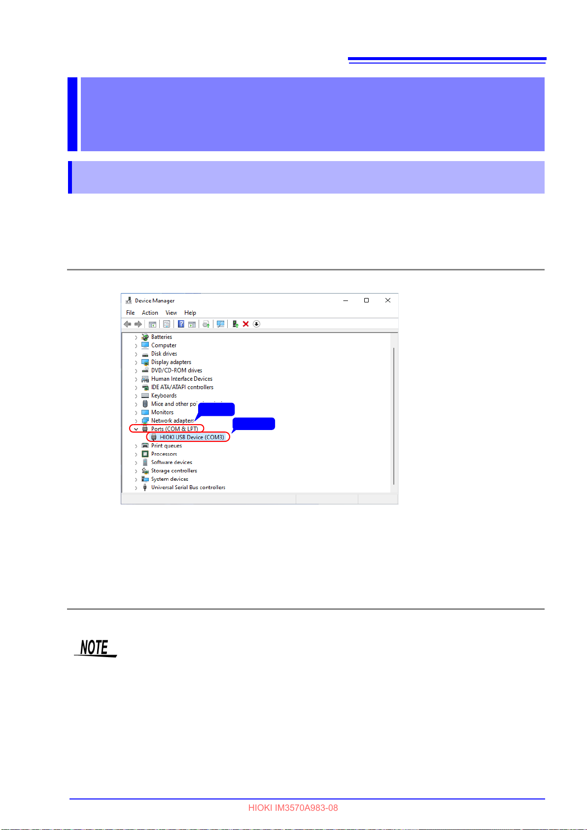
A1
Check
Check the COM number on the right of “HIOKI IM3570 Impedance Analyzer” port in the [Ports
(COM & LPT)] list.
• When the IM3523, IM3523A, IM3533, IM3533-01, IM3590 and IM7580 : Check the COM
number to the right of “HIOKI USB Device” in the [Ports (COM & LPT)] list.
• When the IM3570 : Check the COM number to the right of “HIOKI IM3570 Impedance Analyzer” in the [Ports (COM & LPT)] list.
Click
HIOKI IM3570A983-08
Appendix 1 Checking the USB Virtual COM Port
Appendix
Appendix 1 Checking the USB Virtual COM Port
The instrument’s USB interface supports communications-class performance, allowing control operations on
par with RS-232C to be performed from a computer. When you connect the instrument to a computer and set
its interface to USB, it will be recognized as a virtual COM port on the computer.
Device Manager starts.
The procedure to start Device Manager differs depending on the version of the Windows operating system.
For details, refer to Help of the operating system.

A2
HIOKI IM3570A983-08
Appendix 1 Checking the USB Virtual COM Port

HIOKI IM3570A983-08

HIOKI IM3570A983-08

HIOKI IM3570A983-08

HIOKI IM3570A983-08
www.hioki.com/
 Loading...