

Page 1
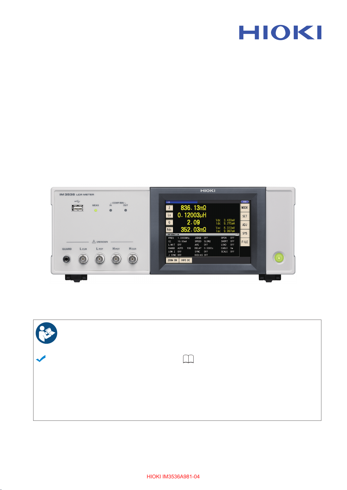
IM3536
HIOKI IM3536A981-04HIOKI IM3536A981-04
LCR METER
Instruction Manual
Aug. 2022 Revised edition 4
IM3536A981-04 22-08H
Read carefully before use.
Keep for future reference.
When using the instrument for the
rst time
Safety Information
Names and Functions of
Parts
Screen Layout and
Operation
p.12 Maintenance and Service p.229
p.20
p.22
Troubleshooting
Error Massage and Error
Display
p.238
EN
[600447564]
Page 2

Contents
HIOKI IM3536A981-04HIOKI IM3536A981-04
Introduction ................................................ 1
Verifying Package Contents ..................... 2
Measurement Process .............................. 8
Safety Information ................................... 12
Operating Precautions ............................ 14
1 Overview 19
1.1 Product Overview and
Features .......................................... 19
1.2 Names and Functions of Parts ..... 20
1.3 Screen Layout and Operation ....... 22
Screen transition diagram ...........................22
Viewing measured values
(Measurement screen) ................................24
Select the measurement mode
(MODE screen) ...........................................26
Setting detailed settings such as
measurement conditions (SET screen) ......27
Checking measurement condition
settings information .....................................28
Conguring correction functionality
(ADJ screen) ...............................................29
Conguring the instrument’s interfaces,
setting the time and date, and checking
the system (SYS screen) ............................30
Displaying and manipulating les on the
USB ash drive (FILE screen) ....................31
2 Measurement
Preparations 33
2.1 Preparation Flowchart ................... 33
2.2 Pre-operation Inspection ............... 35
2.3 Connecting the Power Cord .......... 36
2.4 Connecting the Measurement
Cables, Probes, or Fixture ............. 37
2.5 Turning the Instrument On and
Off .................................................... 38
2.6 Setting the Date and Time ............. 40
3.4 Setting Measurement
Conditions (Basic Settings) .......... 46
Required settings ........................................47
User-congurable settings ..........................58
Measurement and data acquisition
timing ..........................................................69
When measuring conductivity and
permittivity ...................................................71
3.5 Judging Measurement Results ..... 72
Setting the judgment mode .........................73
Conguring comparator function
settings (judging measurement results
based on one judgment standard) ..............73
Conguring BIN function settings
(judging measured values based on
multiple judgment standards) ......................78
3.6 Setting Application Settings ......... 83
Range synchronization
(setting measurement conditions for
individual measurement ranges) .................83
Waveform averaging function
(increasing measurement precision or
measurement speed) ..................................86
High-Z reject function
(detecting contact errors during
2-terminal measurement) ............................88
Contact check function
(detecting poor contact with the sample
during 4-terminal measurement) .................89
Memory function
(saving measurement results) ....................91
Number of effective digits of the
measurement value ....................................94
LCD display auto-off
(power-saving mode) ..................................95
Key tones and judgment tones ...................96
Key-lock function
(disabling key operation) .............................97
4 Using Continuous
Measurement Mode 99
3 Performing
3.1 Setting Display Parameters ........... 41
3.2 Viewing Measured Values.............. 44
3.3 Enlarging Display of
IM3536A981-04
Measurements in LCR
Mode 41
To perform DC measurement
(DC resistance measurement) ....................42
Measurement Values ...................... 45
4.1 Setting Which Panels to Use in
Continuous Measurement ............. 99
4.2 Performing Continuous
Measurement ................................ 100
4.3 Checking Continuous
Measurement Results .................. 100
4.4 Changing the Display Timing
Setting
(When You Wish to Shorten the
Screen Update Interval) ............... 101
i
Page 3

Contents
HIOKI IM3536A981-04HIOKI IM3536A981-04
4.5 Setting the LCD Display AutoOff
(When You Wish to Save the
Power) ........................................... 102
5 Error Correction 103
5.1 Setting the Cable Length
(Cable Length Correction) ........... 104
5.2 Open Correction ........................... 105
Before performing open correction ...........105
All correction .............................................106
Spot correction .......................................... 11 0
5.3 Short Correction ............................112
Before performing open correction ........... 112
All correction ............................................. 113
Spot correction .......................................... 11 4
5.4 If Open or Short Correction
Fails to Complete Normally ..........116
5.5 Disabling Open and Short
Correction Values ..........................118
5.6 Load Correction
(Correcting Values to Match
Reference Values) .........................119
Procedures for the load correction ............120
To reset the correction condition
settings .....................................................127
When load correction fails to complete
normally ....................................................127
Disabling load correction ..........................128
5.7 Correcting Measured Values
with a User-Specied Correction
Coefcient
(Correlation Correction) .............. 129
6 Saving and Loading
Measurement
Condition and
Correction Value Data 131
6.1 Saving Measurement Conditions
and Correction Values
(Panel Save Function) .................. 132
6.2 Loading Measurement
Conditions and Correction
Values (Panel Load Function) ..... 136
6.3 Changing a Panel Name .............. 137
6.4 Deleting a Panel ........................... 138
7 Setting the System 139
7.1 Setting the Interface
(Controlling the Instrument from
a Computer) .................................. 140
7.2 Checking the Version of the
Instrument ..................................... 140
7.3 Testing the System
(Self Diagnosis) ............................ 141
Panel test ..................................................141
Panel calibration .......................................142
Testing the screen display status and
LED status ................................................142
ROM/RAM test ..........................................143
Testing EXT I/O input/output signals .........143
8 Using USB Flash Drive
(Saving and Loading
Data) 145
8.1 Inserting and Removing a USB
Flash Drive .................................... 146
8.2 Checking the Contents of Files
on a USB Flash Drive ................... 147
8.3 Formatting a USB Flash Drive .... 148
8.4 Saving Measurement Data .......... 149
Saving measurement data in text .............149
Saving a copy of the screen .....................158
To specify the save folder .........................160
8.5 Saving Settings Data ................... 161
Saving instrument settings other than
panels .......................................................161
Save all instrument settings including
panels (ALL SAVE function) ...................... 162
8.6 Loading Instrument Settings ...... 163
Loading settings les or panel les ...........163
Loading settings les including panel
les (ALL LOAD function) .........................164
8.7 Checking the Contents of a File . 165
8.8 Deleting Files and Folders .......... 166
8.9 Creating Folders ........................... 167
8.10 Displaying the USB Flash Drive
Information ................................... 168
9 External Control 169
9.1 External Input/Output Connector
and Signals ................................... 170
Instrument connector and supported
connectors ................................................170
Instrument connector signal assignments 170
Input (IN) signal function details ...............175
ii
Page 4

Contents
HIOKI IM3536A981-04HIOKI IM3536A981-04
BCD mode function details .......................176
Output signals when errors occur .............178
9.2 Example Measurement Timing
(Timing Charts) ............................. 179
9.3 Internal Circuitry .......................... 184
Circuit diagrams ........................................184
Electrical specications .............................186
Connection examples ...............................186
9.4 External I/O Settings .................... 188
Setting the delay time (from judgment
result output to EOM
judgment result reset operation ................189
Disabling the trigger input during
measurement and setting the trigger
input effective edge ...................................190
Setting the E
output time ................................................191
Outputting measured values (switching
to BCD mode) (LCR mode only) ...............192
―――
output) and
________
OM output method and
9.5 External Control Q&A .................. 193
9.6 Measurement Using a Computer 194
10 Specications 195
10.1 General Specications ................ 195
10.2 Environmental and Safety
Specications ............................... 200
10.3 Accessories and Options ............ 201
10.4 Function Specications ............... 201
10.5 Interfaces ...................................... 213
10.6 Measurement Range and
Accuracy ....................................... 215
10.7 About Measurement Times and
Measurement Speed .................... 225
11 Maintenance and
Service 229
11.4 Discarding the Instrument ........... 243
Appendix Appx.1
Appx. 1 Measurement
Parameters and
Calculation Formula ........ Appx.1
Appx. 2 Measurement of High
Impedance
Components ..................... Appx.3
Appx. 3 Measurement of In-
circuit Components ......... Appx.4
Appx. 4 Countermeasures
Against Incorporation of
External Noise .................. Appx.5
Countermeasures against incorporation
of noise from the power line .................Appx.5
Countermeasures against noise from
the measurement cables .....................Appx.6
Appx. 5 Supplying DC Bias ........... Appx.6
How to supply a DC bias voltage .........Appx.7
How to supply a DC bias current .........Appx.8
Appx. 6 The Residual Charge
Protection Function ......... Appx.9
Appx. 7 Series Equivalent Circuit
Mode and Parallel
Equivalent Circuit
Mode ............................... Appx.10
Appx. 8 Open Correction and
Short Correction .............Appx.11
Appx. 9 Attaching Rack-
Mounting Hardware to
the Instrument ................ Appx.12
Appx. 10 Dimensional Diagram .... Appx.14
Appx. 11 Initial Settings Table ...... Appx.15
Appx. 12 Device Compliance
Statement ....................... Appx.23
11.1 Calibration, Inspection, Repair,
11.2 Troubleshooting ........................... 231
11.3 Error Massage and Error
and Cleaning ................................. 229
Calibrations ...............................................229
Inspection and repair ................................229
Replaceable parts and operating
lifetimes .....................................................229
Transporting the instrument ......................230
Cleaning ....................................................230
Before returning for repair .........................231
Initializing (system reset) ..........................236
Performing a full reset
(If you are unable to perform a system
reset) .........................................................237
Display .......................................... 238
Index Ind.1
iii
Page 5

Contents
HIOKI IM3536A981-04HIOKI IM3536A981-04
iv
Page 6
Introduction
HIOKI IM3536A981-04HIOKI IM3536A981-04
Thank you for purchasing the Hioki IM3536 LCR Meter. To obtain maximum performance from the
instrument, please read this manual rst, and keep it handy for future reference.
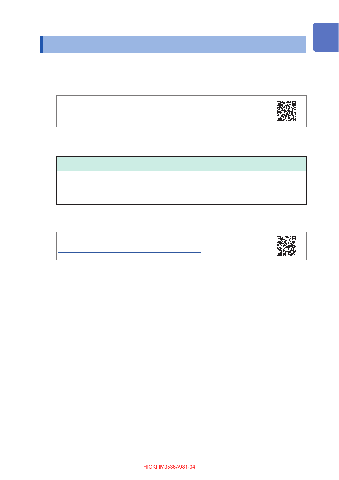
Latest instruction manual
The contents of this manual are subject to change, for example as a result of
product improvements or changes to specications.
The latest edition can be downloaded from Hioki’s website.
https://www.hioki.com/global/support/download
This instrument comes with the following documentation. Please refer to these resources as
necessary in light of your specic application.
Type Manual contents
Instruction Manual
(this document)
Communication
Instruction Manual
Detailed information about functionality and
operation; specications
Explanation of communications commands for
controlling the instrument
Printed
edition
–
Product registration
Register your product in order to receive important product information.
https://www.hioki.com/global/support/myhioki/registration
Target audience
This manual has been written for use by individuals who use the product in question or who teach
others to do so. It is assumed that the reader possesses basic electrical knowledge (equivalent to
that of someone who graduated from the electrical program at a technical high school).
Trademarks
Microsoft and Windows are either registered trademarks or trademarks of Microsoft Corporation in
the United States and other countries.
CD edition
–
1
Page 7
Verifying Package Contents
HIOKI IM3536A981-04HIOKI IM3536A981-04
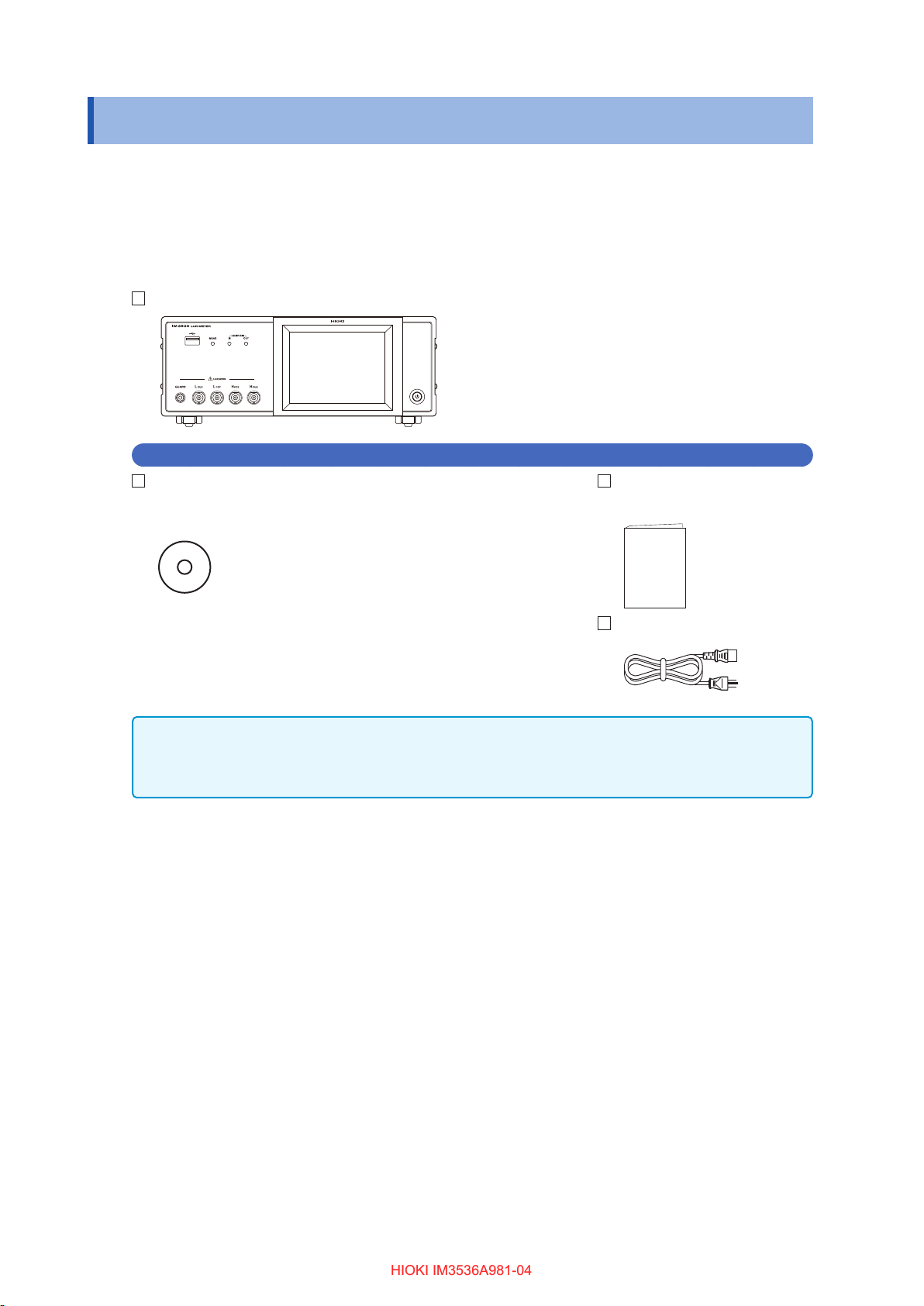
Verifying Package Contents
When you receive the instrument, inspect it carefully to ensure that no damage occurred during
shipping. In particular, check the accessories, panel switch, button, and connectors. If damage
is evident, or if it fails to operate according to the specications, contact your authorized Hioki
distributor or reseller.
Conrm that these contents are provided.
IM3536 LCR Meter ×1
Accessories
LCR Application Disc ×1
(including the PDF edition of Communications Instruction Manual,
explanations of communications commands, and the USB driver)
Instruction Manual
(This document) ×1
The latest version can be downloaded from our website
Power cord ×1
• Measurement cable and xture are not supplied with the instrument as standard equipment. You should
order them separately, according to requirements.
See “Options (reference: open and short correction states)” (p. 3).
• The instrument ships from the factory congured as described in”Appx. 11 Initial Settings Table” (p. Appx.15).
Precautions when transporting the instrument
Store the packaging in which the instrument was delivered, as you will need it when transporting
the instrument.
2
Page 8
Verifying Package Contents
HIOKI IM3536A981-04HIOKI IM3536A981-04
Options (reference: open and short correction states)
The following options are available for the instrument. Contact your authorized Hioki distributor
or reseller when ordering. Options are subject to change. Check Hioki’s website for the latest
information.
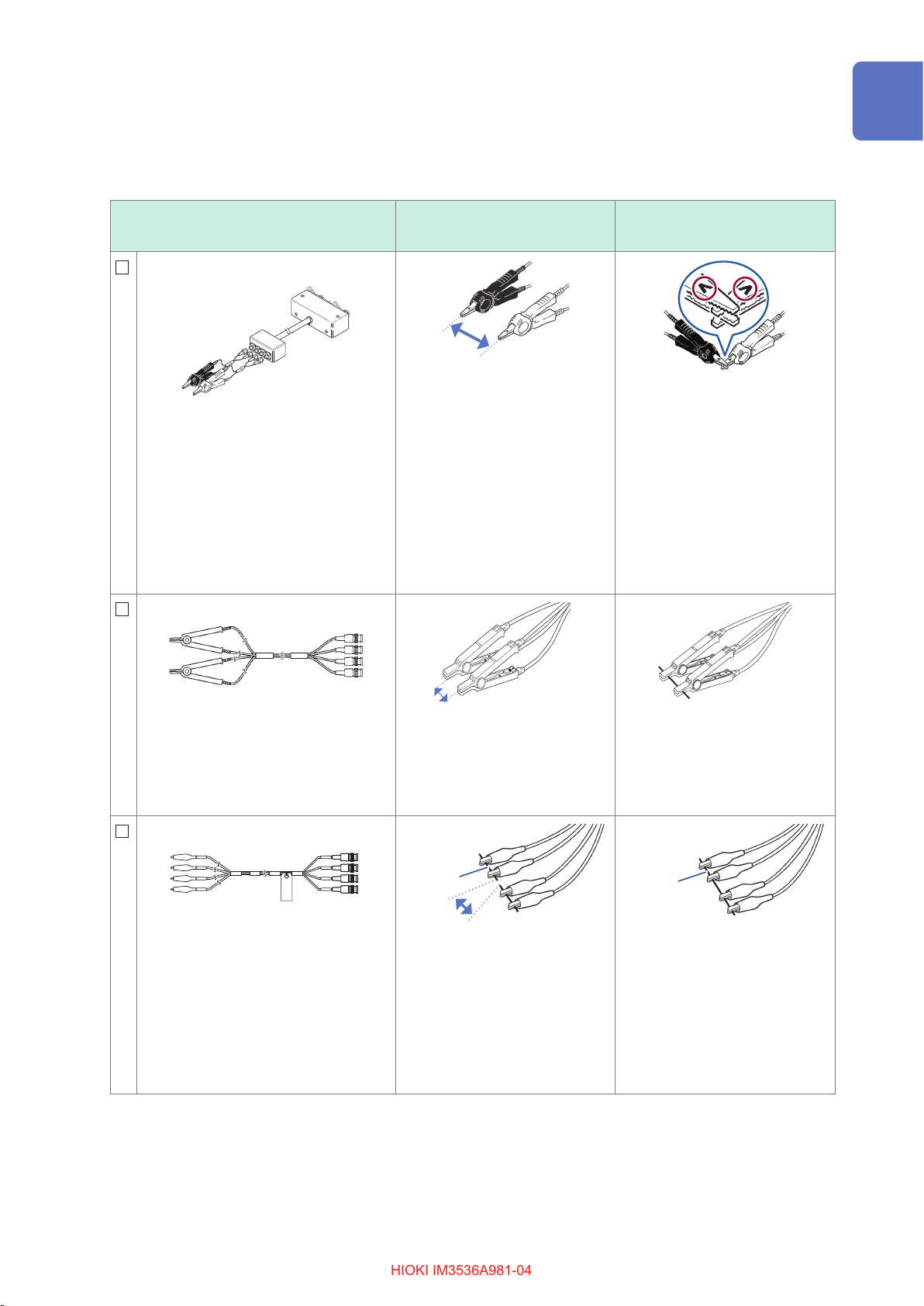
Probe type (cord length: 1 m)
L2000 4-Terminal Probe
Measurable range: DC to 8 MHz
Maximum applied voltage: ±42 V peak
(AC+DC)
Maximum applied current: ±1 A peak
(AC+DC)
Measurement terminal hole diameter:
0.3 mm to 5 mm
Alligator-clip-type measurement cables.
These general-purpose dual-electrode
clips t a wide range of conductor
thicknesses.
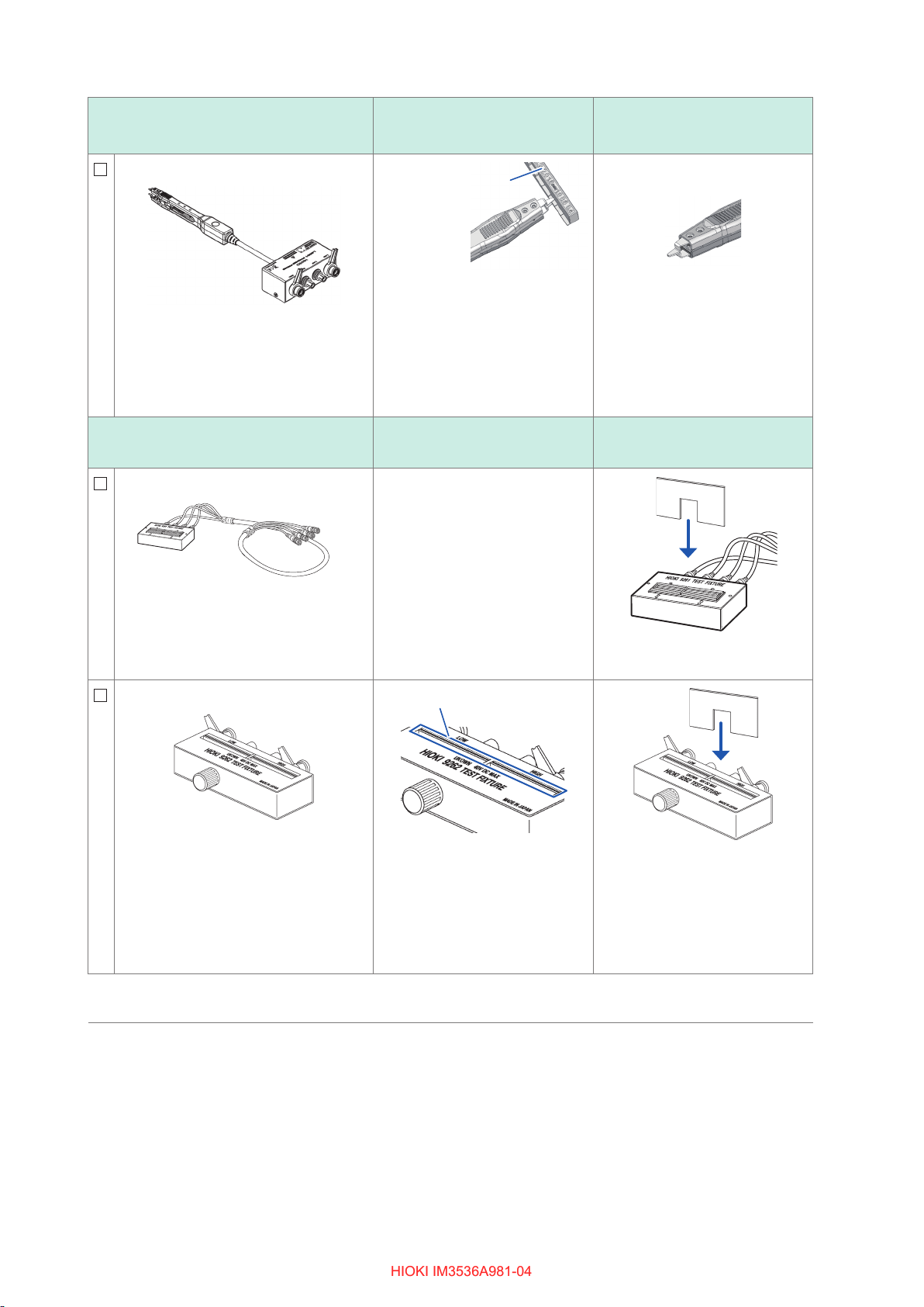
9140-10 4-Terminal Probe
Open state during open
correction
Width of the measurement
sample
Close the tips of the probes and
place the probes so that they are
as far apart as the width of the
measurement sample.
Shorted state during short
correction
L
POT
L
CUR
Clamp the probe tips together
with the V mark facing up.
H
POT
H
CUR
Measurable range: DC to 200 kHz
Maximum applied voltage: ±42 V peak
(AC+DC)
Maximum applied current: ±1 A peak
(AC+DC)
Measurement terminal hole diameter:
0.3 mm to 5 mm
9500-10 4-Terminal Probe
Measurable range: DC to 200 kHz
Maximum applied voltage: DC±40 [42
V peak (Measurement signal + bias
voltage)]
Maximum applied current: 1 A peak
(Measurement signal + bias voltage)
Measurement terminal hole diameter:
0.3 mm to 2 mm
Rubber-sheathed alligator clip type
Width of the measurement
sample
Close the tips of the probes and
place the probes so that they are
as far apart as the width of the
measurement sample.
Red (High)
Metal wire
Width of the
measurement
Black (Low)
sample
Clamp a short piece of metal wire
with the H
(red) and the L
CUR
and H
CUR
POT
and L
terminals
POT
terminals (black) of the probes
so that they are as far apart as
the width of the measurement
sample.
Clamp the probes on the short
bar.
Red (High)
Metal wire
Black (Low)
Clamp a short piece of metal wire
in the following probe terminal
order: H
CUR
, H
POT
, L
POT
, L
CUR
.
3
Page 9
Verifying Package Contents
HIOKI IM3536A981-04HIOKI IM3536A981-04
Probe type (cord length: 1 m)
L2001 Pincher Probe
Measurable range: DC to 8 MHz
Maximum applied voltage: ±30 V DC
Space between tip electrodes: 0 mm to
approx. 6 mm
Pincer type
*1
Test xture types
9261-10 Test Fixture
Open state during open
correction
Gradations on open
correction xture
Clamp the tip of the pincers
at the open correction xture
gradation (using the same value
as the length of the measurement
sample), taking care to insert the
pincers all the way.
(For sample 1005, the length is
1.0 mm.)
Open state during open
correction
Connect the 9261-10 and the
instrument with the connection
cable (do not clamp anything to
the xture).
Shorted state during short
correction
Close the tip of the pincers.
Shorted state during short
correction
Measurable range: DC to 8 MHz
Maximum applied voltage: ±40 V DC
Measurement terminal hole diameter:
0.3 mm to 1.5 mm
Cord length: 1 m
9262 Test Fixture
*1
In contact
Insert the short bar all the way
into the sample mounting area.
Measurable range: DC to 8 MHz
Maximum applied voltage: ±40 V DC
Measurable sample dimensions:
Turn the knob clockwise to tighten
the sample mounting area.
Insert the short bar all the way
into the sample mounting area.
Lead diameter of φ0.3 mm to φ2 mm
Lead pitch of 5 mm or more
This fixture is for measuring lead
components. (less than 10 m
residual
Ω
resistance after zero adjustment)
*1: Although the test xture appears to use a four-terminal setup, two terminals provide contact with the sample
since H
POT
and H
as well as L
CUR
POT
and L
are connected inside the xture and probe.
CUR
4
Page 10
Verifying Package Contents
ショート
オープン
HIOKI IM3536A981-04HIOKI IM3536A981-04
Test xture types
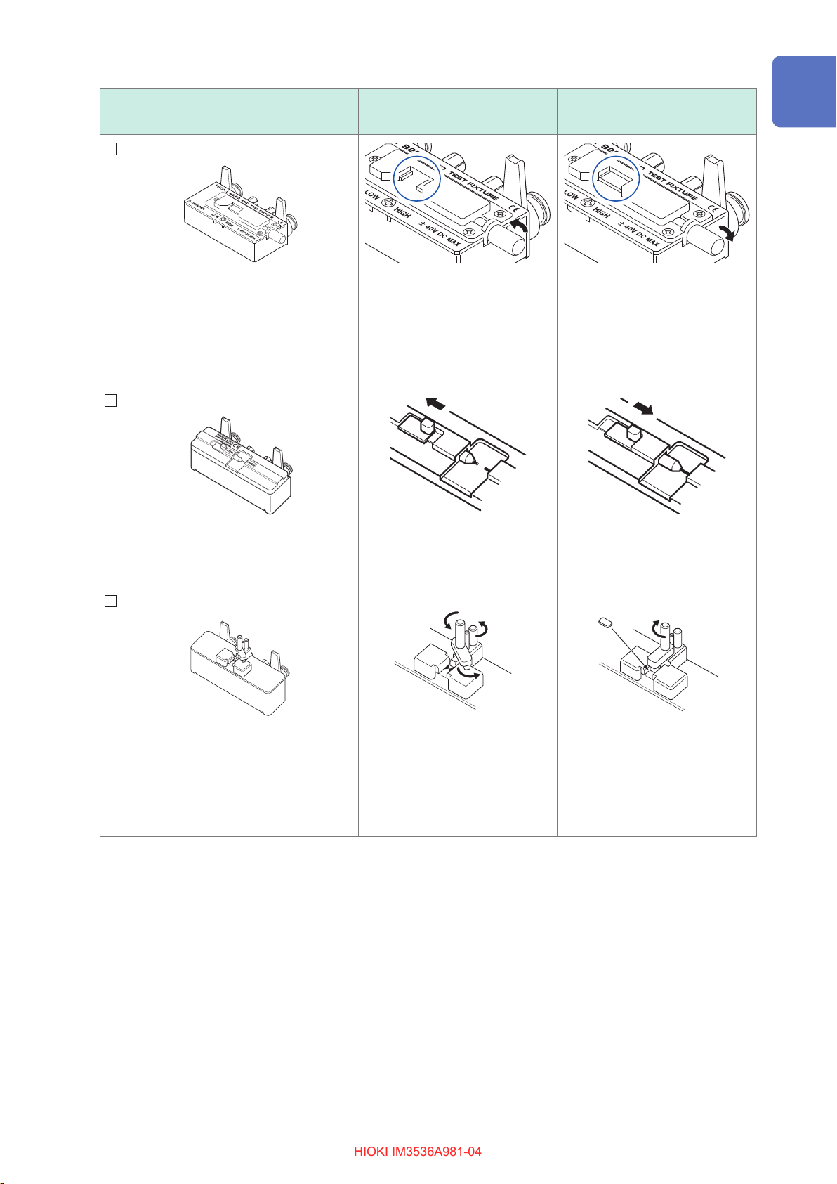
9263 SMD Test Fixture
Measurable range: DC to 8 MHz
Maximum applied voltage: ±40 V DC
Measurable sample dimensions: Test
sample width of 1 mm to 10 mm
This fixture is for measuring chip
components. (less than 10 m
resistance after zero adjustment)
9677 SMD Test Fixture
*1
residual
Ω
*1
Open state during open
correction
Turn the knob counterclockwise
to open the high and low
electrodes (use the width of the
measurement sample as the open
spacing).
Shorted state during short
correction
Turn the knob clockwise to tighten
the high and low electrodes.
Measurable range: DC to 120 MHz
Maximum applied voltage: ±40 V DC
Measurable sample dimensions: Test
sample width of 3.5±0.5 mm or less
9699 SMD Test Fixture
*1
Measurable range: DC to 120 MHz
Maximum applied voltage: ±42 V peak
(AC+DC)
Measurable sample dimensions: Test
sample width of 1 mm to 4 mm
Move the knob to open the high
and low electrodes (use the width
of the measurement sample as
the open spacing).
Turn both knobs counterclockwise
to loosen them (do not place
anything in the sample mounting
area).
Move the knob to close the high
and low electrodes.
Position the included short bar
in the sample mounting area
and turn the knobs clockwise to
secure the measurement sample
in place.
Test sample height of 1.5 mm or less
This xture is for the lower electrode.
*1: Although the test xture appears to use a four-terminal setup, two terminals provide contact with the sample
since H
POT
and H
as well as L
CUR
POT
and L
are connected inside the xture and probe.
CUR
5
Page 11

Verifying Package Contents
HIOKI IM3536A981-04HIOKI IM3536A981-04
Test xture types
IM9100 SMD Test Fixture
Measurable range: DC to 8 MHz
Maximum applied voltage: ±40 V DC
Maximum applied current: 0.15 A rms
(±0.15 A DC)
Measurable sample dimensions:
JIS (EIA): L mm × W mm
0402 (01005) : 0.4 mm × 0.2 mm
0603 (0201) : 0.6 mm × 0.3 mm
1005 (0402) : 1.0 mm × 0.5 mm
For use with SMD components
IM9110 SMD Test Fixture
Measurable range: DC to 1 MHz
Maximum applied voltage:
±42 V peak (AC+DC)
Maximum applied current:
0.15 A rms (±0.15 A DC)
Measurable sample dimensions:
0.25 ±20% × 0.125 ±10% × 0.125
±10% mm (notation base on JIS: 0201)
Open state during open
correction
22
11
Mount the open correction xture
for the 1005 in the test head
measurement area with a pair of
pincers.
1. Move the operating lever
toward CLOSE (MEASURE).
2. Find the position where the
measurement probes switch
between an open state and a
short state.
3. From that position, rotate
the micrometer clockwise
by 0.25 mm (a half turn) for
correction.
See the IM9110 SMD Test Fixture
Instruction Manual to perform
open correction using samples.
Shorted state during short
correction
33
11
1. Remove the template.
2. Mount the short correction
xture in the test head
measurement area, passing
the guide pins through the
holes on the xture.
3. Push the tip of the tip pin
gradually into the short
correction xture.
1. Move the operating lever
toward CLOSE (MEASURE).
2. Find the position where the
measurement probes switch
between open and short
states.
3. From that position, rotate the
micrometer counterclockwise
by 0.1 mm for correction.
See the IM9110 SMD Test Fixture
Instruction Manual to use the
short-compensation jig, which
came with the IM9110.
22
6
Page 12
Verifying Package Contents
HIOKI IM3536A981-04HIOKI IM3536A981-04
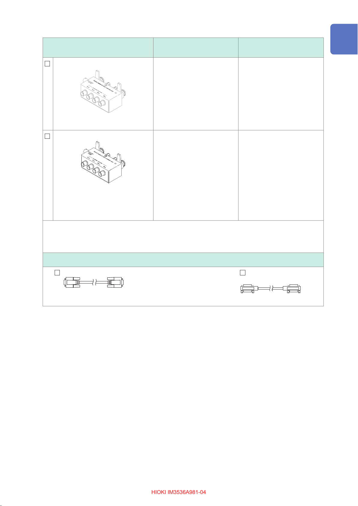
DC Bias Unit
9268-10 DC Bias Voltage Unit
Measurable range: 40 Hz to 8 MHz
Maximum applied voltage: ±40 V DC
9269-10 DC Bias Current Unit
Measurable range: 40 Hz to 2 MHz
(The upper-limit frequency decreases
to 1 MHz for extended measurement
cables.)
Maximum applied current: 2 A DC
*2
Open state during open
correction
Connect the following items to the
9268-10:
• Measurement cables and xture
or probe (in the open correction
state)
• Bias application cable
• External DC bias power supply
(with the 0 V output setting on)
Connect the following items to the
9269-10:
• Measurement cables and xture
or probe (in the open correction
state)
• Bias application cable
• External DC bias power supply
(setting off)
(Do not connect the bias
application cable.)
Shorted state during short
correction
Connect the following items to the
9268-10:
• Measurement cables and xture
or probe (in the short correction
state)
• Bias application cable
• External DC bias power supply
(with the 0 V output setting on)
Connect the following items to the
9269-10:
• Measurement cables and xture
or probe (in the short correction
state)
• Bias application cable
• External DC bias power supply
(setting off)
(Do not connect the bias
application cable.)
*2: When using the DC Bias Unit to perform short correction for ALL, use the instrument to turn off the DC
measurement.
When using the DC Bias Unit, use the instrument to turn on the DC bias function and set the voltage at 0.00 V.
(p. 63)
Connection cords
9637 RS-232C Cable
9-pin to 9-pin cross type, Cord length: 1.8 m
9151-02 GP-IB Connector
Cable
Cord length: 2 m
7
Page 13
Measurement Process
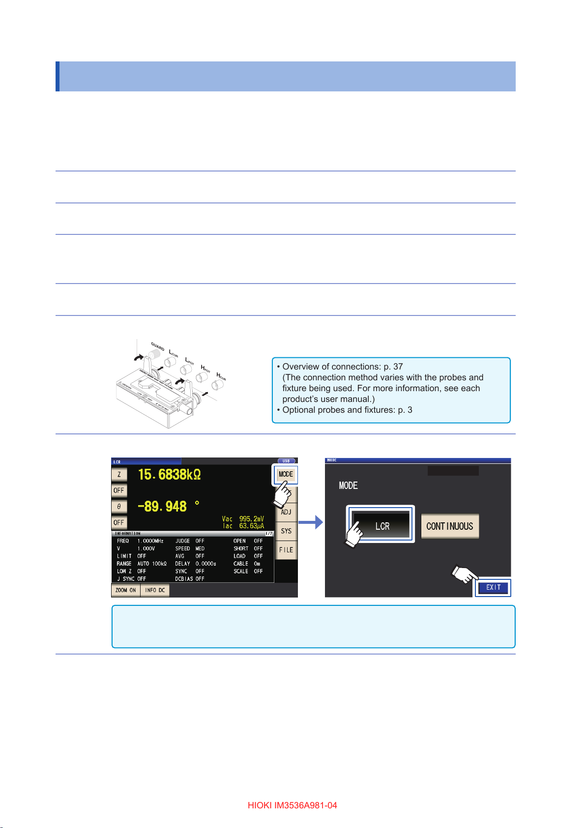
• Overview of connections: p. 37
(The connection method varies with the probes and
xture being used. For more information, see each
product’s user manual.)
• Optional probes and xtures: p. 3
HIOKI IM3536A981-04HIOKI IM3536A981-04
Measurement Process
This section uses AC measurement of a laminated ceramic capacitor as an example to provide an
overview of the instrument’s functionality.
Items to be prepared:
9263 SMD Test Fixture, Laminated ceramic capacity you want to measure
Inspect the instrument before measurement. (p. 35)
1
Connect the power cord to the instrument. (p. 36)
2
Turn on the instrument. (p. 38)
3
4
(A 60-minute warm-up period is necessary before performing the correction process
described in Step 9.)
Set the date and time. (p. 40)
5
6
Connect the 9263 SMD test xture to the measurement terminals.
Set the measurement mode to LCR. (Default setting: LCR)
11
22
33
Use the CONTINUOUS setting if you wish to take continuous measurements under multiple sets of
conditions. (In LCR mode, you must rst set and save the measurement conditions.)
See “4 Using Continuous Measurement Mode” (p. 99).
8
Page 14
7
HIOKI IM3536A981-04HIOKI IM3536A981-04
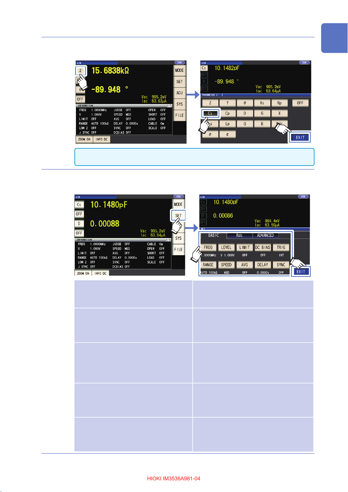
Set the rst parameter to Cs and the third parameter to D. (p. 41)
Example: Set the rst parameter to Cs
11
Measurement Process
8
22
When you wish to perform DC in addition to AC measurement, set the parameter to Rdc.: “To
perform DC measurement (DC resistance measurement)” (p. 42)
Set the measurement conditions.
Press the SET key, select the BASIC tab, and congure the settings as desired. (The numbers
underneath the buttons indicate the default settings.)
11
22
FREQ
RANGE
LEVEL
SPEED
LIMIT
Measurement frequency: 1.0000 kHz
(p. 47)
(Required: congure based on the
measurement sample.)
Measurement range: AUTO (p. 48)
(Required: congure based on the
measurement sample.)
Measurement signal mode:
Open circuit voltage (V) mode
Measurement signal level: 1.000 V
(p. 52)
(Required: congure based on the
measurement sample.)
Measurement speed: MED (p. 58)
(Optional: Change this setting when
you wish to perform measurement
more quickly or at a higher level of
precision.)
Voltage and current limit: OFF
(p. 62)
(Optional: Set to ON when you wish
to limit the voltage or current that is
applied to the sample.)
AVG
DC BIAS
DELAY
TRIG
SYNC
Average: OFF (p. 60)
(Optional: Set to ON when you wish to
prevent instability in the display value.)
DC bias: OFF (p. 63)
(Optional: Set to ON when you wish
to superimpose the DC voltage on
the measurement signal during
capacitance measurement.)
Trigger delay: 0.0000 s (p. 67)
(Optional: If the trigger synchronous
output function is enabled, set to a
large enough value that measurement
can stabilize.)
Trigger: INT (p. 66)
(Optional: Set to EXT when you wish
to input the trigger manually, using
EXT I/O, or using the interface.)
Trigger synchronous output function:
OFF (p. 68)
(Optional: Change the setting when
you wish to apply the signal to the
sample during measurement only.)
33
33
9
Page 15
Measurement Process
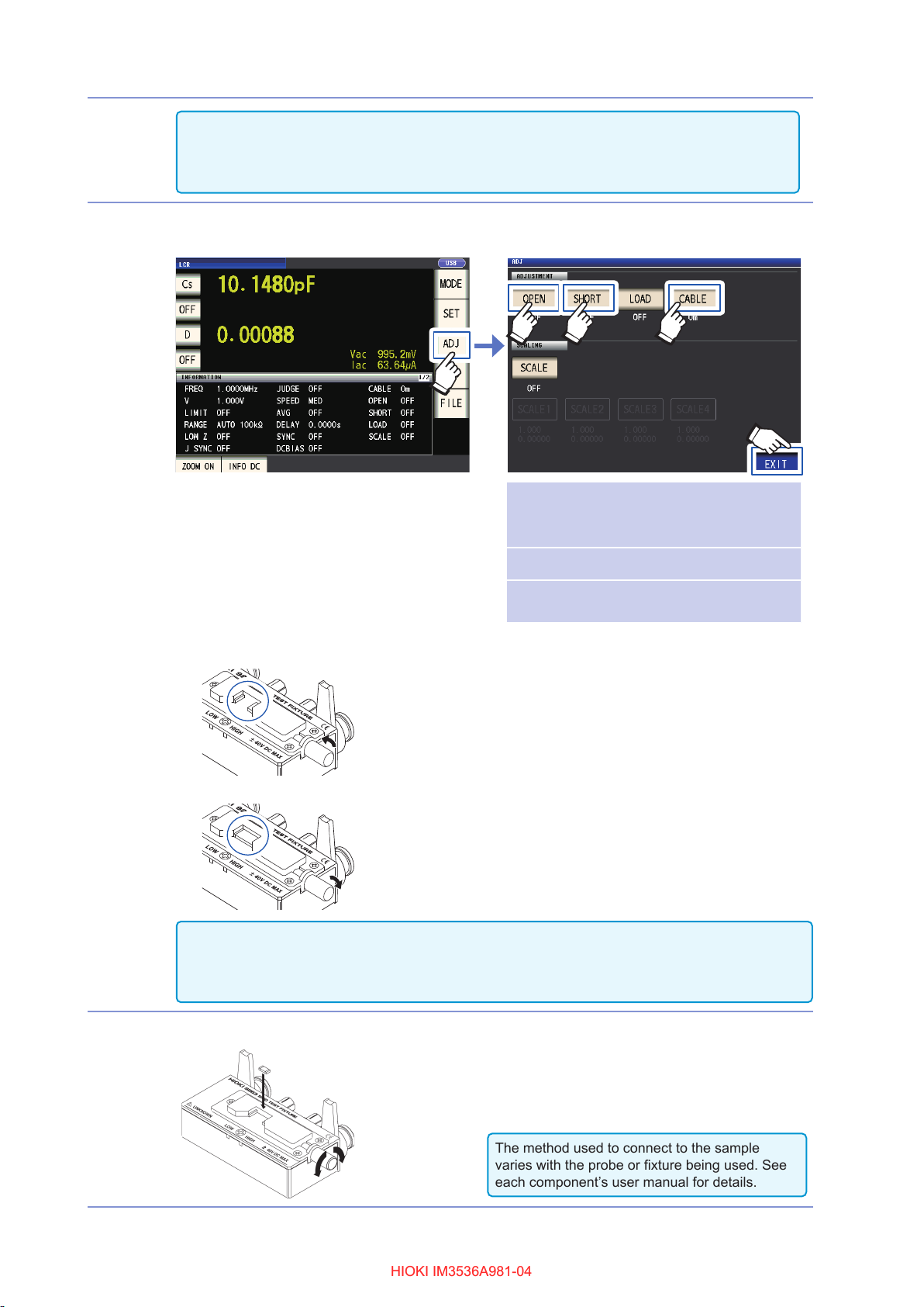
The method used to connect to the sample
varies with the probe or xture being used. See
each component’s user manual for details.
HIOKI IM3536A981-04HIOKI IM3536A981-04
• To save measurement conditions internally or load previously saved measurement conditions:
“6 Saving and Loading Measurement Condition and Correction Value Data” (p. 131)
• To perform DC (DC resistance) measurement: “3.4 Setting Measurement Conditions (Basic
Settings)” (p. 46)
Wait at least 60 minutes after turning on the instrument and then perform correction.
9
1. Press the ADJ key.
2233 44
11
55
CABLE
OPEN
SHORT
2. Set the cable length (for the 9263, use a setting of 0 m).
3. Place the 9263 SMD Test Fixture in the open state and perform open correction.
4. Place the 9263 SMD Test Fixture in the shorted state and perform short correction.
• To save measurement conditions internally or load previously saved measurement conditions: “6
Saving and Loading Measurement Condition and Correction Value Data” (p. 131)
• The open state and shorted state vary with the probe or xture being used. (p. 3)
For more information, see each component’s user manual.
“5.1 Setting the Cable Length
(Cable Length Correction)”
(p. 104)
“5.2 Open Correction” (p. 105)
“5.3 Short Correction” (p. 112)
Connect the test sample to the 9263 SMD test xture.
10
10
Page 16
11
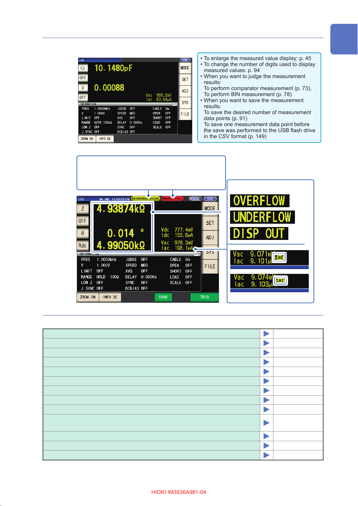
• To enlarge the measured value display: p. 45
• To change the number of digits used to display
measured values: p. 94
• When you want to judge the measurement
results:
To perform comparator measurement (p. 73),
To perform BIN measurement (p. 78)
• When you want to save the measurement
results:
To save the desired number of measurement
data points (p. 91)
To save one measurement data point before
the save was performed to the USB ash drive
in the CSV format (p. 149)
HIOKI IM3536A981-04HIOKI IM3536A981-04
Check the measurement results. (p. 44)
Measurement Process
An error message or error display will be shown:
Error massage
Reference Value: No measured value accuracy guarantee
Memory Full: Memory full
Hi Z: Hi Z reject error
Error display
See “11.3 Error Massage and Error Display” (p. 238).
The following functionality is also available
Measuring conductivity and permittivity
Measuring at a high level of precision
Limiting instability of display values
Setting measurement conditions for each measurement range
Increasing the measurement precision or measurement speed
Detecting contact errors during two-terminal measurement
Detecting poor contact with the sample during four-terminal measurement
Changing the key tone or judgment tone
Disabling key operation (key lock function)
Performing measurement by outputting a signal from an external device
to the instrument
Controlling the instrument by sending commands from a computer
Saving settings data to the USB ash drive
Loading settings data from the USB ash drive
p. 71
p. 59
p. 60
p. 83
p. 86
p. 88
p. 89
p. 96
p. 97
p. 66, p. 169
p. 140
p. 161
p. 163
11
Page 17

Safety Information
HIOKI IM3536A981-04HIOKI IM3536A981-04
Safety Information
This instrument is designed to conform to IEC 61010 Safety Standards, and has been thoroughly
tested for safety prior to shipment. However, using the instrument in a way not described in this
manual may negate the provided safety features.
Before using the instrument, be certain to carefully read the following safety notes.
DANGER
Mishandling during use could result in injury or death, as well as damage to the
instrument. Be certain that you understand the instructions and precautions in
the manual before use.
WARNING
With regard to the electricity supply, there are risks of electric shock, heat
generation, re, and arc discharge due to short circuits. If persons unfamiliar
with electricity measuring instrument are to use the instrument, another person
familiar with such instruments must supervise operations.
Notation
In this manual, the risk seriousness and the hazard levels are classied as follows.
DANGER
WARNING
CAUTION
IMPORTANT
*
Indicates an imminently hazardous situation that will result in death or serious
injury to the operator.
Indicates a potentially hazardous situation that may result in death or serious
injury to the operator.
Indicates a potentially hazardous situation that may result in minor or moderate
injury to the operator or damage to the instrument or malfunction.
Indicates information related to the operation of the instrument or maintenance
tasks with which the operators must be fully familiar.
Indicates a high voltage hazard.
If a particular safety check is not performed or the instrument is mishandled,
this may give rise to a hazardous situation; the operator may receive an electric
shock, may get burnt or may even be fatally injured.
Indicates the prohibited action.
Indicates the action which must be performed.
Additional information is presented below.
12
Bold
Windows
Names and keys on the screen are indicated in boldface.
Unless otherwise specied, “Windows” represent Windows 7, Windows 8 and
Windows 10.
Page 18
Safety Information
HIOKI IM3536A981-04HIOKI IM3536A981-04
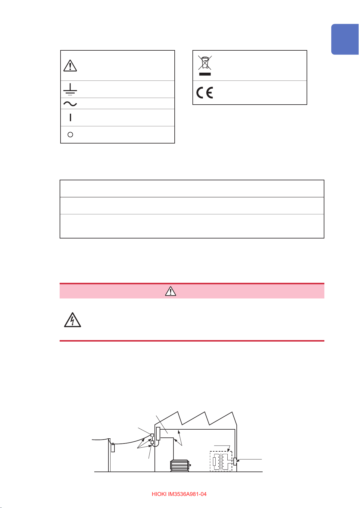
Symbols on the instrument
Indicates cautions and hazards.
When the symbol is printed on the
instrument, refer to a corresponding
topic in the Instruction Manual.
Indicates a grounding terminal.
Indicates AC (Alternating Current).
Indicates the ON side of the power
switch.
Indicates the OFF side of the power
switch.
Symbols for Various Standards
Indicates the Waste Electrical and
Electronic Equipment Directive
(WEEE Directive) in EU member
states.
Indicates that the product conforms
to regulations set out by the EU
Directive.
Accuracy
We dene measurement tolerances in terms of f.s. (full scale), rdg. (reading) and dgt. (digit) values,
with the following meanings:
f.s.
rdg.
(maximum display value)
The maximum displayable value. This is usually the name of the currently selected range.
(reading or displayed value)
The value currently being measured and indicated on the measuring instrument.
(resolution)
dgt.
The smallest displayable unit on a digital measuring instrument, i.e., the input value that
causes the digital display to show a “1” as the least-signicant digit.
Measurement categories
To ensure safe operation of measuring instruments, IEC 61010 establishes safety standards
for various electrical environments, categorized as CAT II to CAT IV, and called measurement
categories.
DANGER
• Using a measuring instrument in an environment designated with a higher-
numbered category than that for which the instrument is rated could result in a
severe accident, and must be carefully avoided.
• Never use a measuring product that lacks category labeling in a CAT II to CAT
IV measurement environment. Doing so could result in a serious accident.
CAT II: When directly measuring the electrical outlet receptacles of the primary electrical
circuits in equipment connected to an AC electrical outlet by a power cord (portable
tools, household appliances, etc.)
CAT III:
CAT IV: When measuring the circuit from the service drop to the service entrance, and to the
When measuring the primary electrical circuits of heavy equipment (xed installations)
connected directly to the distribution panel, and feeders from the distribution panel to outlets
power meter and primary overcurrent protection device (distribution panel)
Distribution panel
Service entrance
Service drop
CAT IV
Power meter
Internal wiring
CAT III
Fixed Installation
CAT II
T
Outlet
13
Page 19
Operating Precautions
HIOKI IM3536A981-04HIOKI IM3536A981-04
Operating Precautions
Follow these precautions to ensure safe operation and to obtain the full benets of the various functions.
Use of the instrument should conform not only to its specications, but also to the specications of all
accessories, options, and other equipment in use.
DANGER
If the probes, cords or the instrument is damaged, there is a risk of electric
shock. Before using the instrument, perform the following inspection.
• Before using the instrument, check that the coating of the probes or cords
are neither ripped nor torn and that no metal parts are exposed. Using the
instrument under such conditions could result in electric shock. Replace the
probes or cords with those specied by our company.
• Verify that the instrument operates normally to ensure that no damage occurred
during storage or shipping. If you nd any damage, contact your authorized
Hioki distributor or reseller.
Installing the instrument
Installation environment
Installing the instrument in inappropriate locations may cause a malfunction of
instrument or may give rise to an accident. Avoid the following locations.
• Exposed to direct sunlight or high temperature
• Exposed to corrosive or combustible gases
• Exposed to a strong electromagnetic eld or electrostatic charge
• Near induction heating systems (such as high-frequency induction heating
systems and IH cooking equipment)
• Susceptible to vibration
• Exposed to water, oil, chemicals, or solvents
• Exposed to high humidity or condensation
• Exposed to high quantities of dust particles
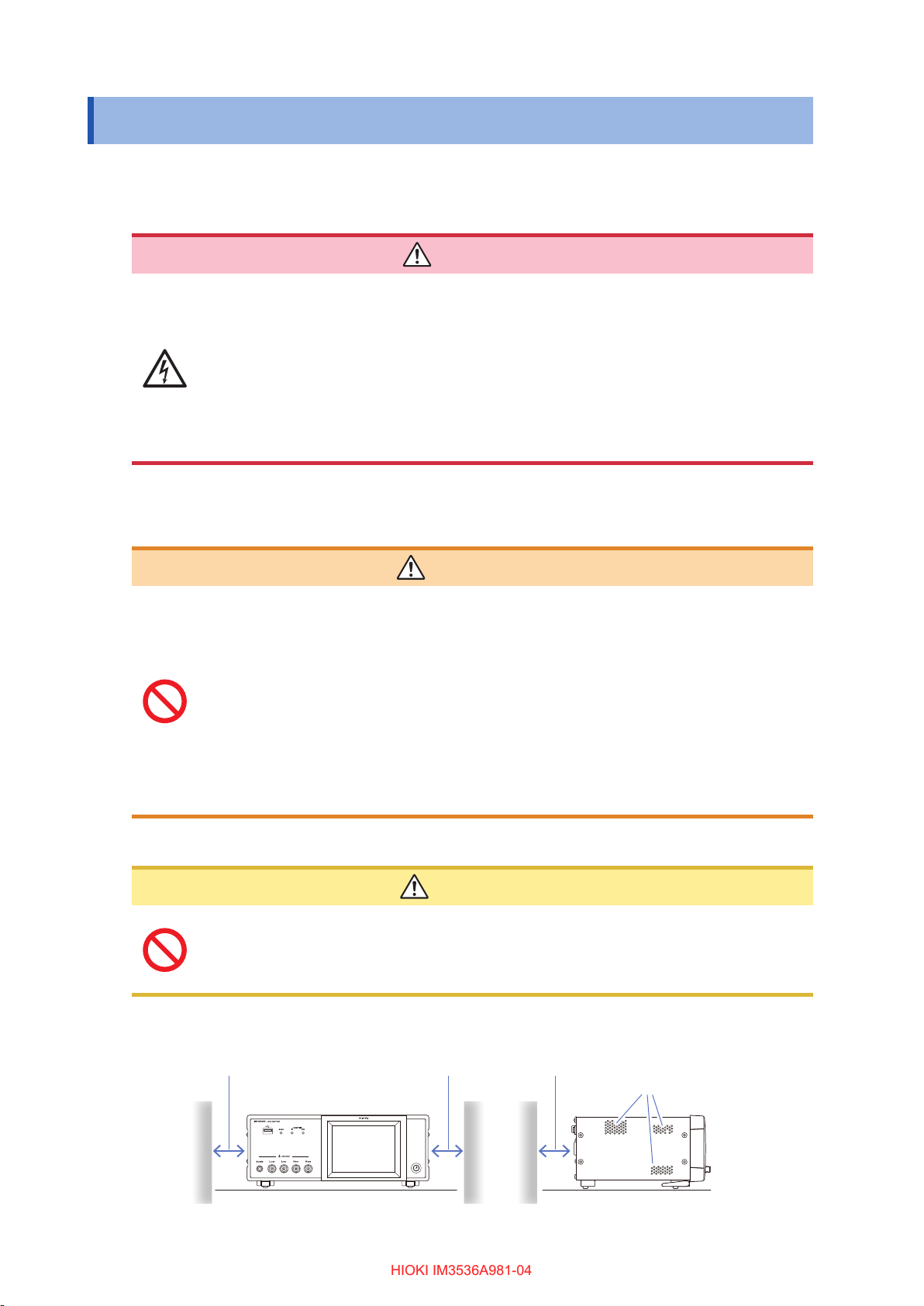
Installation instructions
• Do not place the device on an unstable table or an inclined place. Dropping or knocking down the device can cause injury or damage to the device.
• Leave sufcient space around the instrument when positioning it. Failure to do so may
result in damage to the instrument or re.
WARNING
CAUTION
14
• Install with the bottom surface facing downward.
• Vents must not be obstructed.
50 mm or more 50 mm or more 10 mm or more
Vents
Back
Page 20
Operating Precautions
HIOKI IM3536A981-04HIOKI IM3536A981-04
The instrument can be used with the stand (p. 20).
It can also be rack-mounted (p. Appx.12).
Shipping precautions
Hioki disclaims responsibility for any direct or indirect damages that may occur when this instrument
has been combined with other devices by a systems integrator prior to sale, or when it is resold.
Handling the instrument
This instrument complies with EN 61326 Class A. This instrument may cause interference if
used in residential areas. Such use must be avoided unless the user takes special measures to
reduce electromagnetic emissions to prevent interference to the reception of radio and television
broadcasts.
DANGER
To avoid electric shock, do not remove the instrument’s case. The internal
components of the instrument carry high voltages and may become very hot
during operation.
• Note that the instrument may be damaged if the applied voltage or current exceeds
the measurement range.
• Do not use excessive force on the touch panel, and do not use sharp objects that
could damage the touch screen.
• Do not apply heavy downward pressure with the stand extended. The stand could be
damaged.
• If the instrument exhibits abnormal operation or display during use, review the information in “11.2 Troubleshooting” (p. 231) and “11.3 Error Massage and Error Display” (p. 238) before contacting your dealer or Hioki representative.
• To avoid damage to the instrument, protect it from physical shock when transporting
and handling. Be especially careful to avoid physical shock from dropping.
• After use, always turn off the instrument.
Before turning on the instrument
• Before turning the instrument on, make sure the supply voltage matches that
indicated on its power connector. Connection to an improper supply voltage
may damage the instrument and present an electrical hazard.
• To avoid electrical accidents and to maintain the safety specications of this
instrument, connect the power cord provided only to a 3-contact (two-conductor
+ ground) outlet.
• Be sure to ground the power cord. Failure to do so will cause the enclosure to
have a voltage equal to half the supply voltage, resulting in electric shock.
• To avoid shock and short circuits, turn off all power before connecting probes
or cords.
CAUTION
WARNING
CAUTION
Do not connect the supply voltage improperly. Doing so may destroy the instrument’s
internal circuitry.
15
Page 21
Operating Precautions
HIOKI IM3536A981-04HIOKI IM3536A981-04
DC resistance measurement only
To suppress noise, the instrument needs to be set to match the frequency of the power source. Before
operating, set the instrument to the frequency of your commercial power. If the supply frequency is not set
properly, measurements will be unstable.
See “Line frequency (DC)” (p. 57).
Handling the cords, xtures, and probes
If the insulation on a cord melts, the metal conductor may be exposed. Do not
use any cord whose metal conductor is exposed. Doing so could result in electric
shock, burns, or other hazard.
• To avoid breaking the cords or probes, do not bend or pull them.
• Avoid stepping on or pinching cords, which could damage the cord insulation.
• Keep in mind that, in some cases, conductors to be measured may be hot.
• To avoid damage to the instrument, do not short-circuit the measurement terminals
and do not input voltage to the measurement terminals.
WARNING
CAUTION
• For safety reasons, disconnect the power cord when the instrument is not used.
• To avoid damaging the power cord, grasp the plug, not the cord, when unplugging it
from the power outlet.
• To prevent damage to the BNC connector or junction, be sure to release the locking
mechanism, grip the head of the connector (not the cord), and pull it out.
• Put the protective cap back on the connector when not in use. If the protective cap is
not properly inserted, dust or other foreign matter may enter the connector and cause
damage.
IMPORTANT
• Use only the specied connection cords. Using a non-specied cable may result in incorrect
measurements due to poor connection or other reasons.
Before using a xture or the like, read the instruction manual supplied with the product to be used.
Before using the USB ash drive
CAUTION
• Do not transport the instrument while a USB ash drive is connected. Damage could
result.
• Inserting a USB ash drive upside down, backwards or in the wrong direction may
damage the USB ash drive and/or the instrument.
16
• Some USB ash drives are susceptible to static electricity. Exercise care when using
such products because static electricity could damage the USB ash drive or cause
malfunction of the instrument.
Page 22
Operating Precautions
HIOKI IM3536A981-04HIOKI IM3536A981-04
IMPORTANT
• USB ash drives have a limited usable lifetime. After long-term use, data reading and writing
will fail, at which time the USB ash drives must be replaced.
• When a USB ash drive is accessed, the color of the USB icon changes from blue to red. Do
not turn off the instrument while the USB ash drive is being accessed. Also, never remove the
USB ash drive from the instrument. Doing so may result in the data in the USB ash drive be-
ing lost.
• Hioki cannot recover data from damaged or faulty storage media resulting from abnormalities.
We are also unable to provide compensation for such data loss,regardless of the contents or
cause of the failure or damage. We recommend making a backup of all important data on a
computer or other storage devices..
With some USB ash drives, the instrument may not start up if it is turned on while the USB ash
drive is inserted. In such a case, turn the instrument on rst, and then insert the USB ash drive.
It is recommended to try out operation with a USB ash drive before starting to use it for actual
measurements.
Before connecting external I/O
WARNING
• The ISO_5V pin of the EXT I/O connector is a 5 V power output. Do not apply
external power to this pin.
To avoid electric shock or damage to the equipment, always observe the following
precautions when connecting to EXT I/O connectors.
• Always turn off the power to the instrument and to any devices to be connected
before making connections.
• Be careful to avoid exceeding the ratings of EXT I/O connectors. (p. 186)
• During operation, a wire becoming dislocated and contacting another
conductive object can be serious hazard. Use screws to secure the external
connectors.
• Ensure that devices and systems to be connected to the EXT I/O terminals are
properly isolated.
CAUTION
To avoid damage to the instrument, observe the following cautions:
• Do not apply voltage or current to the EXT I/O terminals that exceeds their ratings.
• Do not short the ISO_5V and ISO_COM EXT I/O connectors.
See “Instrument connector signal assignments” (p. 170).
Handling the LCR application disc
• When driving relays, be sure to install diodes to absorb counter-electromotive force.
• Exercise care to keep the recorded side of discs free of dirt and scratches. When writing text on a
disc’s label, use a pen or marker with a soft tip.
• Keep discs inside a protective case and do not expose to direct sunlight, high temperature, or
high humidity.
• Hioki is not liable for any issues your computer system experiences in the course of using this
disc.
17
Page 23

Operating Precautions
HIOKI IM3536A981-04HIOKI IM3536A981-04
18
Page 24
1
HIOKI IM3536A981-04HIOKI IM3536A981-04
Overview
1.1 Product Overview and Features
The HIOKI IM3536 LCR Meter is an impedance measuring instrument which achieves high speed
and high accuracy.
It can be used in a wide range of applications thanks to its broad range of measurement
frequencies and its ability to set measurement conditions based on measurement signal levels.
Overview
Wide range of measurement
conditions
Measurement frequencies: 4 Hz to 8 MHz
Measurement signal levels: 10 mV to 5 V
Continuous measurement mode
Allows measurements to be performed
continuously using precongured
measurement conditions. This function
enables, for example, making pass/fail
judgment with different measurement
conditions.
(Example: Performing C-D measurement with
120 Hz and Rs measurement with 100 kHz in
succession)
Comparator function (p. 73)
Makes HI/IN/LO judgments based on
measured values and two precongured
parameters.
Capable of high-speed
measurement
Up to 1 ms (typical values)
Various interfaces supported
Supports the most suitable EXT I/O (handler
interface) for production lines, USB, GP-IB,
RS-232C and LAN.
BIN function (p. 78)
Ranks measured values in up to 10 categories
based on 2 precongured parameters.
Low impedance can be measured
with high degree of accuracy
Allows you to congure the instrument to
measure low impedance values at a high level
of precision. (p. 59)
19
Page 25

Names and Functions of Parts
HIOKI IM3536A981-04HIOKI IM3536A981-04
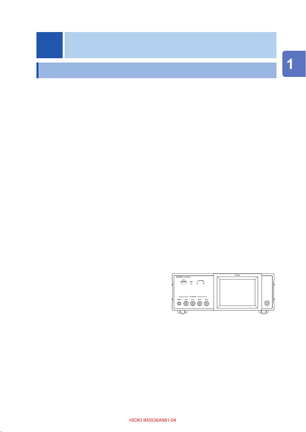
1.2 Names and Functions of Parts
Front
Measurement LEDs
Lights during measurement.
Front USB connector
Connect a USB ash drive
storage device (p. 146).
Judgment result
indication LEDs
Indicates the judgment results
for comparator and BIN
measurement (p. 73, p. 78).
See
“Handling the cords,
xtures, and probes”
(p. 16).
Measurement terminals
Connect measurement cables or a
xture(p. 37).
H
jack: Current source terminal
CUR
H
jack: Detected voltage high terminal
POT
L
jack: Detected voltage low terminal
POT
L
jack: Measurement current detected
CUR
GUARD jack: Shield (measurement ground)
terminal
terminal
LCD display
This is a touch panel display.
Press the keys displayed on the
screen to operate the instrument.
Power button
Turns the instrument on and off
while the main power
in the “on” position
(The main power switch is
located at the rear.)
switch is
(p. 38)
.
Left side Right side
Vents
Keep clear of obstructions(p. 14).
Stand
Enables the instrument to be tilted.
CAUTION
Do not apply heavy downward pressure with the stand extended. The stand could be
damaged.
20
Page 26
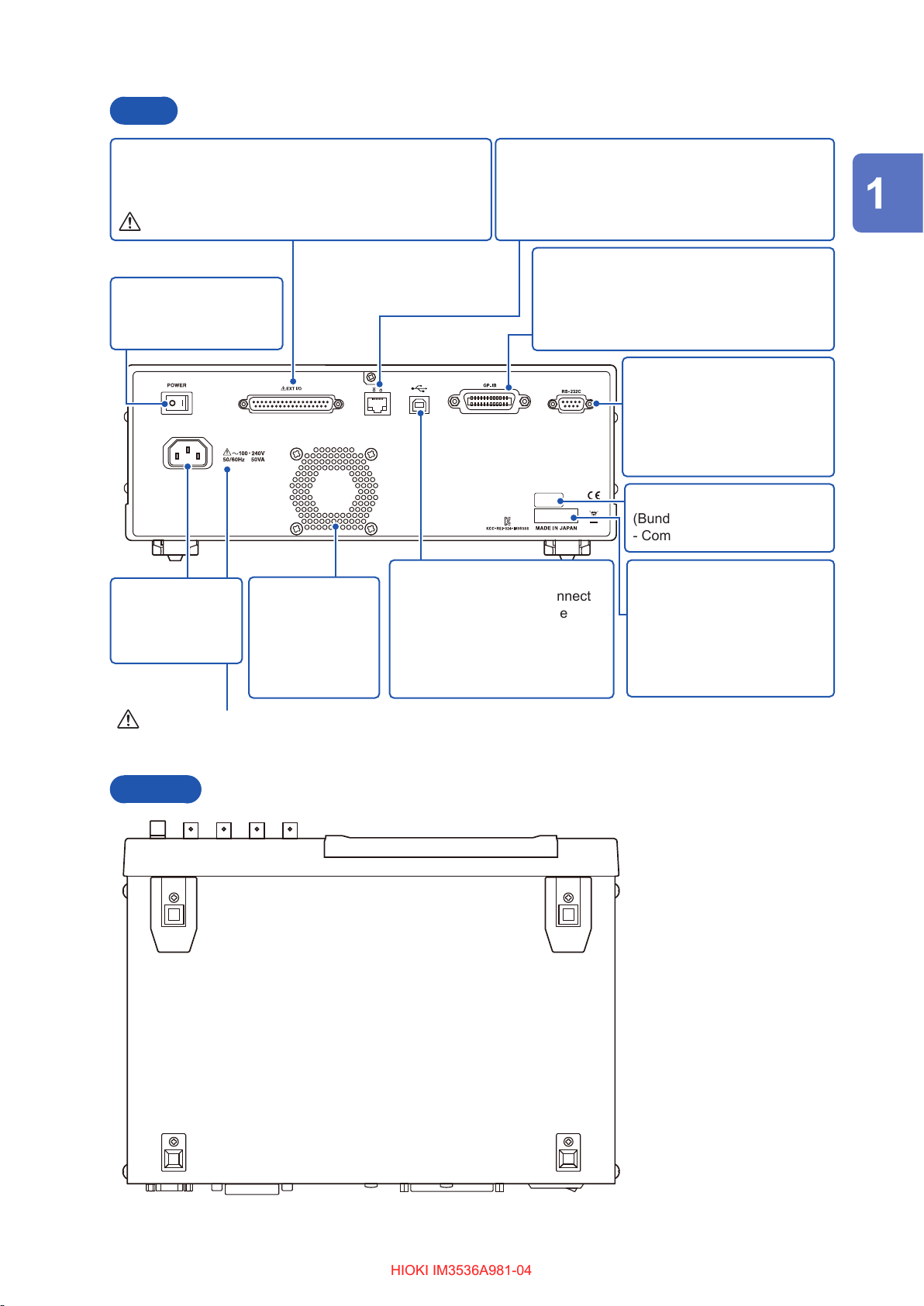
Rear
HIOKI IM3536A981-04HIOKI IM3536A981-04
Names and Functions of Parts
EXT I/O connector
Allows you to control the start of measurement and capture
judgment results by connecting a PLC or I/O board.(p. 170)
See “Before connecting external I/O” (p. 17).
Main power switch
Turns the power on and
off (p. 38).
Rear USB connector
Power inlet
Connect the
supplied power
cord (p. 36).
Vent
Keep clear of
obstructions.
Keep foreign
objects and other
material away.
Connect a USB cable. Connect
to a computer to control the
instrument with communication
commands.
(Bundled LCR Application Disc Communications Manual)
LAN connector
Allows you to connect the instrument to external
devices using a LAN cable.
(Bundled LCR Application Disc - Communications
Manual)
GP-IB connector
Allows you to connect the instrument to
external devices using a GP-IB cable.
(Bundled LCR Application Disc Communications Manual)
RS-232C connector
Allows you to connect the
instrument to external devices
using a RS-232C cable.
(Bundled LCR Application Disc
- Communications Manual)
MAC address of the LAN
(Bundled LCR Application Disc
- Communications Manual)
Serial number
The rst four digits of the 9-digit
number indicate the year (its
last two digits only) and the
month of manufacture.
Do not remove this sticker as
the number is important.
Overview
See “Before turning on the instrument” (p. 15), and
“Handling the cords, xtures, and probes” (p. 16).
Bottom
This instrument can be rack
mounted.
See “Appx. 9 Attaching RackMounting Hardware to the
Instrument” (p. Appx.12).
21
Page 27

Screen Layout and Operation
HIOKI IM3536A981-04HIOKI IM3536A981-04
1.3 Screen Layout and Operation
This instrument allows you to use a touch panel to set and change all measurement conditions.
Gently touch a key on the screen to select the item or numerical value set for that key.
A selected key turns black.
This manual refers to the act of lightly placing your nger on the screen as “touching” it, and a
nger
mark is used on the screen to represent this action.
Do not use excessive force on the touch panel, and do not use sharp objects that could
damage the touch screen.
Screen transition diagram
Continuous measurement mode
Measurement screen
CAUTION
This screen is
used to select
the measurement
mode (p. 26).
MODE screen
This screen is used to view continuous
measurement results (p. 24).
Return to the Measurement screen with the
EXIT key.
This screen is
used to congure
continuous
measurement
(p. 27).
SET screen
This screen is
used to check and
manipulate les
on the USB ash
drive (p. 31).
FILE screen
22
Page 28

LCR mode
HIOKI IM3536A981-04HIOKI IM3536A981-04
Screen Layout and Operation
This screen is
used to select the
measurement mode
(p. 26).
Overview
Measurement screen
This screen is used to view measured
values and measurement condition
settings information. (p. 24,p. 28)
MODE screen
This screen is used
to congure detailed
settings such as
measurement
conditions (p. 27).
SET screen
This screen is
used to congure
correction
functionality
(p. 29).
ADJ screen
This screen is
used to congure
the instrument’s
interfaces, to set the
time and date, and
to check the system
(p. 30).
Return to the Measurement screen with the
EXIT key.
SYS screen
This screen is
used to check and
manipulate les on
the USB ash drive
(p. 31).
FILE screen
23
Page 29
Screen Layout and Operation
HIOKI IM3536A981-04HIOKI IM3536A981-04
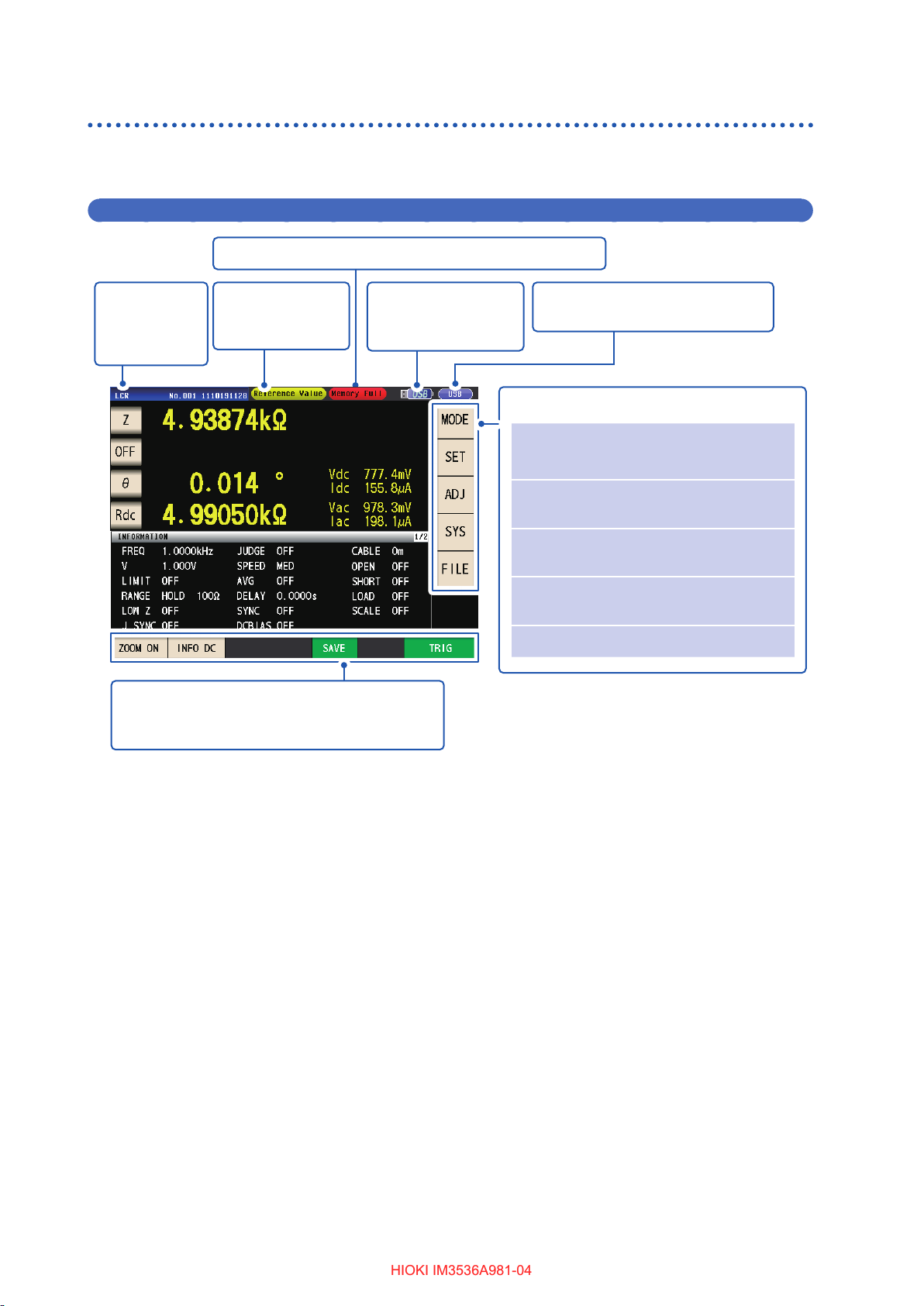
Viewing measured values (Measurement screen)
This is the rst screen displayed when the instrument is turned on.
Touch the EXIT key to return to the measurement screen from another screen.
Displaying elements used in both LCR mode and continuous measurement mode
Indicates the usage status of internal memory (p. 93).
Indicates
the selected
measurement
mode.
Operation keys
Displays operation keys as appropriate for the
measurement mode and instrument state.
Displays error
messages.
(p. 238)
Indicates that a
USB ash drive is
connected (p. 146).
Indicates the interface that is
currently set (p. 140).
Menu keys
MODE
SET Set the advanced settings
ADJ Set the correction (p. 29).
SYS Set the system (p. 30).
FILE Set the save settings (p. 31).
Select the measurement mode
p. 26).
(
(p. 27).
(LCR mode only)
(LCR mode only)
24
Page 30
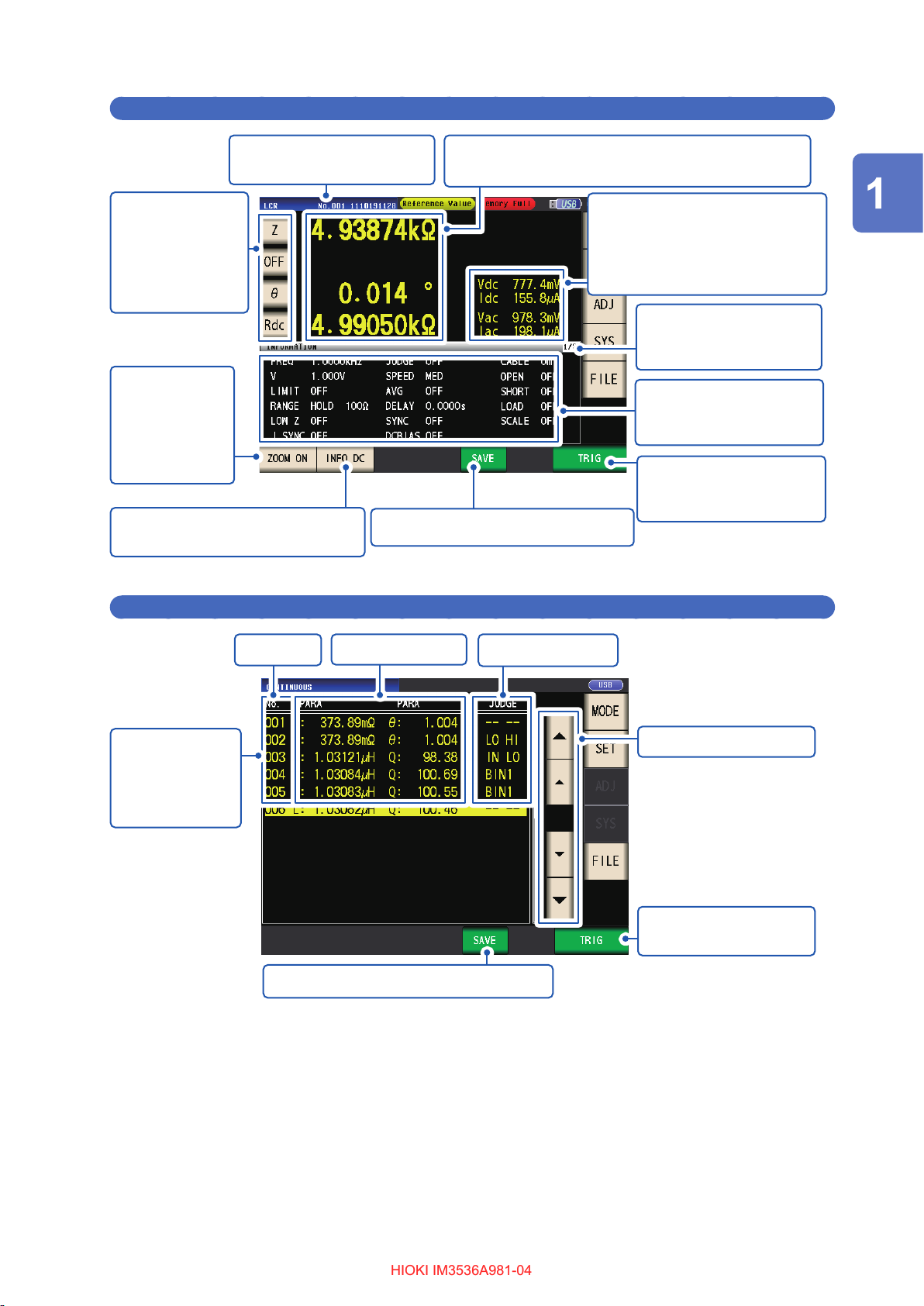
Measurement screen in LCR mode
HIOKI IM3536A981-04HIOKI IM3536A981-04
Screen Layout and Operation
Indicates the name of the
loaded panel (p. 136).
Parameter keys
Sets which
parameters to
display on the
measurement
screen (p. 41).
Enlarges the
display of
measured values
and comparator
judgment results.
(p. 45)
Switches measurement condition
settings information (p. 28).
Measured values*
Displays measured values for various parameters.
Monitor values
Vac, Vdc: Voltage between the
sample terminals
Iac, Idc: Current passing through
the sample
Displays measurement
condition settings
information.
Displays measurement
condition settings
information. (p. 28)
When the external trigger is
selected, activates the trigger
manually.(p. 67)
Saves the measurement data (p. 151).
*How to view measured values: See “3.2 Viewing Measured Values” (p. 44).
Overview
Measurement screen in continuous measurement mode
Panel No. Measured value
Displays a list of
the panels being
used to perform
continuous
measurement.
Saves the measurement data (p. 151).
*How to view measured value and judgment result: See “4.3 Checking Continuous Measurement Results” (p. 100).
*
Judgment result
*
Scrolls the screen.
Starts continuous
measurement (p. 100).
25
Page 31

Screen Layout and Operation
HIOKI IM3536A981-04HIOKI IM3536A981-04
Select the measurement mode (MODE screen)
This screen is used to select the measurement mode.
Touch the MODE key.
1
After changing the measurement mode, check all settings (including correction) before performing
measurement.
(Correction values will be deleted, so you will need to repeat the correction process.)
Select the measurement mode.
2
Displays the measurement screen for
the selected mode.
LCR LCR mode (p. 41)
CONTINUOUS Continuous measurement
mode (p. 99)
26
Page 32

Screen Layout and Operation
HIOKI IM3536A981-04HIOKI IM3536A981-04
Setting detailed settings such as measurement conditions (SET screen)
This screen is for conguring the measurement conditions you want to change and other advanced
settings.
Select the measurement mode (p. 26) before conguring the advanced settings.
(Example screen: LCR mode)
For more information about the continuous measurement (CONTINUOUS) mode screen, see “4 Using
Continuous Measurement Mode” (p. 99)
Touch the SET key.
1
Touch a tab.
2
Touch the key for the parameter you
3
wish to set.
The settings screen for the parameter will
be displayed.
Congure settings for LCR mode and
4
continuous measurement mode.
See “3 Performing Measurements in
LCR Mode” (p. 41), and “4 Using
Continuous Measurement Mode” (p. 99).
Overview
BASIC Basic setting
Rdc DC resistance measurement
setting (shown during LCR
mode operation only)
ADVANCED Application settings
27
Page 33

Screen Layout and Operation
HIOKI IM3536A981-04HIOKI IM3536A981-04
Checking measurement condition settings information
You can check settings information on the
Measurement screen during LCR mode operation.
Current measurement conditions
(This information is not shown when using the zoom
display (p. 45)).
INFO AC
Information related to AC measurement is displayed.
INFO DC
Information related to DC measurement is displayed.
INFO COMP
(When comparator function has been set)
Displays information about comparator measurement
judgment standards.
Touching the INFO key switches the
displayed information.
(The INFO key display will vary depending
on what type of information is being
displayed.)
INFO BIN
(When BIN function has been set)
Displays information about BIN measurement judgment
standards.
28
Touch again to display information for BIN 6 to BIN 10.
(When display information is for BIN 6 to BIN 10, this
key is INFO AC key.)
Page 34

Screen Layout and Operation
HIOKI IM3536A981-04HIOKI IM3536A981-04
The following information can be displayed:
Display Description Remarks
FREQ Measurement frequency
RANGE Measurement range
LOW Z Low Z high accuracy mode
J SYNC
SPEED Measurement speed
AVG Average
V Measurement signal level
DELAY Trigger delay
SYNC Trigger synchronous output
JUDGE Measurement result judgment
OPEN Open correction
SHORT Short correction
LOAD Load correction
CABLE Cable correction
SCALE Scale correction (Correlation Correction)
LIMIT Limit
DC BIAS DC bias
L FREQ Line frequency
DCR OFFSET DC adjustment value acquisition time
DC DELAY
ADJ DELAY
*1: When set to ON, the display will show ON* if set to a measurement range or measurement frequency for
which the output resistance will be 100
*2: The acquisition time will not be displayed if DC adjustment is ON. When DC adjustment is OFF, the display
will show RESERVED after DC offset acquisition, and the acquisition time will be displayed once acquisition
is complete.
JUDGE synchronization setting for the
measurement range
DC delay
Adjustment delay
*1
For AC and DC
AC: Setting
DC: Fixed to 1.00 V
Used for both AC and DC.
(Displayed for INFO AC only)
AC only
*2
DC only
.(See “Low Z High Accuracy Mode” (p. 59))
Ω
Overview
Conguring correction functionality (ADJ screen)
This screen is used to congure correction functionality (LCR mode only).
Touch the ADJ key.
1
Touch the key for the parameter you
2
wish to set.
The settings screen for the parameter will
be displayed.
Congure the settings.
3
See “5 Error Correction” (p. 103).
29
Page 35

Screen Layout and Operation
HIOKI IM3536A981-04HIOKI IM3536A981-04
Conguring the instrument’s interfaces, setting the time and date, and
checking the system (SYS screen)
This screen is used to congure the instrument’s interfaces, to set the time and date, and to check
the system. (LCR mode only)
Touch the SYS key.
1
Touch a tab.
2
Touch the key for the parameter you
3
wish to set.
The settings screen for the parameter will
be displayed.
Check the settings and version number
4
or perform a test measurement.
See “7 Setting the System” (p. 139).
I/F Congure interface settings
INFO Check the version and other system
information
TEST Check the system
CLOCK Set the time
30
Page 36

Screen Layout and Operation
HIOKI IM3536A981-04HIOKI IM3536A981-04
Displaying and manipulating les on the USB ash drive (FILE screen)
This screen is used to display les saved on the USB ash drive and to congure and edit lerelated settings. It is displayed after the USB ash drive is inserted into the instrument’s receptacle.
Touch the FILE key.
1
Touch a tab.
2
LIST • Display les
• Load, save, or delete (initialize) les
SET Congure le-saving operation
Congure le-saving settings, display
3
les, and manipulate les.
See “8 Using USB Flash Drive
(Saving and Loading Data)” (p. 145).
Overview
31
Page 37

Screen Layout and Operation
HIOKI IM3536A981-04HIOKI IM3536A981-04
32
Page 38

2
HIOKI IM3536A981-04HIOKI IM3536A981-04
Measurement Preparations
2.1 Preparation Flowchart
Before preparing for measurement, be sure to read “Operating Precautions” (p. 14).
Refer to “Appx. 9 Attaching Rack-Mounting Hardware to the Instrument” (p. Appx.12) for rack
mounting.
(1) Installing the instrument (p. 14)
(2) Connecting the power cord (p. 36)
(3) Connecting the measurement cables, optional Hioki probes, or test xture to the
measurement connectors (p. 37)
Check that the instrument’s power switch is set to
the off position.
(4) Connecting the external interface (as needed)
Measurement Preparations
For more information about making RS-232C, GP-IB, USB, and LAN connections, see the
Communications Instruction Manual on the bundled LCR Application Disc.
RS-232C
GP-IB
USB
LAN
(5) Turning on the instrument (p. 38)
External interface
33
Page 39

Preparation Flowchart
HIOKI IM3536A981-04HIOKI IM3536A981-04
(6) Making instrument settings
• First, set the time and date (p. 40).
• When measuring DC resistance, be sure to set the line frequency before performing measurement
(p. 57).
After allowing the instrument to warm up for at least 60 minutes, perform open correction and short
correction and connect the instrument to the sample (p. 38).
34
Page 40

Pre-operation Inspection
The power cord insulation is not
torn, or any metal is not exposed.
HIOKI IM3536A981-04HIOKI IM3536A981-04
2.2 Pre-operation Inspection
Please read the “Operating Precautions” (p. 14) before use.
Before using the instrument, verify that it operates normally to ensure that no damage occurred
during storage or shipping. If you nd any damage, contact your authorized Hioki distributor or
reseller.
Peripheral device inspection
1
Do not use the instrument if damage is found,
as electric shock or shortcircuit accidents could
result. Contact your authorized Hioki distributor
or reseller.
No metal exposed
Metal
exposed
Measurement Preparations
The insulation on a cables is not
torn, or any metal is not exposed.
No metal exposed
Instrument inspection
2
The instrument is not damaged.
Not damaged
When the instrument is turned on
The splash screen (model no.,
version no.) is displayed.
Metal
exposed
Damaged
Not
displayed
If there is any damage, measured values may
be unstable and measurement errors may occur.
Replace the cable with an undamaged one.
If damage is evident, request repairs.
The power cord may be damaged, or the
instrument may be damaged internally.
Request repairs.
“11.2 Troubleshooting” (p. 231)
Displayed
No error is displayed on the
splash screen.
No error displayed
Inspection complete
An error
indication
occurs
(Err)
The instrument may be damaged internally.
Request repairs.
See “Transporting the instrument” (p. 230).
35
Page 41

Connecting the Power Cord
HIOKI IM3536A981-04HIOKI IM3536A981-04
2.3 Connecting the Power Cord
Be sure to read the “Before turning on the instrument” (p. 15), and “Handling the cords, xtures,
and probes” (p. 16) before connecting the power cord.
Connect the power cord to the power inlet on the instrument, and plug it into an outlet.
Check that the main power switch is set to the off position.
1
Connect a power cord that matches the line voltage to the power inlet on the
2
instrument. (100 V AC to 240 V AC)
Rear
3
Power inlet
Plug the other end of the power cord into an outlet.
36
Page 42

Connecting the Measurement Cables, Probes, or Fixture
HIOKI IM3536A981-04HIOKI IM3536A981-04
2.4 Connecting the Measurement Cables, Probes, or
Fixture
Be sure to read the “Handling the cords, xtures, and probes” (p. 16) before connecting
measurement cables, probes or test xture.
Connect your measurement cables, optional Hioki probes or test xture to the measurement
terminals. Refer to “Options (reference: open and short correction states)” (p. 3) for details. See
the instructions provided with the xture for operating details.
Example: Hioki optional test xture
Connect directly to the measurement jacks
with the label side up, and afx with the
levers on the left and right.
Example: Hioki optional Model 9140-10
Connect the red plugs to the H
CUR
jacks, and the black plugs to the L
jacks.
Black
Black
Red
and H
CUR
Red
POT
and L
Example: Hioki optional Model 9500-10
Connect the H
CUR
POT
CUR
, and L
POT
BNC
, H
, L
plugs to the corresponding terminals on the
instrument.
POT
Measurement Preparations
Points to pay attention to when making your own probe
• Use 50
• When it ships from the factory, the instrument has been adjusted for the length of its cable. Since use
of a cable with a different capacitance value between the coaxial cable’s core wire and the shielding will
introduce a measurement error, use a cable whose capacitance value is as close as possible to that used
when adjusting the instrument prior to its shipment (1 m: 111 pF/cable; 2 m: 215 pF/cable; 4 m: 424 pF/
cable).
• Make the portion of the core wire that is exposed as short as possible.
• Connect the H
(Ensure that a shield is not connected to a core wire.)
• In general, Hioki optional parts (p. 3) should be used for measurement cables and xtures. If you use a
probe yourself, it may not be able to satisfy the specications of this instrument.
• If all four terminals are disconnected, a meaningless number may be displayed on the unit.
coaxial cable for the measurement cable.
Ω
, L
, H
CUR
CUR
Measurement Terminal
Conguration
POT
, and L
shield pairs at the measurement sample side.
POT
Fixture
Normal mode
37
Page 43

Turning the Instrument On and Off
HIOKI IM3536A981-04HIOKI IM3536A981-04
2.5 Turning the Instrument On and Off
Before turning on the instrument, be sure to read “Before turning on the instrument” (p. 15).
Once you have connected measurement cables or an optional Hioki probe or test xture, set the
instrument’s main power switch to the on position. Once the main power switch has been set to the
on position, the instrument can be turned on and off using the power button on the front panel.
This feature is convenient when embedding the instrument in an automated tester or on a
production line. (If the main power switch is set to the off position in the suspended state, the
instrument will be turned on in the suspended state when the main power switch is next set to the
on position.)
Main power switch
Rear
Front
Power
button
38
Page 44

Turning the Instrument On and Off
What is the suspended state?
The instrument is turned off in the suspended
state. (Only the circuit needed to light up the
power button’s indicator will operate.)
HIOKI IM3536A981-04HIOKI IM3536A981-04
Turning on the instrument
Place the main power switch in the “on” (I).
The power button’s green indicator will light up.
Turning off the instrument
Place the main power switch in the “off” ( ).
The power button’s indicator will be turned off.
Placing the instrument in the suspended state
ON the main power in the state, hold
down the front Standby Key 2 seconds
approximately.
2 seconds
The power button’s red indicator will light up.
To cancel the suspended state
The instrument is in suspended state, press
the power button on the front.
Measurement Preparations
• When the power supply is interrupted by a power
failure or the like, the instrument recovers in the
measurement mode used before the power failure.
• Instrument settings will be retained (backed up)
even if the main power switch is set to the off
position.
Red indicator is lit up
The power button’s green indicator will light up.
To perform measurements at the level of accuracy indicated in the instrument’s specications,
allow it to warm up for at least 60 minutes after setting the main power switch to the on position or
canceling the suspended state.
39
Page 45

Setting the Date and Time
HIOKI IM3536A981-04HIOKI IM3536A981-04
2.6 Setting the Date and Time
Set the instrument’s date and time.
Data is recorded and managed based on the set date and time.
Press the SYS key.
1
Touch the CLOCK tab, and set the date
2
and time with the key.
(Year-Month-Day Hour-Minute-Second)
11
Press the SET key to accept the setting.
3
Press the EXIT key.
4
The measurement screen will be displayed.
22
Settable range :
00:00:00, January 1, 2000, to
23:59:59, December 31, 2099
40
Page 46

Performing Measurements in
HIOKI IM3536A981-04HIOKI IM3536A981-04
3
LCR Mode
The LCR mode allows you to measure the impedance, phase angle, and other items by applying
any frequency or level (effective value) signal to the element you want to measure. This function is
suitable for evaluating the passive element of a capacitor, coil, or the like.
First, set the measurement mode to LCR mode (p. 26).
3.1 Setting Display Parameters
You can select up to 4 of the 16 measurement parameters to display on the measurement screen.
These parameters are set on the measurement screen.
<Example> No. 1 parameter: Cs, No. 3 parameter: D (See “Parameters” (p. 42).)
Performing Measurements in LCR Mode
Touch the No. 1 parameter key.
1
Touch the Cs key and then the EXIT key
2
to accept the settings.
Touch the D key and then the EXIT key
4
to accept the setting.
11
Cs and D are set as the parameters.
22
3
11
22
Touch the No. 3 parameter key.
If OFF is selected in the parameter setting, a
measurement value is not displayed.
41
Page 47

Setting Display Parameters
HIOKI IM3536A981-04HIOKI IM3536A981-04
The following parameters are available:
Parameters Description Parameters Description
Z Impedance (
Y Admittance (S) Cp
θ
Rs
Rp
X Reactance (
G Conductance (S)
B Susceptance (S) OFF No display
Ls
Lp
Impedance phase angle (°)
Effective resistance= ESR (
(Equivalent series resistance)
Effective resistance (
(Equivalent parallel resistance)
Inductance (H)
(Equivalent series inductance)
Inductance (H)
(Equivalent parallel inductance)
Ω
Ω
Parameters
) Cs
*1
)
Ω
)
Ω
)
Q Q-factor
D Loss factor= tan
Rdc DC resistance (
σ
Capacitance (F)
(Equivalent series capacitance)
Capacitance (F)
(Equivalent parallel capacitance)
δ
)
Ω
Conductivity (See p. 71.)
ε
Permittivity (See p. 71.)
*2
*2
• Parameters other than Rdc are measured using an AC signal (AC measurement).
• Rdc measures DC resistance (DC measurement).
• For more information about series equivalent circuit mode and parallel equivalent circuit mode,
see p. Appx.10.
*1: The phase angle θ is shown based on the impedance Z.
*2: The following message will be displayed when you select either σ or ε as a parameter: “Please set the
area and length of DUT.” Touch the EXIT key to clear the message.
To perform DC measurement (DC resistance measurement)
When Rdc is set as a parameter, you can measure the DC resistance Rdc.
For more information about measurement condition settings, see “3.4 Setting Measurement
Conditions (Basic Settings)” (p. 46).
When Rdc is set as a parameter along with other parameters, DC resistance is measured (DC
measurement) after other parameters are measured using an AC signal (AC measurement).
DC measurement is performed automatically using the following series of operations:
Example: When the number of average iterations is 1
Change in settings
• Change from AC
measurement to
DC measurement
• Change in range
Adjustment
delay
(default value:
0.0030 sec.)
(See shaded
area below.)
Offset
11
Measurement
DC delay
(default
value: 0 sec.)
(See shaded
value below.)
DC resistance
22
measurement
Measurement
complete
(Measured
33
value output)
42
The DC resistance is measured after setting the generated voltage to 0 V, and the result
1
is used as the offset value. (See “DC adjustment (reducing measurement error) (DC)”
(p. 64).)
The DC resistance is measured after outputting 1.0 V.
2
The measurement error is reduced using the offset value, and the Rdc measured value
3
is output.
Page 48

Setting Display Parameters
HIOKI IM3536A981-04HIOKI IM3536A981-04
• When the sample is a capacitor, it may not be possible to perform DC resistance measurement normally.
• The time required until the DC signal level stabilizes differs depending on the test sample to be measured.
To facilitate more accurate measurement, observe the measurement waveform in advance and set
delay times (adjustment delay and DC delay) to allow the DC signal level to stabilize adequately. (See
“Measurement and data acquisition timing” (p. 69).)
Performing Measurements in LCR Mode
43
Page 49

Viewing Measured Values
HIOKI IM3536A981-04HIOKI IM3536A981-04
3.2 Viewing Measured Values
Measured values for each parameter are shown next to the corresponding parameter key. The
measured values shown in the screenshot below are as follows:
No. 1 parameter Z (impedance) : 4.93874 k
No. 2 parameter : No display
No. 3 parameter θ (Impedance phase angle) : 0.014°
No. 4 parameter Rdc (DC resistance) : 4.99050 k
Ω
Ω
Monitor values are displayed next to the measured values. The monitor values shown in the
screenshot below are as follows:
Vdc (Sample terminal voltage during DC measurement) : 777.4 mV
Idc (Current owing to sample during DC measurement) : 155.8 µA
Vac (Sample terminal voltage during AC measurement) : 978.3 mV
Iac (Current owing to sample during AC measurement) : 198.1 µA
For more detailed information about the screen layout, see “Viewing measured values (Measurement
screen)” (p. 24).
Measured value
Displays measured values for
each parameter.
Parameter
keys
Error message display area
(p. 238)
Monitor value
Vac, Vdc: Voltage between the
sample terminals
Iac, Idc : Current passing through
the sample
44
Page 50

Enlarging Display of Measurement Values
HIOKI IM3536A981-04HIOKI IM3536A981-04
3.3 Enlarging Display of Measurement Values
The measurement values and comparator judgment results can be displayed in enlarged form.
This functionality provides a convenient way to make measured values easier to view.
Touch the ZOOM ON key.
Magnication Display Screen
Performing Measurements in LCR Mode
Normal measurement
To cancel the zoom display:
Touch the ZOOM OFF key.
Comparator measurement BIN measurement
• Indicates the position of the measurement value relative
to the comparator thresholds with a bar.
• The bars will not be displayed unless both upper and
lower limit values have been set.
If the instrument is turned off while using the zoom display, the zoom display will
remain activated when the instrument is next turned on.
45
Page 51

Setting Measurement Conditions (Basic Settings)
HIOKI IM3536A981-04HIOKI IM3536A981-04
3.4 Setting Measurement Conditions (Basic Settings)
(There are two types of measurement: AC measurement and DC measurement (p. 42).
The measurement conditions set for AC measurement and DC measurement differ.
Required: Be sure to set.
Optional: Change setting as necessary.
During AC
Setting
Measurement
frequency
Measurement range Required Required p. 48
Measurement signal
level
measurement
(When the parameter
is other than Rdc)
Required - p. 47
Required - p. 52
During DC
measurement
(When the parameter
is other than Rdc)
Ref. Overview
Congure based on the
measurement sample.
Line frequency - Required p. 57
Measurement speed Optional Optional p. 58
Low Z high accuracy
mode
Average
Limit
DC bias
DC adjust -
Trigger Synchronous
Output
Trigger Synchronous
*
delay
DC delay
Adjustment delay
*
*
Optional
(default value: OFF)
Optional
(default value: OFF)
Optional
(default value: OFF)
Optional
(default value: OFF)
Optional
(default value: OFF, default value: 0.0010 s)
Optional (default value: 0.0010 s)
-
-
Optional
(default value: OFF)
Optional
(default value: OFF)
- p. 62
- p. 63
Optional
(default value: OFF)
Optional
(default value: 0 s)
Optional
(default value: 0.0030 s)
p. 59
p. 60
p. 64
p. 68
p. 65
p. 66
Set to the power supply’s
frequency.
When you wish to perform
measurement more quickly:
FAST
When you wish to perform
measurement at a higher level
of precision: SLOW, or SLOW2
To perform high-precision
measurement, set to ON.
To measure at high speed: OFF
To limit variability of displayed
values, set to ON.
To limit the voltage or current
that is applied to the sample, set
to ON.
To superimpose a DC voltage on
the measurement signal during
measurement, set to ON.
To reduce measurement error:
ON
To measure at high speed: OFF
To apply the signal during
measurement only, set to ON.
Set to a sufciently large value
when you wish to stabilize
measurement.
46
Trigger
Trigger delay
*Delay time (For more information about delay timing, see “Measurement and data acquisition timing” (p. 69).
*
Optional (Default setting: INT)
Measurement is repeated automatically.
Optional (default value: 0 s) p. 67
To input signals and commands
p. 66
from an external source, set to
EXT.
If the trigger function is enabled,
set to a large enough value that
measurement can stabilize.
Page 52

Setting Measurement Conditions (Basic Settings)
HIOKI IM3536A981-04HIOKI IM3536A981-04
Refer to the “AC,” “DC,” “AC/DC,” and “Common” notation next to settings.
(AC)
(DC)
(AC/DC)
(Common)
Set when performing AC measurement.
Set when performing DC measurement.
• Set when performing AC or DC measurement.
Set on the BASIC tab screen for AC measurement and on the [Rdc] tab
screen for DC measurement. (This explanation uses the [Basic] screen to
explain the setting method, which is the same for both.)
• AC measurement settings do not apply to DC measurement.
• DC measurement settings do not apply to AC measurement.
The setting applies to both AC and DC measurement and is set on the [Basic]
tab screen.
Required settings
Measurement frequency (AC)
Set the frequency of the signal to apply to the test sample.
Changing the measurement frequency setting may cause measured values to vary for some
samples.
Screen display method (For more information, see p. 26.)
(Measurement screen) SET key>(SET screen) BASIC tab>FREQ key
Performing Measurements in LCR Mode
Enter each digit of the frequency with
1
the buttons.
You can also set the value with
the numeric keypad
11 22
(Settable range :4 Hz to 8 MHz)
Set the decimal point and unit with the
×10 and ×1/10 keys.
×10 Sets the measurement frequency to
×10.
×1/10 Sets the measurement frequency to
×1/10.
*Use the numeric keypad to enter the
frequency.
The digit input setting screen will
*
.
be displayed.
If you make a mistake, touch the C key to
reenter the value.
• The frequency is not conrmed until a unit
key is pressed. (During numeric keypad
entry only)
• The unit keys are disabled until a number is
entered. (During numeric keypad entry only)
• If you set a value in excess of 8 MHz, the
value will be automatically set to 8 MHz.
• If you set a value less than 4 Hz, the value
will be automatically set to 4 Hz.
2
Touch the EXIT key twice.
Displays the measurement screen.
47
Page 53

Setting Measurement Conditions (Basic Settings)
HIOKI IM3536A981-04HIOKI IM3536A981-04
Measurement range (AC/DC)
There are the following three methods for setting the measurement range.
The most suitable test range is set automatically.
AUTO (p. 49)
(This setting is useful when measuring a sample whose impedance varies
greatly with measurement frequency or when measuring an unknown sample.)
HOLD (p. 50)
JUDGE SYNC
(JUDGE
synchronization)
(p. 51)
• Ranges consist of impedance values. Consequently, values for measurement parameters other than
impedance are calculated based on the measured |Z| and θ values.
See “Appx. 1 Measurement Parameters and Calculation Formula” (p. Appx.1).
• Enabling the HOLD setting or AUTO setting while the JUDGE SYNC setting is on will cause the JUDGE
SYNC setting to be turned off.
• The selection of ranges that can be set during AC measurement varies with the measurement frequency,
DC bias on/off setting, and cable length setting. For more information, see p. 219 of “10.6 Measurement
Range and Accuracy”.
• The guaranteed accuracy range varies depending on the measurement conditions. Check the accuracy
assured ranges in “Guaranteed accuracy measurement level range” (p. 221).
• The range of impedance for each range for which accuracy is guaranteed refers to the total impedance for
the sample and measurement cables (probe and xture) (p. 198).
• When the measurement value is outside the guaranteed accuracy range, the following icon appears at the
top of the screen.
The measurement range is xed. The range is set manually.
(High-speed measurement is possible.)
The optimal range is set automatically based on the comparator or BIN
measurement judgment standard.
(This setting is useful when measuring a sample whose impedance varies
greatly with measurement frequency.)
This issue may be the result of the following causes. Check the guaranteed accuracy range as described
in “Guaranteed accuracy measurement level range” (p. 221) and either change the measurement signal
level and measurement range or use the measured value for reference purposes only.
• The test signal level is too low: Increase the test signal level.
• The current measurement range is not appropriate: Either change the measurement range or change to
the AUTO setting so that the instrument can select an optimal range automatically.
48
Page 54

Setting Measurement Conditions (Basic Settings)
HIOKI IM3536A981-04HIOKI IM3536A981-04
Setting AUTO ranging
Screen display method (For more information, see p. 26.):
AC measurement: (Measurement screen) SET key>(SET screen) BASIC tab>RANGE key
DC measurement: (Measurement screen) SET key>(SET screen) Rdc tab>RANGE key
Touch the AUTO key.
1
The AUTO range limit function allows you to limit the AUTO ranging range.
Touch the MIN key.
1
Touch the EXIT key twice.
2
Displays the measurement screen.
• If the instrument is being used outside the
limits of its specication, the suitable range
may not be set in auto ranging function.
Check the accuracy assured ranges in
“Guaranteed accuracy measurement level
range” (p. 221) and then change the test
conditions.
• Manually changing the set range while
using the AUTO setting will cause the
instrument to switch to the HOLD setting.
Touch the EXIT key.
3
The display will return to the screen shown
in step 1.
Touch the MAX key, and select the
4
AUTO range upper limit range.
Touch the EXIT key twice.
5
Displays the measurement screen.
Performing Measurements in LCR Mode
Select the AUTO range lower limit range.
2
• When canceling the AUTO range limit function, set the lower
limit range to 100 m
Range selection screen when the AUTO range scope has
been limited
Example: When the lower limit range is set to 1 k
upper limit range is set to 1 M
and the upper limit range to 100 MΩ.
Ω
Ω
The AUTO range scope is the selection of ranges
within which the AUTO range is selected. If the
AUTO range scope has been limited, the instrument
will not select a range that lies outside that scope.
For more information about the AUTO range scope,
see “Measurement range” (p. 198).
and the
Ω
Ranges that fall outside the AUTO
range scope will not be shown.
49
Page 55

Setting Measurement Conditions (Basic Settings)
HIOKI IM3536A981-04HIOKI IM3536A981-04
Setting the ranging to HOLD
Screen display method (For more information, see p. 26.):
AC measurement: (Measurement screen) SET key>(SET screen) BASIC tab>RANGE key
DC measurement: (Measurement screen) SET key>(SET screen) Rdc tab>RANGE key
Touch the HOLD key and then select the
1
meausrement range.
11
• If you change the measurement frequency during AC measurement using the HOLD setting of a sample
whose impedance varies with frequency, you may not be able to perform measurement using the same
range. In this case, change the measurement range setting.
• If OVER FLOW (UNDER FLOW) is indicated as the measured value, measurement cannot be performed
with the current measurement range. Change the measurement range or change to the AUTO setting so
that the instrument can select an optimal range automatically.
• The measurement range is set based on the total impedance of the sample and measurement cable.
Consequently, you may not be able to perform measurement if you set the measurement range using the
HOLD setting based solely on the sample’s impedance (for example, if the measurement cable’s parasitic
Z [Y] value is large, as it is in long cables).
In this case, perform correction, check the sample’s impedance and the xture’s residual component, and
determine the measurement range based on those values.
(See “5.2 Open Correction” (p. 105), “5.3 Short Correction” (p. 112), and “Appx. 8 Open Correction and
Short Correction” (p. Appx.11).)
• Available range settings are limited based on the measurement frequency and cable length settings.
(See p. 219 of “10.6 Measurement Range and Accuracy”..)
The measurement range is set based
on the total impedance of the sample,
measurement cable, and probe or test
xture.
Touch the EXIT key twice.
2
Displays the measurement screen.
For more information about the guaranteed
accuracy range for each measurement range,
22
see “Measurement range” (p. 198).
50
Page 56

Setting Measurement Conditions (Basic Settings)
HIOKI IM3536A981-04HIOKI IM3536A981-04
Judgment synchronization setting
When the JUDGE SYNC setting is turned on, the instrument will select the optimal range
automatically based on the comparator measurement or BIN measurement judgment standard. (See
“Judging Measurement Results” (p. 72).)
This setting is useful when performing comparator measurement or BIN measurement of a variety
of impedance samples, including samples whose impedance varies greatly with frequency.
Screen display method (For more information, see p. 26.):
AC measurement: (Measurement screen) SET key>(SET screen) BASIC tab>RANGE key
DC measurement: (Measurement screen) SET key>(SET screen) Rdc tab>RANGE key
(Example: Comparator)
Touch the JUDGE SYNC ON key.
1
Touch the EXIT key twice.
2
Displays the measurement screen.
• This setting is only available when the judgment
standards have been set for comparator and BIN
measurement
• When the comparator and BIN measurement
judgment standards have been set with this
setting enabled, the instrument will automatically
switch to the optimal range. If no judgment
standard has been set, the instrument will
function the same as when the AUTO setting is
enabled.
• If only the θ, D, or Q measurement parameter
has been set, the instrument will function the
same as when the AUTO setting is enabled.
• During AC measurement, because the
phase angle cannot be calculated for some
combinations of parameters, the range is
determined from ideal values. For more
information, see the table below.
(See also “Appx. 1 Measurement Parameters
and Calculation Formula” (p. Appx.1)).
• Set the range based on the maximum value
for the comparator measurement or BIN
measurement judgment standard. Depending on
the judgment standard setting, measured values
may fall outside the guaranteed accuracy range.
Performing Measurements in LCR Mode
Parameter combination conditions for the judgment synchronization setting
You may be unable to enable the JUDGE SYNC setting for certain combinations of No. 1 and No. 3
parameters.
(1) AC measurement
No. 3 parameter
AC OFF Z Y Rs Rp X G B Ls Lp Cs Cp
OFF × ● ●
Z ● ● ●
Y ● ● ●
Rs
Rp
X
G
B
Ls
Lp
Cs
No. 1 parameter
×: Invalid setting (Same operation as AUTO setting),
: Set from ideal value since phase angle cannot be calculated., : Congurable
Cp
× ● ● ● ● ● ● ● ● ● ● ● × × × × ×
θ
D × ● ● ● ● ● ● ● ● ● ● ● × × × × ×
Q × ● ● ● ● ● ● ● ● ● ● ● × × × × ×
×
σ
ε
×
D Q
θ
× × × × ×
● ● ●
● ● ●
● ● ●
● ● ●
● ● ●
● ● ●
● ● ●
● ● ●
● ● ●
● ● ●
● ● ●
× × × × ×
× × × × ×
σ ε
51
Page 57

Setting Measurement Conditions (Basic Settings)
HIOKI IM3536A981-04HIOKI IM3536A981-04
(2) DC measurement
No. 3 parameter
OFF Rdc
OFF ×
No. 1
parameter
Rdc
×: Invalid setting (Same operation as AUTO setting), : Congurable
Measurement signal level (AC)
Sets the measurement signal level to apply to the sample.
The measurement signal level applied to the sample can be set using the following three modes:
(See “About the measurement signal mode” (p. 56).)
Open circuit voltage (V) mode
Constant voltage (CV) mode
Constant current (CC) mode
The value of the open circuit voltage is set.
The value of the voltage between the terminals of the object under
test is set.
The value of the current owing through the object under test is set.
Selecting constant-voltage or constant-current mode will result in longer measurement times (due
to the use of software feedback control).
For some samples, changing the measurement signal level setting will cause measured values to
vary.
CAUTION
Do not switch between V, CV and CC while the test sample is still connected to the
measurement terminals because doing so may damage the test sample.
Screen display method (For more information, see p. 26.):
(Measurement screen) SET key>(SET screen) BASIC tab>LEVEL key
52
Page 58

Select the measurement signal mode.
HIOKI IM3536A981-04HIOKI IM3536A981-04
1
Setting Measurement Conditions (Basic Settings)
Measurement
signal mode
V, CV
CC
Touch the EXIT key twice.
3
Settable range
4 Hz to 1.0000 MHz:
0.010 V to 5.000 V
1.0001 MHz to 8 MHz:
0.010 V to 1.000 V
4 Hz to 1.0000 MHz:
0.01 mA to 50.00 mA
1.0001 MHz to 8 MHz:
0.01 mA to 10.00 mA
Displays the measurement screen.
V Open circuit voltage (V) mode
CV Constant voltage (CV) mode
CC Constant current (CC) mode
Use the key to enter voltage level
2
or current level.
• When low Z high accuracy mode (p. 59)
is on, the valid setting range will vary.
Measurement
signal mode
V, CV 0.010 V to 1.000 V
CC
See: “For setting range and accuracy”
(p. 54)
• The accuracy of testing varies according to
the test signal level.
See: “Guaranteed accuracy measurement
level range” (p. 221)
Settable range
• When the output
impedance is 10
0.01 mA to 100.00 mA
• When the output
impedance is 100
0.01 mA to 10.00 mA
:
Ω
Ω
:
Performing Measurements in LCR Mode
53
Page 59

Setting Measurement Conditions (Basic Settings)
HIOKI IM3536A981-04HIOKI IM3536A981-04
For setting range and accuracy
Open circuit voltage (V) mode and Constant voltage (CV) mode setting
Normal operation
Open circuit voltage setting range 0.010 V to 5.000 V 0.010 V to 1.000 V
Open circuit voltage accuracy
Output impedance 100
For some samples, you may not be able to perform constant-voltage measurement (measurement in
constant-voltage mode) In this situation, the following error will be displayed:
Constant voltage measurement will not be performed. Change the constant-voltage value to a value that is
less than or equal to the value displayed for Vac.
(Example: Constant-voltage measurable range when measuring a C value of 1 µF at 10 kHz)
The sample impedance
Zm
= Rm +
The impedance
Zm’
Accordingly, the voltage
Vm =
Since the instrument’s voltage generator output range is 10 [mV] to 5 [V] as per the above table, the
constant-voltage measurable range is
When low Z high accuracy mode is enabled, the output resistance
jXm
= Ro + Zm =
|Zm|
× Vo
=
|
|
Zm’
= 0 [Ω] -
Zm’
Zm
is as follows:
j15.9
[Ω]
as seen from the instrument’s voltage generator is as follows:
100
[Ω] -
j15.9
[Ω] Ro:
Vm
across both leads of the sample is as follows:
15.9 [Ω]×Vo
101.3
[Ω]
Xm =
V
Vm
= 1.6 [mV] to 0.78 [V] based on the above formula.
-1
(2πfC
Output resistance (100 [
o
generator output
:
1 MHz or less: ±10% rdg. ±10 mV,
1.0001 MHz or more: ±20% rdg. ±10 mV
±10
Ω
Ω
)
When low Z high accuracy mode
(p. 59) is on
])
Ω
Ro
will be 10 [Ω].
10 Ω ±2
Ω
54
Page 60

Constant current (CC) mode setting
HIOKI IM3536A981-04HIOKI IM3536A981-04
Setting Measurement Conditions (Basic Settings)
Low Z high accuracy mode
(p. 59) is set to OFF
Constant current setting range 0.01 mA to 50.00 mA 0.01 mA to 100.00 mA
Constant current accuracy ±1%±10 µA
Output impedance 100
For some samples, you may not be able to perform constant-current measurement (measurement in
constant-current mode). In this case, the following error will be displayed:
Constant current measurement will not be performed. Change the constant-current value to a value that is
less than or equal to the value displayed for Iac.
(Example: Constant-current measurable range when measuring an L value of 1 mH at 1 kHz)
Sample impedance
Zm
= Rm +
The impedance
Zm’
Accordingly, the current Im across both leads of the sample is as follows:
Im =
Since the instrument’s voltage generator output range is 10 [mV] to 5 [V] as per the above table, the
constant-voltage measurable range is
When low Z high accuracy mode is enabled, the output resistance
jXm
= Ro + Zm =
Vo
=
|
|
Zm’
Zm
becomes as follows:
= 0 [Ω] -
Zm’
100
Vo
100.2
j6.28
[Ω]
as seen from the instrument’s voltage generator is as follows:
[Ω] -
j6.28
[Ω] Ro:
[Ω]
Xm = 2πfL
Output resistance (100 [
V
o
generator output
:
Im
= 0.10 [mA] to 49.9 [mA] based on the above formula.
Ω
±10
Ω
Ro
Low Z high accuracy mode
(p. 59) is set to ON
10 Ω ±2
])
Ω
will be 10 [Ω].
Ω
Performing Measurements in LCR Mode
• When the measurement value is outside the guaranteed accuracy range, the following error massage
appears at the top of the screen.
In this case, you should consider the following possible causes, and you should either change the
measurement signal level and measurement range while checking the accuracy assured ranges
“Guaranteed accuracy measurement level range” (p. 221), or you should consider the measured values
as values for reference.
• Measurement signal level is too low: Increase the test signal level.
• The current measurement range is inappropriate (when using the HOLD setting): set again in the AUTO
• range, or change the range by manual.
55
Page 61

Setting Measurement Conditions (Basic Settings)
HIOKI IM3536A981-04HIOKI IM3536A981-04
About the measurement signal mode
Relationship between the measurement signal mode of the instrument and the sample is as follows.
Open circuit voltage (V) mode
This voltage value is the value which is applied across
the two terminals of the series combination of the object
which is being tested and the output impedance. As for
the voltage which is applied across the terminals of the
object which is being tested (by itself), if required, you
should either check the monitor voltage value, or select
constant voltage (CV) and set a voltage value across
these terminals.
Constant current (CC) mode
You should select this if you wish to set the
current passing through the object to be
tested to a constant value.
V
Output
impedance
H L
Constant-voltage (CV) mode operation
When the sample’s impedance is higher than the previous measurement, a voltage that is greater than the
set voltage level will be applied, and this may damage the sample. This is due to the fact that the output
voltage is controlled, and the set voltage level applied, by means of a software feedback process that
observes the voltage across the sample’s terminals when the same voltage level is applied as during the
previous measurement.
Constant-current (CC) mode operation
When the sample’s impedance is less than the previous measurement, a current that is greater than the set
current level may be applied. This is due to the fact that the output voltage is controlled, and the set current
level applied, by means of a software feedback process that observes the voltage across the sample’s
terminals when the same voltage level is applied as during the previous measurement.
CC
Measurement
sample
CV
Constant voltage (CV) mode
You should select this if you wish to set the
voltage across the terminals of the object
to be tested to a constant value.
56
Page 62

Setting Measurement Conditions (Basic Settings)
HIOKI IM3536A981-04HIOKI IM3536A981-04
Line frequency (DC)
When performing DC measurement, be sure to set the line frequency of the power supply being
used.
Screen display method (For more information, see p. 26.):
(Measurement screen) SET key>(SET screen) Rdc tab>LINE FREQ key
Select the line frequency.
1
50 Hz Sets the line frequency to 50 Hz.
60 Hz Sets the line frequency to 60 Hz.
To suppress noise, the instrument needs to be set to match the frequency of the power source.
Before operating, set the instrument to the frequency of your commercial power. If the supply
frequency is not set properly, measurements will be unstable.
Touch the EXIT key twice.
2
Displays the measurement screen.
Performing Measurements in LCR Mode
57
Page 63

Setting Measurement Conditions (Basic Settings)
HIOKI IM3536A981-04HIOKI IM3536A981-04
User-congurable settings
Measurement speed (AC/DC)
The measurement speed can be set. The slower the measurement speed is, the more accurate are
the results.
Screen display method (For more information, see p. 26.):
AC measurement (Measurement screen) SET key>(SET screen) BASIC tab>SPEED key
DC measurement (Measurement screen) SET key>(SET screen) Rdc tab>SPEED key
Select the measurement speed.
1
Measurement
speed
Measurement
time
Measurement
accuracy
FAST
MED
SLOW
SLOW2
Touch the EXIT key twice.
2
Short Low
Long High
Displays the measurement screen.
• Measurement time varies with the measurement conditions. (See “10.7 About Measurement Times and
Measurement Speed” (p. 225).)
• The waveform averaging function allows you to set the measurement speed at a higher level of detail.
• The measurement speed cannot be set using the SPEED key when the waveform averaging function is
enabled.
(See “Waveform averaging function (increasing measurement precision or measurement speed)”
(p. 86).)
58
Page 64

Setting Measurement Conditions (Basic Settings)
HIOKI IM3536A981-04HIOKI IM3536A981-04
Low Z High Accuracy Mode (high-precision measurement) (AC/DC)
Enabling low Z high accuracy mode will switch the output resistance to 10 Ω, enabling high-
precision measurement by allowing an adequate amount of current to ow to the measurement
sample.
Screen display method (For more information, see p. 26.):
AC measurement (Measurement screen) SET key>(SET screen) BASIC tab>RANGE key
DC measurement (Measurement screen) SET key>(SET screen) Rdc tab>RANGE key
Touch the LOW Z ON key.
1
• In low Z high accuracy mode, the
measurement signal level setting range
changes. (p. 54)
• Changing the low Z high accuracy mode
setting while open correction, short
correction, or load correction is enabled
causes the correction values to be disabled.
• Low Z high accuracy mode can only be
enabled while using the 100 m
10
range. See the table below.
Ω
, 1 Ω, or
Ω
Performing Measurements in LCR Mode
Touch the EXIT key twice.
2
Displays the measurement screen.
Measurement
range
100 M
10 M
1 M
100 k
10 k
1 k
100
10
1
Ω
100 m
Ω
Ω
Ω
Ω
Ω
Ω
Ω
Ω
Ω
measurement
Even if low Z high accuracy mode is set to ON, the output resistance will remain 100 Ω.
(When low Z high accuracy mode is off, the output resistance will
DC
to 1 kHz to 10 kHz to 100 kHz to 1 MHz to 5 MHz to 8 MHz
(The measurement signal level will be limited to 1 V or less.)
Low Z high accuracy mode is enabled.
AC measurement (measurement frequency)
be 100
Ω
None
.)
59
Page 65

Setting Measurement Conditions (Basic Settings)
HIOKI IM3536A981-04HIOKI IM3536A981-04
Averaging (limiting display value instability) (AC/DC)
With the averaging function, the measured values can be averaged. This function can be used to
limit instability of displayed measured values.
AC measurement
A rolling average of the tested values over the set number of times for
With internal trigger
averaging is always calculated backwards from the present.
(When the sample to be tested is changed over, it takes a little time for a
certain stabilization time period until the results is reliable.)
With external trigger
DC measurement
Averaging processing during DC measurement calculated an arithmetic average regardless of the
trigger setting.
Screen display method (For more information, see p. 26.):
AC measurement (Measurement screen) SET key>(SET screen) BASIC tab>AVG key
DC measurement (Measurement screen) SET key>(SET screen) Rdc tab>AVG key
Use key to enter the number of
1
averaging times.
Average over the number of averaging times based on trigger input.
To disable the averaging function, touch
the C key.
(The setting will be set to 001.)
Touch the EXIT key twice.
2
Displays the measurement screen.
When the range is changed, including by
auto-range operation, averaging processing
up to that point is cleared and then resumed.
Settable range: 1 to 256
60
Page 66

Setting Measurement Conditions (Basic Settings)
HIOKI IM3536A981-04HIOKI IM3536A981-04
Example: If the number of averaging iterations is set to 4 (measurement count, measured value output
points, and method for calculating measured values at output)
(1) Moving average
Measurement points
Measurement
value output
M5+M6+M7+M8
M6+M7+M8+M9
(2) Arithmetic mean
Measurement points
M1
M1
1
M8
4
M9
4
M2
M1+M2
2
M7
M4+M5+M6+M7
4
M10
M7+M8+M9+M10
4
Measurement
value output
M9M10
M8 M7 M6
M5+M6+M7+M8
M3+M4+M5+M6
M1+M2+M3+M4
4
M3
M1+M2+M3
3
M6
4
M4M3M2M1
4
M4
M1+M2+M3+M4
4
M5
M2+M3+M4+M5
4
Elapsed time
Performing Measurements in LCR Mode
M5
Elapsed time
61
Page 67

Setting Measurement Conditions (Basic Settings)
HIOKI IM3536A981-04HIOKI IM3536A981-04
Limit (limiting the voltage and current applied to the sample) (AC)
Depending on the measurement signal level, in some cases it is possible to damage the sample
which is being measured by applying to it a voltage or a current greater than its rated value.
(See“Constant voltage (CV) mode” (p. 56), and “Constant-current (CC) mode operation”
(p. 56).)
To prevent such damage, you can set limits on the voltage that will be applied to the sample or the
current that will ow to the sample.
Enabling the limit function increases the measurement time (due to the use of software feedback
control).
When open circuit voltage (V) mode or constant voltage (CV) mode is set
When constant current (CC) mode is set
Screen display method (For more information, see p. 26.):
(Measurement screen) SET key>(SET screen) BASIC tab>LIMIT key
Touch the ON key.
1
(Example screen: When the measurement
signal mode is V or CV)
Measurement
signal mode
V, CV
Current limit accuracy: ±1%±10 µA
Voltage limit accuracy :±1%±10 mV
Touch the EXIT key twice.
3
Displays the measurement screen.
Use the key to enter the limit value.
2
Set the current limit.
Set the voltage limit.
Limit
set
Current
limit
CC
• First set the measurement signal level, and
thereafter set the voltage or current limit.
• The screen used to set the limit function
varies depending on the measurement
signal mode that has been selected (V, CV
mode: current limit; CC mode: voltage limit).
See “Measurement signal level (AC)”
(p. 52).
Voltage
limit
Settable range
0.01 mA to 100.00 mA
0.01 V to 5 V
62
You can check the voltage and current
between the sample terminals using monitor
values. Monitor values differ depending on the
measurement signal mode setting (V, CV, CC).
Page 68

Setting Measurement Conditions (Basic Settings)
HIOKI IM3536A981-04HIOKI IM3536A981-04
When the limit function is ON, you may encounter a display such as the following. (Example: When constant
voltage (CV) setting)
ERR: If the voltage or current which is applied to
the sample under test exceeds the limit value (the
current exceeding the limit value ows through
the sample even when the open-circuit voltage is
set to minimum value.)
Lower the measurement signal level so that the limit
value is not exceeded.
LMT: When a lower signal level than the setting
is being applied to the sample due to the voltage
limit or current limit value setting
At this time, the voltage or current which exceeds
the limit value is not being applied to the sample
under test. You should change the test signal level
so that it does not exceed the limit value.
DC bias (superimposing a DC voltage on the measurement signal)(AC)
You can superimpose a DC voltage on the measurement signal during capacitor measurement.
Screen display method (For more information, see p. 26.):
(Measurement screen) SET key>(SET screen) BASIC tab>DC BIAS key
Touch the ON key.
1
Set the DC voltage value to superimpose
2
with the keys.
Performing Measurements in LCR Mode
Touch this button when using an external DC
bias unit (option).
The DC bias will be set to ON, and the bias
value will be set to 0.00 V.
Settable range 0 V to 2.5 V
If you make a mistake, touch the C key and
reenter the value.
Touch the EXIT key twice.
3
Displays the measurement screen.
If low Z high accuracy mode (p. 59) is
enabled, the valid setting range will differ.
(0 V to 1.0 V)
• The DC bias function is specically for capacitor measurement. If it is used for resistor, inductor, and other
elements with low DC resistance, the following are likely.
• Normal measurement is not possible.
• AUTO ranging is unable to determine a range.
• If the parameter has been set to Rdc, you will not be able to enable the DC bias function.
• When superimposing a DC voltage that falls outside the valid setting range for the DC bias function, refer
to “How to supply a DC bias voltage” (p. Appx.7).
• When superimposing a DC voltage on a coil or the like, refer to “How to supply a DC bias current” (p. Appx.8).
• If the total value for the measurement signal level (AC level setting value × √2 + DC bias setting value) will
become >5√2 [V], the measurement signal and DC bias value cannot be raised any higher. Reduce the
measurement signal level or DC bias value, and then congure the setting. In low Z high accuracy mode,
the measurement signal level and DC bias value can be set when the total value is in the range of √2 [V]
or below.
• The selection of ranges that can be set varies depending on whether the DC bias function is enabled or
disabled. For more information, see p. 219 of “10.6 Measurement Range and Accuracy”.
63
Page 69

Setting Measurement Conditions (Basic Settings)
HIOKI IM3536A981-04HIOKI IM3536A981-04
DC adjustment (reducing measurement error) (DC)
Enabling the DC adjustment function causes the instrument to set the generated voltage to 0 V and
acquire the offset value generated by its internal circuitry in order to reduce measurement error.
(Default setting: ON)
Disabling the DC adjustment function allows high-speed DC resistance measurement since the
offset value is not acquired before each measurement is performed.
AC measurement complete
AC measurement/
DC measurement switching
DC adjustment on
With n average iterations
AC measurement/
DC measurement switching
DC adjustment off
With n average iterations
• Disabling DC adjustment may cause the measurement error to increase.
• When using the instrument with DC adjustment disabled, acquire the adjustment value with the sample (or
a circuit with equivalent DC resistance [Rdc]) connected.
• Because the adjustment value will vary when the sample’s Rdc or ambient temperature changes, disabling
DC adjustment will prevent accurate measurement.
Adjustment
delay
DC
delay
DC
delay
DC resistance value
acquisition
1 2 ・・・ n
During auto-range operation, the instrument performs measurement
to determine the range (the result is not applied to measured values).
Adjustment value
acquisition
Adjustment
delay
DC resistance value
acquisition
11 ・・・ ・・・ nn
DC
delay
Screen display method (For more information, see p. 26.):
(Measurement screen) SET key>(SET screen) Rdc tab>DC ADJ key
Touch the ON key.
1
OFF
ON Obtains the offset value for each
GET DCR
OFFSET
Acquires the offset value at the
time shown below.
measurement.
Acquires the DC adjustment value.
(Valid only when the DC ADJ
setting is disabled.)
Selecting OFF will cause the following
message to be displayed.
"Please Get DCR Offset." (Acquire the
DCR offset value.)
Touching EXIT will close the message.
Touch the EXIT key twice.
2
Displays the measurement screen.
64
Page 70

Setting Measurement Conditions (Basic Settings)
HIOKI IM3536A981-04HIOKI IM3536A981-04
• Measurement is switched between 1 V and 0 V to acquire the offset value. Set the DC delay (p. 65)
and adjustment delay (p. 66) so that the measurement sample's inductance does not affect measured
values. Start with a long value for both and gradually shorten it while observing measured values.
• When the DC adjustment function is enabled, measurement will include both the normal measurement
time and the offset measurement time, resulting in measurement times that are about twice as long as
when the DC adjustment function is disabled.
• Offset measurement is performed as follows when the DC function setting is off (once the rst trigger
signal is received under the following conditions, the offset value is acquired when output reaches 0 V and
the adjustment delay is in effect):
• When changing the Rdc measurement range (including the AUTO range)
• When enabling or disabling Rdc low Z high accuracy mode (for ranges from 100 m
• When changing the adjustment delay time (See “Measurement and data acquisition timing” (p. 69).)
• When the GET DCR OFFSET key is touched (Touching the GET DCR OFFSET key again before the
trigger signal is received will cancel offset measurement.)
• When the CALIB signal is input from an external device to the EXT I/O connector (p. 170)
• When the
external device
• If the parameter has not been set to Rdc, the GET DCR OFFSET key will be disabled.
:DCResistance:ADJust:DEMand
interface communications command is sent from an
to 10 Ω)
Ω
Performing Measurements in LCR Mode
DC delay (setting the DC measurement delay time) (DC)
Sets the time allowed to elapse before starting DC measurement after AC measurement. This delay
time is used to delay measurement until the DC signal level stabilizes.
For more information about DC delay timing, see the gures in “Measurement and data acquisition
timing” (p. 69).
Screen display method (For more information, see p. 26.):
(Measurement screen) SET key>(SET screen) Rdc tab>DC DELAY key
Use the key to enter the DC delay
1
time.
Touch the EXIT key twice.
2
Displays the measurement screen.
Settable range: 0 s to 9.9999 s
To disable the DC delay setting, touch the
C key.
(The delay will be set to 0 sec.)
The time required until the DC signal level stabilizes differs depending on the test sample to be measured.
To ensure measurement is performed accurately, observe the measurement waveform in advance and then
set the delay time required until the DC signal level stabilizes.
65
Page 71

Setting Measurement Conditions (Basic Settings)
HIOKI IM3536A981-04HIOKI IM3536A981-04
Adjustment delay (setting the offset measurement delay time) (DC)
This delay time serves to delay measurement until offset measurement (0 V DC) stabilizes.
For more information about adjustment delay timing, see the gures in “Measurement and data
acquisition timing” (p. 69).
Screen display method (For more information, see p. 26.):
(Measurement screen) SET key>(SET screen) Rdc tab>ADJ DELAY key
Change the adjustment delay time with
1
the keys.
The time required until the DC signal level stabilizes differs depending on the test sample to be measured.
To ensure measurement is performed accurately, observe the measurement waveform in advance and then
set the delay time required until the DC signal level stabilizes.
Settable range: 0.0030 s to 9.9999 s
To revert the setting to the default value,
touch the C key.
(The set time is set to 0.0030 s.)
Touch the EXIT key twice.
2
Displays the measurement screen.
Trigger (perform measurements with user-dened timing) (Common)
Trigger functionality allows you to start and stop recording based on a particular signal.
When recording is started or stopped by a specic signal, we say the trigger is "gapplied" or
"triggering occurs".
With this instrument, you can select the following two types of trigger.
Internal
Trigger
External
trigger
This setting applies to both AC and DC measurement.
Screen display method (For more information, see p. 26.):
(Measurement screen) SET key>(SET screen) BASIC tab>TRIG key
Select the trigger type.
1
Generates the trigger signal internally and repeats measurement automatically.
Accepts input of signals and commands from an external source to control
measurement. You can also apply the trigger manually on the instrument’s screen.
INT Internal trigger
Automatically repeats
measurement.
EXT External trigger
Input the trigger manually via EXT
I/O or from the interface.
Touch the EXIT key twice.
2
Displays the measurement screen.
66
Page 72

Setting Measurement Conditions (Basic Settings)
HIOKI IM3536A981-04HIOKI IM3536A981-04
External trigger input method
There are the following three types of input method for a trigger.
• Touching the TRIG key on the screen to manually apply the trigger causes the instrument to perform one
measurement.
Measurement screen SET screen
• Input via EXT I/O: Measurement is performed once each time a negative logic pulse signal is applied. See
“9.1 External Input/Output Connector and Signals” (p. 170).
• Input from interface: Measurement is performed once when
Refer to the Communications Instruction Manual on the bundled LCR Application Disc.
*TRG
is transmitted.
Trigger delay (inserting a delay between the trigger and measurement)(Common)
The delay time period from input of the trigger signal to measurement can be set.
With this function it is possible to ensure that testing is started after the connection condition of the
object being tested and the test cables has stabilized.
The setting applies to both AC and DC measurement.
See “Trigger delay and Trigger synchronous output” (p. 68).
For more information about trigger delay timing, see the gures in “Measurement and data
acquisition timing” (p. 69).
Screen display method (For more information, see p. 26.):
(Measurement screen) SET key>(SET screen) BASIC tab>DELAY key
Use the key to enter the trigger
1
delay time.
Touch the EXIT key twice.
2
Displays the measurement screen.
Performing Measurements in LCR Mode
Settable range: 0 s to 9.9999 s with
resolution of 0.1 ms
When you want to turn off the trigger delay
setting, touch the C key.
(The set time is set to 0 s.)
When a trigger delay has been set, the measurement LED will light up from the time trigger input is received
until measurement completes.
67
Page 73

Setting Measurement Conditions (Basic Settings)
HIOKI IM3536A981-04HIOKI IM3536A981-04
Trigger synchronous output (Applying the signal to the sample during
measurement only) (Common)
After outputting the measurement signal at trigger input, applies the signal to the sample during
measurement only. You can also set a delay time (Trigger synchronous delay) to ensure that data is
acquired after the sample stabilizes.
Thus reducing the generation of heat in the sample and decreasing electrode wear.
The setting applies to both AC and DC measurement
See “Trigger delay and Trigger synchronous output” (p. 68).
For more information about trigger synchronous delay timing, see the gures in “Measurement and
data acquisition timing” (p. 69).
Screen display method (For more information, see p. 26):
(Measurement screen) SET key>(SET screen) BASIC tab>SYNC key
Touch the ON key.
1
Use the key to change the trigger
2
synchronous delay time.
Settable range: 0.0010 s to 9.9999 s
When you want to return the time to the
initial state, touch the C key.
(The set time is set to 0.0010 s.)
Touch the EXIT key twice.
3
Displays the measurement screen.
• When the trigger synchronous output function is set to ON, the measurement time will increase due to the
incorporation of a delay time between output of the measurement signal and data acquisition. (See “10.7
About Measurement Times and Measurement Speed” (p. 225).)
• When the trigger synchronous output function is set to ON, the set level may be output momentarily if a
measurement condition is changed.
• The measurement signal is output when the trigger signal is input and stops after measurement ends.
• When the contact check (p. 89) timing is set to either BOTH or BEFORE for the contact check function,
the trigger synchronous output function is automatically turned on. Set the trigger synchronous delay time.
• To continue to apply the measurement signal until measurement of the last panel is complete in continuous
measurement mode, set trigger synchronization for all panels other than the nal panel to OFF.
Trigger delay and Trigger synchronous output
When the range synchronization feature is enabled, the ranges for which the trigger delay function and
trigger synchronization output function will be enabled will vary depending on the parameter setting.
Parameters
Parameters other than Rdc only
(AC measurement)
Ranges for which the trigger delay function and
trigger synchronization output function are enabled
Range for AC measurement
68
Combination of Rdc and other parameters
(AC measurement+DC measurement)
Rdc only (DC measurement) Range for DC measurement
Range for AC measurement
Page 74

Setting Measurement Conditions (Basic Settings)
HIOKI IM3536A981-04HIOKI IM3536A981-04
Measurement and data acquisition timing
Measurement and data acquisition timing varies with the following settings:
Trigger synchronous output (p. 68), Trigger delay (p. 67), Trigger synchronous delay (p. 68),
DC delay (p. 65), Adjustment delay (p. 66)
When the trigger synchronization function is on
Trigger
signal
Trigger
AC measurement
(trigger synchronization on)
DC measurement
(trigger synchronization on)
(DC adjustment on)
Trigger delay
Trigger delay
synchronous
delay
Trigger
synchronous
delay
Data acquisition
Adjustment
delay
acquisition
Switching time
Data
1.5 ms
DC
delay
Data
acquisition
Performing Measurements in LCR Mode
DC measurement
(trigger synchronization on)
(DC adjustment off)
DC measurement
after AC measurement
(trigger synchronization on)
(DC adjustment on)
DC measurement
after AC measurement
(trigger synchronization on)
(DC adjustment off)
Switching time
Trigger delay
Trigger delay
Trigger delay
1.5 ms
Trigger
synchronous
delay
Trigger
synchronous
delay
Trigger
synchronous
delay
Data acquisition
Data
acquisition
DC
delay
Data
acquisition
Switching time
(3.5 ms)
Adjustment
delay
Switching time
(3.5 ms)
Switching time
Data
acquisition
DC
delay
acquisition
0.5 ms
DC
delay
Data
acquisition
Data
69
Page 75

Setting Measurement Conditions (Basic Settings)
Trigger signal
HIOKI IM3536A981-04HIOKI IM3536A981-04
When the trigger synchronization function is off
AC measurement
(trigger synchronization off)
DC measurement
(trigger synchronization off)
(DC adjustment on)
DC measurement
(trigger synchronization off)
(DC adjustment off)
Trigger delay
Trigger delay
Trigger delay
Data acquisition
Adjustment
delay
acquisition
Data
DC
acquisition
delay
Switching time
Data
1.5 ms
DC
delay
Data
acquisition
DC measurement
after AC measurement
(trigger synchronization off)
(DC adjustment on)
DC measurement
after AC measurement
(trigger synchronization off)
(DC adjustment off)
Trigger
Data acquisition
delay
Trigger
Data acquisition
delay
Trigger delay : Time from trigger to start of measurement
0.0 ms to 9.9999 s
Trigger
synchronization delay:Time from signal generation to data acquisition
1.0 ms to 9.9999 s
DC delay : Time from signal generation to data acquisition
0.0 ms to 9.9999 s
Adjustment delay : Time from DC 0 V signal to data acquisition
Measurement (EXT I/O INDEX signal: Hi)
Switching time
3.5 ms
Adjustment
delay
Switching time
3.5 ms
DC
delay
3.0 ms to 9.9999 s
Switching time
Data
acquisition
Data
acquisition
0.5 ms
delay
Data
acquisition
DC
70
Switching time depends on the measurement conditions.
The value of the figure is a reference value.
Page 76

Setting Measurement Conditions (Basic Settings)
HIOKI IM3536A981-04HIOKI IM3536A981-04
When measuring conductivity and permittivity
Set the parameters to σ (conductivity) and ε (permittivity) (p. 41) and set the conditions used to
calculate conductivity and permittivity. The instrument cannot measure relative permittivity.
Conductivity
Permittivity
Screen display method (For more information, see p. 26):
(Measurement screen) SET key>(SET screen) ADVANCED tab>σε key
Select the capacitance to use when
1
calculating the permittivity.
Value indicating the ease with which electricity is conducted by a substance
Value indicating the ease with which an electric eld can be formed in a
substance (dielectric material)
4
Cs Series equivalent circuit mode
capacitance (F)
Cp Parallel equivalent circuit mode
capacitance (F)
Touch the LENGTH key.
2
5
Settable range:
0.000001 mm to 1000000 mm
Touch the AREA key.
Performing Measurements in LCR Mode
Enter the crosssectional area of the
measurement sample and touch the
ENTER key.
Enter the length of the measurement
3
sample and touch the ENTER key.
11
22
Settable range:
0.000001 mm2 to 1000000 mm2)
Touch the EXIT key twice.
6
Displays the measurement screen.
11
22
71
Page 77

Judging Measurement Results
HIOKI IM3536A981-04HIOKI IM3536A981-04
3.5 Judging Measurement Results
The measurement results are compared to an arbitrarily set reference and then the judgment
results are displayed.
This function is useful for quality evaluation and the like.
There is comparator measurement which compares one judgment reference and the measurement
values, and BIN measurement which compares multiple judgment reference values (up to 10) and
the measurement values.
Judgment by comparator measurement and BIN measurement is performed for the No. 1
parameter and No. 3 parameter.
Therefore, set the measurement values you want to judge for the No. 1 parameter and No. 3
parameter in advance.
See “3.1 Setting Display Parameters” (p. 41).
Comparator measurement
Judgment Target Result Display
No. 1 parameter No. 2 parameter
BIN measurement
No. 3 parameter No. 4 parameter
Judgment Target Result Display
No. 1 parameter
No. 3 parameter
(The No. 2 parameter area is shown.)
No. 4 parameter
72
Page 78

Setting the judgment mode
HIOKI IM3536A981-04HIOKI IM3536A981-04
Select a judgment mode as described below and congure the settings.
Screen display method (For more information, see p. 26):
(Measurement screen) SET key>(SET screen) ADVANCED tab>JUDGE key
Select the judgment mode.
1
OFF Disables comparator and BIN
COMP Enables comparator function.
BIN Enables BIN function. Congure the
Touch the EXIT key twice.
2
Displays the measurement screen.
Judging Measurement Results
function.
Congure the comparator function
settings (p. 73).
BIN function settings (p. 78).
Performing Measurements in LCR Mode
• When comparator measurement and BIN measurement are performed, only the rst and third parameters
can be set. (During BIN measurement, the No. 3 parameter will be displayed in the No. 2 parameter area.)
• During comparator measurement, the No. 2 and No. 4 parameter displays will indicate [LMT].
• During BIN measurement, the No. 4 parameter display will indicate [BIN].
Conguring comparator function settings (judging measurement
results based on one judgment standard)
The comparator function allows you to do the following.
Preset a reference value and upper and lower limit values
as the judgment reference, and display a judgment result
as HI (higher than the upper limit value), IN (within the
range set for the upper and lower limit values), or LO (lower
than the lower limit value).
• Output the judgment results to an external device (via the
EXT I/O connector).
• Select different settings and perform judgment for up to
two parameters.
• Be notied of judgment results by buzzer.
See “Key tones and judgment tones” (p. 96).
• Conrm the judgment result from the judgment result
indication LEDs on the front panel of the instrument.
(Judgment result indication LEDs)
When the
comparator
measurement
result is IN, the
green indicator
will light up.
When the
comparator
measurement result
is HI or LO, the red
indicator will light
up.
HI Measured value is above upper limit
IN Upper limit value ≥ calculated value ≥
lower limit value
LO Measured value is below lower limit
- - -
When no reference standards have been
set
73
Page 79

Judging Measurement Results
HIOKI IM3536A981-04HIOKI IM3536A981-04
The comparator decision mode can be set as one of the following:
Absolute value (ABS) setting (p. 75)
Upper limit value HI
IN
Lower limit value
LO
Percent (%) Setting (p. 76)
Upper limit value [%] HI
Reference value
Lower limit value [%]
LO
IN
IN
Set absolute values for the upper limit and lower limit
values of the measurement parameters.
The measurement values displayed are the same as
those of the measurement parameters.
Enter reference values and then set percentages
corresponding to the reference values as the upper limit
*1
and lower limit
values.
The measurement values displayed are the same as
those of the measurement parameters.
Deviation Percent (∆%)
*2
Setting(p. 76)
Enter reference values and then set percentages
Upper limit value [∆%] HI
Reference value
Lower limit value [∆%]
IN
IN
LO
corresponding to the reference values as the upper limit
*1
and lower limit
values.
The measurement values are displayed in deviations (∆%)
from the reference value.
*1: The following equation is used to calculate the comparison upper limit value and comparison lower limit
value. (In the case of the comparison lower limit value, if a value that is lower than the reference value is set,
the minus (-) sign is required for the percentage setting value.)
Upper limit comparison value
(Lower limit comparison value)
= reference value + |reference value| ×
Percentage set value
*2: The following equation is used to calculate the ∆% value.
measurement value - reference value
%=
∆
|reference value|
×100
The comparator and BIN judgment is made in the following order.
Judgment
order
1 When the measurement value is OVER FLOW
(However, LO is displayed when the parameters are Y, Cs, Cp, G, and B.)
When the measurement value is UNDER FLOW
(However, HI is displayed when the parameters are Y, Cs, Cp, G, and B.)
State
100
Judgment
display
HI
LO
No test is performed to ensure that the upper limit value is greater than the lower limit value, so no error
message will be displayed if you set the upper limit value and lower limit value the wrong way around.
74
When the measurement value is SAMPLE ERR or a contact error HI
2 When measured value < lower limit value
LO
3 When measured value > upper limit value HI
4 Other than 1, 2, 3 IN
• If the instrument is turned off while set up for comparator measurement, it will start up in the same state the
next time it is turned on.
• Comparator measurement can be used even if only the upper or lower limit value has been set.
When only an upper limit
value has been set
Upper
HI
limit
value
IN
When only a lower limit value
has been set
Lower
limit value
IN
LO
Page 80

Judging Measurement Results
HIOKI IM3536A981-04HIOKI IM3536A981-04
Absolute value setting
Set the value after setting the judgment mode (p. 73) to COMP.
This explanation uses the example of setting the measurement conditions for the No. 1 parameter.
Touch the LMT key on the measurement
1
screen.
Touch the ABS key.
2
Touch the HI key, and set the upper limit
3
value with the numeric keypad.
22
11
3
×10
×1/10
Units: a/ f/ p/ n/ µ/ m/ none/ k/ M/ G
Settable range: -9.99999 G to 9.99999 G
If you do not wish to set an upper limit
value, touch the OFF key.
Step the units up.
3
Step the units down.
Performing Measurements in LCR Mode
Touch the ENTER key to conrm the
4
upper limit value.
The display will return to the screen shown
in step 2.
Touch the LO key, set the lower limit
5
value with the numeric keypad, and
touch the ENTER key.
Settable range: -9.99999 G to 9.99999 G
If you do not wish to set an lower limit
value, touch the OFF key.
Touch the EXIT key.
6
Displays the measurement screen.
75
Page 81

Judging Measurement Results
HIOKI IM3536A981-04HIOKI IM3536A981-04
Percentage setting and deviation percentage setting
Set the value after setting the judgment mode (p. 73) to COMP.
This explanation uses the example of setting the measurement conditions for the No. 1 parameter.
Touch the LMT key on the measurement
1
screen.
Touch the % key (persentage setting) or
2
∆% key (deviation percentage setting)
Touch the ENTER key to conrm the
4
reference value.
Touch the HI key, and set the upper limit
5
value with the numeric keypad.
22
11
Settable range: -999.999% to 999.999%
Set the upper limit value as a percentage
relative to the reference value.
If you do not wish to set an upper limit
value, touch the OFF key.
Touch the ENTER key to conrm the
6
upper limit value.
The display will return to the screen shown
in step 2.
Touch the REF key, , and set the
3
reference value with the numeric
keypad.
22
11
3
×10
×1/10
Units: a/ f/ p/ n/ m/ m/ none/ k/ M/ G
Settable range -9.99999 G to 9.99999 G
Step the units up.
3
Step the units down.
Touch the LO key, set the lower limit
7
value with the numeric keypad, and
touch the ENTER key.
Settable range: -999.999% to 999.999%
Set the lower limit value as a percentage
relative to the reference value.
If you do not wish to set an lower limit
value, touch the OFF key.
Touch the EXIT key.
8
Displays the measurement screen.
The set reference value and upper and
lower limit values are common to percentage
setting and percentage deviation setting.
76
Page 82

Judging Measurement Results
HIOKI IM3536A981-04HIOKI IM3536A981-04
Percentage setting
• The actual operation performed internally is to calculate the upper limit comparison value (or lower limit
comparison value) using the following formula and then compare it to the measured value to make a
judgment. To set an upper limit comparison value (or lower limit comparison value) that is less than the
reference value, give the percent setting a negative sign.
Upper limit comparison value= reference value + |reference value| ×
Lower limit comparison value= reference value + |reference value| ×
Deviation percent setting
• The measurement values are displayed in deviations (∆%) from the reference value.
• The following equation is used to calculate the ∆% value.
measurement value - reference value
%=
∆
|reference value|
×100
Percentage set value
100
Percentage set value
100
Performing Measurements in LCR Mode
77
Page 83

Judging Measurement Results
HIOKI IM3536A981-04HIOKI IM3536A981-04
Conguring BIN function settings (judging measured values based on
multiple judgment standards)
Set the upper and lower limit values for two parameters and display up to 10 classications of
judgment results. You can also output the judgment results to an external device.
(Measurement screen)
(Judgment result indication LEDs)
When the measurement result
falls within the BIN category
range, the green indicator will
light up.
BIN2 (numeral) When BIN judgment
When the measurement
result is OUT OF BINS, the
red indicator will light up.
- - -
OUT OF BINS When does not match any BIN
When BIN is not set
About BIN measurement
Bin measurement is performed using a process such as the example shown below.
Judgment BIN
number
No. 1
Parameter
Judgment Judgment
Judgment Judgment
Judgment Judgment
Judgment Judgment
No. 3
Parameter
BIN Judgment
results
The instrument will display the rst BIN number for which the measurement value is judged to be
within the set judgment standard.
If none of the BIN judgments is determined to apply, OUT OF BINS will be displayed.
78
The BIN number for which the measured
value was rst judged to be within the set
judgment standards will be displayed as the
judgment result.
Judgment reference
Page 84

The BIN decision mode can be set as one of the following:
HIOKI IM3536A981-04HIOKI IM3536A981-04
Absolute value (ABS) setting (p. 80)
Upper limit value HI
IN
Lower limit value
LO
Percent (%) Setting (p. 81)
Upper limit value [%] HI
Reference value
Lower limit value [%]
IN
IN
LO
Set absolute values for the upper limit and lower limit
values of the measurement parameters.
The measurement values displayed are the same as
those of the measurement parameters.
Enter reference values and then set percentages
corresponding to the reference values as the upper limit
and lower limit
The measurement values displayed are the same as
those of the measurement parameters.
*1
values.
Judging Measurement Results
Deviation Percent (∆%)
(p. 81)
Upper limit value [∆%] HI
Reference value
Lower limit value [∆%]
*2
Setting
IN
IN
LO
Enter reference values and then set percentages
corresponding to the reference values as the upper limit
*1
and lower limit
values.
The measurement values are displayed in deviations (∆%)
from the reference value.
*1: The following equation is used to calculate the comparison upper limit value and comparison lower limit
value.
(In the case of the comparison lower limit value, if a value that is lower than the reference value is set, the
minus (-) sign is required for the percentage setting value.)
Upper limit comparison value
(Lower limit comparison value)
= reference value + |reference value| ×
Percentage set value
100
*2: The following equation is used to calculate the ∆% value.
measurement value - reference value
∆
%=
|reference value|
×100
• For more information about HI/IN/LO judgment procedures, see p. 74.
• By starting with a restrictive standard and setting a series of judgment standards that grow progressively
more permissive, as shown in the gure to the right, you can rank measured elements.
• For a BIN number that does not require a BIN judgment, set the upper and lower limit values to OFF.
• The measurement conditions that are used when normal measurement
*
is performed are inherited as is for
the measurement conditions when BIN is performed.
• BIN measurement can be used even if only the upper or lower limit value has been set.
Performing Measurements in LCR Mode
When only an upper limit
value has been set
Upper
HI
limit
value
IN
When only a lower limit value
has been set
Lower
limit value
IN
LO
*: Indicates measurement
when not using the
comparator function or BIN
measurement function.
79
Page 85

Judging Measurement Results
HIOKI IM3536A981-04HIOKI IM3536A981-04
Absolute value setting
Set the value after setting the judgment mode (p. 73) to BIN.
Touch the BIN key on the measurement
1
screen.
Touch the Z key.
2
The key display differs depending
on the measurement parameter
Touch the HI key for the No. 1 parameter.
5
No. 1 parameter
No. 3 parameter
Enter the upper limit value with the
6
numeric keypad.
Touch the ABS key and then touch the
3
EXIT key.
11
22
Use the key to select the BIN
4
number to set, and touch the EDIT key.
Settable range: -9.99999 G to 9.99999 G
When you do not want to set the upper and
lower limit values, touch the OFF key.
Touch the ENTER key to conrm the
7
upper limit value.
The display will return to the screen shown
in step 5.
Touch the LO key for the No. 1 parameter,
8
set the lower limit value with the numeric
keypad, and then touch the ENTER key.
Settable range: -9.99999 G to 9.99999 G
The display will return to the screen shown
in step 5.
Using the same procedure, set the
9
upper and lower limit values for the No.
3 parameter.
Touch the EXIT key twice.
10
Displays the measurement screen.
80
22
11
Page 86

Percentage setting and deviation percentage setting
HIOKI IM3536A981-04HIOKI IM3536A981-04
Set the value after setting the judgment mode (p. 73) to BIN.
Touch the BIN key on the measurement
1
screen.
Judging Measurement Results
Settable range: -9.99999 G to 9.99999 G
Touch the ENTER key to conrm the
5
reference value.
Touch the EXIT key.
6
Touch the Z key.
2
The key display differs depending
on the measurement parameter
Touch the % key (persentage setting) or
3
∆% key (deviation percentage setting)
Use the key to select the BIN
7
number to set, and touch EDIT key.
22
Touch the HI key for the No. 1 parameter.
8
11
Performing Measurements in LCR Mode
4
No. 1 parameter
No. 3 parameter
Touch the REF key, and enter the
reference value with the numeric
keypad.
11
22
81
Page 87

Judging Measurement Results
HIOKI IM3536A981-04HIOKI IM3536A981-04
Enter the upper limit value with the
9
numeric keypad.
Settable range -999.999% to 999.999%
When you do not want to set the upper and
lower limit values, touch the OFF key.
Touch the ENTER key to conrm the
10
upper limit value.
The display will return to the screen shown
in step 8.
Touch the LO key for the No. 1 parameter,
11
set the lower limit value with the numeric
keypad, and then touch the ENTER key.
Settable range: -999.999% to 999.999%
The display will return to the screen shown
in step 8.
Using the same procedure, set the
12
upper and lower limit values for the No.
3 parameter.
Touch the EXIT key twice.
13
Displays the measurement screen.
The set reference value and upper and
lower limit values are common to percentage
setting and percentage deviation setting.
82
Page 88

Setting Application Settings
HIOKI IM3536A981-04HIOKI IM3536A981-04
3.6 Setting Application Settings
Range synchronization (setting measurement conditions for individual measurement ranges)
This section describes how to set measurement conditions for individual measurement ranges.
Allows you to set the following measurement conditions for individual
measurement ranges:
Basic measurement
conditions (BASIC)
• Measurement speed (applies to AC measurement)
• Average (applies to AC measurement)
• Trigger delay (applies to both AC and DC measurement)
• Trigger synchronous delay (applies to both AC and DC measurement)
Measurement conditions
for DC measurement (Rdc)
(1) Turn on the range synchronization function.
Screen display method (For more information, see p. 26):
(Measurement screen) SET key>(SET screen) ADVANCED tab>RNG SYNC key
Touch the ON key.
1
Set the measurement conditions as described in “(2) Setting measurement conditions on individual
dialog boxes” (p. 84) and “(3) Setting measurement conditions on a single screen” (p. 85).
Allows you to set the DC measurement speed and averaging function for
individual measurement ranges.
Touch the EXIT key.
2
The instrument will return to the SET
screen.
Performing Measurements in LCR Mode
83
Page 89

Setting Application Settings
HIOKI IM3536A981-04HIOKI IM3536A981-04
(2) Setting measurement conditions on individual dialog boxes
Screen display method (For more information, see p. 26):
AC measurement: (SET screen) BASIC tab>LIST key
DC measurement: (SET screen) Rdc tab>LIST key
Select the measurement range you wish
1
to congure with the keys.
To apply the settings to all
measurement ranges, turn
this setting on and then
congure the settings.
(To congure measurement
ranges individually, turn it
off.)
*Touch EXIT to return to the
previous screen.
Set the conditions and touch the SET
3
key.
SPEED Sets the measurement speed (p. 58).
AVG Congures averaging (p. 60).
DELAY Sets the trigger delay (p. 67).
(BASIC tab screen only)
Select the setting you wish to congure.
2
“Setting measurement conditions on a single
screen” (p. 85)
SYNC Congures the trigger synchronous
output (p. 68) (BASIC tab screen
only)
Touch the CANCEL key to cancel the
settings and close the dialog box.
Touch the EXIT key twice.
4
Displays the measurement screen.
Settings are the same as those described
in“3.4 Setting Measurement Conditions (Basic
Settings)” (p. 46).
84
Page 90

(3) Setting measurement conditions on a single screen
HIOKI IM3536A981-04HIOKI IM3536A981-04
Screen display method (For more information, see p. 26):
AC measurement: (SET screen) BASIC tab>LIST key
DCmeasurement: (SETscreen) Rdc tab>LIST key
Setting Application Settings
Select the measurement range you wish
1
to congure with key, and touch
the EDIT key.
22
To apply the settings to all
measurement ranges, set
ALL RANGE to ON, then
congure each settings.
(To congure settings for
an individual measurement
range, set to OFF)
Touch the EXIT key to
return to the previous
screen.
Touch the SET key to accept the
3
settings.
Performing Measurements in LCR Mode
11
Touch the CANCEL key to cancel the
settings and close the dialog box.
Touch the EXIT key twice.
4
Displays the measurement screen.
Settings are the same as those described
in“3.4 Setting Measurement Conditions (Basic
Settings)” (p. 46).
Set conditions.
2
SPEED Set measurement speed
(p. 58).
AVERAGE Congures averaging (p. 60).
DELAY Sets the trigger delay (p. 67).
(BASIC tab screen only)
SYNC Congures the trigger
synchronous output (p. 68)
(BASIC tab screen only)
85
Page 91

Setting Application Settings
HIOKI IM3536A981-04HIOKI IM3536A981-04
Waveform averaging function (increasing measurement precision or measurement speed)
The number of measurement waveforms for each frequency band is set for the measurement
speed settings (FAST, MED, SLOW, SLOW2), and this function allows you to set the number
of measurement waveforms for each frequency band. Having more waveforms increases the
measurement precision, while having fewer waveforms increases the measurement speed.
Screen display method (For more information, see p. 26):
(Measurement screen) SET key>(SET screen) ADVANCED tab>WAVE NUM key
Touch the ON key.
1
Select the frequency band for which
2
you wish to change the number of
measurement waveforms with the
key , and touch the EDIT key.
Select the number of measurement
3
waveforms with key and touch the
EXIT key.
(For more information about the valid
setting range, see the table on the following
page.)
Touch the EXIT key twice.
4
Displays the measurement screen.
2211
86
22
11
Reverts to the number of measurement
waveforms for each measurement speed.
When the waveform averaging function is enabled, the measurement speed cannot be set with the SPEED
key.
Page 92

No. Frequency band Settable range
HIOKI IM3536A981-04HIOKI IM3536A981-04
Setting Application Settings
1 DC (Line frequency 50 Hz) 1 to 2000
1 DC (Line frequency 60 Hz) 1 to 2400
2 4.00 Hz to 10.00 Hz 1 to 4
3 10.01 Hz to 39.99 Hz 1 to 10
4 40.00 Hz to 99.99 Hz 1 to 40
5 100.00 Hz to 300.00 Hz 1 to 50
6 300.01 Hz to 500.00 Hz 1 to 200
7 500.01 Hz to 1.0000 kHz 1 to 300
8 1.0001 kHz to 2.0000 kHz 1 to 600
9 2.0001 kHz to 3.0000 kHz 1 to 1200
10 3.0001 kHz to 5.0000 kHz 1 to 2000
11 5.0001 kHz to 10.000 kHz 1 to 3000
12 10.001 kHz to 20.000 kHz 1 to 1200
13 20.001 kHz to 30.000 kHz 1 to 480
14 30.001 kHz to 50.000 kHz 1 to 800
15 50.001 kHz to 100.00 kHz 1 to 1200
16 100.01 kHz to 140.00 kHz 1 to 2400
DC measurement waveform count
performs waveform averaging using
1/100 of the set line frequency as
one wave.
Performing Measurements in LCR Mode
5 times the number of waves set
with the waveform averaging count
are averaged.
25 times the number of waves set
with the waveform averaging count
are averaged.
17 140.01 kHz to 200.00 kHz 1 to 2400
18 200.01 kHz to 300.00 kHz 1 to 960
19 300.01 kHz to 400.00 kHz 1 to 1600
20 400.01 kHz to 500.00 kHz 1 to 1600
21 500.01 kHz to 700.00 MHz 1 to 2400
22 700.01 kHz to 1.0000 MHz 1 to 2400
23 1.0001 MHz to 1.4000 MHz 1 to 960
24 1.4001 MHz to 2.0000 MHz 1 to 960
25 2.0001 MHz to 3.0000 MHz 1 to 1440
26 3.0001 MHz to 4.0000 MHz 1 to 2400
27 4.0001 MHz to 5.0000 MHz 1 to 2400
28 5.0001 MHz to 6.0000 MHz 1 to 4000
29 6.0001 MHz to 8.0000 MHz 1 to 4000
125 times the number of waves set
with the waveform averaging count
are averaged.
625 times the number of waves set
with the waveform averaging count
are averaged.
87
Page 93

Setting Application Settings
HIOKI IM3536A981-04HIOKI IM3536A981-04
High-Z reject function (detecting contact errors during 2-terminal measurement)
This functionality outputs an error when the measurement results exceed a set judgment standard,
allowing poor contact to be detected when using a 2-terminal xture to perform measurement.
Errors are shown on the measurement screen and output to EXT I/O. Hi Z and the error message
will be shown at the top of the measurement screen. (See “11.3 Error Massage and Error Display”
(p. 238).)
The judgment reference is calculated from the nominal value (range name) of the current
measurement range and the judgment reference value as shown below.
Judgment reference = Nominal value of current measurement range × Judgment reference value (%)
Example Current measurement range nominal value: 10 kΩ,
Judgment reference value: 150%, Judgment reference = 10 kΩ × 1.50 = 15 kΩ)
Screen display method (For more information, see p. 26):
(Measurement screen) SET key>(SET screen) ADVANCED tab>Hi Z key
Touch the ON key.
1
Use the keyto set the judgment
2
reference value.
Settable range: 0% to 30000%
If you make a mistake during input, touch
the C key to cancel the input and start
again.
A ratio is set using the range name as the
reference value.
Example: When the 1 k
A ratio to the value of 1 k
Touch the EXIT key twice.
3
Displays the measurement screen.
range is used:
Ω
is set.
Ω
88
Page 94

Setting Application Settings
HIOKI IM3536A981-04HIOKI IM3536A981-04
Contact check function (detecting poor contact with the sample during 4-terminal measurement)
This functionality allows you to detect contact defects between the terminals (H
L
) and the sample during 4-terminal measurement.
POT
Set the contact resistance between L
POT
and L
and between H
CUR
POT
and H
CUR
, H
POT
, L
CUR
CUR
. If the measured
value is greater than or equal to the set threshold, an error message will be displayed.
An error message will be displayed in the measured value display area on the measurement
screen. (See "Contact error" in the “11.3 Error Massage and Error Display” (p. 238).)
Screen display method (For more information, see p. 26):
(Measurement screen) SET key>(SET screen) ADVANCED tab>CONTACT key
, and
Performing Measurements in LCR Mode
89
Page 95

Setting Application Settings
HIOKI IM3536A981-04HIOKI IM3536A981-04
Select the timing at which to perform
1
contact check operation.
OFF Disables the contact check function.
BEFORE Performs a contact check before
measuring the sample.
AFTER Performs a contact check after
measuring the sample.
Threshold
(SENS)
1 Approx. 1000
2 Approx. 500
3 Approx. 100
4 Approx. 50
5 Approx. 20
(Set only when the contact check
3
Permissible contact
resistance [
function does not operate correctly.)
Set the contact check delay time with
the key.
]
Ω
BOTH
Selecting BOTH or BEFORE as the contact
check timing causes the trigger synchronous
output function (p. 68) to be automatically
turned on.
Set the contact check threshold with the
2
Performs a contact check before
and after measuring the
key.
Settable range: 1 to 5
sample
.
Settable range: 100 µs to 1 s
Touching the C key causes the value to be
set to 0 s.
• When the sample is a high-capacitance
capacitor, the contact check function
may not operate normally under some
measurement conditions.
• Contact check measurements are made in the
following order: (1) between L
then (2) between H
(2) will be delayed by the set delay time.
Touch the EXIT key twice.
4
POT
and H
and L
POT
CUR
CUR
. Measurement
and
Displays the measurement screen.
• When setting the contact check function,
―― ―― ―
the INDEX
delayed depending on the timing (p. 226).
• The allowable contact resistance value may vary
depending on the sample being measured.
• The measurement value will not be saved
when all three of the following conditions
apply: the memory function (p. 91) is
seto to ON, the timing is set to BEFORE, a
contact error has been displayed
time and EOM
―――
time will be
90
Page 96

Setting Application Settings
HIOKI IM3536A981-04HIOKI IM3536A981-04
Memory function (saving measurement results)
You can save the measurement results inside the instrument (Up to 32,000 items).This function
allows you to save previously saved measurement results to the USB ash drive and to acquire
them from a computer using the
When using communications commands, the information saved to memory reects the
:MEASure:VALid
For more information about acquiring measurement results stored in memory and how to congure
:MEASure:VALid
the
IMPORTANT
Changing the memory function setting will cause data stored in the instrument’s memory to be
deleted.
Screen display method (For more information, see p. 26):
(Measurement screen) SET key>(SET screen) ADVANCED tab>MEMORY key
.
setting, see the LCR application disc (communications commands).
:MEMory?
communications command.
Performing Measurements in LCR Mode
91
Page 97

Setting Application Settings
HIOKI IM3536A981-04HIOKI IM3536A981-04
After touching the OFF key to disable the
1
memory function, use the keys to
set the number of measurement results.
11
22
Settable range: 1 to 32000
The number of measurement results can
only be set when the memory function is
set to OFF.
Touch the IN key or ON key.
2
Clears all of the saved
measurement values
from the instrument
memory.
Measured values in the instrument’s memory
are deleted once they have been saved
to the USB ash drive. The measurement
values are saved to the MEMORY folder
in the USB ash drive. The le name is
automatically assigned from the date and
time.
Example
If saved at 16:00:44, September 30, 2014,
the le is named “140930163144.txt.”
IN Measured values are stored in
memory only when all parameters
judged by the comparator and BIN
measurement yield a pass result. (If
even one HI or LO comparator result
is received or if the BIN result is OUT
OF BINS, the value will not be saved.)
ON Saves all measurement values to
memory.
If the comparator and BIN functions have not
been congured, the IN and ON keys result
in the same operation.
Touch the EXIT key twice.
3
Displays the measurement screen.
File type
Contents Measured values of
the memory function
Type CSV le
Filename extension .txt
On-screen test
TXT
(TYPE)
92
Page 98

Setting Application Settings
HIOKI IM3536A981-04HIOKI IM3536A981-04
• If the memory function is enabled (ON or IN), the number of memory items currently saved is displayed in
the measurement screen.
Indicates that the number of memory
items currently saved is 2,929.
• Save the data stored in the instrument to a USB ash drive or acquire it with the
When the instrument memory becomes full, the following message appears on the measurement screen.
If this message appears, subsequent measurement results will not be saved.
To resume saving, load or clear the measurement results from the instrument memory (See previous page.).
• When the contact check function (p. 89) is enabled, measured values cannot be saved if all of the following
three conditions apply:
• When the memory function is enabled (ON or IN)
• When the contact check timing is set to BEFORE
• When a contact check error has been displayed (p. 241)
:MEMory?
command.
Performing Measurements in LCR Mode
93
Page 99

Setting Application Settings
HIOKI IM3536A981-04HIOKI IM3536A981-04
Number of effective digits of the measurement value
You can set the number of effective digits of the measurement value for each parameter.
Screen display method (For more information, see p. 26):
(Measurement screen) SET key>(SET screen) ADVANCED tab>DIGIT key
Use the key to set the number of
1
display digits. (For each parameter)
Settable range: 3 to 6
Setting
Value
6 Up to 3rd decimal
5 Up to 2nd decimal
4 Up to 1st decimal
3 Up to zero decimal
θ
places
places
places
places
D Q
Up to 5th decimal
places
Up to 4th decimal
places
Up to 3rd decimal
places
Up to 2nd decimal
places
Touch the EXIT key twice.
2
Displays the measurement screen.
Parameter
Up to 2nd decimal
places
Up to 1st decimal
places
Up to zero decimal
places
Up to zero decimal
places
% Other
∆
Up to 3rd decimal
places
Up to 2nd decimal
places
Up to 1st decimal
places
Up to zero decimal
places
Up to 6 digits
Up to 5 digits
Up to 4 digits
Up to 3 digits
The instrument may not be able to display minute values using the set number of display digits.
94
Page 100

Setting Application Settings
HIOKI IM3536A981-04HIOKI IM3536A981-04
LCD display auto-off (power-saving mode)
You can set whether the LCD display remains on continuously or turns off automatically. Setting the
LCD display to OFF causes the LCD display to automatically turn off after there is no panel use for
10 seconds, thereby reducing power consumption. The default setting is ON (i.e., the LCD display
remains on continuously). (This setting is linked to the auto-off setting for continuous measurement
mode (p. 102).)
Screen display method (For more information, see p. 26):
(Measurement screen) SET key>(SET screen) ADVANCED tab>DISP key
Touch the OFF key or ON key.
1
OFF Turns off the LCD.
The LCD is turned off after
approximately 10 seconds elapse
since the touch panel was last
touched.
ON Sets the LCD to always on.
Touch the EXIT key twice.
2
Displays the measurement screen.
When you want to turn the backlight on
again
If you touch the touch panel while the
backlight is off, the backlight will be turned on
again.
The backlight will be turned off again if you
do not touch the touch panel for about 10
seconds.
Performing Measurements in LCR Mode
95
 Loading...