

Page 1

Instruction Manual
IM3533
IM3533-01
LCR METER
September 2012 Revised edition 1 IM3533A981-01 12-09H
Page 2

Page 3

Contents
Introduction.....................................................1
Verifying Package Contents...........................1
Safety Information..........................................3
Operating Precautions....................................5
Chapter 1 Overview 9
1.1 Product Overview Features .................9
1.2 Names and Functions of Parts ...........10
1.3 Screen Configuration and Operation .12
1.3.1 Initial Screen ......................................12
1.3.2 Measurement Mode Selection Screen 13
1.3.3 Advanced Settings Screen .................14
1.3.4 Compensation Settings Screen .........24
1.3.5 System Settings Screen .....................25
1.3.6 Save Settings Screen ........................27
1.3.7 Parameter Settings Screen ................28
Chapter 2 Measurement
Preparations 29
2.1 Preparation Flowchart ........................29
2.2 Pre-Operation Inspection ...................30
2.3 Connecting the Power Cord ...............31
2.4 Connecting the Measurement Cables,
Probes, or Fixture ..............................32
2.5 Connecting a Temperature Probe ......33
2.6 Connecting an Interface .....................34
2.7 Turning the Power On and Off ...........35
Chapter 3 Measurement
Example 37
3.1 When LCR Mode ...............................37
3.2 When ANALYZER Mode
(IM3533-01 only) ................................39
3.3 When TRANSFORMER Mode ...........41
Contents
Chapter 4 LCR Function 45
4.1 About LCR function ............................45
4.1.1 Measurement screen ..........................45
4.1.2 Setting Display Parameters ................47
4.1.3 Enlarging Display of Measurement
Values ................................................49
4.2 Setting Basic Settings of
Measurement Conditions ...................50
4.2.1 Setting the Measurement frequency ..50
4.2.2 Setting the Measurement signal level 52
4.2.3 Limiting the Voltage and Current Applied
to the Sample (Limit Values) ..............56
4.2.4 Setting the DC bias ............................58
4.2.5 Perform Measurements with User-defined
Timing (Trigger Measurement) ...........60
4.2.6 Setting the Measurement Range ........62
Setting the method for determining the
measurement range
(AUTO, HOLD, JUDGE SYNC) ............... 62
Low Z High Accuracy Mode ..................... 71
4.2.7 Setting the Measurement speed ........73
4.2.8 Displaying Average Values
(Averaging Set) ..................................74
4.2.9 Setting the Delay Time until Measurement
Data is Captured (Trigger Delay) .......76
4.2.10 Applying the Signal to the Sample
during Measurement Only (Trigger
Synchronous Output Function) ...........77
4.3 Setting DC Resistance Measurement 80
4.3.1 Configuring the Temperature
Correction Function ............................81
4.3.2 Setting the DC Measurement Delay
Time (DC Delay) .................................83
4.3.3 Setting the Offset Measurement Delay
Time (Adjustment Delay) ....................85
4.3.4 Setting the Line Frequency ................87
4.3.5 Setting the Measurement Range ........88
Setting the method for determining the
measurement range
(HOLD, AUTO, JUDGE SYNC) ............... 88
Low Z High Accuracy Mode ..................... 96
4.3.6 Setting the Measurement Speed ........98
4.3.7 Displaying Average Values
(Average set) ......................................99
i
1
2
3
4
5
6
7
8
9
10
11
12
ït
ò^
ç€
à¯
Page 4

ii
Contents
4.4 Judging Measurement Results .........100
4.4.1 Judging with Upper and Lower Limit
Values (Comparator Measurement
Mode) ...............................................102
Setting the Upper or Lower Limit Value as
an Absolute Value (ABS)
(Absolute Value Mode) .......................... 104
Setting the Upper or Lower Limit Value as a
Percentage (%) Relative to a Reference
Value (Percentage Mode) ...................... 105
Setting Upper and Lower Limit Values as
(%) Values Relative to the Offset from
the Reference Value (Deviation Percenta ge
Mode) ..................................... ................ 107
4.4.2 Classifying Measurement Results
(BIN Measurement) ..........................109
Setting the Upper or Lower Limit Value as
an Absolute Value (ABS)
(Absolute Value mode) .......................... 111
Setting the Upper or Lower Limit Value as
a Percentage (%) Relative to a Reference
Value (Percentage mode) ...................... 114
Setting Upper and Lower Limit Values as
(%) Values Relative to the Offset from
the Reference Value (Deviation Percenta ge
Mode) ..................................... ................ 117
4.5 Setting Application Settings ..............120
4.5.1 Setting Measurement Conditions for
Individual Measurement Ranges
(Range Synchronization Function) ...120
4.5.2 Setting the Detection Signal Waveform
Averaging Count (Waveform Averaging
Function) ..........................................128
4.5.3 Detecting OPEN during 2-terminal
Measurement
(HIGH-Z Reject Function) .................130
4.5.4 Checking Contact Defects and the Contact State (Contact Check Function) 132
4.5.5 Setting the Delay Time from the Output
of Comparator and BIN Judgment Results
until Output of EOM
Judgment Results .............................134
4.5.6 Enabling Trigger Input for during
Measurement and Setting the Valid
Edge of Trigger Input ........................136
4.5.7 Setting the EOM Output Method ......137
4.5.8 Saving Measurement Results
(Memory function) ............................138
4.5.9 Setting the Number of Display Digits 140
4.5.10Setting the LCD to ON/OFF .............142
4.5.11Setting Operation Sounds
(Beep Sounds) .................................143
(LOW) and Resetting
4.5.12Disabling Key Operation
(Key-lock Function) .......................... 144
4.5.13Initializing (System Reset) ..............147
Chapter 5 ANALYZER Function
(IM3533-01) 149
5.1 About ANALYZER function .............. 149
5.1.1 Measurement screen .......................149
5.2 Setting Basic Settings of
Measurement ...................................150
5.2.1 Setting the measurement parameter 150
5.2.2 Setting the Trigger ...........................151
5.2.3 Setting the Display Timing ............... 152
5.2.4 Setting the Trigger Delay .................153
5.2.5 Setting Sweep Points .......................155
5.2.6 Setting the Measurement Signal
Level ................................................ 158
5.2.7 Setting the Measurement Range .....160
Setting the method for determining the
measurement range (AUTO, HOLD) ......160
Low Z high accuracy mode .................... 164
5.2.8 Setting the Measurement Speed ..... 166
5.2.9 Displaying as Average Values
(Average set) ...................................167
5.2.10Setting the Point Delay ................... 168
5.2.11Setting the DC Bias .........................169
5.3 Application Settings .........................171
5.3.1 Applying the Signal to the Sample Only
during Measurement (Trigger Synchro-
nous Output Function) .....................171
5.3.2 Setting the Detection Signal Waveform
Averaging Count (Waveform Averaging
Function) ..........................................173
5.3.3 Detecting OPEN during 2-terminal
Measurement
(HIGH-Z Reject Function) ................ 175
5.3.4 Checking Contact Defects and the
Contact State (Contact Check
Function) ..........................................177
5.3.5 Saving Measurement Results
(Memory function) ............................ 179
5.3.6 AUTO Range Limit Function ............ 182
5.3.7 Setting the LCD to ON/OFF ............. 184
5.3.8 Setting Operation Sounds
(Beep Sounds) ................................. 185
Page 5

iii
Contents
13
5.3.9 Disabling Key Operation
(Key-lock Function) ..........................186
5.3.10Enabling Trigger Input for during Measurement and Setting the Valid Edge of
Trigger Input .....................................189
5.3.11Setting the EOM
5.3.12Initializing (System Reset) ...............191
Output Method .....190
Chapter 6 TRANSFORMER
Function 193
6.1 About TRANSFORMER function .....193
6.1.1 Measurement screen .......................193
6.1.2 Measurement Methods ....................194
6.1.3 Setting the measurement parameter 196
6.1.4 Setting Calculation Parameters .......197
6.2 Setting Basic Settings of Measurement
Conditions ........................................ 198
6.3 Judging with Upper and Lower Limit
Values (Comparator Measurement
Mode) ............................................... 199
Setting the Upper or Lower Limit Value as
an Absolute Value (ABS)
(Absolute Value Mode) ...........................202
Setting the Upper or Lower Limit Value as
a Percentage (%) Relative to a Reference
Value (Percentage Mode) .......................203
Setting Upper and Lower Limit Values as
(%) Values Relative to the Offset from the
Reference Value
(Deviation Percentage Mode) .................205
6.4 Setting Application Settings .............207
Chapter 7 CONTINUOUS
7.5 Configuring CONTINUOUS
Measurement Application Settings .. 213
7.5.1 Setting the Display Timing ............... 213
7.5.2 Setting the LCD to ON/OFF ............. 214
Chapter 8 Error
Compensation 215
8.1 Setting Open Circuit Compensation 215
8.1.1 All Compensation ............................ 216
8.1.2 Spot Compensation ......................... 220
8.2 Short Circuit Compensation ............. 224
8.2.1 All Compensation ............................ 226
8.2.2 Spot Compensation ......................... 228
8.3 Compensating Values to Match
Reference Values
(Load Compensation) ...................... 232
8.4 Compensating Measurement Cable
Errors (Cable Length Compensation)
......................................................... 245
8.5 Calculating Values (Scaling) ............ 246
Chapter 9 Saving and Loading
Panel Information
249
9.1 Saving Measurement Conditions
(Panel Save Function) ..................... 251
9.2 Loading Measurement Conditions
(Panel Load Function) ..................... 256
9.3 Changing a Panel Name ................. 258
9.4 Deleting a Panel .............................. 260
1
14
2
3
4
5
6
7
8
9
10
Measurement
Function 209
7.1 About CONTINUOUS Measurement
Function ...........................................209
7.1.1 Measurement screen .......................209
7.2 Configuring CONTINUOUS
Measurement Basic Settings ...........210
7.3 Performing CONTINUOUS
Measurement ................................... 211
7.4 Checking CONTINUOUS Measurement
Results ............................................. 212
Chapter 10 Setting the
SYSTEM 263
10.1 Setting the Interface ........................ 263
10.2 Checking the Version of the
Instrument ....................................... 264
10.3 Self Checks (Self Diagnosis) ........... 265
10.4 Setting the Date and Time ............... 272
11
12
Appendix
Index
Page 6

iv
Contents
Chapter 11 Using USB Flash
Drive 273
11.1 Inserting and Removing USB flash
drive ..................................................274
11.2 About the File Operation Screen ......275
11.3 About the File Save Setting Screen .276
11.4 Saving Measurement Data ...............277
Saving Measurement Data .................... 277
Saving a Copy of the Screen ................. 287
Checking the Contents of Files .............. 290
Changing the Save Folder ..................... 291
11.5 Saving Instrument Settings ..............293
Saving Instrument Settings .................... 293
Saving All Settings of Instrument
(ALL SAVE Function) ............................. 295
11.6 Loading Instrument Settings .............297
Loading instrument settings ................... 297
Loading all settings saved on a USB flash
drive ....................................................... 300
(ALL LOAD Function) ............................. 300
11.7 File and Folder Operations ...............302
Formatting a USB Flash Drive ............... 302
Deleting Files and Folders ..................... 304
Creating Folders ....... ... ... .... ... ... ... .... ... ... 305
Displaying the USB Flash Drive
Information ............................................. 307
Enabling Trigger Input for during
Measurement ......................................... 328
Setting Valid Edge of Trigger Input . ... ... . 328
12.5 External Control Q&A ......................329
12.6 Measurement Using a Computer ..... 329
Chapter 13Printing 331
13.1 Connecting the Printer ..................... 331
Connecting the Printer to the Instrument 332
13.2 Instrument and Printer Settings ....... 333
Make Instrument Settings ...................... 333
13.3 Printing .............................................334
Chapter 14Specifications 337
14.1 General Specifications ..................... 337
14.2 Measurement Range and Accuracy 342
14.3 About Measurement Times and
Measurement Speed ....................... 350
Chapter 15Maintenance and
Service 353
Chapter 12 External Control309
12.1 External Input/Output Connector and
Signals 309
Connector Type and Signal Pinouts ...... 310
Signal function details ............................ 316
12.2 Timing Chart .....................................318
12.2.1LCR Mode .......................................318
12.2.2ANALYZER Mode (IM3533-01 only) 321
12.2.3TRANSFORMER Mode ...................322
12.2.4CONTINUOUS Measurement Mode 323
12.3 Inte rnal Circuitry ...............................325
Electrical Specifications ......................... 326
Connection Examples ............................ 327
12.4 Ext ernal I/O Set tings ........................328
Setting Delay Time from Output of Compara-
tor and BIN Judgment Results until Output
of EOM
Setting Reset of Judgment Results ........ 328
(LOW) ....................................... 328
15.1 Inspection, Repair and Cleaning ......353
15.2 Troubleshooting ...............................355
15.3 Error display .....................................360
15.4 Discarding the Instrument ................ 362
Appendix A 1
Appendix1 Measurement Parameters and
Calculation Formula .................A 1
Appendix2 Measurement of High Impedance
Components.............................A 3
Appendix3 Measurement of In-circuit Compo-
nents.........................................A 4
Appendix4 Countermeasures Against Incorpo-
ration of External Noise............A 5
Appendix4.1Countermeasures Against Incor-
poration of Noise from the Power
Line .......................................... A 5
Page 7

Appendix4.2Countermeasures Against Noise
from the measurement Cables A 6
Appendix5 Supplying DC Bias....................A 7
Appendix5.1How to Supply a DC Bias
Voltage .....................................A 7
Appendix5.2How to Supply a DC Bias
Current .....................................A 9
Appendix6 The Residual Charge Protection
Function..................................A 10
Appendix7 Series Equivalent Circuit Mode
and Parallel Equivalent Circuit
Mode.......................................A 11
Appendix8 Open Circuit Compensation and
Short Circuit Compensation....A 12
Appendix9 Temperature Correction
Function (TC)..........................A 13
Appendix10Rack Mounting .......................A 15
Appendix11Dimensional Diagram.............A 17
Appendix12Initial Settings Table...............A 18
Appendix 13Device Compliance
Statement ...............................A 23
v
Contents
Index Index 1
Page 8

vi
Contents
Page 9
Introduction
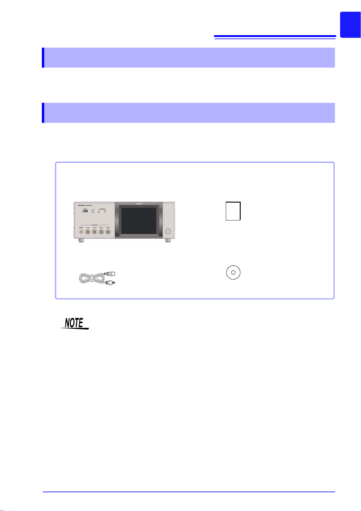
Confirm that these contents are provided.
IM3533 or IM3533-01 LCR Meter...........1 Instruction Manual (This document) ...... 1
Power Cord (2-line + ground)................. 1
LCR Application Disk ............................ 1
(Communications instruction manual [PDF
format], explanation of communications
commands, USB driver, sample application)
The latest version can be downloaded
from our web site.
Introduction
Thank you for purchasing the HIOKI Model IM3533, IM3533-01 LCR Meter. To obtain maximum performance from the instrument, please read this manual first, and keep it handy for future reference.
Verifying Package Contents
When you receive the instrument, inspect it carefully to ensure that no damage occurred during shipping.
In particular, check the accessories, panel switches, and connectors. If damage is evident, or if it fails to
operate according to the specifications, contact your authorized Hioki distributor or reseller.
1
• Probes, fixture are not supplied with the instrument as standard equipment. You should
order them separately, according to requirements.
• The instrument ships from the factory co nfig ured as descr ibed in "Appendix12 Initial Settings Table"(p. A18).
Transporting the instrument
Use the original packing materials when transporting the instrument, if possible.
See "Transporting the instrument" (p. 354)
Page 10
2
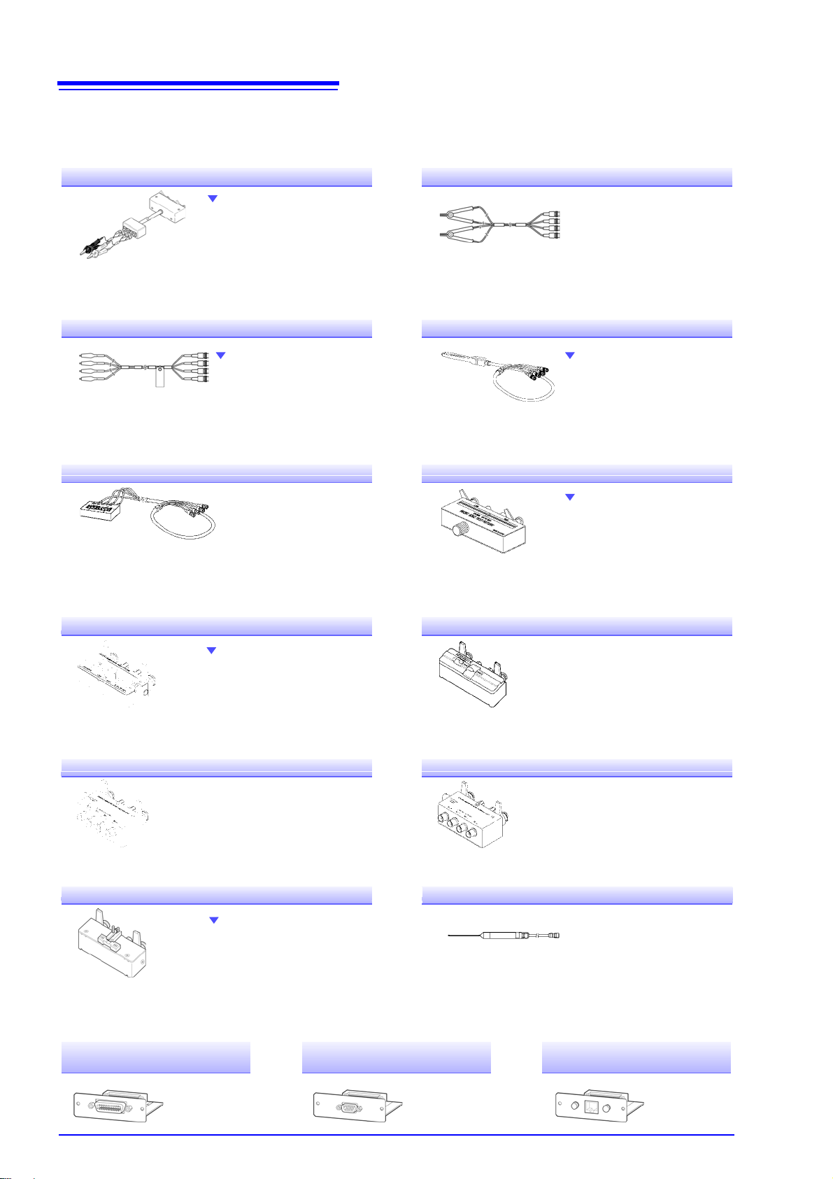
Measurable range: DC to 200 kHz
Maximum voltage:
±42 Vpeak (AC+DC)
Maximum current:
±1 Apeak (AC+DC)
Measurement terminal hole diameter: 0.3 mm to 5 mm
L2000 4-terminal Probe
Alligator-clip-type measurement probes. These generalpurpose dual-electrode clips fit
a wide range of conductor
thicknesses.
Measurable range: DC to 5 MHz
Maximum voltage: ±42 Vpeak (AC+DC)
Maximum current: ±1 Apeak (AC+DC)
Measurement terminal hole diameter: 0.3 mm to 5 mm
9140-10 4-terminal Probe
Measurable range: DC to 5 MHz
Maximum voltage:
±DC30 V
Electrode tip spacing: 0.3 mm to approx. 6 mm
Measurable range: DC to 1 MHz
Maximum voltage: DC
±40 V (42 Vpeak (Measurement signal + bias voltage))
Maximum current: 1 Apeak (Measurement signal + bias current)
Measurement terminal hole diameter: 0.3 mm to 2 mm
Rubber-sheathed alligator
clip type
9500-10 4-terminal Probe
Pincher type
9143-10 Pincher Probe
9261-10 Test Fixture
Measurable range: 42 Hz to 5 MHz
Maximum applied voltage: DC±40 V
Test sample dimensions: Lead diameter of 0.3 mm to 2 mm
Lead pitch of 5 mm or more
This fixture is for measuring
lead components. (less than
10 m residual resistance
after zero adjustment)
9262 Test Fixture
easurable range: DC to 5 MHz
Maximum applied voltage: DC
±40 V
Measurement terminal hole diameter: 0.3 mm to 1.5 mm
9263 SMD Test Fixture
This fixture is for measuring chip
components. (less than 10 m
residual resistance after zero adjustment)
Measurable range: DC to 120 MHz
Maximum applied voltage: DC±40 V
Test sample width of 3.5±0.5 mm or less
Measurable range: DC to 5 MHz
Maximum applied voltage: DC±40 V
Test sample dimensions: Test sample width of 1 to 10 mm
9677 SMD Test Fixture
9268-10 DC Bias Voltage Unit
Measurable range: 40 Hz to 2 MHz
Maximum applied current: DC2 A
Measurable range: 40 Hz to 5 MHz
Maximum applied voltage: DC
±40 V
9269-10 DC Bias Current Unit
This fixture is for the lower
electrode.
Measurable range: DC to 120 MHz
Maximum applied voltage: DC±40 V
Test sample dimensions: Test sample width of 1 to 4 mm
Test sample height of 1.5 mm or less
Platinum resistance bulb (Pt100), waterproof design
(EN60529:1991,IP67)
Measurable range: -10.0°C to 99.9°C
Tip diameter:
2.3 mm
Cord length: 1 m
9699 SMD Test Fixture 9478 Temperature Probe
Z3000
GP-IB Interface
Z3001
RS-232C Interface
Z3002
LAN Interface
Verifying Package Contents
Options
For more information, contact the store (distributor) from which you purchased the instrum ent or your ne are st
HIOKI sales office.
Page 11
3
Safety Information
Safety Information
This instrument is designed to comply with IEC 61010 Safety Standards, and has
been thoroughly tested for safety prior to shipment. However, mishandling during
use could result in injury or death, as well as damage to the instrument. However,
using the instrument in a way not described in this manual may negate the provided
safety features.
Be certain that you understand the instructions and precaution s in the manua l befo re
use. We disclaim any responsibility for accidents or injuries not resulting directly
from instrument defects.
This manual contains information and warnings essential for safe operation of the instrument and for maintaining it in safe operating condition. Be fo re u sing it, b e su re to ca re fully r ead the followin g sa fety pr ecautio ns.
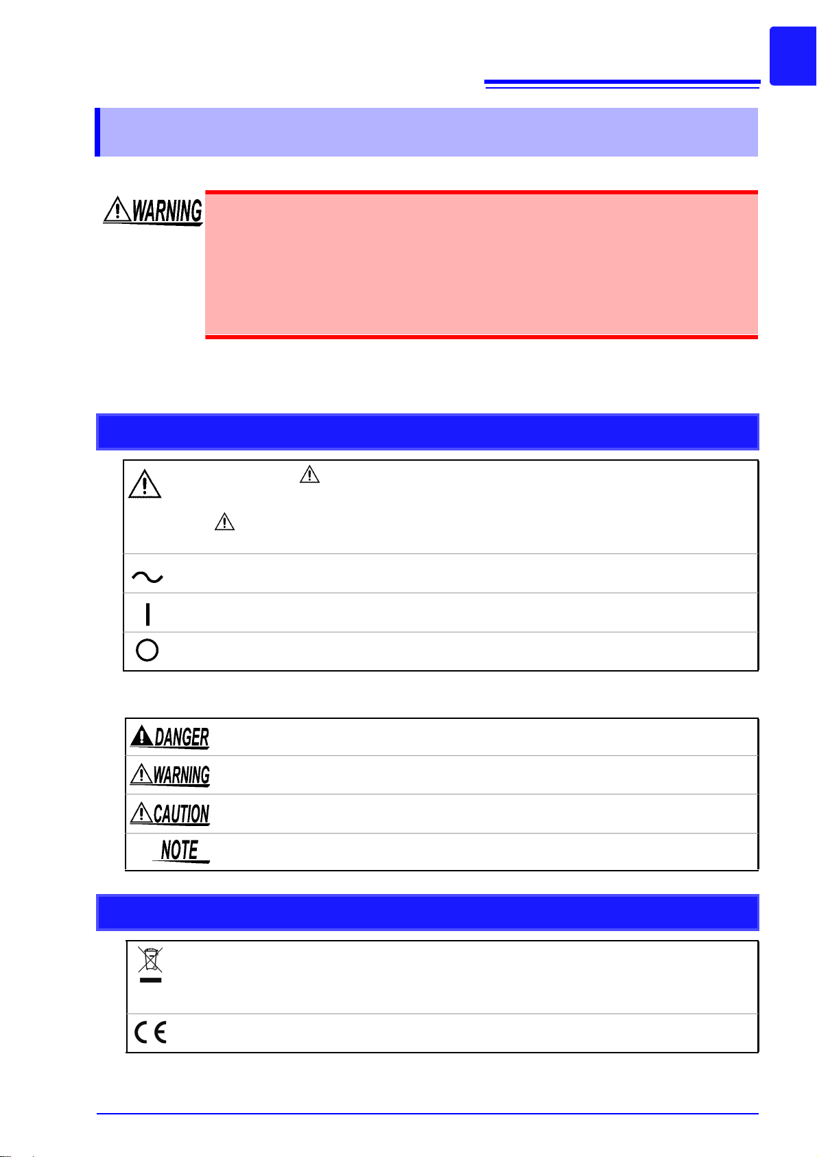
Safety Symbols
In the manual, the symbol indicates particularly importan t information that the user should
read before using the instrument.
The symbol printed on the product indicates that the user should refer to a corresponding
topic in the manual (marked with the symbol) before using the relevant function .
Indicates AC (Alternating Current).
Indicates the ON side of the power switch.
Indicates the OFF side of the power switch.
The following symbols in this manual indicate the relative importance of cautions and warnings.
Indicates that incorrect operation presents a significant hazard that could result in serious injury or death to the user.
Indicates that incorrect operation presents a significant hazard that could result in serious injury or death to the user.
Indicates that incorrect operation presents a possibility of injury to the user or damage
to the product.
Advisory items related to performance or correct operation of the product.
Symbols for Various Standards
WEEE marking:
This symbol indicates that the electrical and electronic appliance is put on the EU market
after August 13, 2005, and producers of the Member States are required to display it on the
appliance under Article 1 1.2 of Directive 2002/96/EC (WEEE).
This symbol indicates that the product conforms to safety regulations set out by the EC Directive.
Page 12
4
Safety Information
Notation
Symbols in this manual
Indicates the prohibited action.
p. )
* Indicates that descriptive information is provided below.
[ ]
CURSOR
(Bold character)
Windows
Dialogue
Indicates the location of reference information.
Menus, commands, dialogs, buttons in a dialog, and other names on the screen and the
keys are indicated in brackets.
Bold characters within the text indicate operating key labels.
Unless otherwise specified, “Windows” represents Windows 95, 98, Me, Widows NT4.0,
Windows 2000, Windows XP, Windows Vista or Windows 7.
Dialogue box represents a Windows dialog box.
Accuracy
We define measurement tolerances in terms of f.s. (full scale), rdg. (reading) and dgt. (digit) values, with
the following meanings:
f.s. (maximum display value or
scale length)
rdg. (reading or displayed value)
dgt. (resolution)
The maximum displayable value or scale length. This is usually the name
of the currently selected range.
The value currently being measured and indicated on the measuring instrument.
The smallest displayable unit on a digital measuring instrument, i.e., the in-
put value that causes the digital display to show a "1" as the least-significant digit.
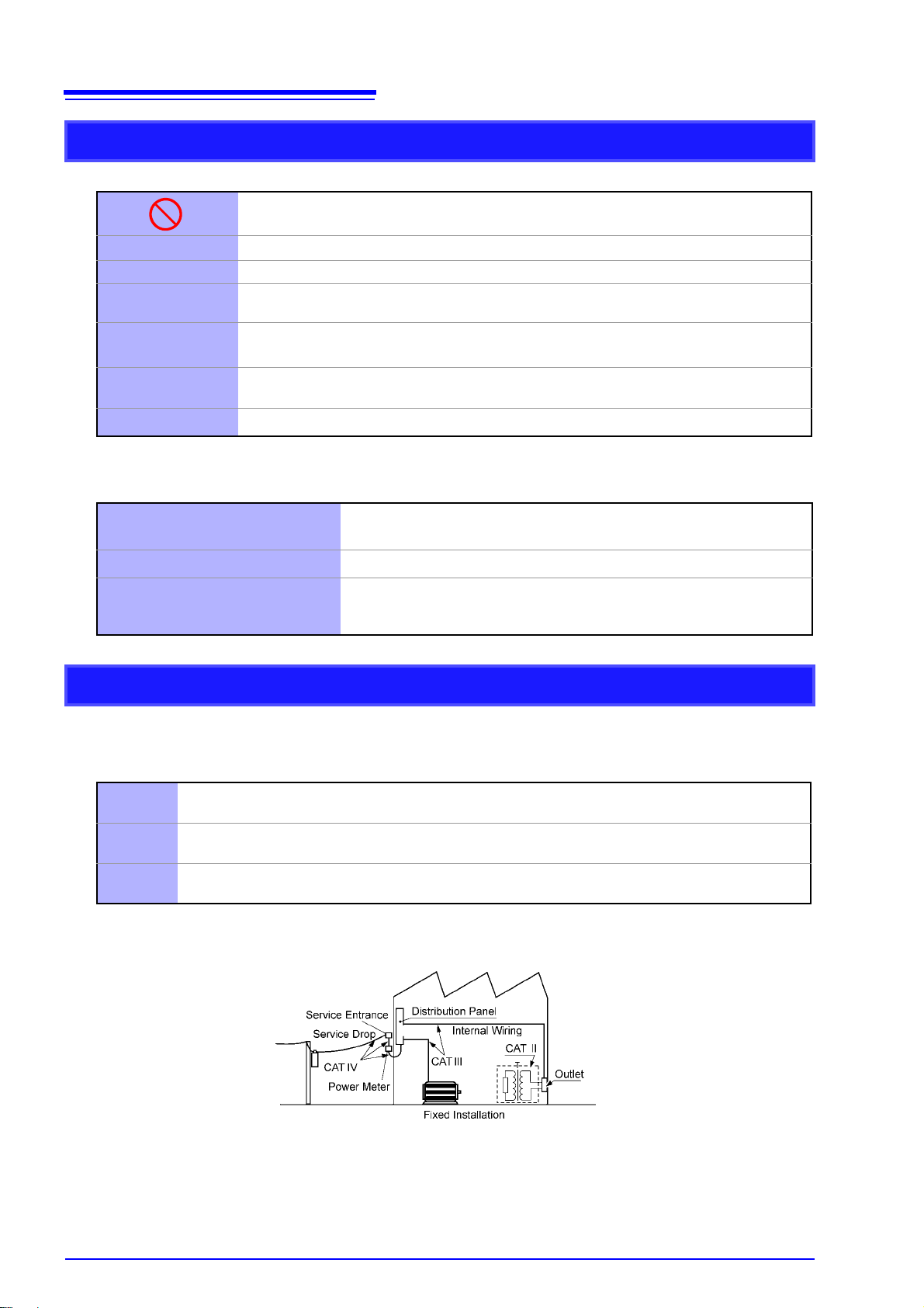
Measurement categories
To ensure safe operation of measurement instruments, IEC 61010 establishes safety standards for various electrical environments, cate gorized as CAT II to CAT IV, and called measurement categories. These
are defined as follows.
CAT II
CAT III
CAT IV
Primary electrical circuits in equipment connected to an AC electrical outlet by a power cord (portable
tools, household appliances, etc.) CAT II covers directly measuring electrical outlet receptacles.
Primary electrical circuits of heavy equipment (fixed installations) connected directly to the distribution
panel, and feeders from the distribution panel to outlets.
The circuit from the service drop to the service entrance, and to the power meter and primary overcurrent protection device (distribution panel).
Using a measurement instrument in an nvironment esignated with a higher-numbered category than that
for which the instrument is rated could result in a severe accident, and must be carefully avoided.
Page 13
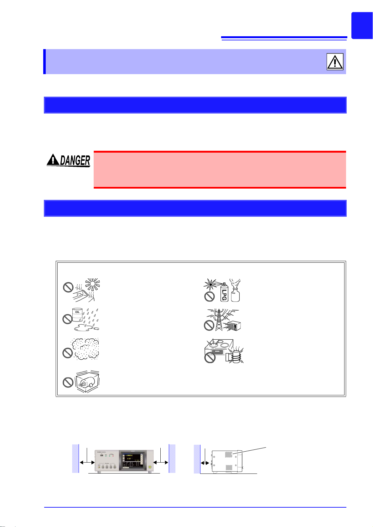
Operating Precautions
The instrument can be used with the stand (p. 11).
It can also be rack-mounted (p.A15).
50 mm or more 10 mm or more
Rear
50 mm or more
Vents
Operating Precautions
Follow these precautions to ensure safe operation and to obtain the full benefits of the various functions.
Preliminary Checks
Before using the instrument for the first time, verify that it operates normally to ensure the no damage
occurred during storage or shipping. If you find any damage, contact your authorized Hioki distributor or
reseller.
Before using the instrument, make sure that the insulation on the voltage cords is
undamaged and that no bare conductors are improperly exposed. Using the instrument in such conditions could cause an electric shock, so contact your dealer or
Hioki representative for replacements.
5
Instrument Installation
Operating temperature and humidity:
0 to 40°C (32 to 104°F), 20 to 80% RH or less, Indoors (non-condensating)
Storing temperature and humidity:
-10 to 55°C (14 to 131°F) 20 to 80% RH or less, Indoors (non-condensating)
Temperature and humidity range for guaranteed accuracy, 23
Avoid the following locations that could cause an accident or damage to the instrument.
Exposed to direct sunlight
Exposed to high temperature
Exposed to water, oil, other chemicals, or solvents
Exposed to high humidity or conden-
sation
Exposed to high levels of particulate
dust
Subject to vibration
±5°C, RH or less
In the presence of corrosive or explosive
gases
Exposed to strong electromagnetic fields
Near electromagnetic radiators
Near induction heating systems
(e.g., high-frequency induction heating
systems and IH cooking utensils)
To prevent overheating, be sure to leave the specified clearances around the instrument.
• The instrument should be operated only with the bottom or rear side downwards.
• The instrument must not be placed on an unstable table or tilted surface.
• Vents must not be obstructed.
Page 14

6
Operating Precautions
Shipping precautions
Hioki disclaims responsibility for any direct or indirect damages that may occur when this instrument has
been combined with other devices by a systems integrator prior to sale, or when it is resold.
Handling the Instrument
• To avoid electric shock, do not remove the instrument's case. The internal components of the instrument carry high voltages and may become very hot during operation.
• Do not allow the instrument to get wet, and do not take measurements with wet
hands. This may cause an electric shock.
• If the instrument exhibits abnormal operation or display during use, review the informa-
tion in "Inspection, Repair and Cleaning" (p. 353) an d "Err or disp lay" (p . 3 60) b efore con tacting your dealer or Hioki representative. Note that the instrument may be damaged if
the applied voltage or current exceeds the measurement range.
• This instrument is not designed to be entirely water- or dust-proof. Do not use it in an
especially dusty environment, nor where it might be splashed with liquid. This may cause
damage.
• To avoid damage to the instrument, protect it from physical shock when transporting and
handling. Be especially careful to avoid physical shock from dropping.
• Do not apply heavy downward pressure with the stand extended. The stand could be
damaged.
• Do not use excessive force on the touch panel, and do not use sharp objects that could
damage the touch screen.
• After use, always turn OFF the power.
This instrument may cause interference if used in residential areas. Such use must be
avoided unless the user takes special m easures to reduce electromagnetic emissions to
prevent interference to the reception of radio and television br oadcasts.
Before Turning Power On
• Before turning the instrument on, make sure the supply voltage matches that indicated
on its power connector. Connection to an improper supply voltage may damage the
instrument and present an electrical hazard.
• Be careful to avoid connecting the supply voltage improperly. Doing so may damage the
instrument's internal circuitry.
• To avoid electrical accidents and to maintain the safety specifications of this instrument,
connect the power cord only to a 3-contact (two-condu cto r + ground ) ou tle t.
• To av oid sho ck and short circuits, turn off the power to lines to be measured before mak-
ing connections to terminals to be measured and turning on the instrument.
Page 15

Operating Precautions
About Handling of Cords, Fixtures and Temperature probes
• For safety reasons, disconnect the power cord when the instrument is not used.To avoid
damaging the power cord, grasp the plug, not the cord, when unplugging it from the
power outlet.
• Do not apply a voltage to the measurement terminals. Doing so may damage the instru-
ment.
• When disconnecting the BNC connector, be sure to release the lock before pulling off the
connector. Forcibly pulling the connector without releasing the lock, or pulling on the
cable, can damage the connector.
• To avoid breaking the cables or probes, do not bend or pull them.
• Avoid stepping on or pinching cables, which could damage the cable insulation.
• Keep the cables well away from heat sources, as bare conductors could be exposed if the
insulation melts.Keep in mind that, in some cases, conductors to be measured may be hot.
• The sensor used in the temperature probe is a thin, precision platinum film. Be aware
that excessive voltage pulses or static discharges can destroy the film.
• Avoid subjecting the temperature probe tip to physical shock, and avoid sharp bends in
the leads. These may damage the probe or break a wire.
• When measuring high temperatures, do not let the handle of the temperature probe or
the compensation lead wire exceed the temperature range.
• The temperature probe has a protective nylon cap fitted on the end of the probes.
Remove the cap before using the probe.
• Put the protective cap back on the connector when not in use. If the protective cap is not
properly inserted, dust or other foreign matter may enter the connector and cause damage.
• The sheath of the temperature probe is filled with magnesium oxide powder. If the probe
is broken, the magnesium oxide powder may spill out. Be careful not to subject the
sheath to excess stress. Inhaling large quantities of magnesium oxide may be hazardous
to your health.
7
• Use only the specified connection cables. Using a non-specified cable may result in
incorrect measurements due to poor connection or other re asons.
• Before using a fixture or the like, read the instruction manual supplied with the product to
be used.
Before Connecting EXT I/O
To avoid electric shock or damage to the equipment, always observe the following
precautions when connecting to the EXT I/O connector.
• Always turn off the power to the instrument and to any devices to be connected
before making connections.
• Be careful to avoid exceeding the ratings of external terminals (p. 326).
• During operation, a wire becoming dislocated and contacting another conductive
object can be serious hazard. Use screws to secure the external connectors.
• Properly insulate any devices and mechanisms to be connected to the EXT I/O connector.
• The ISO_5V pin of the EXT I/O connector is a 5V power output. Do not apply external power to this pin.
Page 16
8
Operating Precautions
Input modules (option)
Before replacing the input module
• To avoid electric shock accident, before removing or replacing an input module, confirm
that the instrument is turned off and that the power cord and connection cables are disconnected.
• The mounting screws must be firmly tightened or the input module may not perform to
specifications, or may even fail.
• Always turn both devices OFF when connecting and disconnecting an interface connec-
tor.
Otherwise, an electric shock accident may occur.
When not using an input module (option)
To avoid the danger of electric shock, never operate the instrument with an input module
removed. To use the instrument after removing an input module, be sure to attach the blank
panel.
Handling the LCR Application Disk
• Always hold the disc by the edges, so as not to make fingerprints on the disc or scratch
the printing.
• Never touch the recorded side of the disc. Do not place the disc directly on anything
hard.
• Do not wet the disc with volatile alcohol or water, as there is a possibility of the label print-
ing disappearing.
• To write on the disc label surface, use a spirit-based felt pen. Do not use a ball-point pen
or hard-tipped pen, because there is a danger of scratching the surface and corrupting
the data. Do not use adhesive labels.
• Do not expose the disc directly to the sun's rays, or keep it in conditions of high tempera-
ture or humidity, as there is a danger of warping, with consequent loss of data.
• To remove dirt, dust, or fingerprints from the disc, wipe with a dry cloth, or use a CD
cleaner. Always wipe from the inside to the outside, and do no wipe with circular movements. Never use abrasives or solvent cleaners.
• Hioki shall not be held liable for any problems with a computer system that arises from
the use of this LCR Application Disk, or for any problem related to the purchase of a Hioki
product.
Page 17
9
Temperature correction function
The temperature correction function lets you perform
even more precise DC resistance measurement.
TRANSFORMER mode (p. 193)
A dedicated screen allows you to measure transformers, coils, and other windings quickly and efficiently.
ANALYZER mode (IM3533-01 only) (p. 149)
The IM3533-01’s frequency sweep function lets you
measure frequency characteristics (list display only).
Wide range of measurement conditions (p. 50)
Capable of measurement under a wide range of measurement conditions: measurement frequencies from 1
mHz to 200 kHz and measurement signal levels from 5
mV to 5 V.
Capable of high-speed measurement
High-speed measurement is possible.
The IM3533 and IM3533-01 can perform measurements at speeds of up to 2 ms (typical values).
BIN function (p. 109)
With LCR mode, easily ranks measurement items into
up to 10 classifications based on the measurement
values.
CONTINUOUS measurement mode (p. 209)
Capable of consecutive measurements using measurement conditions stored in the memory of the instrument.
This function enables, for example, making pass/fail judgment with different measurement cond itions.
(Example: Performing C-D measurement with 120 Hz and Rs measurement with 100 kHz in succession)
Low impedance can be measured with
high degree of accuracy
LCR mode includes a setting for measuring low impedance with a high degree of accuracy.
Comparator function
LCR mode: (p. 102)
Capable of making HI/IN/LO pass/fail judgments
based on the measurement values for two parameters.
TRANSFORMER mode: (p. 193)
Capable of making HI/IN/LO pass/fail judgments for
calculation parameters.
Various interfaces supported
Supports the most suitable external I/O (handler interface)
for production lines, USB, GP-IB, RS-232C and LAN.
*GP-IB, RS-232C, and LAN interfaces are optional.
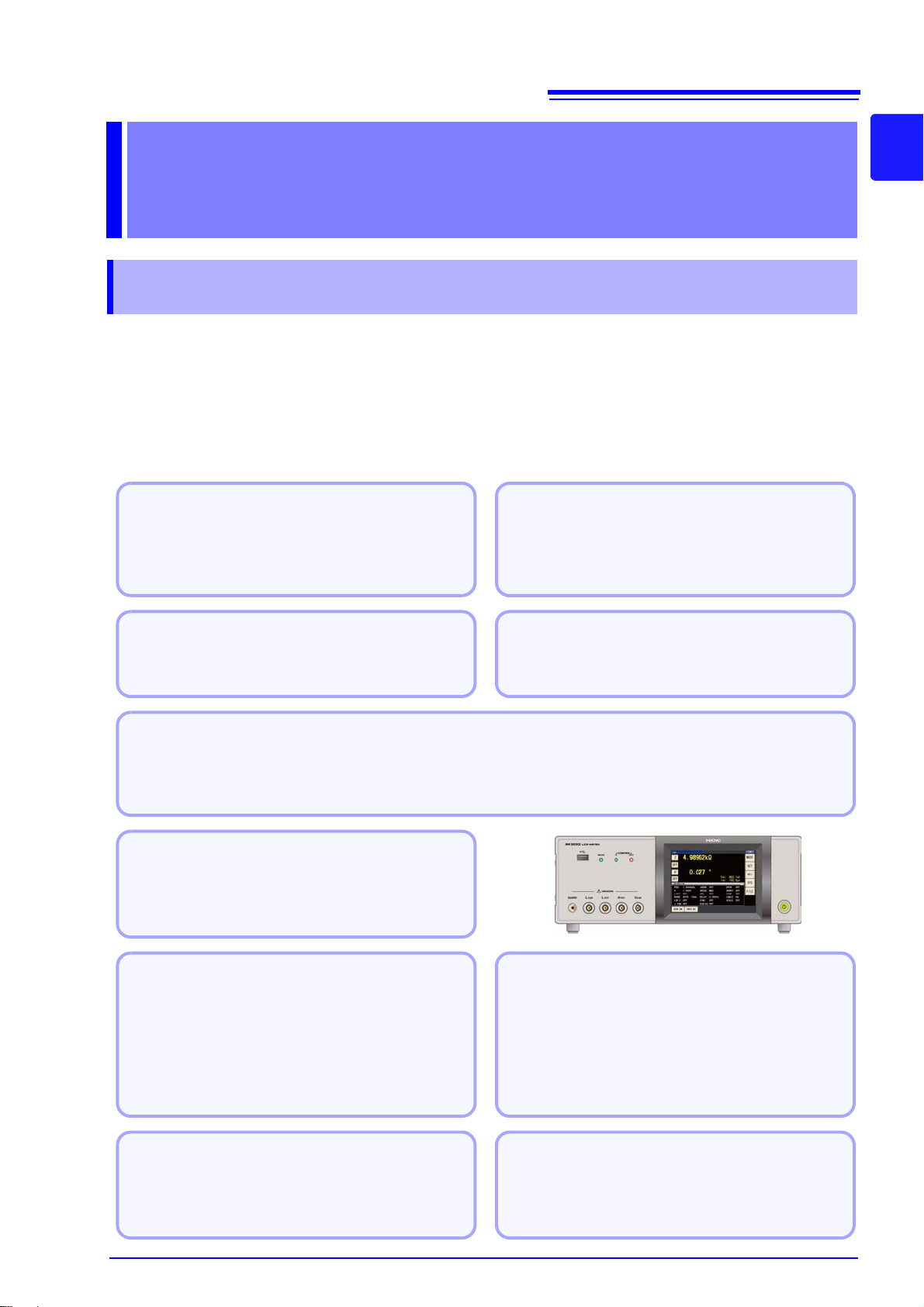
1.1 Product Overview Features
1
Overview Chapter 1
1.1 Product Overview Features
The HIOKI IM3533 and IM3533-01 LCR METER is an impedance measuring instrument which achieves
high speed and high accuracy.
With measurement frequencies of 1 MHz to 200 kHz and measurement signal levels of 5 mV to 5 V, the
instrument allows you to configure a broad range of measurement conditions. Additionally, features such as
a dedicated transformer and coil mea surement screen , DC resistance measurement with temperature correction, and a ANALYZER function (IM3533-01 only) m ake the IM3 533 a nd IM 3533-01 excellent choices for
use in a wide range of applications, from transformer and coil pro duction lines to research and d evelopment.
Chapter 1 Overview
Page 18
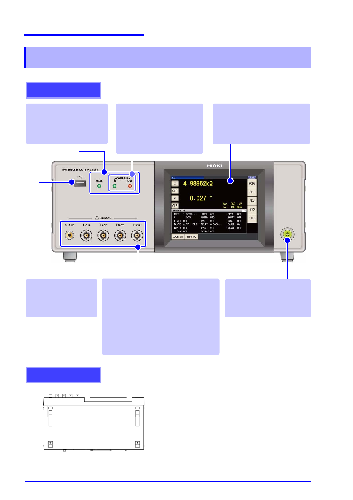
10
Front
Measurement LEDs
Lights during measurement.
Standby Key
Toggle standby state (p. 35)
(The main power switch is located
at the rear.)
Front USB connecter
Connect a USB flash drive
storage device. (p. 274)
Measurement Terminals
Connect measurement cables or a fixture. (p. 32)
•H
CUR
jack: Current source terminal
•H
POT
jack: Detected voltage high terminal
•L
POT
jack: Detected voltage low terminal
•L
CUR
jack: Measurement current detected
terminal
• GUARD jack: Sh ield (measurement
ground) terminal
LCD Display
This is a touch panel display.
Press the keys displayed on the
screen to operate the instrument.
Judgment Result
Indication LEDs
Indicates the judgment results for
comparator and BIN measurement.
LCR mode (p. 102)
TRANSFORMER mode (p. 193)
(Example: IM3533)
This instrument can be rack mounted.
See "Appendix10 Rack Mounting"(p. A15)
Parts removed from this instrument should be
stored in a safe place to enable future reuse.
Bottom Panel
1.2 Names and Functions of Parts
1.2 Names and Functions of Parts
Page 19
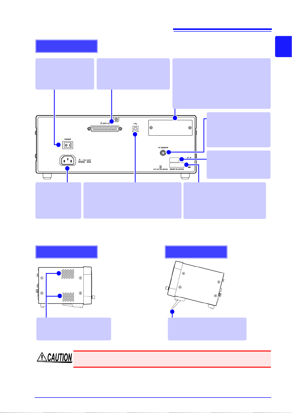
Rear
Power Inlet
Connect the supplied
power cord (p. 31).
USB Connector
Connect to a computer to control the instrument
with communication commands
(Ref to Communication Instruction Manual (LCR
Application Disk)
.
Interface port
Install optional interfaces.
(p. 263), Communication Instruction Manual
(LCR Application Disk)
• Z 3000 GP-IB Interface
• Z3001 RS-232C Interface
(When using a printer)
• Z3002 LAN Interface
Right side
Stand
Enables the instrument to be tilted.
Left side
Vents
Keep clear of obstructions (p. 5).
Power Switch
(Main power)
Turns the power on and off.
(p. 35).
Manufacturer's Serial Number
Shows the serial number.
Do not remove this label, as it is required
for product support.
MAC address of the LAN
(p. 264), (Ref to Communication Instruction Manual (LCR
Application Disk)
EXT I/O Connector
Connect to a PLC or I/O board to
control measurement start, and to
acquire comparator results (p. 309).
TC sensor terminal
Connect a temperature probe
to convert resistance values
to reference temperatures
(p. 33), (p.A13).
11
1.2 Names and Functions of Parts
1
Chapter 1 Overview
Do not apply heavy downward pressure with the stand extended. The stand could be damaged.
Page 20
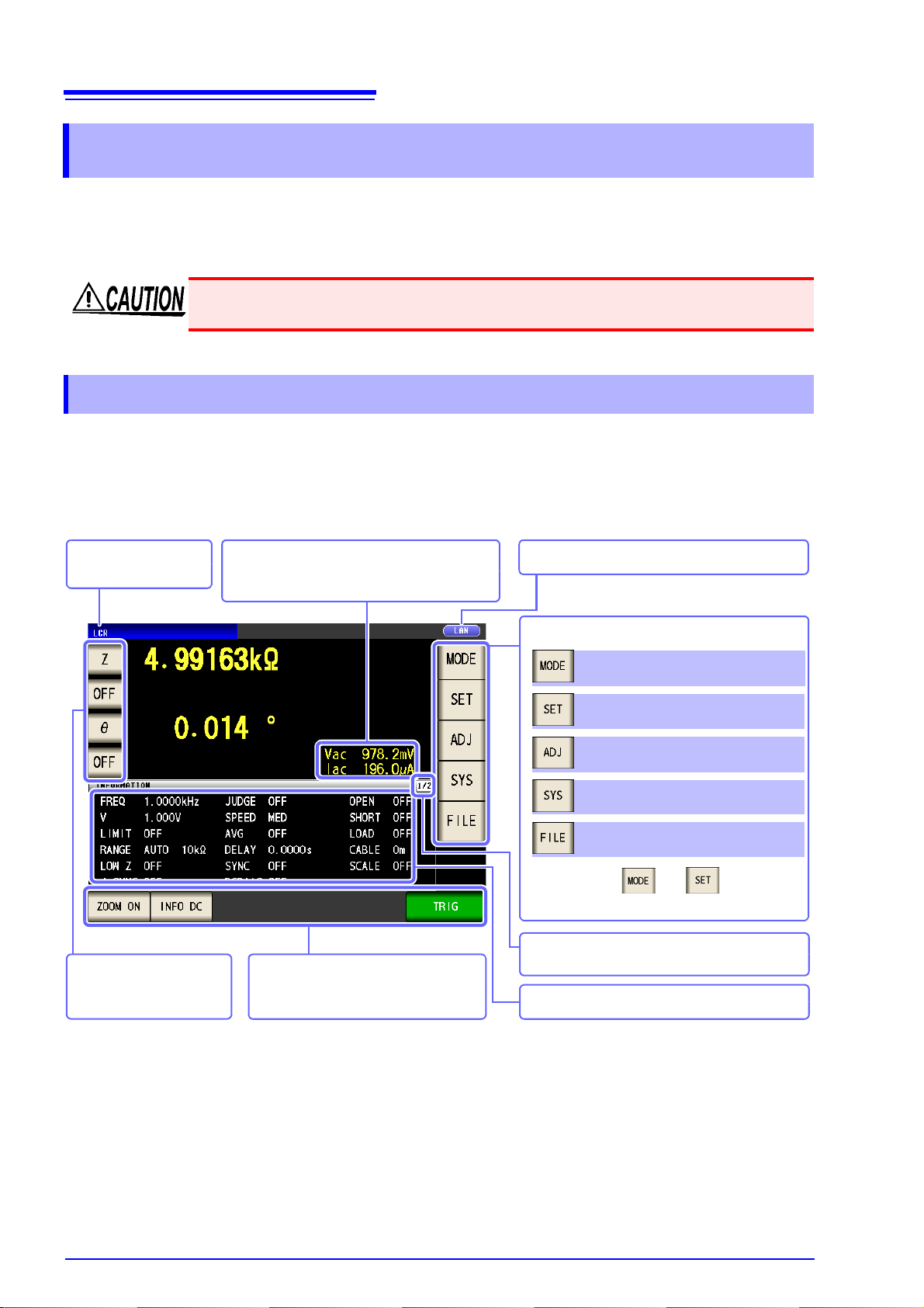
12
Operation keys
An operation key is displayed depending
on the situation (p. 45).
Parameter keys
Set each parameter (p. 28).
Indicates the selected
measurement mode.
The settings of and differ depending on the measurement mode.
Menu keys
Set the compensation (p. 24).
Set the system (p. 25).
Set the save settings (p. 27).
Set the advanced settings (p. 14).
Select the measurement mode (p. 13).
Indicates the interface that is currently set.
Indicates the measurement conditions.
Monitor values
Vac, Vdc: Voltage across the sample terminals
Iac, Idc: Current passing through the sample
Indicates the number of pages of measurement
conditions that can be displayed.
1.3 Screen Configuration and Operation
1.3 Screen Configuration and Operation
This instrument allows you to use a touch panel to set and change all measur ement conditions.
Gently touch a key on the screen to select the item or numerical value set for that key.
A selected key turns black.
In this manual, to gently touch the screen is referred to as "press".
Do not use excessive force on the touch panel, and do not use sharp objects that could
damage the touch screen.
1.3.1 Initial Screen
This is the screen that is first displayed when the power is turned on. It allows you to perform measurement
while checking the measurement conditions.
When the power is turned on again, display is in accordance with the measurement mode used immediately
before the power was turned off.
Page 21
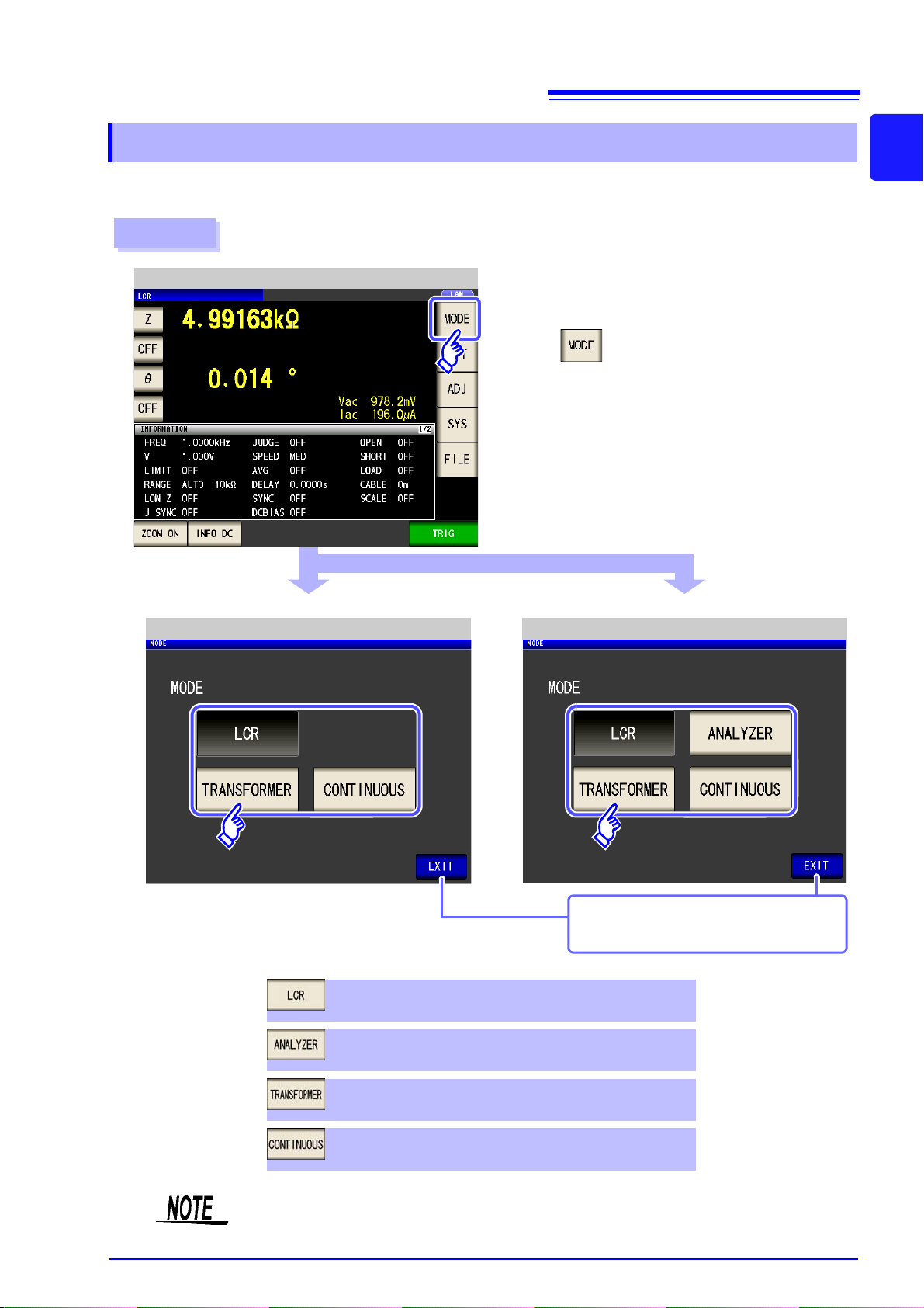
13
Procedure
2
1
When IM3533
When IM3533-01
Measurement Screen
Mode Selection (IM3533) Mode Selection (IM3533-01)
Press .
ANALYZER mode (IM3533-01 only) (p. 149)
TRANSFORMER mode (p. 193)
Select the measurement mode.
LCR mode (p. 45)
CONTINUOUS measurement mode (p. 209)
Displays the measurement screen for the
selected mode.
1.3 Screen Configuration and Operation
1.3.2 Measurement Mode Selection Screen
Select the measurement mode.
1
Chapter 1 Overview
After changing the measurement mode, check all settings (including co mpe nsation) be fore
performing measurement.
Page 22
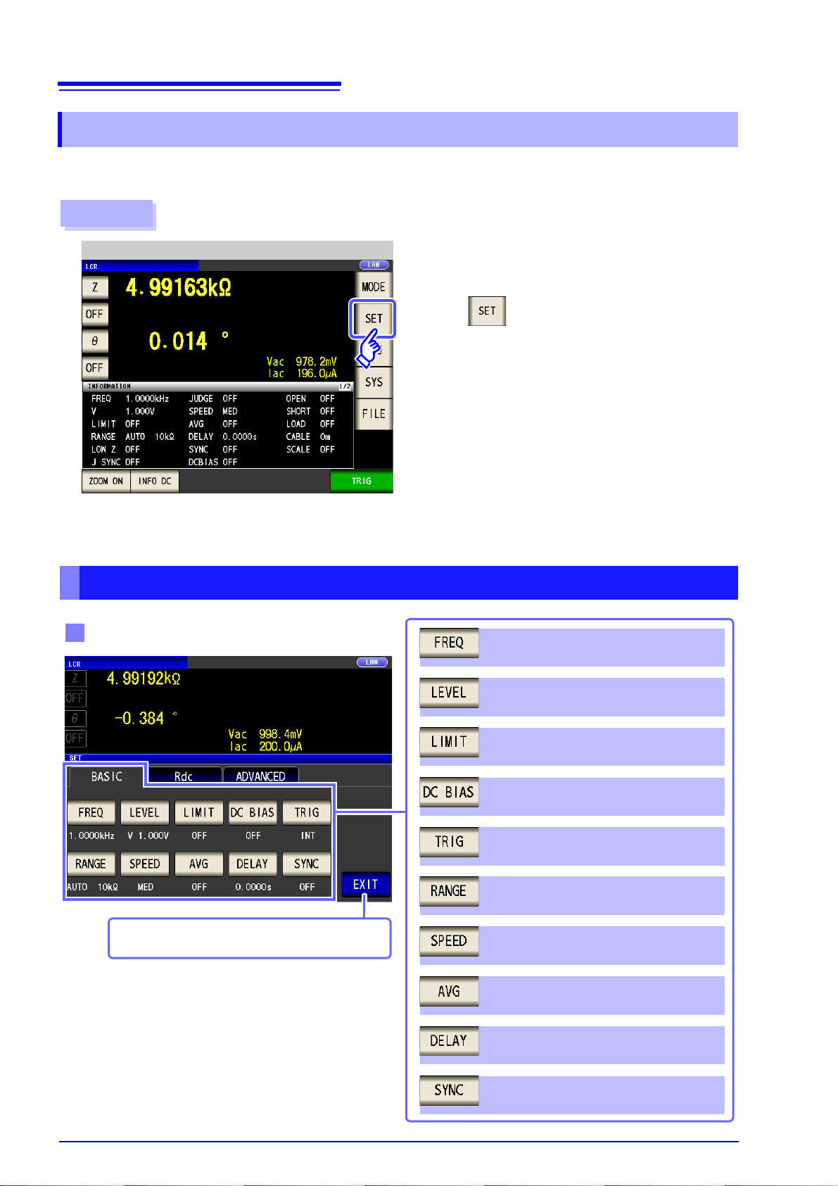
14
Press .
Measurement Screen
Configure settings for LCR mode, TRANSFORMER mode, and CONTINUOUS measurement mode.
On the IM3533-01, you can also configure ANALYZER mode settings.
Procedure
Basic setting
Trigger synchronous output function
setting (p. 77)
Measurement frequency setting (p. 50)
Measurement signal level setting (p. 52)
Voltage and current limit settings (p. 56)
DC bias setting (p. 58)
Trigger setting (p. 60)
Measurement range setting (p. 62)
Measurement speed setting (p. 73)
Average setting (p. 74)
Trigger delay setting (p. 76)
LCR mode measurement screen is displayed.
1.3 Screen Configuration and Operation
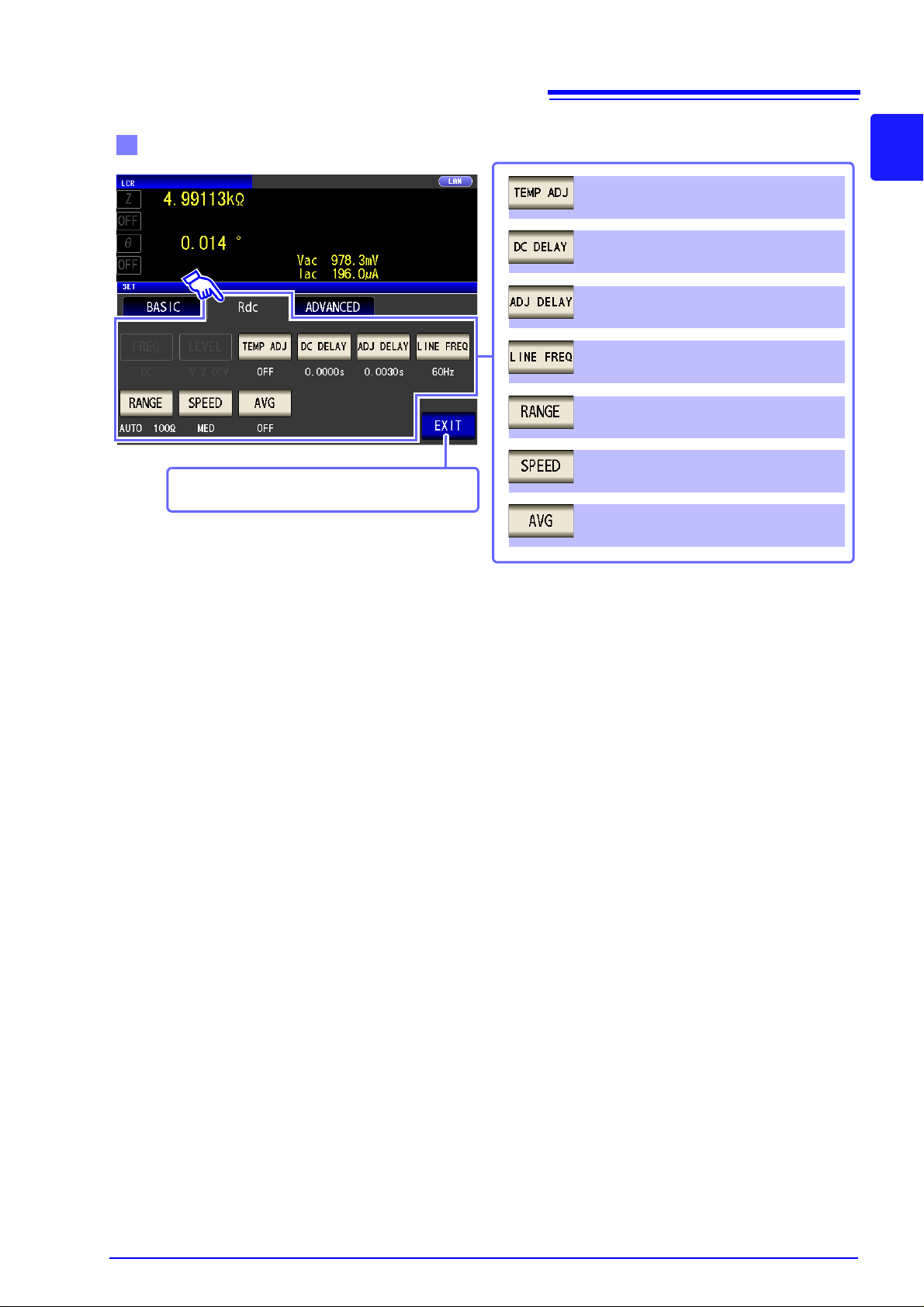
1.3.3 Advanced Settings Screen
This screen is for configuring the measurement conditions you want to change and other advanced settings.
Select the measurement mode (p. 13) before configuring the advanced settings.
LCR Mode
Page 23
15
Measurement range setting (p. 88)
DC resistance measurement setting
Line frequency setting (p. 87)
Average setting (p. 99)
DC delay setting (p. 83)
T emperature correction function setting (p. 8 1)
Adjustment delay setting(p. 85)
Measurement speed setting (p. 98)
LCR mode measurement screen is displayed.
Measurement range setting (p. 97)
1.3 Screen Configuration and Operation
1
Chapter 1 Overview
Page 24
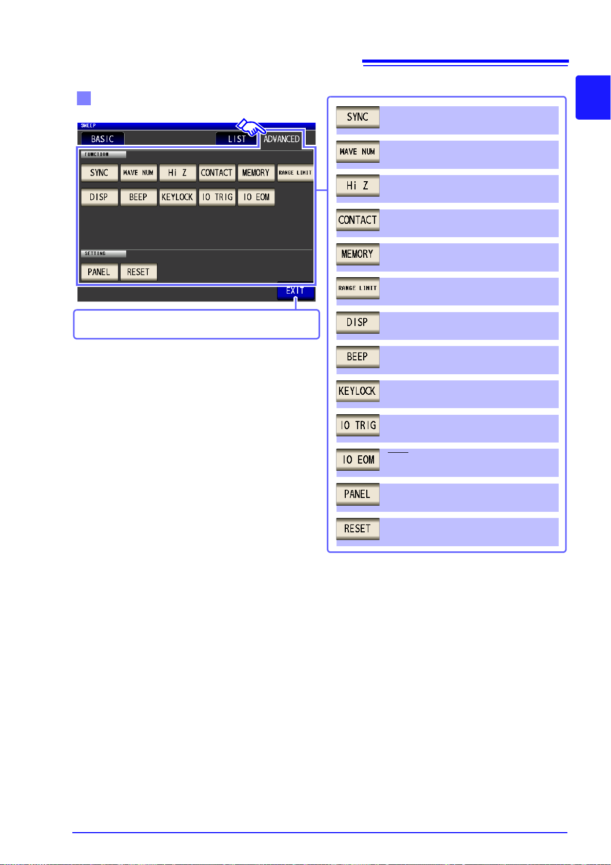
16
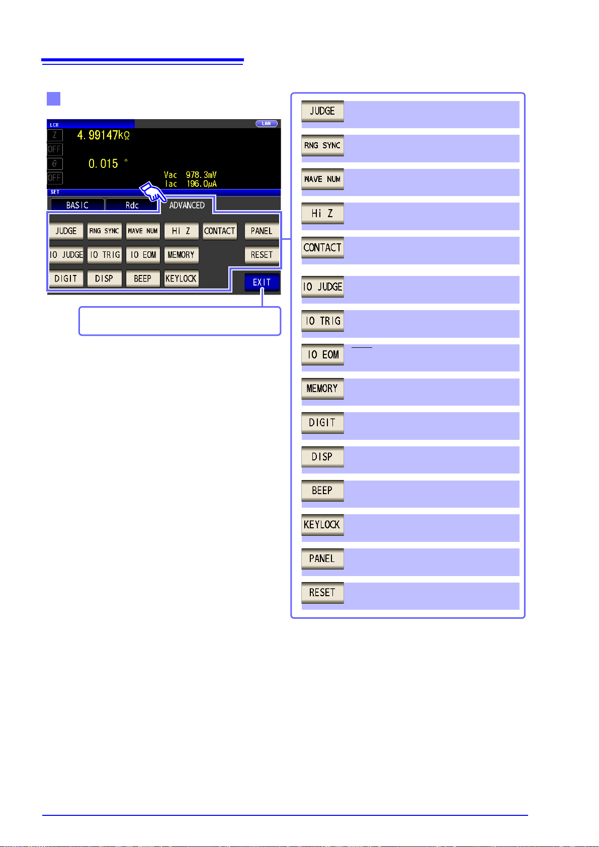
Contact check function setting (p. 132)
Application settings
Measurement result judgment setting
(p. 100)
Save settings of measurement results
(p. 138)
Panel loading and saving (p. 249)
System reset (p. 147)
Waveform averaging function setting
(p. 128)
Range synchronization function setting
(p. 120)
I/O output setting of judgment results
(p. 134)
I/O trigger setting (p. 136)
HIGH-Z reject function setting (p. 130)
Number of display digits setting for each
parameter (p. 140)
LCD setting (p. 142)
Beep sound setting(p. 141)
Key-lock setting (p. 144)
EOM Output Method Setting (p. 137)
LCR mode measurement screen is displayed.
1.3 Screen Configuration and Operation
Page 25
17
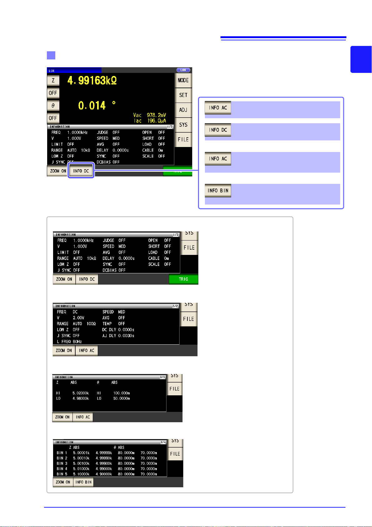
Checking the setting information
You can check the settings on the measurement
screen.
The key display will vary depending on what type
of information is being displayed.
Displays information regarding the
AC signal.
Displays information regarding the
DC signal.
Displays information about comparator
measurement judgment standards.
Displays information about BIN measurement judgment standards.
When using comparator measurement
When using BIN measurement
When displaying AC signal (AC) information
When displaying DC signal (DC) information
When displaying information about comparator measurement judgment standards
When displaying information about BIN measurement judgment standards
1.3 Screen Configuration and Operation
1
Chapter 1 Overview
Page 26
18
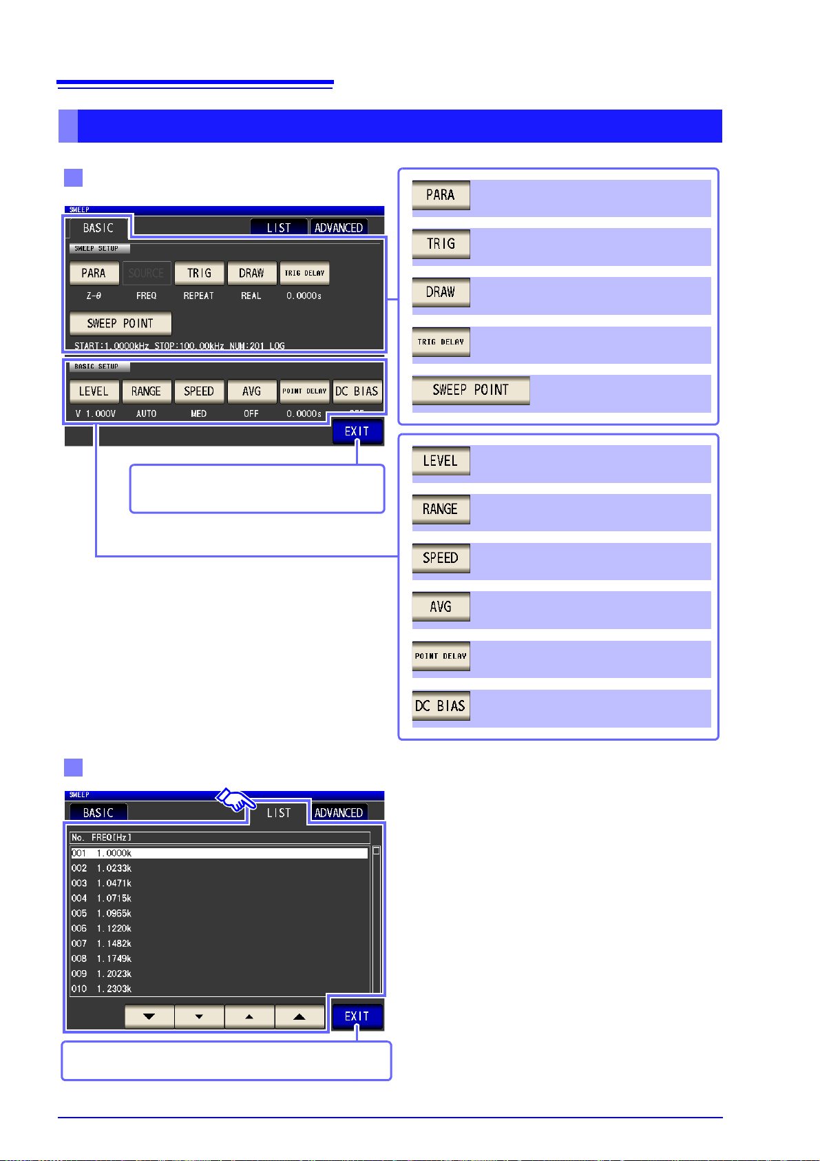
Measurement signal level setting (p. 158)
Measurement range setting (p. 160)
Measurement speed setting (p. 166)
Average setting(p. 167)
Point delay setting (p. 168)
Basic setting
DC bias setting (p. 169)
Measurement parameter setting(p. 150)
Trigger delay setting (p. 153)
Sweep point setting (p. 155)
Trigger setting (p. 151)
Display timing setting(p. 152)
ANALYZER mode measurement screen is
displayed.
List
ANALYZER mode measurement screen is displayed.
1.3 Screen Configuration and Operation
ANALYZER Mode (IM3533-01 only)
Page 27
19
Beep sound setting (p. 185)
Key-lock setting (p. 186)
Backlight setting (p. 184)
Panel loading and saving (p. 251)
System reset (p. 191)
Application settings
Contact check function setting (p. 177)
IO trigger setting (p. 189)
Waveform averaging function setting
(p. 173)
AUTO range limit function (p. 180)
EOM output method setting (p. 190)
Trigger synchronous output function
(p. 171)
HIGH-Z reject function setting (p. 175)
Save settings of measurement results
(p. 177)
ANALYZER mode measurement screen is displayed.
1.3 Screen Configuration and Operation
1
Chapter 1 Overview
Page 28
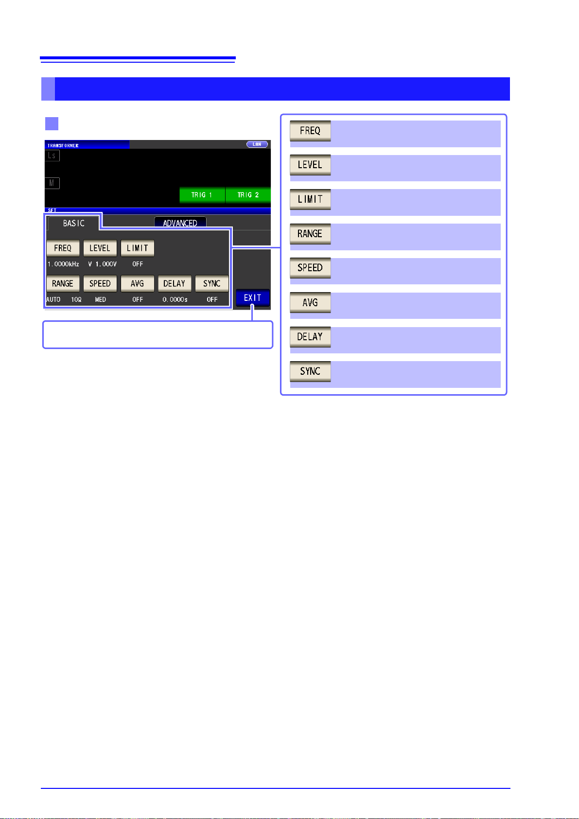
20
Basic setting
Trigger synchronous output function
(p. 77)
Measurement frequency setting (p. 50)
Measurement signal level setting (p. 52)
Voltage and current limit settings (p. 56)
Measurement range setting (p. 62)
Measurement speed setting (p. 73)
Average setting (p. 74)
Trigger delay setting (p. 76)
TRANSFORMER mode measurement screen is displayed.
1.3 Screen Configuration and Operation
TRANSFORMER Mode
Page 29
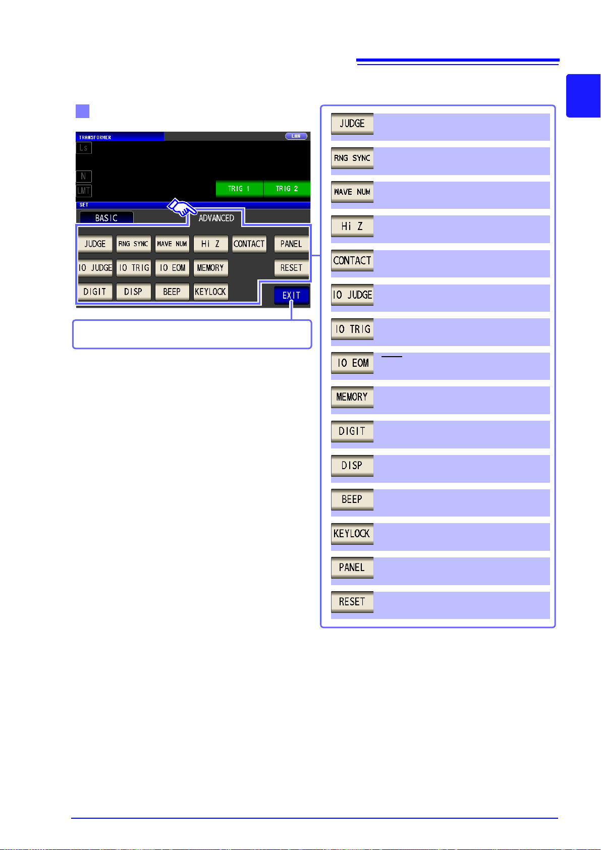
Application settings
Measurement result judgment setting
(p. 199)
Save settings of measurement results
(p. 138)
Panel loading and saving (p. 249)
System reset (p. 147)
Waveform averaging function setting
(p. 128)
Range synchronization function setting
(p. 120)
I/O output setting of judgment results
(p. 134)
I/O trigger setting (p. 136)
HIGH-Z reject function setting (p. 130)
Number of display digits setting for each
parameter (p. 140)
LCD setting (p. 142)
Beep sound setting (p. 141)
Key-lock setting (p. 144)
EOM Output Method Setting (p. 137)
TRANSFORMER mode measurement screen is displayed.
Contact check function setting (p. 132)
21
1.3 Screen Configuration and Operation
1
Chapter 1 Overview
Page 30
22
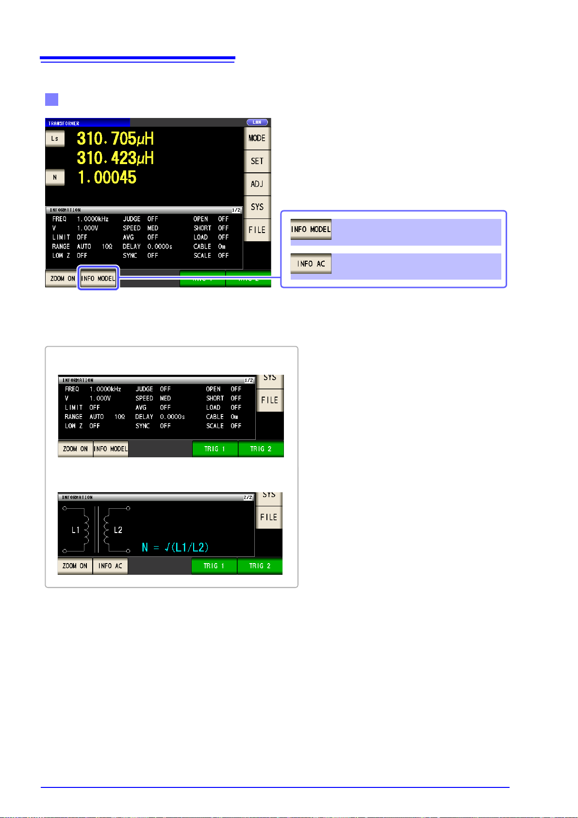
Checking the setting information
Displays the transformer model.
Displays information regarding the
AC signal.
You can check the settings on the measurement
screen.
The key display will vary depending on what type
of information is being displayed.
When displaying AC signal (AC) information
When displaying a transformer model
1.3 Screen Configuration and Operation
Page 31

23
Basic setting
Removes item from targets for
continuous measurement (p. 210)
Sets item as target for continuous
measurement (p. 210)
Removes all items from targets for
continuous measurement(p. 210)
Sets all items as targets for continuous
measurement (p. 210)
Displays panel information (p. 210)
CONTINUOUS measurement mode measurement
screen is displayed.
Application settings
Display timing setting (p. 213)
LCD setting (p. 214)
CONTINUOUS measurement mode measurement
screen is displayed.
1.3 Screen Configuration and Operation
CONTINUOUS Measurement Mode
1
Chapter 1 Overview
Page 32

24
Procedure
Press .
Measurement Screen
Set the compensation condition.
Open circuit compensation setting (p. 215)
Scaling setting (p. 246)
Cable length compensation setting (p. 245)
Short circuit compensation setting (p. 224)
Load circuit compensation setting (p. 232)
Measurement screen is displayed.
1.3 Screen Configuration and Operation
1.3.4 Compensation Settings Screen
Page 33

25
Procedure
Press .
Measurement Screen
To set the details of the system.
Interface type settings
Measurement screen is displayed.
Printer Setting (p. 331)
(Setting only available when the Z3001 is
installed.)
RS-232C Setting
(Ref to Communication Instruction Manual (LCR
Application Disk))
(Setting only available when the Z3001 is
installed.)
GP-IB Setting
(Ref to Communication Instruction Manual (LCR
Application Disk))
(Setting only available when the Z3000 is
installed.)
USB Setting
(Ref to Communication Instruction Manual (LCR
Application Disk))
(Standard setting)
LAN Setting
(Ref to Communication Instruction Manual (LCR
Application Disk))
(Setting only available when the Z3002 is
installed.)
1.3 Screen Configuration and Operation
1.3.5 System Settings Screen
1
Chapter 1 Overview
Page 34

26
Check the version of the instrument
(p. 264)
Measurement screen is displayed.
Checking the Display Screen
Panel test (p. 265)
ROM/RAM test (p. 270)
I/O test (p. 271)
Display test (p. 268)
Panel calibration (p. 266)
Measurement screen is displayed.
Setting the Date and Time
(p. 272)
Indicates the current date and time set on the instrument.
Accepts the set time and date.
Measurement screen is displayed.
1.3 Screen Configuration and Operation
Page 35

27
Procedure
Press .
Measurement Screen
Set the save destination and type.
Save the measurement condition
Saves the setting conditions (p. 293)
Selects a file (p. 275)
Displays the screen immediately above
(p. 275)
Switches operation buttons. (p. 275)
Measurement screen is displayed.
Save method setting
Save destination folder
setting (p. 291)
Save type setting (p. 277)
Measurement screen is displayed.
1.3 Screen Configuration and Operation
1.3.6 Save Settings Screen
1
Chapter 1 Overview
Page 36

28
Procedure
Select parameters.
Parameter SettingMeasurement Screen
Static capacitance in series equivalent circuit
mode (F)
Static capacitance in parallel equivalent circuit
Loss coefficient = tan
Reactance ()
Susceptance (S)
DC Resistance()
Effective resistance in series equivalent circuit
mode ESR = (
)
Effective resistance in parallel equivalent circuit mode (
)
Conductance (S)
Impedance ()
Admittance (S)
*Impedance phase angle ( ° ) *
Q factor
* The phase angle q is shown based on the impedance Z.
When performing measurements using admittance Y as the reference, the sign of the impedance Z phase angle will be reversed.
Press the key to set.
Inductance in series equivalent circuit mode
(H)
Inductance in parallel equivalent circuit mode
(H)
The fourth parameter key
The third parameter key
The first parameter key
The second parameter key
Temperature (C°)
Display no measurement parameter in the
chosen position.
Measurement Screen is
displayed.
1.3 Screen Configuration and Operation
This screen is for selecting the measurement parameters to display.
See "4.1.2 Setting Display Parameters" (p. 47), "Appendix7 Se ries Equivalent Circu it Mod e and P arallel Equivalen t Circuit M ode"(p. A11)
1.3.7 Parameter Settings Screen
Page 37

Measurement
9478 Sheath Type Temperature Probe
(Option)
• USB cable
• GP-IB cable (only when the Z3000 is connected)
• Printer (only when the Z3001 is connected)
(p. 331)
Connect the external interface (as needed)
4
• RS-232C cable (only when the Z3001 is connecte d)
• LAN cable (only when the Z3002 is connected)
• EXT I/O (p. 309)
Connecting the Power Cord (p. 31)
2
Installing the Instrument (p. 5)
Turning Power On (p. 35)
1
5
Make instrument settings
6
Connect to the test sample
After using the instrument, remove the test sample and turn off the power . (p. 35)
FrontRear
When measuring DC resistance, be sure to set the line frequency before performing measurement.
See "4.3.4 Setting the Line Frequency" (p. 87)
Check that the instrument’s power switch is turned off.
Connect measurement cables, optional Hioki probes or test fixture (p. 32)
3
Preparations Chapter 2
Be sure to read the "Follow these precautions to ensure safe operation and to obtain the full benefits of the
various functions." (p. 5) before installing and connecting this instrument.
Refer to "Appendix10 Rack Mounting"(p. A15) for rack mounting.
2.1 Preparation Flowchart
29
2.1 Preparation Flowchart
2
Chapter 2 Measurement Preparations
Page 38

30
Before using the instrument for the first time, verify that it operates normally to ensure that no damage
occurred during storage or shipping. If you find any damage, contact your authorized Hioki distributo r or
reseller.
Do not use the instrument if damage
is found, as electric shock or shortcircuit accidents could result. Contact
your authorized Hioki distributor or
reseller.
Metal Exposed
Is the power cord insulation torn, or is
any metal exposed?
1
No Metal Exposed
Peripheral Device Inspection
Is the insulation on a measurement
cable torn, or is any metal exposed?
Metal Exposed
If there is any damage, measured values may be unstable and measurement errors may occur. Replace the
cable with an undamaged one.
No Metal Exposed
If damage is evident, request repairs.
Yes
Instrument Inspection
When turning power on
No
2
The power cord may be damaged, or
the instrument may be damaged internally. Request repairs.
No
Yes
The instrument may be damaged
internally. Request repairs.
See "15.1 Inspection, Repair and
Cleaning" (p. 353)
"15.3 Error display" (p. 360)
An error indication
occurs (ERR)
No
Inspection complete
Is damage to the instrument evident?
Is there an error display on the Opening
screen?
Does the Opening screen appear (model no., version no.)?
Opening screen
2.2 Pre-Operation Inspection
2.2 Pre-Operation Inspection
Please read the "Follow these precautions to ensure safe operation and to obtain the
full benefits of the various functions." (p. 5) before use.
Page 39

31
1
Check that the instrument’s power switch is turned off.
2
Connect a power cord that matches the line voltage to
the power inlet on the instrument. (100 V to 240 VAC)
3
Plug the other end of the power cord into an outlet.
Turn of f the power before disconnecting the power cord.
Rear
Power inlet
2.3 Connecting the Power Cord
2.3 Connecting the Power Cord
Be sure to read the "Before Turning Power On" (p. 6), "About Handling of
Cords, Fixtures and Temperature probes" (p. 7) before connecting power.
2
Connect the power cord to the power inlet on the instrument, and plug it into an outlet.
Chapter 2 Measurement Preparations
Page 40

32
Connecting a measurement cable/fixture
Connect directly to the measurement jacks with
the label side up, and affix with the levers on the
left and right.
Points to pay attention to when making your own probe
• Use 50 coaxial cable for the measurement cable.
• Ensure that the length of the cable is the same as that set for the instrument.
(IM3533: 1 m, IM3533-01: 1 m/ 2 m/ 4 m)
• The cable length is defined as the length from the tip of the BNC connector to the tip of the probe electrode.
• Make the portion of the core wire that is exposed as short as possible.
• Connect the H
CUR
, L
CUR
, H
POT
, and L
POT
shield pairs at the measurement object side.
(Ensure that a shield is not connected to a core wire.)
Measurement Terminal
Configuration
Fixture
Normal mode
2.4 Connecting the Measurement Cables, Probes, or Fixture
2.4 Connecting the Measurement
Cables, Probes, or Fixture
Be sure to read the "About Handling of Cords, Fixtures and Temperature
probes" (p. 7) before connecting measurement cables, probes or test fixture.
Connect your measurement cables, optional Hioki probes or test fixture to the measurement terminals.
Refer to
See the instructions provided with the fixture for operating details.
"Options" (p. 2) for details.
• Basically, when you make a probe yourself, it may not be able to satisfy the specificatio ns
of this instrument.
See: "Options" (p. 2)
• If all four terminals are disconnected, a meaningless number may be displayed on the
unit.
Page 41

33
1
Check that the instrument’s power switch is
turned off.
2
Holding the connector, orient so that the arrow is on
the top and connect to the terminal.
The connector will lock in place with a clicking sound.
3
Gently pull on the connector (the part other than the
coupling) to verify that it has been connected properly.
Rear
Coupling
When disconnecting the temperature probe:
Grasp the connector’s coupling and disconnect the line by pulling
straight back.
OK
40 mm or more
2.5 Connecting a Temperature Probe
2.5 Connecting a Temperature Probe
Be sure to read the "About Handling of Cords, Fixtures and Temperature
probes" (p. 7) before connecting measurement cables, probes or test fixture.
2
Chapter 2 Measurement Preparations
The 9478 Sheath Type Temperature Probe’s measurement unit is located at the tip of th e
metal sheath. When measuring the internal temperature of a target object, insert the metal
sheath to a length of at least 40 mm in order to assure accurate measurement, as illustrated below:
Page 42

34
1
Unplug the instrument's power cord from the wall outlet.
Disconnect connection cords.
2
Remove the blank panel.
3
Paying attention to the orientation of the interface,
inset it firmly into place.
Rear
4
Secure the interface in place by tightening the two fixing screws with a Phillips head screwdriver.
When removing the interface:
Unplug the power cord from the wall outlet and perform the above
procedure in reverse to remove the interface.
1
Unplug the instrument's power cord from the wall outlet.
Disconnect connection cords.
2
Attach the blank panel and secure it in place by tightening the two fixing screws with a Phillips head
screwdriver.
Rear
Making measurements without reattaching the blank
panel will prevent the instrument from performing to its
specifications.
2.6 Connecting an Interface
2.6 Connecting an Interface
Be sure to read the "Input modules (option)" (p. 8) before connecting measurement cables, probes or test fixture.
Read this section before installing or replacing an optional interface or removing the interface and using the
instrument without it.
Installing an interface
You will need: A Phillips head screwdriver
When a removed interface will not be used
You can check information about the interface installed in the instrument on the screen.
See "10.1 Setting the Interface" (p. 263), "10.2 Checking the Version of the Instrument" (p. 264)
Page 43

2.7 Turning the Power On and Off
Power switch
Turn the POWER switch on ( | ).
Lights green
To ensure that measurements fulfill the
degree of accuracy described in the
specifications, , allow at least 60 minutes
warm-up before executing zero adjustment.
Turn the POWER switch off ( ).
Instrument settings are retained, even if the POWER switch is
turned off (backup function).
OFF
2.7 Turning the Power On and Off
Connect the power cord and voltage and current measurement cables before turning the main power on.
35
2
Chapter 2 Measurement Preparations
Turning main power on
If the main power switch is tuned off while the instrument is in the standby state, it will start
up in the standby state the next time the main power switch is turned on.
Turning main power off
When the power supply is interrupted by a power failure or the like, the instrument recovers
in the measurement mode used before the power failure.
Page 44

36
ON the main power in the state, hold down the front Standby Key 2 seconds approximately.
Lights red
What is the standby state?
The instrument is in the standby state when measurement has b een stopped and th e instrument is wa iting
for STANDBY key input to be detected. To allow STANDBY key input to be detected, some internal circuitry is operating with power consumption of approximately 4 W.
The instrument is in standby state, press the Standby Key on the front.
To ensure that measurements fulfill the degree of accuracy described in the specifications, allow the
instrument to warm up for at least 60 minutes after standby state operation is canceled.
Lights green
2.7 Turning the Power On and Off
Be on standby
To cancel the standby
Page 45

37
1
Connect the 9263 SMD test fixture to the measurement terminals.
For the connection procedure, refer to the
instruction manual supplied with the fixture.
2
Set the first parameter to Cs and the third parameter to D. (p. 46)
Trigger synchronous output function
setting: OFF (p. 77)
3
Set the measurement conditions.
Touch on the Measurement screen, select
the item you want to set, and set it as follows.
LCR Basic Settings
Measurement frequency: 1.0000 kHz
(p. 50)
Measurement signal mode:
Open circuit voltage (V) mode (p. 52)
Measurement signal level: 1.000 V (p. 52)
Measurement range: AUTO (p. 62)
Measurement speed: MED (p. 73)
Voltage and current limit: (p. 56)
Average: OFF (p. 74)
Trigger delay: 0.0000 s (p. 76)
Trigger: INT(p. 60)
DC bias: OFF (p. 58)
3.1 When LCR Mode
Measurement
Example Chapter 3
This chapter provides example measurement scenarios for LCR mode, ANALYZER mode (IM3533-01 only),
and TRANSFORMER mode.
3
3.1 When LCR Mode
Measuring a Laminated Ceramic Capacitor
Necessary items: 9263 SMD test fixture, Laminated ceramic capacity you want to measure
Chapter 3 Measurement Example
Page 46

38
4
Connect the test sample to the 9263 SMD test fixture.
For the connection procedure of the test sample, refer to the instruction manual supplied
with the fixture.
5
Check the measurement results.
• When you want to judg e the me as ur em e nt resu lts
See: "4.4.1 Judging with Upper and Lower Limit Values
(Comparator Measurement Mode)" (p. 102)
• When you want to save the measurement results
See: "4.5.8 Saving Measurement Results (Memory
function)" (p. 138)
3.1 When LCR Mode
Page 47

3.2 When ANALYZER Mode (IM3533-01 only)
1
Connect the 9262 Test Fixture to the measurement terminals.
For the connection procedure, refer to the
instruction manual supplied with the fixture.
Measurement signal mode:
Open voltage (V) mode (p. 158)
Measurement signal level:
1.000 V (p. 158)
POINT DELAY: 0.0000 s (p. 168)
2
ANALYZER Basic Settings
Range: AUTO (p. 160)
Parameter: Z- (p. 150)
Sweep method: REPEAT (p. 151)
Draw timing: REAL (p. 152)
Trigger delay: 0.0000 s (p. 153)
Set the measurement conditions.
Touch on the Measurement screen, select
the setting you wish to configure, and configure it
as follows.
Sweep range: 1.0000 kHz to
100.00 kHz (p. 155)
No. of sweep points: 201
Setting method: LOG
3
Connect the test sample to the 9263 Test Fixture.
3.2 When ANALYZER Mode (IM3533-01 only)
In ANALYZER mode, you can sweep through a user-specified range of frequencies.
See "Chapter 5 ANALYZER Function (IM3533-01)" (p. 149)
Measuring Element with Resonance Point
Necessary items: 9262 Test fixture, Element you want to measure
39
3
Chapter 3 Measurement Example
Page 48

40
4
Execute the sweep.
The sweep is repeated since TRIG is set to REPEAT.
• When you want to chec k the me asur em e nt va lue s.
See: "5.1.1 Measurement screen" (p. 149)
3.2 When ANALYZER Mode (IM3533-01 only)
Page 49

3.3 When TRANSFORMER Mode
1
Wire together the instrument and transformer together as shown below:
Primary side
Secondary side
Primary side
Secondary side
2
Set the measurement parameter to Ls and the computation parameter to N (p. 196), (p. 197).
Measurement frequency: 1.0000 kHz
(p. 50)
Volt age and current limit: OFF (p. 56)
Trigger synchronous output function:
OFF (p. 77)
Measurement range: AUTO (p. 62)
Measurement speed: MED (p. 73)
Average: OFF (p. 74)
Trigger delay: 0.0000 s (p. 76)
Measurement signal mode:
Open circuit voltage (V) mode (p. 52)
Measurement signal level: 1.000 V (p. 52)
3
Set the measurement conditions.
Touch on the Measurement screen,
select the item you want to set, and set it as fol-
lows.
LCR Basic Settings
3.3 When TRANSFORMER Mode
Measuring a transformer’s turn ratio
You will need: Switch cable and transformer to measure
41
3
Chapter 3 Measurement Example
Page 50

42
4
Wire together the primary side.
Primary side
Secondary side
Primary side
Secondary side
5
Execute the TRIG1 command.
Touch and measure the primary
side of the transformer.
6
Wire together the secondary side.
Primary side
Secondary side
Primary side
Secondary side
7
Execute the TRIG2 command.
Touch and measure the secondary
side of the transformer.
3.3 When TRANSFORMER Mode
Page 51

43
8
Check the measurement results.
• When you want to judge the measurement results
See"6.3 Judging with Upper and Lower Limit Values (Comparator
Measurement Mode)" (p. 199)
• When you want to save the measurement results
See"4.5.8 Saving Measurement Results (Memory function)" (p. 138)
3.3 When TRANSFORMER Mode
3
Chapter 3 Measurement Example
Page 52

44
3.3 When TRANSFORMER Mode
Page 53

45
An operation key is displayed depending on the situation.
Enlarges the screen (p. 49).
Operation keys
Displays the measurement conditions for DC
measurement (p. 17).
Saves the measurement data (p. 277).
Prints the measurement data (p. 331).
Displays the comparator settings (p. 17).
Displays the BIN settings (p. 17).
Displays the measurement conditions for AC
measurement (p. 17).
Indicates the name
of the loaded panel
(p. 256).
Parameter keys
Set each parameter
(p. 47).
Indicates error
messages and
other information
(p. 360).
Indicates the usage
status of internal
memory (p. 138).
Indicates that a
USB flash drive is
connected
(p. 273).
Indicates the
interface that is
currently set
(p. 263).
The settings of differ depending on the measurement mode.
Menu keys
Select the measurement mode (p. 13).
Set the details (p. 50).
Set the compensation (p. 215).
Set the system (p. 263).
Set the save settings (p. 273).
A measurement condition is displayed (p. 17).
Vac, Vdc: Voltage between the sample terminals
Iac, Idc: Current passing through the sample
4.1 About LCR function
LCR Function Chapter 4
4.1 About LCR function
The LCR function allows you to measure the impedanc e, phase angle, and other items by applying any frequency or level (effective value) signal to th e eleme nt you want to m easure. This function is su itable for evaluating the passive element of a capacitor, coil, or the like.
It allows you to perform measurement while checking the measurement conditions. When the power is turned on
again, display is in accordance with the measurement mode used immediately before the power was turned off.
For details on the screen configuration (p. 14).
The settings are synchronized between LCR mode, ANALYZER mode, and TRANS mode.
4.1.1 Measurement screen
4
Chapter 4 LCR Function
Page 54

46
4.1 About LCR function
When a measurement value is outside the guaranteed accuracy range, “Reference Value”
is displayed in the error display area. When this happens, the cause is likely to be one of the
following. Check the guaranteed accuracy range in "14.2 Measurement Range and Accuracy" (p. 342) and change the measurement conditions or you should consider the measured values as values for reference.
• Perhaps the test signal level is too low, increase the test signal level.
• If the current measurement range (during HOLD setting) is not appropriate, set again in the AUTO
range, or change the range by manual.
Page 55

4.1 About LCR function
Press the first parameter key.
LCR Measurement Screen
Example: The first parameter key: Capacitance Cs,
The third parameter key: Loss coefficient D
Procedure
Press .
Press to confirm the setting.
Parameter Setting
Press the third parameter key.
LCR Measurement Screen
4.1.2 Setting Display Parameters
You can select up to four measurement parameters to display in any location from 16 types.
See "1.3.7 Parameter Settings Screen" (p. 28)
"Appendix2 Measurement of High Impedance Components"(p. A3)
"Appendix7 Series Equivalent Circuit Mode and Parallel Equivalent Circuit Mode"(p. A11)
47
4
Chapter 4 LCR Function
Page 56

48
Press .
Press to confirm the setting.
Parameter Setting
Cs and D are set as the parameters.
LCR Measurement Screen
4.1 About LCR function
If is selected in the parameter setting, a measurement value is not displayed.
Page 57

49
Procedure
Press in the measurement screen to
display the magnification display screen.
When you want to show normal display:
Press in the magnification display
screen.
LCR Measurement Screen
Magnification Display Sc reen (W he n B IN)
Magnification Display Screen
(When Normal)
Magnification Display Scre en
(When Comparator)
• Indicates the position of the measurement value relative to the comparator
thresholds with a bar.
• The bars will not be displayed unless
both upper and lower limit values have
been set.
4.1 About LCR function
4.1.3 Enlarging Display of Measurement Values
The measurement values and comparator decision results can be displayed in enlarged form.
This function is convenient when the instrument is used under constant measurement conditions.
If the power is turned off when is displayed, will be displayed when the instrument starts the
next time you turn the power on.
4
Chapter 4 LCR Function
Page 58

50
LCR Measurement Screen
Example: Measurement frequency: 1 MHz
LCR Basic Settings
Procedure
Set each digit.
Set the frequency with the numeric keypad.
Frequency Setting (Digits) Frequency Setting (Numeric Keypad)
Press .
There are the following two frequency input methods.
Press or to change the input
method.
LCR Basic Settings
Settable range : 1 mHz to 200 kHz
4.2 Setting Basic Settings of Measurement Conditions
4.2 Setting Basic Settings of
Measurement Conditions
4.2.1 Setting the Measurement frequency
Set the frequency of the signal to apply to the test sample. For some test samples, the value may vary
depending on the measurement frequency.
Page 59

4.2 Setting Basic Settings of Measurement Conditions
Use the numeric keypad to enter the
frequency.
Press a instrument key to confirm the
setting.
Press to close the setting screen.
Use or to se lect the pos ition
of the decimal point and the instrument.
• Settable range : 1 mHz to 200 kHz
• The frequency is not confirmed until a instrument key is pressed.
• The instrument keys are disabled until a number
is entered.
• If you attempt to set a measurement frequency
greater than 200 kHz, it will automatically be
reduced to 200 kHz.
• If you attempt to set a measurement frequency
lower than 1 mHz, it will automatically be increased
to 1 mHz.
Sets the measurement frequency to x10.
Sets the measurement frequency to x .
10
1
If you make a mistake during input :
Press the to cancel the input so far, and
start again.
Frequency Setting (Digits) Frequency Setting (Numeric Keypad)
Frequency Setting (Digits) Frequency Setting (Numeric Keypad)
Use or to enter each digit of the
frequency.
Holding down a digit key changes the value continuously.
51
4
Chapter 4 LCR Function
Page 60

52
Open circuit voltage (V) mode
The value of the open circuit voltage is set.
Constant voltage (CV) mode
The value of the voltage between the terminals of the object under
test is set.
Constant current (CC) mode
The value of the current flowing through the object under test is set.
LCR Measurement Screen
1
LCR Basic Settings
Procedure
Press .
LCR Basic Settings
4.2 Setting Basic Settings of Measurement Conditions
4.2.2 Setting the Measurement signal level
The value of the test signal level may change according to the sample which is being tested.
This instrument is possible to vary the level of the test signal applied to the object under test over a wide
range using the following three methods. Selecting constant voltage or constant current mode will result in
increased measurement times due to use of software feedback control.
Do not switch between V, CV and CC while the test sample is still connected to the
measurement terminals because doing so may damage the test sample.
• In constant voltage (CV) mode, the generated voltage is controlled using software feed-
back so that the set constant voltage value is applied. Since the voltage used for the
most recent measurement is output as the enerated voltage initial value, a voltage in
excess of the set constant voltage value may be applied befor e feedback control is a ctive
if the sample’s impedance is higher than that of the last measured samp le.
• In constant current (CC) mode, the generated voltage is controlled using software feed-
back so that the set constant current value is applied. Since the volt age used for th e most
recent measurement is output as the generated voltage initial value, a current in excess
of the set constant current value may be applied before feedback control is active if the
sample's impedance is lower than that of the last measured sample.
Page 61

53
To select the measurement signal mode.
Open circuit voltage (V) mode (p. 54)
Constant voltage (CV) mode (p. 54)
Constant current (CC) mode (p. 55)
Measurement Signal Mode Setting
Use or to enter the voltag e or curr ent
value.
Measurement Signal Level Setting
See "For setting range and accuracy" (p. 54)
Normal measurement mode
Measurement signal mode Settable range
V, CV 0.005 V to 5.000 V
CC 0.01 mA to 50.00 mA
Low Z high accuracy mode
Measurement signal mode Settable range
V, CV 0.005 V to 2.500 V
CC 0.01 mA to 100.00 mA
The accuracy of testing varies according to the test
signal level.
See
"14.2 Measurement Range and Accuracy" (p. 342)
Press to close the setting screen.
4.2 Setting Basic Settings of Measurement Conditions
4
Chapter 4 LCR Function
When the measurement value is outside the guaranteed accuracy range, the following icon
appears at the top of the screen.
In this case, you should consider the following possible causes, and you should either
change the test conditions while checking the accuracy assured ranges "14.2 Measurement Range and Accuracy" (p. 342), or you should conside r the measur ed value s as va lues
for reference.
• Perhaps the test signal level is too low, increase the test signal level.
• If the current measurement range (during HOLD setting) is not appropriate , set again in the AUTO
range, or change the range by manual.
Page 62

54
Output impedance
Object under
test
CC
CV
HL
V
Constant current (CC) mode
You should select this if you wish
to set the current passing through
the object to be tested to a constant value.
Constant voltage (CV) mode
You should select this if you wish to set the
voltage across the terminals of the object
to be tested to a constant value.
Open circuit voltage (V) mode
This voltage value is the value which is applied across the two terminals of
the series combination of the object which is being tested and the output
impedance. As for the voltage which is applied across the terminals of the
object which is being tested (by itself), if required, you should either check
the monitor voltage value, or select constant voltage (CV) and set a voltage
value across these terminals.
Open circuit voltage (V) mode and Constant voltage (CV) mode setting
Xm
1–
2
fC
-----------------=
Zm = Rm + jXm = 0 [
] - j15.9 []
4.2 Setting Basic Settings of Measurement Conditions
About the test signal mode
Relationship between the measurement signal mode of the instrument and the sample is as follows.
For setting range and accuracy
Measurement mode (p. 72) Normal mode Low Z high accuracy mode
Open circuit voltage setting range 0.005 V to 5.000 V 0.005 V to 2.500 V
Open circuit voltage accuracy ±10%rdg. ±10 mV ±10%rdg. ±10 mV
Output impedance 100 ±10 25 ±5
Depending on the sample, you may not be able to perform constant voltage measurement. In
this situation, the following mark will be displayed:
Constant voltage measurement will not be performed.
Change the constant voltage level so that it is less than or equal to the displayed Vac monitor values.
Example: Range in which constant voltage operation is supported when measuring a 1 F
C at 10 kHz
The sample impedance
Zm is as follows:
Page 63

4.2 Setting Basic Settings of Measurement Conditions
Ro: Output resistance (100 [])Zm' = Ro + Zm = 100 [
] - j15.9 []
Vm
Zm Vo
Zm
----------------------
15.9
Vo
101.3
--------------------------
==
Vo: generator output
|Zm' |
15.9 [
] × Vo
Constant current (CC) mode setting
Xm 2fL=
Zm
= Rm + jXm = 0 [] - j6.28 []
Ro: output resistance (100 [])Zm' = Ro + Zm = 100 [
] - j6.28 []
Im
Vo
Zm
------------
Vo
118.1
----------------- -==
Vo: generator output
|Zm' |
Vo
100.2 [
]
The impedance Zm' observed from the generator is as follows:
55
Accordingly, the voltage
Because the generator output voltage range is 5[mV] to 5[V], the CV operation range per
the above expression is
In low Z high accuracy mode, the output resistance
The constant current operation range differs depending on the test sample to be measured.
Measurement mode (p. 72) Normal mode Low Z high accuracy mode
Constant current setting range 0.01 mA to 50.00 mA 0.01 mA to 100.00 mA
Constant current accuracy ±10%rdg. ±10 A ±10%rdg. ±10 A
Output impedance 100 ±10 25 ±5
Testin g some types of sample is not possible using constant current. In this case, the following
symbol appears on the display:
Vm across both leads of the sample is as follows:
Vm = 0.8[mV] to 0.78[V].
Ro becomes 25 [].
4
Chapter 4 LCR Function
Constant current measurement will not be performed.
Change the constant current level so that it is less than or equa l to the displayed Iac moni tor
values.
Example: When a 1 mH impedance is measured at 1 kHz, the CC operation range can be
obtained as follows.
Sample impedance
The impedance
Accordingly, the current
Because the generator output voltage range is 5 [mV] to 5 [V] (see the table of page 54),
the CC operation range per the above expression is
In low Z high accuracy mode, the output resistance
Zm becomes as follows:
Zm' observed from the generator is as follows:
Im across both leads of the sample is as follows:
Im = 49.9[A] to 49.9[mA].
Ro becomes 25 [].
Page 64

56
When open circuit voltage (V) mode or
constant voltage (CV) mode is set:
Set the current limit.
When constant current (CC) mode is set:
Set the voltage limit.
Procedure
LCR Measurement Screen
• You can check the measurement signal level on the monitor display.
• The monitor display is different for V, CV, and CC.
First set the measurement signal level, and thereafter set the voltage or current limit.
The setting for voltage or current limit changes automatically to current or voltage limit,
according to the present measurement signal mode setting.
See "4.2.2 Setting the Measurement signal level" (p. 52)
LCR Basic Settings
When the measurement signal level is a
voltage (V, CV)
Current Limit Setting
When the measurement signal level is a
current (CC)
Voltage Limit Setting
4.2 Setting Basic Settings of Measurement Conditions
Depending on the measurement signal level, in some cases it is possible to damage the sample which is
being tested by applying to it a voltage or a current greater than its rated value.
For this reason, set a limit value to restrict the voltage that can be applied to the test sample or current that
can flow to the test sample. Enabling the limit function will result in increased measurement times due to use
of software feedback control.
4.2.3 Limiting the Voltage and Current Applied to the Sample (Limit Values)
Page 65

57
Select ON/OFF for the limit function.
Disables the limit function.
Enables the limit function.
Current Limit Setting
Use or to enter the limit value.
Current Limit Setting
Limit range
Measurement
signal mode
Limit set Setting range
V, CV Current limit 0.01 mA to 100.00 mA
CC Voltage limit 0.005 V to 5 V
Current limit accuracy : ±10%rdg. ±10 mA
Voltage limit accuracy : ±10%rdg. ±10 mV
Example: When constant voltage (CV) setting
When the limit function is on, you may encounter a display such as the following.
When a voltage or current in excess of the applicable limit value is not applied to the sample so that
the measurement signal level setting is not
reached, changes to the measurement signal level
are canceled.
At this time, the voltage or current which exceeds
the limit value is not being applied to the sample
under test. You should change the test signal level
so that it does not exceed the limit value.
If the voltage or current which is applied to the
sample under test exceeds the limit value (the
current exceeding the limit value flows through
the sample even when the open-circuit voltage is
set to minimum value.)
Lower the measurement signal level so that the
limit value is not exceeded.
5
Press to close the setting screen.
4.2 Setting Basic Settings of Measurement Conditions
4
Chapter 4 LCR Function
Page 66

58
Procedure
LCR Measurement Screen LCR Basic Settings
1
Press .
LCR Basic Settings
DC Bias Setting
Select ON/OFF for the DC bias.
Disables DC bias.
Enables DC bias.
Press this button when using an external
DC bias unit.
The DC bias will be set to ON, and the bias
value will be set to 0.00 V.
4.2 Setting Basic Settings of Measurement Conditions
4.2.4 Setting the DC bias
You can superimpose a DC voltage on the measurement signal during capacitor measurement.
Page 67

59
Use or to set the DC level to
superimpose.
4
• Settable range :
-5.00 V to 5.00 V (Normal mode)
-2.50 V to 2.50 V (low Z high accuracy mode)
• If you make a mistake during input:
press to cancel the input and start again.
DC Bias Setting
5
Press to close the setting screen.
2
52
2.5 2
4.2 Setting Basic Settings of Measurement Conditions
4
Chapter 4 LCR Function
• The DC bias function is specifically for capacitor measurement. If it is used for resistor,
inductor, and other elements with low DC resistance, the following are likely.
• Normal measurement is not possible
• AUTO ranging is unable to determ in e a ra ng e .
• The DC bias function cannot be set during DC resistance measurement.
• The DC bias function cannot be configured when the
configured to perform Rdc measurement.
• When superimposing a DC voltage that falls outside the valid setting range for the built-in
DC bias function, refer to "Appendix5.1 How to Supply a DC Bias Voltage"(p. A7).
• When superimposing a DC voltage on a coil or the like, refer to "Appendix5.2 How to
Supply a DC Bias Current"(p. A9).
• If the total value for the measurement signal level (AC level setting value
setting value) will become > [V], the measurement signal cannot be raised any
higher. Reduce the AC level or DC bias value, and then configure the setting. In low Z
high accuracy mode, the AC level and DC bias value can be set when the total value is in
the range of [V] or below.
:MEASure:ITEM setting has been
× + DC bias
Page 68

60
Internal Trigger
Trigger signals are automatically generated internally to repeat measurement.
External trigger
Measurements are triggered by an external signal.
Manual measurement triggering is also available.
Procedure
LCR Measurement Screen LCR Basic Settings
1
Press .
LCR Basic Settings
4.2 Setting Basic Settings of Measurement Conditions
4.2.5 Perform Measurements with User-defined Timing (Trigger Measurement)
Triggering is the process of controlling the start and stop of recording by specific signals or conditions (criteria). When recording is started or stopped by a specific signal, we say the trigger is "gapplied" or "triggering
occurs".
With this instrument, you can select the following two types of trigger.
Page 69

61
Select the trigger type.
Internal trigger
Automatically repeats measurement.
External trigger
Input the trigger manually via
EXT I/O or from the interface.
Trigger Setting
is displayed on the screen.
When External Trigger When External Trigger
• Press on the screen to manually input a trigger: Measurement is performed once.
• Input via EXT I/O: Measurement is performed once each time a negative logic pulse signal is applied.
See "Connector Type and Signal Pinouts" (p. 310)
• Input from interface: Measurement is performed once when *TRG is transmitted.
See LCR Application Disk - Communication Commands
When is selected
There are the following three types of input method for a trigger.
4
Press to close the setting screen.
4.2 Setting Basic Settings of Measurement Conditions
4
Chapter 4 LCR Function
Page 70

62
AUTO
The most suitable test range is set automatically.
(This allows the most suitable measurement range to be set when measuring,
for example, a test sample whose impedance varies greatly with frequency or
a test sample whose nature is unknown.)
HOLD
The measurement range is fixed. The range is set manually.
(When the range is fixed, high-speed measurement is possible.)
JUDGE SYNC
The optimal range is set automatically based on the comparator and
BIN measurement judgment standards.
(This allows the optimal range to be fixed relative to the comparator and BIN
measurement judgment results when testing a sample whose impedance varies greatly with frequency.)
4.2 Setting Basic Settings of Measurement Conditions
4.2.6 Setting the Measurement Range
Setting the method for determining the measurement range
1
(AUTO, HOLD, JUDGE SYNC)
There are the following three methods for setting the measurement range.
• The ranges are all defined in terms of impedance. Therefore, for a parameter other than
impedance, the value is obtained by calculating from the measured values of |Z| and .
See "Appendix1 Measurement Parameters and Calculation Formula"(p. A1)
• When the HOLD and AUTO settings are activated when the judgment synchronization
setting is on, the judgment synchronization setting is automatically turned off.
Page 71

Setting AUTO Ranging
LCR Measurement Screen
LCR Basic Settings
Procedure
Press .
LCR Basic Settings
Press .
• The ranges that can be set vary with the frequency. (p. 67)
• When you want to control the AUTO ranging
range:
See "AUTO range limit function" (p. 64)
• If the instrument is being used outside the limits of
its specification, the suitable range may not be set
in auto ranging function. In this case, check the
accuracy assured ranges in "14.2 Measurement
Range and Accuracy" (p. 342) and then change
the test conditions.
Range Setting
Press to close the setting screen.
63
4.2 Setting Basic Settings of Measurement Conditions
4
Chapter 4 LCR Function
Page 72

64
Procedure
LCR Measurement Screen
LCR Basic Settings
Press .
LCR Basic Settings
Press .
If the instrument is being used outside the limits of its
specification, the suitable range may not be set in
auto ranging function. In this case, check the accuracy assured ranges in "14.2 Measurement Range
and Accuracy" (p. 342) and then change the test conditions.
Range Setting
4.2 Setting Basic Settings of Measurement Conditions
AUTO range limit function
The AUTO range limit function allows you to limit the AUTO ranging range.
Page 73

65
Press .
Range Setting
Select the AUTO range lower limit range.
AUTO Range Limit Range Setting
Touch to accept the lower limit range.
Return to step 4, touch , and select the AUTO range upper limit range.
Press to close the setting screen.
Screen displayed when the AUTO range limit function has been enabled
Example: When the upper limit range is set to 1 k and the lower limit range is set to 1 M
Operation is only enabled within the set AUTO rang ing
range.
4.2 Setting Basic Settings of Measurement Conditions
4
Chapter 4 LCR Function
When canceling the AUTO range limit function, set the lower limit range to 100 m and the
upper limit range to 100 M
.
Page 74

66
Procedure
LCR Measurement Screen LCR Basic Settings
Press .
LCR Basic Settings
Range Setting
Press .
4.2 Setting Basic Settings of Measurement Conditions
Setting the Ranging to HOLD
Page 75

67
Range Selection
Set the test range according to the combined impedance value
of the sample to be tested and the test cables.
Test range
Accuracy
guaranteed range
AUTO Ranging Range
100 M 8 M to 200 M 8 M or more
10 M 800 k to 100 M 800 k to 10 M
1 M 80 k to 10 M 80 k to 1 M
100 k 8 k to 1 M 8 k to 100k
10 k 800 to 100 k 800 to 10 k
1 k 80 to 10 k 80 to 1 k
100 8 to 100 8 to 100
10 800 m to 10 800 m to 10
1 80 m to 1 80 m to 1
100 m 10 m to 100 m 0 to 100 m
To select the measurement range.
The ranges that can be set vary with the frequency.
Frequency
Select-
able
ranges
Range Settings screen
DC
Entire
range
0.001 Hz
to
10.000 kHz
10.001 kHz
to
100.00 kHz
100 m
to
10 M
100.01 kHz
to
200.00 kHz
100 m
to
1 M
Press to close the setting screen.
4.2 Setting Basic Settings of Measurement Conditions
4
Chapter 4 LCR Function
• The guaranteed accuracy range varies depending on the measurement conditions.
See Check the accuracy assured ranges in "14.2 Measurement Range and Accuracy" (p. 342)
• Changing the set range when auto ranging is enabled automatically enables the HOLD
setting.
• The measurement range is determined according to the test range setting.If the display
for the measured value shows "OVER FLOW" or "UNDER FLOW", that means that measurement cannot be performed using the currently set test range. Either you should set
AUTO ranging so as to select the most suitable test range automatically , or you should set
a more suitable test range manually. If a measurement result is outside the display range
(p. 337), "DISP OUT" is displayed.
• The guaranteed accuracy range is for the measurement values before compensation.
• The AUTO ranging range is the range within which the AUTO range is switched. When
the AUTO range limit function is enabled, the range will not be switched outside the
defined limit range.
Page 76

68
4.2 Setting Basic Settings of Measurement Conditions
• In the case of a test sample whose impedance changes according to the frequency, when
testing is being performed with HOLD set, it may happen, when the frequency is changed
over, that measurement cannot be continued to be performed upon the same test range.
You should change the test range if this happens.
• The test range setting is made according to the combination of the impedances of the
sample being tested and the test cables. Therefore it can happen that testing is not possible, if the test range is held with HOLD only upon the basis of the impedance of the sample under test. If this happens, yo u should chan ge the test rang e, making reference to " 8 . 1
Setting Open Circuit Compensation" (p. 215) and "8.2 Short Circuit Compensation" (p. 224).
• When the measurement value is outside the guaranteed accuracy range, the following
icon appears at the top of the screen.
In this case, you should consider the following possible causes, and you should either
change the test conditions while checking the accuracy assured ranges "14.2 Measurement Range and Accuracy" (p. 342), or you should consider the measured values as values for reference.
• Perhaps the test signal level is too low, increase the test signal level.
• If the current measurement range (during HOLD setting) is not appropriate, set again
in the AUTO range, or change the range by manual.
Page 77

69
Procedure
LCR Measurement Screen
LCR Basic Settings
Example: Comparator
Press .
LCR Basic Settings
4.2 Setting Basic Settings of Measurement Conditions
Judgment synchronization setting
When the judgment synchronization setting is enabled and you want to set the optimal range relative to the
comparator or BIN measurement judgment standards, it is necessary to re-set the range with . When
performing comparator or BIN measurement of a sample whose impedance varies greatly with the frequency,
you can fix the measurement range to the optimal range relative to the judgment standards.
• This setting is only available when the judgment standards have been set for comparator
and BIN measurement (p. 100).
• When judgment standards have been set for comparator and BIN measurement with this
setting on, the range will be automatically switched to the optimal range. However, AUTO
range operation will be used when no judgment standards have been set.
4
Chapter 4 LCR Function
Page 78

70
Range Setting
Turn the judgment synchronization setting on
or off.
Disables the judgment synchronization
setting.
Enables the judgment synchronization setting.
Press to close the setting screen.
Parameter combination conditions for the judgment synchronization setting
AC OFF Z Y Rs Rp X G B Ls Lp Cs Cp D Q
OFF
×
× × ×
Z
Y
Rs
Rp
X
G
B
Ls
Cs
Cp
×
× × ×
D
×
× × ×
Q
×
× × ×
The third parameter
The first parameter
×
Invalid setting (treated as range)
Set from ideal value since phase angle cannot be calculated.
Setting prohibited.
4.2 Setting Basic Settings of Measurement Conditions
• The ranges that can be set vary with the frequency. (p. 67)
• When only, D, or Q has been set, functionality is used.
• Because the phase angle cannot be calculated for some combinations of parameters, the
range is determined from ideal values. For more information, see the table below.
See "Appendix1 Measurement Parameters and Calculation Formula"(p. A1)
Page 79

Procedure
Press .
LCR Measurement Screen LCR Basic Settings
LCR Basic Settings
Range Setting
Select ON/OFF for the low Z high accuracy
mode.
Sets the low Z high accuracy mode to
OFF.
Sets the low Z high accuracy mode to ON.
Press to close the setting screen.
71
4.2 Setting Basic Settings of Measurement Conditions
Low Z High Accuracy Mode
2
In low Z high accuracy mode, an output resistance of 25 is used so that adequate current can flow to the
measurement sample, allowing highly accurate measurement.
4
Chapter 4 LCR Function
Page 80

72
No. Measurement range to 1 kHz to 10 kHz to 100 kHz to 200 kHz
1 100 M
2 10 M
3 1 M
4 100 k
5 10 k
6 1 k
7 100
8 10
9 1
10 100 m
Normal mode only
(setting not possible for low Z high accuracy mode).
Low Z high accuracy mode/ normal mode
None
4.2 Setting Basic Settings of Measurement Conditions
• Low Z high accuracy mode is only available for the 100 m and 1 ranges.
Refer to the following.
• The valid setting range for the measurement signal level varies in low Z high accuracy
mode (p. 54).
• Changing the low Z high accuracy mode setting while open compensation, short compensation, or load compensation is enabled causes the compensation values to be disabled.
Page 81

4.2 Setting Basic Settings of Measurement Conditions
Procedure
LCR Measurement Screen
LCR Basic Settings
Press .
LCR Basic Settings
T o select the measurement speed.
Measurement speed varies with the measurement
conditions.
See "About Measurement Times and Measurement
Speed" (p. 350)
Performs high-speed measurement.
This is the normal measurement speed.
Measurement precision improves.
Measurement accuracy is better than
SLOW.
Measurement Speed Setting
Press to close the setting screen.
4.2.7 Setting the Measurement speed
The testing speed can be set. The slower the testin g sp ee d is, the more accurate are the results.
73
4
Chapter 4 LCR Function
The waveform averaging function allows you to set the measurement speed at a higher
level of detail. When the waveform averaging function is enabled, speed settings are not
available. Disable the waveform averaging function before setting the speed.
See "4.5.2 Setting the Detection Signal Waveform Averaging Count (Waveform Averaging
Function)" (p. 128)
Page 82

74
With internal trigger
A rolling average of the tested values over the set number of times for
averaging is always calculated backwards from the present.
(When the sample to be tested is changed over, it takes a little time for a certain stabili-
zation time period until the results is reliable.)
With external trigger
Average over the number of averaging times based on trigger input.
M1 M2 M3 M4 M5 M6
M7 M8 M9 M10
M1
1
M1+M2
2
M1+M2+M3
3
M1+M2+M3+M4
4
M2+M3+M4+M5
4
M3+M4+M5+M6
4
M4+M5+M6+M7
4
M5+M6+M7+M8
4
M6+M7+M8+M9
4
M7+M8+M9+M10
4
Measurement points
Measurement value output
Moving average
Time
M1 M2 M3 M4 M5 M6 M7 M8 M9 M10
Time
Arithmetic mean
M1+M2+M3+M4
4
M5+M6+M7+M8
4
Measurement points
Measurement value output
4.2 Setting Basic Settings of Measurement Conditions
4.2.8 Displaying Average Values (Averaging Set)
With the averaging function, the measured values can be averaged. Using this function, it is possible to
reduce fluctuations in the measured value display.
When the number of averaging times is 4, the number of measurements, measurement output points, and
measurement value calculation method during output are as follows.
Page 83

75
Procedure
LCR Measurement Screen
1
LCR Basic Settings
Press .
LCR Basic Settings
When you want to turn off the averaging
function:
Press .
The number of averaging times is set to 001, and the
averaging function is set to OFF.
Number of Averaging Times Setting
Settable range: 1 to 256 times
Use or to enter the number of averaging times.
Press to close the setting screen.
4.2 Setting Basic Settings of Measurement Conditions
4
Chapter 4 LCR Function
Page 84

76
Procedure
LCR Measurement Screen
LCR Basic Settings
Press .
LCR Basic Settings
Use or to enter the delay time.
4
3
Press to close the setting screen.
Settable range: 0 s to 9.9999 s with resolution of 0.1 ms
Trigger Delay Setting
When you want to turn off the trigger delay
function: Press .
The set time is set to 0 s.
When trigger delay is used, the LED for indicating that measurement is in progress is lit from when
the trigger is input until measurement ends.
4.2 Setting Basic Settings of Measurement Conditions
4.2.9 Setting the Delay Time until Measurement Data is Captured (Trigger Delay)
The delay time period from input of the trigger signa l to me asureme nt can be set. With this fun ction it is possible to ensure that testing is started af ter the con nection conditio n of the object bein g tested and the test cab les
has stabilized.
See "Trigger delays and the trigger synchronous output function" (p. 79)
Page 85

77
Procedure
LCR Measurement Screen Application Settings
Press .
2
Application Settings
Trigger Sync Setting
Select ON/OFF for the trigger synchronous
output function.
Disables the trigger synchronous output function.
Enables the trigger synchronous output function.
4.2 Setting Basic Settings of Measurement Conditions
4.2.10 Applying the Signal to the Sample during Measurement Only (Trigger Synchronous Output Function)
This function generates measurement signal output after trigger input and applies the signal to the sample
only during measurement. You can also set a delay time to ensure that data is acquired after the sample stabilizes.
Thus reducing the generation of heat in the sample and decreasing electrode wear.
See "Trigger delays and the trigger synchronous output function" (p. 79)
4
Chapter 4 LCR Function
Page 86

78
Use or to set the wait time from after
the measurement signal is output by applying
a trigger to the start of measureme nt.
4
Settable range: 0.0010 s to 9.9999 s
When you want to return the time to th e initial state: Press .
The set time is set to 0.0010 s.
Trigger Sync Setting
5
Press to close the setting screen.
4.2 Setting Basic Settings of Measurement Conditions
• When the trigger synchronous output function is set to ON, the measurement time will
increase due to the incorporation of a wait time between output of the measurement signal and data acquisition.
See"14.3 About Measurement Times and Measurement Speed" (p. 350)
• When the trigger synchronous output function is set to ON, the set level may be output
momentarily if a measurement condition is changed.
• The measurement signal is output when the trigger signal is input and stops after mea-
surement ends.
• When the contact check timing is set to either or for the contact check
function, the trigger synchronous output function is automatically turned on. Set the time
to wait until the start of measurement.
See "4.5.4 Checking Contact Defects and the Contact State (Contact Check Function)" (p. 132)
• In CONTINUOUS measurement mode, the measurement signal stops after measure-
ment of the last panel ends.
Page 87

79
Measurement
Data acquisition
Trigger Delay
Measurement
signal
Trigger Signal
Trigger Signal
Measurement
signal
Trigger delay: on; trigger synchronous output: on
Trigger Delay
Trigger synchronization delay
Data acquisition
Trigger delay: on; trigger synchronous output: off
Measurement
ON
ON
Parameter
Range setting at which
function is enabled
AC measurement only AC measurement range
AC+DC measurement AC measurement range
DC measurement only DC measurement range
4.2 Setting Basic Settings of Measurement Conditions
Trigger delays and the trigger synchronous output function
The trigger delay function allows you to set a delay time from the time the trigger signal is input until measurement. The trigger synchronous output function outputs the me asurement signa l only d uring measu rement and
allows you to set a delay time that will be allowed to elapse before data is acquired.
The measurement process is as follows:
4
Chapter 4 LCR Function
When the range synchronization function has been set, the range settings at which the trigger
delay and trigger synchronous output function are enabled vary with the parameter settings.
Page 88

80
LCR Measurement Screen
1
Select the parameter you want to change.
Press .
Parameter Setting
Press to close the setting screen.
4.3 Setting DC Resistance Measurement
4.3 Setting DC Resistance Measurement
The DC resistance Rdc can be measured by outputting a 2.0 V (fixe d) D C sign al. T he me as ureme nt p roce ss
is as follows:
1. Measure the DC resistance with an applied voltage of 2.0 V.
2. Measure the DC resistance with an applied voltage of 0 V and use the result as the offset value.
3. Using the offset value, reduce the measurement error.
4. Output the Rdc measurement value.
• It is necessary to set the line frequency for the power supply being used so that the instrument can reject noise. Set this parameter to the frequency of the commercial power supply being used before using the instrument to make measur ement s. Failur e to proper ly set
the line frequency will prevent you from acquiring stable measurement values.
See"4.3.4 Setting the Line Frequency" (p. 87)
• To measure DC resistance, you need to set Rdc in the measurement parameters beforehand.
See "1.3.7 Parameter Settings Screen" (p. 28), "4.1.2 Setting Display Parameters" (p. 47)
• When Rdc and other parameters are set, the DC resistance is measured after those other
parameters have been measured with the AC signal. T he measurement con ditions can be
set individually.
• The DC bias function cannot be enabled when DC resistance measurement is performed.
• When the sample is a capacitor, it may not be possible to perform DC resistance measurement normally.
Adding Rdc to Measurement Parameters
Page 89

81
Procedure
LCR Measurement Screen
1
Rdc Basic Settings
Press .
Rdc Basic Settings
4.3 Setting DC Resistance Measurement
4.3.1 Configuring the Temperature Correction Function
The principle of temperature correction (see "Appendix9 Temperature Correction Function (TC)"(p. A13)) can
be used to convert resistance values to a reference temperature value and display the results. Be sure to
read the following when connecting the 9478 Sheath type temperature probe to the TC SENSOR terminal on
the back of the instrument.
See "2.5 Connecting a Temperature Probe" (p. 33)
When a 9478 Sheath type temperature probe is not connected, this function cannot be
enabled. Attempting to do so will cause “TC ERR“ to be displayed as the Rdc measurement
value. (p. 361)
4
Chapter 4 LCR Function
Page 90

82
Turn the temperature correction function on or
off.
Disables the temperature correction function.
Enables the temperature correction function.
Temperature Correction Function Setting
Reference Temperature Setting
Press and use the numeric keypad to
set the reference temperature.
Settable range: -10C to 99.9C
Press key to confirm the setting.
Temperature Coefficient Setting
Press and use the numeric keypad to
set the temperature coefficient.
Settable range: -99999ppm to 99999ppm
Press key to confirm the setting.
Press to close the setting screen.
4.3 Setting DC Resistance Measurement
Page 91

83
When number of averaging times is 1
Setting changed
• Changed from AC measurement to
DC measurement
• Range changed
Measure DC
resistance
ADJ delay
(Initial value: 0.0030
seconds)
DC delay
(Initial value:
0 seconds)
Measure offset
End measurement
When the number of averaging times is 2 or more
(The number of times is 2 in this example)
DC delay
(Initial value:
0 seconds)
Measure DC
resistance
Measure
offset
Measure
offset
Obtain
average value
Measurement for set number
of averaging times
End
measurement
Measurement for set number
of averaging times
DC delay
(Initial value:
0 seconds)
Measure DC
resistance
Measure DC
resistance
ADJ delay
(Initial value: 0.0030
seconds)
Measure offset
Setting changed
• Changed from AC measurement to DC measurement
• Range changed
ADJ delay
(Initial value: 0.0030
seconds)
Procedure
LCR Measurement Screen
1
Rdc Basic Settings
4.3 Setting DC Resistance Measurement
4.3.2 Setting the DC Measurement Delay Time (DC Delay)
This section describes how to set the time allowed to elapse before DC resistance measurement starts, for
example when switching from measurement using an A C signal to DC resistance meas urement. This delay
time serves to delay measurement until the DC level stabilizes.
4
Chapter 4 LCR Function
The time required until the DC signal level stabilizes differs depending on the test sample to
be measured. To ensure measurement is performed accurately, observe the measurement
waveform in advance and then se t the delay time required until the DC signal level stabilizes.
Page 92

84
Press .
Rdc Basic Settings
Use or to enter the delay time.
Settable range: 0 s to 9.9999 s
Delay Time Setting
When you want to cancel setting of the delay
time: Press .
The set time is set to 0 s.
Press to close the setting screen.
4.3 Setting DC Resistance Measurement
Page 93

4.3 Setting DC Resistance Measurement
When number of averaging times is 1
Setting changed
• Changed from AC measurement to
DC measurement
• Range changed
Measure DC
resistance
DC delay
(Initial value: 0 seconds)
End measurementMeasure offset
ADJ delay
(Initial value: 0.0030
seconds)
When the number of averaging times is 2 or more
(The number of times is 2 in this example)
DC delay
(Initial value:
0 seconds)
Measure DC
resistance
Measure
offset
Measure
offset
Obtain
average value
Measurement for set number
of averaging times
End
measurement
Measurement for set number
of averaging times
Measure DC
resistance
Measure DC
resistance
DC delay
(Initial value:
0 seconds)
Measure offset
ADJ delay
(Initial value: 0.0030
seconds)
ADJ delay
(Initial value: 0.0030
seconds)
Setting changed
• Changed from AC measure-
ment to DC measurement
• Range changed
Procedure
LCR Measurement Screen
Rdc Basic Settings
Rdc Basic Settings
Press .
4.3.3 Setting the Offset Measurement Delay Time (Adjustment Delay)
This delay time serves to delay measurement until offset measurement (0 VDC) stabilizes.
85
4
Chapter 4 LCR Function
Page 94

86
Set the offset measurement time with and
.
Settable range: 0.0030 s to 9.9999 s
Adjustment Delay Setting
When you want to revert the offset measurement delay time to its default value : Press .
The set time is set to 0.0030 s.
Press to close the setting screen.
4.3 Setting DC Resistance Measurement
Page 95

87
Procedure
LCR Measurement Screen
1
Rdc Basic Settings
Press .
Rdc Basic Settings
Select the line frequency.
Sets the line frequency to 50 Hz.
Sets the line frequency to 60 Hz.
Line Frequency Setting
Press to close the setting screen.
4.3 Setting DC Resistance Measurement
4.3.4 Setting the Line Frequency
When performing DC resistance measurement, be sure to set the line frequency of the power supply being used.
4
Chapter 4 LCR Function
It is necessary to set the line frequency for the power supply being used so that the instrument can reject noise. Set this parameter to the frequency of the commercial power supply
being used before using the instrument to make measurements. Failure to properly set the
line frequency will prevent you from acquiring stable measurement values.
Page 96

88
AUTO
The most suitable test range is set automatically.
(This allows the most suitable measurement range to be set when, for example,
measuring a test sample whose nature is unknown.)
HOLD
The measurement range is fixed. The range is set manually.
(When the range is fixed, high-speed measurement is possible.)
JUDGE SYNC
The optimal range is set automatically based on the comparator and
BIN measurement judgment standards.
(This allows the optimal range to be fixed relative to the comparator and BIN
measurement judgment results when testing a sample whose impedance varies greatly with frequency.)
Procedure
LCR Measurement Screen
Rdc Basic Settings
4.3 Setting DC Resistance Measurement
4.3.5 Setting the Measurement Range
Setting the method for determining the measurement range
1
(HOLD, AUTO, JUDGE SYNC)
There are the following three methods for setting the measurement range.
Selecting the HOLD or AUTO setting while the judgment synchronization setting is enabled
automatically disables the judgment synchr on iza tio n set tin g.
Setting AUTO Ranging
Page 97

89
Press .
Rdc Basic Settings
Press .
• When you want to limit the AUTO ranging range:
See "AUTO range limit function" (p. 90)
• If the instrument is being used outside the limits of
its specification, the suitable range may not be set
in auto ranging function. In this case, check the
accuracy assured ranges in "14.2 Measurement
Range and Accuracy" (p. 342) and then change
the test conditions.
Range Setting
Press to close the setting screen.
4.3 Setting DC Resistance Measurement
4
Chapter 4 LCR Function
Page 98

90
Procedure
LCR Measurement Screen
LCR Basic Settings
Press .
LCR Basic Settings
Press .
If the instrument is being used outside the limits of its
specification, the suitable range may not be set in
auto ranging function. In this case, check the accuracy assured ranges in "14.2 Measurement Range
and Accuracy" (p. 342) and then change the test conditions.
Range Setting
4.3 Setting DC Resistance Measurement
AUTO range limit function
The following procedure describes how to limit the AUTO ranging ran ge.
Page 99

91
Press .
Range Setting
Select the AUTO range lower limit range.
AUTO Range Limit Range Setting
Touch to accept the lower limit range.
Return to step 4, touch , and select the AUTO range upper limit range.
Press to close the setting screen.
Screen displayed when the AUTO range limit function has been enabled
Example: When the upper limit range is set to 1 k and the lower limit range is set to 1 M
Operation is only enabled within the set AUTO rang ing
range.
4.3 Setting DC Resistance Measurement
4
Chapter 4 LCR Function
When canceling the AUTO range limit function, set the lower limit range to 100 m and the
upper limit range to 100 M.
Page 100

92
Procedure
LCR Measurement Screen Rdc Basic Settings
Press .
Rdc Basic Settings
Range Selection
Press .
4.3 Setting DC Resistance Measurement
Setting the Ranging to HOLD
 Loading...