

Page 1
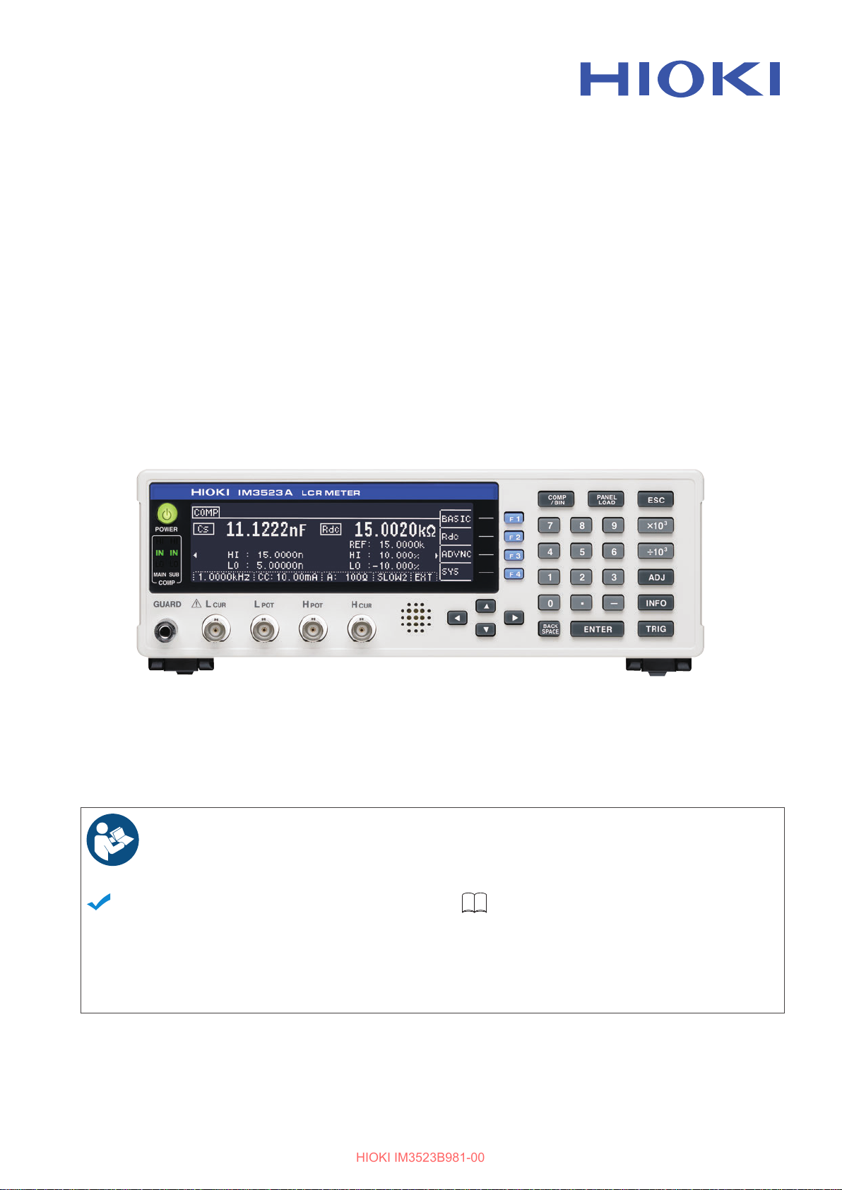
IM3523A
HIOKI IM3523B981-00
LCR METER
Instruction Manual
Dec. 2022 Edition 1
IM3523B981-00 22-12H
Read carefully before use.
Keep for future reference.
When using the instrument for the rst
time
Safety Information
Names and Functions of Parts
Measurement Preparations
p.4 Maintenance and Service
p.10 Error Display
p.21
Troubleshooting
p.209
p.216
EN
[600641400]
Page 2

HIOKI IM3523B981-00
Page 3
Contents
Introduction.....................................................1
HIOKI IM3523B981-00
Verifying Package Contents........................... 2
Options...........................................................3
Safety Information ..........................................4
Safety Symbols ...........................................4
Symbols for Various Standards ..................4
Notation ......................................................5
Measurement categories ............................5
Operating Precautions....................................6
Preliminary Checks .....................................6
Instrument Installation .................................6
Shipping precautions ..................................7
Handling the Instrument ..............................7
Handling the LCR Application Disk .............7
Chapter 1 Overview 9
1.1 Product Overview and Features ..........9
1.2 Names and Functions of Parts ........... 10
1.3 Screen Organization and Operation ..12
1.3.1 Initial Screen ...................................12
1.3.2 Selecting the Measurement Mode ..13
1.3.3 LCR Mode .......................................14
1.3.4 Continuous Measurement Mode ..... 17
1.3.5 System Settings Screen .................. 18
1.3.6 Comparator/BIN Settings Screen .... 19
1.3.7 Panel Load screen .......................... 19
1.3.8 Compensation Settings Screen ....... 19
1.3.9 Information Screen .......................... 20
Chapter 2 Measurement
Preparations 21
2.1 Preparation Flowchart ........................21
2.2 Pre-Operation Inspection ................... 22
2.3 Connecting the Power Cord ...............23
2.4 Connect measurement cables, optional
Hioki probes or test fixture ................. 24
2.5 Turning the Power On and Off ........... 26
i
Contents
Chapter 3 Measurement
Example 27
Chapter 4 LCR Function 29
4.1 About LCR function ............................29
4.2 Setting Basic Settings of Measurement
Conditions ..........................................31
4.2.1 Setting Display Parameters .............31
4.2.2 Setting the Measurement
Frequency ........................................33
4.2.3 Setting the Measurement Signal
Level ................................................37
4.2.4 Limiting the Voltage or Current Applied
to the Sample (Limit Values) ...........41
4.2.5 Setting the Measurement Range .....43
Setting AUTO Ranging ............................ 44
AUTO range limit function ........................ 44
Setting HOLD Ranging ............................ 45
JUDGE SYNC setting .............................. 48
4.2.6 Measuring at User-specified Timing
(Trigger Measurement) ...................50
4.2.7 Setting Measurement Conditions for
Individual Ranges ............................51
List screen layout ..................................... 51
Selecting range settings to change .......... 52
Setting the Measurement speed .............. 53
Displaying Average Values (Average set) 54
Setting a delay before measurement data is
acquired (trigger delay) ............................ 56
Applying the signal to the sample during
measurement only
(Trigger Synchronous Output Function) ... 57
4.3 Setting DC Resistance Measurement 61
4.3.1 Setting the Measurement Range .....62
Setting AUTO Ranging ............................ 63
AUTO range limit function ........................ 63
Setting HOLD Ranging ............................ 64
JUDGE SYNC setting .............................. 66
4.3.2 Setting a Delay Time for DC
Measurement (DC Delay) ................67
4.3.3 Setting a Delay Time for Offset
Measurement (Adjustment Delay) ...69
4.3.4 Setting the Line Frequency ..............70
IM3523B981-00
Page 4
ii
HIOKI IM3523B981-00
Contents
4.3.5 Setting Measurement Conditions for
Individual Ranges ............................71
List screen layout ..................................... 71
Selecting the range setting you wish to
change ..................................................... 72
Setting the measurement speed .............. 73
Displaying Average Values
(Averaging Set) ........................................ 74
Applying settings to all ranges ................. 74
4.4 Judging Measurement Results ...........75
4.4.1 Making Judgments Based on Upper and
Lower Limit Values
(Comparator Measurement Mode) ..76
Setting the Upper or Lower Limit Value as an
Absolute Value (ABS)
(Absolute Value mode) ............................ 78
Setting the Upper or Lower Limit Value as a
Percentage (%) Relative to a
Reference Value (Percentage mode) ...... 79
Setting Upper and Lower Limit Values as (Δ%)
Values Relative to the Offset from the Reference Value (Deviation Percentage Mode) 81
When you want to cancel the comparator
measurement setting: .............................. 82
4.4.2 Classifying Measurement Results
(BIN Measurement Function) .........83
Setting the Upper or Lower Limit Value as an
Absolute Value (ABS)
(Absolute Value mode) ............................ 86
Setting the Upper or Lower Limit Value as a
Percentage (%) Relative to a
Reference Value (Percentage mode) ...... 88
Setting Upper and Lower Limit Values as(Δ%)
Values Relative to the Offset from the Reference Value (Deviation Percentage Mode) 92
When you want to cancel the BIN measure-
ment setting: ............................................ 96
4.5 Setting Application Settings ................97
4.5.1 Saving Measurement Results
(Memory function) ...........................97
4.5.2 Setting the Detection Signal Waveform
Averaging Count
(Waveform Averaging Function) ......99
4.5.3 Setting the Delay Time from the Output
of Comparator and BIN Judgment
Results until Output of EOM (LOW) and
Resetting Judgment Results ..........100
4.5.4 Enabling Trigger Input for during Measurement and Setting the Valid Edge of
Trigger Input ..................................101
4.5.5 Setting the EOM Output Method ...102
4.5.6 Checking Contact Defects and the
Contact State
(Contact Check Function) ..............103
4.5.7 Detecting OPEN during 2-terminal Measurement (Hi-Z Reject Function) ... 105
4.5.8 Turning the LCD Display On and Off
....................................................... 107
4.5.9 Setting the Number of Display Digits
....................................................... 108
4.5.10 Setting Operation Sounds
(Beep Sounds) ............................ 110
Reporting judgment results with beep
operation ................................................ 110
Turning the key tone on and off ............. 111
Changing the beep tone and key tone ... 112
4.5.11 Adjusting the Screen Contrast .... 113
4.5.12 Disabling Key Operation
(Key-lock Function) ..................... 114
Setting the Passcode of the Key-lock .... 116
Canceling key lock mode ....................... 117
4.5.13 Initializing (System Reset) .......... 118
Chapter 5 Continuous Mea-
surement Function
119
5.1 About Continuous Measurement
Function 119
5.1.1 Measurement screen .................... 119
5.1.2 Setting Continuous Measurement . 120
5.2 Configuring Basic Settings
for Continuous Measurement .......... 121
5.3 Performing Continuous Measurement
.......................................................... 122
5.4 Configuring Application Settings for
Continuous Measurement ................ 123
5.4.1 Setting the Display Timing ............ 123
5.4.2 Setting the LCD to ON/ OFF ......... 124
Chapter 6 Error
Compensation 125
6.1 Setting Open Circuit Compensation 125
6.1.1 All Compensation .......................... 127
6.1.2 Spot Compensation ...................... 131
6.2 Short Circuit Compensation ............. 136
6.2.1 All Compensation .......................... 138
6.2.2 Spot Compensation ...................... 140
6.3 Adjusting Values Based on Reference
Values (Load Compensation) .......... 145
Page 5

6.4 Compensating Measurement Cable
HIOKI IM3523B981-00
Errors(Cable Length Compensation) 157
6.5 Converting Values (Scaling) ............158
Chapter 7 Saving and Reading
Panel Information
161
7.1 Saving Measurement Conditions
(Panel Save Function) .....................162
7.2 Reading Measurement Conditions
(Panel Load Function) ...................... 165
7.3 Changing a Panel Name ..................167
7.4 Deleting a Panel ............................... 169
Chapter 8 Setting
the SYSTEM 171
8.1 Setting the Interface .........................171
8.2 Checking the Version of the Instrument
..........................................................172
8.3 Self Checks (Self Diagnosis) ...........173
iii
Contents
Chapter 10 Specifications 195
10.1 General Specifications .....................195
10.2 Measurement Range and Accuracy .200
Example calculation ............................... 204
10.3 About Measurement Times and
Measurement Speed ........................207
Chapter 11 Maintenance
and Service 209
11.1 Inspection, Repair and Cleaning ......209
Inspection and Repair ............................ 209
Replaceable Parts and Operating Lifetimes
................................................................ 209
Transporting the instrument ................... 210
Cleaning ................................................. 210
Disposal ................................................. 210
11.2 Troubleshooting ................................211
Before returning for repair ...................... 211
When no apparent cause can be established
................................................................ 214
Full Reset Procedure ............................. 215
11.3 Error Display .....................................216
Chapter 9 External Control 177
9.1 External Input/Output Connector and
Signals .............................................177
Connector Type and Signal pin assignments
.................................................................178
Signal Descriptions .................................182
9.2 Timing Chart ....................................184
9.2.1 LCR Measurement ........................184
9.2.2 Continuous Measurement .............187
9.3 Internal Circuitry ...............................188
Electrical Specifications ..........................189
Connection Examples .............................190
9.4 External I/O Settings ........................ 191
Setting Delay Time from Output of
Comparator and BIN Judgment Results until
Output of EOM (LOW) ............................191
Setting Reset of Judgment Results ........191
Enabling Trigger Input for during
Measurement ..........................................191
Setting Valid Edge of Trigger Input .........191
9.5 External Control Q&A ....................... 192
9.6 Measurement Using a Computer ..... 193
Appendix A1
Appendix1 Measurement Parameters and
Calculation formula .................. A 1
Appendix2 Measurement of High Impedance
Components............................. A 3
Appendix3 Measuring In-circuit Elements.. A 4
Appendix4 Countermeasures Against
Incorporation of External Noise A 5
Appendix4.1Countermeasures Against
Incorporation of Noise from the
Power Line ........................ A 5
Appendix4.2Countermeasures Against
Noise from the measurement
Cables .............................. A 6
Appendix5 Supplying DC Bias ................... A 7
Appendix5.1How to Supply a DC Bias
Voltage ............................. A 7
Appendix5.2How to Supply a DC Bias
Current .............................. A 8
Appendix6 The Residual Charge Protection
Function ................................... A 9
Page 6

iv
HIOKI IM3523B981-00
Contents
Appendix7 Series Equivalent Circuit Mode and
Parallel Equivalent Circuit Mode
............................................... A 10
Appendix8 Open Circuit Compensation and
Short Circuit Compensation ... A 11
Appendix9 Rack Mounting ....................... A 13
Appendix10 Dimensional Diagram ........... A 15
Appendix11 Initial Settings Table ............. A 16
Index Index i
Page 7
Introduction
HIOKI IM3523B981-00
Introduction
Thank you for choosing the HIOKI Model IM3523A LCR Meter. To ensure your ability to get the most out
of this instrument over the long term, please read this manual carefully and keep it available for future reference.
The latest edition of the instruction manual
The contents of this manual are subject to change, for example as a result of product improvements or changes to specifications.
The latest edition can be downloaded from Hioki’s website.
https://www.hioki.com/global/support/download/
Product registration
Register your product in order to receive important product information.
https://www.hioki.com/global/support/myhioki/registration/
1
Refer to the following instruction manuals
Please review the separate “Operating Precautions” before using the instrument.
Name of the
instruction m
Instruction Manual
(this manual)
Communication
Instruction Manual
Startup Guide Includes information for using the instrument safely,
Operating Precautions Information for using the instrument safely. Hard copy
anual
Includes overview of the instrument, operation
m
ethods, function descriptions, and specifications.
Includes information related
ment using its communications interface.
basic ope
vant information).
in accordance with your application.
Description Format
to controlling the instru-
ration methods, specifications (selected rele-
PDF file
(included on CD)
PDF file
(included on CD)
Hard copy
Page 8

2
IM3523A LCR Meter ............................. 1
LCR Application Disk .............................1
(Instruction Manual [PDF format], Communication
Instruction Manual [(PDF format], explanation of
communications commands, USB driver, sample
application)
The latest version can be downloaded
from Hioki’s website.
Startup Guide ........................................1
Operating Precautions (0990A905) .......1
Power Cord (2-line + ground) (p. 23) .... 1
Confirm that these contents are provided.
HIOKI IM3523B981-00
Verifying Package Contents
Verifying Package Contents
When you receive the instrument, inspect it carefully to ensure that no damage occurred during shipping. In particular,
check the accessories, panel switches, and connectors. If damage is evident, or if it fails to operate
according to the specifications, contact your dealer or Hioki representative.
• Probes, fixture are not supplied with the unit as standard equipment. You should order
them separately, according to requirements.
• The instrument ships from the factory configured as described in "Appendix11 Initial Set-
tings Table"(p. A16).
Precautions when transporting the instrument
Use the original packing materials when transporting the instrument, if possible.
See "Transporting the instrument" (p. 210)
Page 9
3
Measurable range: DC to 200 kHz
Maximum voltage:
±42 V peak (AC+DC)
Maximum current:
±1 A peak (AC+DC)
Measurable terminal diameter: 0.3 mm to 5 mm
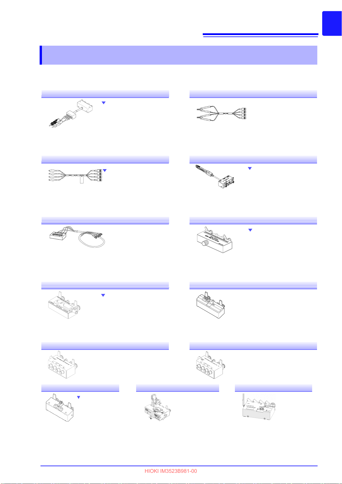
L2000 4-Terminal Probe
Alligator-clip-type measurement probes. These generalpurpose dual-electrode clips fit
a wide range of conductor
thicknesses.
Measurable range: DC to 8 MHz
Maximum voltage: ±42 V peak (AC+DC)
Maximum current: ±1 A peak (AC+DC)
Measurable terminal diameter: 0.3 mm to 5 mm
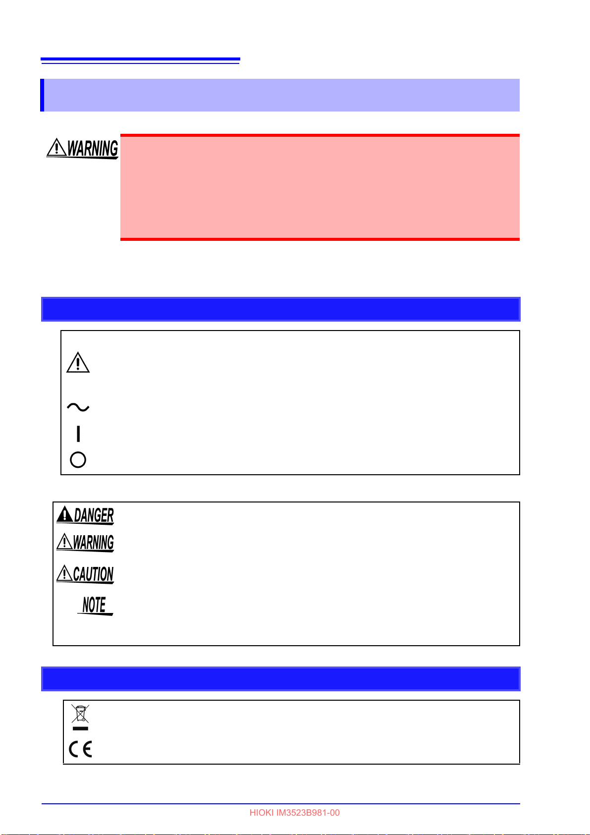
9140-10 4-Terminal Probe
Measurable range: DC to 8 MHz
Maximum applied voltage:
±42 V peak (AC+DC)
Maximum applied current:
±1 A peak (AC+DC)
Electrode tip spacing: 0.3 mm to 6 mm
Measurable range: DC to 200 kHz
Maximum voltage:
±40 V DC (42 V peak [Measurement signal + bias voltage])
Maximum current: 1 A peak (Measurement signal + bias current)
Measurable terminal diameter: 0.3 mm to 2 mm
Rubber-sheathed alligator clip
type
9500-10 4-Terminal Probe
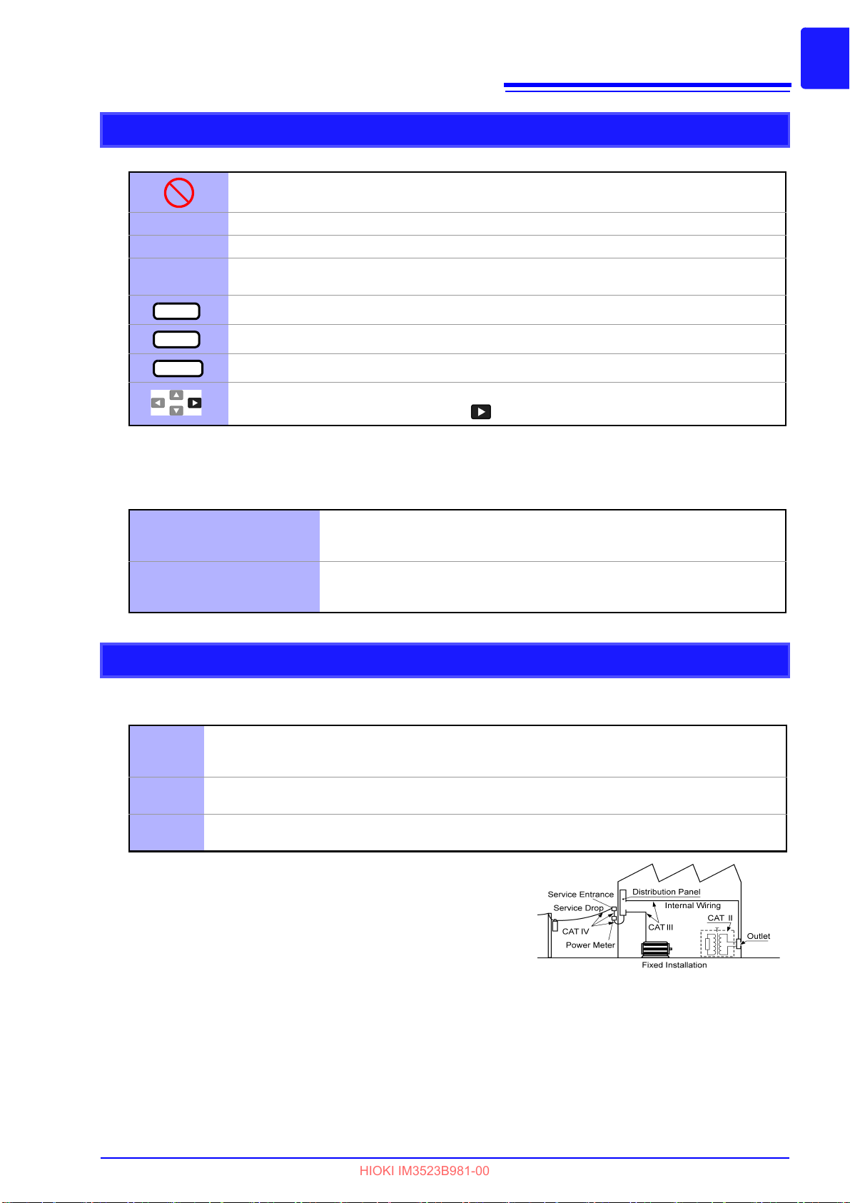
Pincher type
L2001 Pincher Probe
9261-10 Test Fixture
Measurable range: 42 Hz to 8 MHz
Maximum applied voltage: ±40 V DC
Test sample dimensions: Lead diameter of 0.3 mm to 2 mm
Lead pitch of 5 mm or more
This fixture is for measuring
lead components. (residual
resistance of 10 mΩ or less
after zero adjustment)
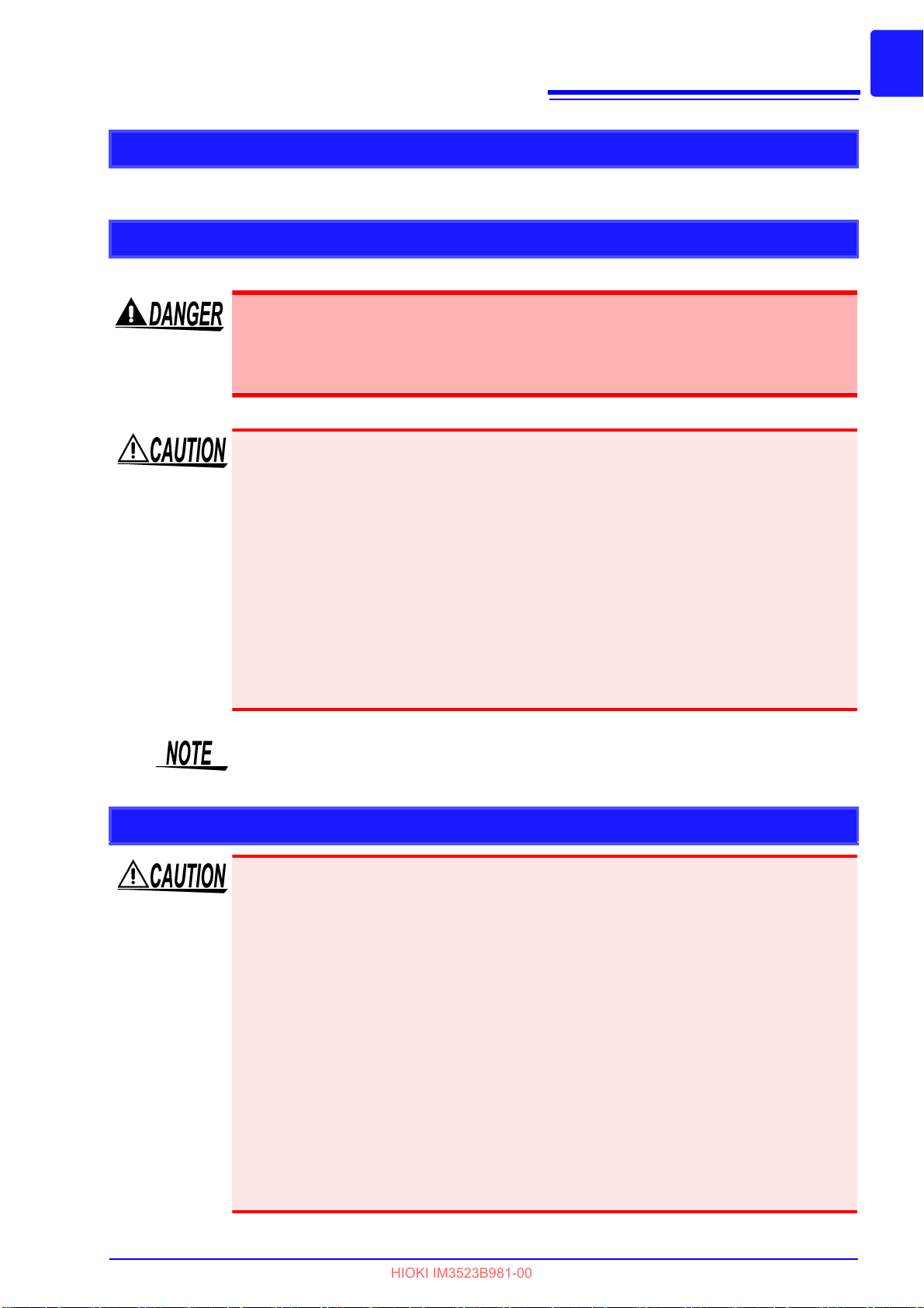
9262 Test Fixture
Measurable range: DC to 8 MHz
Maximum applied voltage:
±40 V DC
Measurable terminal diameter: 0.3 mm to 1.5 mm
9263 SMD Test Fixture
This fixture is for measuring chip
components. (residual resistance
of 10 mΩ or less after zero adjustment)
Measurable range: DC to 120 MHz
Maximum applied voltage: ±40 V DC
Test sample width of 3.5 ±0.5 mm
Measurable range: DC to 8 MHz
Maximum applied voltage: ±40 V DC
Test sample dimensions: Test sample width of 1 mm to 10 mm
9677 SMD Test Fixture
9268-10 DC Bias Voltage Unit
Measurable range: 40 Hz to 2 MHz
Maximum applied current: 2 A DC
Measurable range: 40 Hz to 8 MHz
Maximum applied voltage:
±40 V DC
9269-10 DC Bias Current Unit
This fixture is for the
lower electrode.
Measurable range: DC to 120 MHz
Maximum applied voltage: ±40 V DC
Test sample dimensions: Test sample width of
1 mm to 4 mm
Test sample height of 1.5 mm or less
9699 SMD Test Fixture
Measurable range: DC to 8 MHz
Maximum applied voltage: ±42 V peak
(AC+DC)
Maximum applied current:
±0.15 A rms (±0.15 A DC)
Measurement test sample dimensions:
0.4 × 0.2 mm, 0.6 × 0.3 mm, 1.0 × 0.5 mm
IM9100 SMD Test Fixture
Measurable range: DC to 1 MHz
Maximum applied voltage: ±42 V peak
(AC+DC)
Maximum applied current:
±0.15 A rms (±0.15 A DC)
Measurement test sample dimensions:
0.25 ±20% × 0.125 ±10% × 0.125 ±10%mm
IM9110 SMD Test Fixture
HIOKI IM3523B981-00
Options
Options
The following options are available for the instrument. Contact your authorized Hioki distributor or reseller
when ordering. The options are subject to change. Visit our website for updated information.
Page 10
4
HIOKI IM3523B981-00
Safety Information
Safety Information
This instrument is designed to comply with IEC 61010 Safety Standards, and has
been thoroughly tested for safety prior to shipment. However, mishandling during
use could result in injury or death, as well as damage to the instrument. Using the
instrument in a way not described in this manual may negate the provided safety features.
Be certain that you understand the instructions and precautions in the manual before
e. We disclaim any responsibility for accidents or injuries not resulting directly
us
from instrument defects.
This manual contains information and warnings essential for safe operation of the instrument and for
maintaining it in safe operating condition. Before using it, be sure to carefully read the following safety
precautions.
Safety Symbols
Indicates the presence of a potential hazard. For more information about locations where this
symbol appears on instrument components, see the “Operating Precutions” section (p. 6),
warning messages listed at the beg
document entitled “Operating Precautions.”
Indicates AC (Alternating Current).
Indicates the ON side of the power switch.
Indicates the OFF side of the power switch.
The following symbols in this man
Indicates an imminently hazardous situation that, if not avoided, w
serious injury.
Indicates a potentially hazardous situation that,
serious injury.
Indicates a potentially hazardous situation that could result in minor or moderate injury
r potential risks of damage to the supported product (or to other property) if not
o
avoided.
Indicates advisory items re
IMPORTANT
Indicates information or content that is particularly important from the standpoint of
operating or maintaining the instrument.
inning of operating instructions, and the accompanying
ual indicate the relative importance of cautions and warnings.
ill result in death or
if not avoided, could result in death or
lated to performance or correct operation of the instrument.
Symbols for Various Standards
Indicates that the product is subject to the Waste Electrical and Electronic Equipment
(WEEE) Directive in EU member nations.
Dispose of the product in accordance with local regulations.
This symbol indicates that the pr
oduct conforms to regulations set out by the EU Directive.
Page 11
Notation
DIGIT
10KEY
ENTER
HIOKI IM3523B981-00
Symbols in this manual
Indicates a prohibited action.
5
Safety Information
(p. )
* Indicates that descriptive information is provided below.
[ ]
Indicates the location of reference information.
Menus, Pages, Setting items, dialogs, buttons in a dialog, and other names on the
screen and the keys are indicated in brackets.
Indicates that digits may be entered. (p. 35)
Indicates that values may be entered using the numeric keypad. (p. 33)
Indicates that the same operation can be performed by pressing the ENTER key.
The cursor key to be used is shown in black, while unused cursor keys are shown in
gray. (In the example to the left, the key is to be used.)
Accuracy labeling
The instrument’s accuracy is expressed using a combination of the formats shown below.
• By defining limit values for errors using the same units as measured values.
• By defining limit values for errors as a percentage of the reading and a percentage of the setting.
Indicates the value displayed by the instrument. Limit values for reading
Reading (display value):
Setting (set value)
errors are expressed as a percentage of the reading (“% of reading” or
“% rdg”).
Indicates the set value, such as voltage and current, that the instrument
as been configured to output. Limit values for setting errors are
h
expressed as a percentage of the setting (“% of setting”).
Measurement categories
To ensure safe operation of measurement instruments,
ous electrical environments, categorized as CAT II to CA
CAT II
CAT III
CAT IV
Using a measurement instrument in an environment designated
with a hig
ment is rated could result in a severe accident, and must be
efully avoided.Using a measurement instrument in an envi-
car
ronment designated with a higher numbered category than that
for which
dent, and must be carefully avoided.
Primary electrical circuits in equipment connected to an AC electrical outlet by a power
cord (portable tools, household appliances, etc.)
CAT II covers directly measuring electrical outlet receptacles.
Primary electrical circuits of heavy equipment (fixed installations) connected directly to the
distribution panel, and feeders from the distribution panel to outlets.
The circuit from the service drop to the service entrance, and to the power meter and primary overcurrent protection device (distribution panel).
her-numbered category than that for which the instru-
the instrument is rated could result in a severe acci-
IEC 61010 establishes safety standards for vari-
T IV, and called measurement categories.
Page 12

6
50 mm or more
10 mm or more50 mm or more
HIOKI IM3523B981-00
Operating Precautions
Operating Precautions
• Follow these precautions to ensure safe operation and to obtain the full benefits of the various functions.
• Use of the instrument should confirm not only to its specifications, bu
accessories, options, and other equipment in use.
Preliminary Checks
t also to the specifications of all
Before using the instrument the first time, verify th
at it operates normally to ensure that the no damage
occurred during storage or shipping. If you find any damage, contact your dealer or Hioki representative.
Before using the instrument, make sure that the insulation on the voltage cords is
undamaged and that no bare conductors are improperly exposed. Using the instrument in such conditions could cause an electric shock, so contact your dealer or
Hioki representative for replacements.
Instrument Installation
Avoid the following locations that could cause an accident or damage to the instrument.
Exposed to direct sunlight
Exposed to high temperature
Exposed to water, oil, other
chemicals,
Exposed to high humidity or
condensation
Exposed to high levels of particulate dust
or solvents
In the presence of corrosive or explosive gases
Exposed to strong electromagnetic
fields
Near electromagnetic radiators
Near induction heating
systems (e.g., high-frequency
induction heating systems and IH
cooking utensils)
Subject to vibration
• The instrument should be operated only
with the bottom side downwards.
• The instrument must not be placed on an unstable table or tilted surface.
• Vents must not be obstructed.
• The instrument can be used with the stand.(p. 11)
It can also be rack-mounted.(p.A13)
• If mounting the instrument in a confined space such as a
rack, ensure that the ambient temperature remains
within the range specified in the product specifications, for example by using forced-air cooling.
Page 13
Operating Precautions
HIOKI IM3523B981-00
Shipping precautions
Hioki disclaims responsibility for any direct or indirect damages that may occur when this instrument has
been combined with other devices by a systems integrator prior to sale, or when it is resold.
Handling the Instrument
• To avoid electric shock, do not remove the instrument's case. The internal compo-
nents of the instrument carry high voltages and may become very hot during operation.
• Do not allow the instrument to get wet, and do not take measurements with wet
hands. This may cause an electric shock.
• If the instrument exhibits abnormal operation or display during use, review the informa-
tion in "Troubleshooting" (p. 211) and "Error Display" (p. 216) before contacting your
dealer or Hioki representative.
• Do not connect charged capacitors to measurement terminals or input voltages or cur-
rents from an external source. Doing so may damage the instrument.
• This instrument is not designed to be entirely water- or dust-proof. Do not use it in an
especially dusty environment, nor where it might be splashed with liquid. This may cause
damage.
• To avoid damage to the instrument, protect it from physical shock when transporting and
handling. Be especially careful to avoid physical shock from dropping.
• Do not apply heavy downward pressure with the stand extended. The stand could be
damaged.
• After use, always turn OFF the power.
7
This instrument complies with EN 61326 Class A. This instrument may cause interference if used in
residential areas. Such use must be avoided unless the user takes special measures to reduce electromagnetic emissions to prevent interference to the reception of radio and television broadcasts.
Handling the LCR Application Disk
• Always hold the disc by the edges, so as not to make fingerprints on the disc or scratch
the printing.
• Never touch the recorded side of the disc. Do not place the disc directly on anything
hard.
• Do not wet the disc with volatile alcohol or water, as there is a possibility of the label print-
ing disappearing.
• To write on the disc label surface, use a spirit-based felt pen. Do not use a ball-point pen
or hard-tipped pen, because there is a danger of scratching the surface and corrupting
the data. Do not use adhesive labels.
• Do not expose the disc directly to the sun's rays, or keep it in conditions of high tempera-
ture or humidity, as there is a danger of warping, with consequent loss of data.
• To remove dirt, dust, or fingerprints from the disc, wipe with a dry cloth, or use a CD
cleaner. Always wipe from the inside to the outside, and do no wipe with circular movements. Never use abrasives or solvent cleaners.
• Hioki shall not be held liable for any problems with a computer system that arises from
the use of this LCR Application Disk, or for any problem related to the purchase of a Hioki
product.
Page 14

8
HIOKI IM3523B981-00
Operating Precautions
Page 15
9
BIN function(p.83)
Capable of easily ranking up to
10 samples based on measurement values.
Wide range of measurement conditions(p.31)
Capable of measurement under a wide range of measurement conditions: measurement frequencies from 1 mHz to
200 kHz and measurement signal levels from 5 mV to 5 V.
Comparator function(p.76)
Capable of making HI/IN/LO
pass/fail judgments based on
measurement values for two
parameters.
Simple production
line setup changes
Automatically sets the optimal range according to
comparator or BIN judgment standards. Because
the IM3523A also lets you
set measurement conditions separately for each
range, it is possible to
automatically set the optimal measurement conditions in response to range
changes.
Continuous measurement function(p.119)
Capable of performing continuous measurement using previously stored
measurement conditions. This function makes it possible to generate pass/
fail judgments using different sets of measurement conditions. (For example, the instrument can perform C-D measurement at 120 Hz followed by Rs
measurement at 100 kHz.)
Various interfaces supported
Supports the optimal external I/O (handler
interfaces) for production lines: USB and
LAN.
Capable of highspeed measurement
High-speed measurement
is possible. The IM3523A
can perform measurements
at speeds of up to 2 ms (typical values).
HIOKI IM3523B981-00
1.1 Product Overview and Features
1
Overview Chapter 1
1.1 Product Overview and Features
The HIOKI IM3523A LCR Meter is an impedance measuring instrument that features high-speed, highprecision operation.
With measurement frequencies of 40 Hz to 200 kHz and
instrument allows you to configure a broad range of measurement conditions. Additionally, the ability to
perform tests using different measurement conditions with a single instrument while changing setup profiles easily makes the IM3523A well suited for use on production lines.
measurement signal levels of 5 mV to 5 V, the
Chapter 1 Overview
Page 16

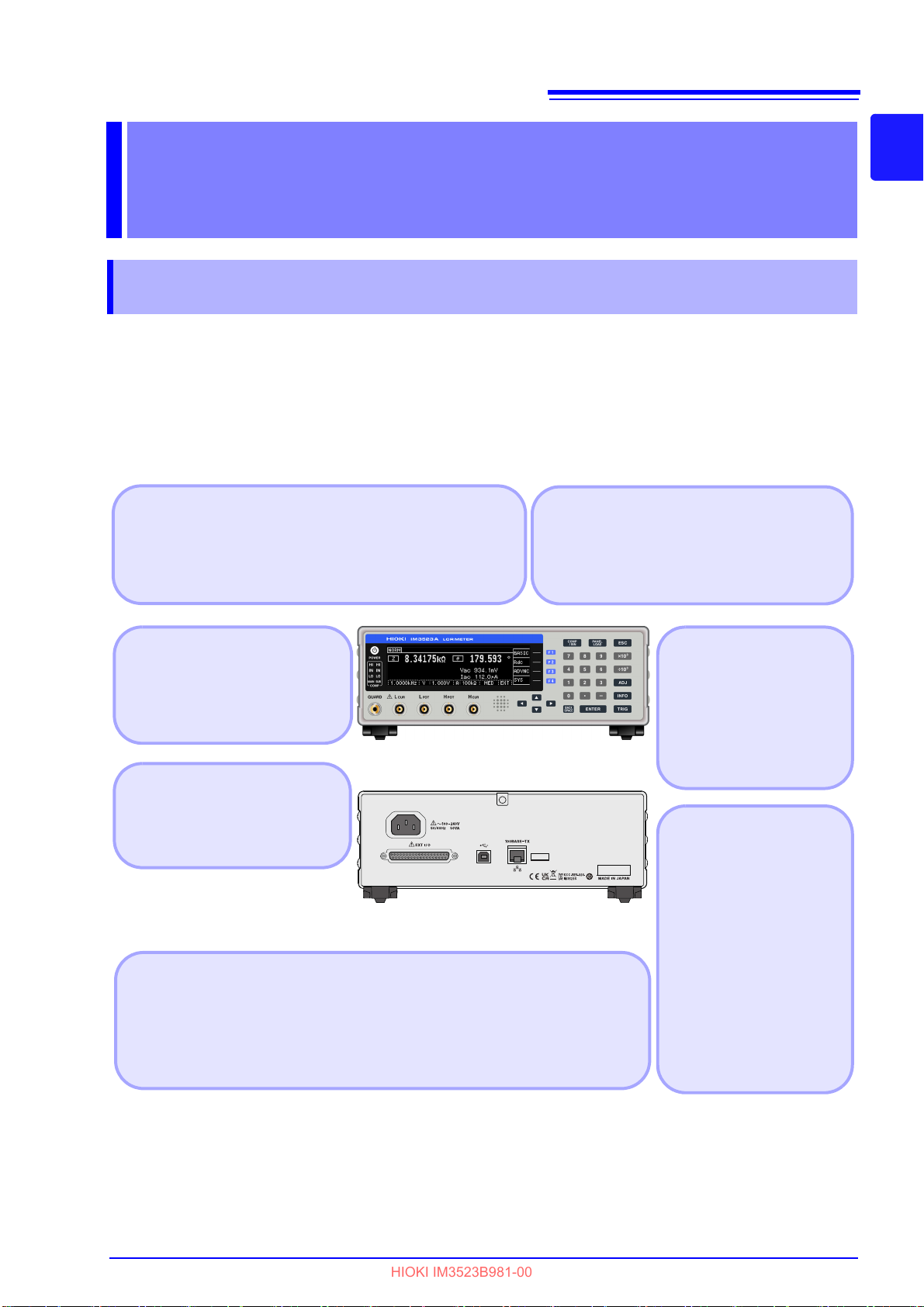
10
Display Screen(p.12)
Monochrome graphical LCD
Displays the Measurement
screen, Basic Settings screen,
and Advanced Settings
screen.
COMP/BIN Key(p.75)
Panel Load Key(p.165)
When the comparator/BIN function
is enabled, displays the Comparator/BIN Settings screen.
Loads measurement conditions
saved with the panel save function.
Power Switch(p.26)
• Unlit : power off
(when no power supplied)
• Red light : power off
(while power is supplied)
• Green light : power on
F keys
Cursor keys
Selects the corresponding
item on the right side of the
display.
Selects items on the screen.
Measurement Terminals
Connect measurement cables
or a fixture.
(H
CUR
jack, H
POT
jack, L
POT
jack, L
CUR
jack, GUARD jack)
Audible Alarm
(beeper)
Entering numerical values(p.12)
Enter a numerical value.
(we call these the “tenkeys”)
Adds a minus sign to the value.
Switches units.
Deletes the value in the
selected field.
Accepts the value and settings.
Cancels the measurement
condition settings for each
range and the comparator/BIN
settings, and then returns to
the screen that was displayed
before you began configuring
settings.
ADJ Key(p.125)
INFO Key(p.20)
TRIG Key(p.50)
Lets you configure and use
compensation functions and
scaling.
Lets you check previously configured measurement conditions.
Performs trigger measurement under the conditions for
which the external trigger has
been configured.
Front
COMP indicator
LEDs
Displays the measurement value judgment
results for the main and
sub parameters.
Comparator
measurement
See (p.76)
BIN measurement
See (p.83)
Panel
This instrument can be rack mounted.
See "Appendix9 Rack Mounting"(p. A13)
HIOKI IM3523B981-00
1.2 Names and Functions of Parts
1.2 Names and Functions of Parts
Page 17
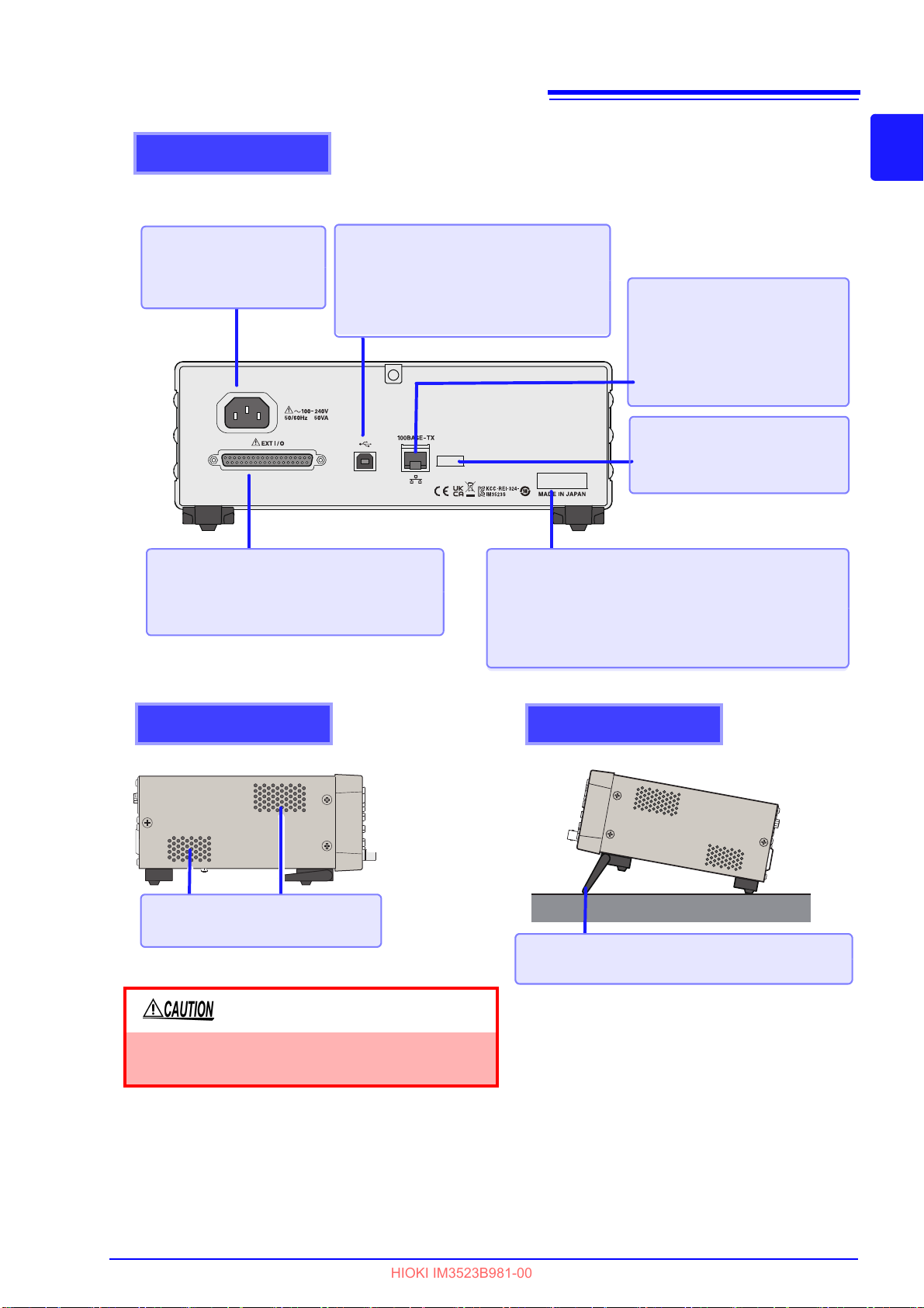
EXT I/O connector
Lets you connect a PLC or I/O board so
that you can start measurement and
acquire judgment results. (p.177)
Rear
Power inlet
Connect the power cord.
(p.23)
LAN connector
Lets you control the instrument
from a computer via a LAN
(socket communications).
See Communication Instruction
Manual (LCR Application
Disk)
Rear USB connector
Connect a computer to control the
instrument using communications
commands.
See
Communication Instruction Manual (LCR
Application Disk)
LAN MAC address
See Communication Instruction
Manual (LCR Application
Disk)
When using the stand
Extend the stand until it clicks into place.
Make sure to extend both legs of the stand.
Collapsing the stand
Fold in the stand until it clicks into place.
Do not apply heavy downward pressure with the
stand extended. The stand could be damaged.
Left
Right
Stand
Lets you incline the instrument for easy viewing.
Vents
Keep clear of obstructions. (p.6)
Manufacturer’s serial number
The serial number consists of nine digits. The first
two digits indicate the year of manufacture, while
the second two digits indicate the month of manufacture. Do not remove this sticker as the number
is important.
HIOKI IM3523B981-00
11
1.2 Names and Functions of Parts
1
Chapter 1 Overview
Page 18
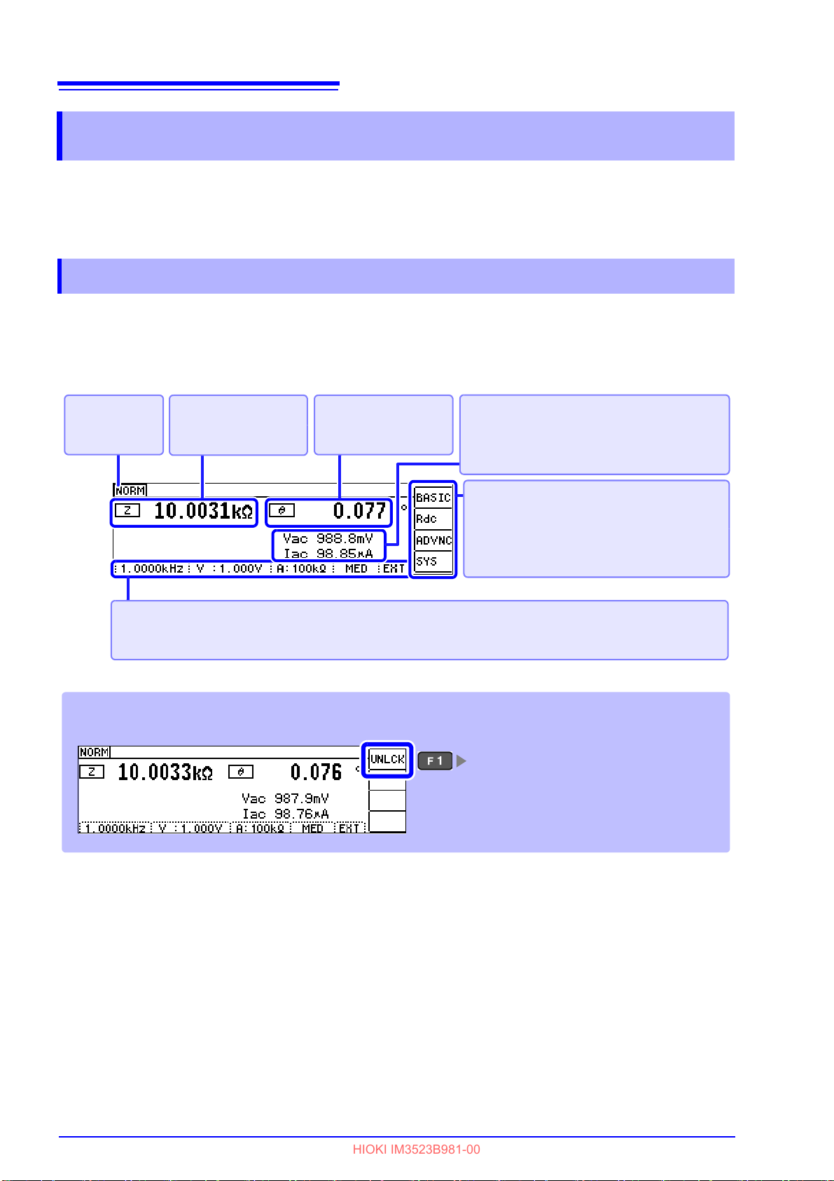
12
Indicates the
measurement
mode.
Indicates some of the measurement conditions.
(From the left) Frequency, measurement signal level, measurement range, measurement speed,
trigger measurement.
Menu keys
[BASIC] :Configures basic settings.
[Rdc] :Configures DC resistance
measurement settings.
[ADVNC] :Configures application settings.
[SYS] :Configures system settings.
Indicates the sub
parameter and
measurement value.
Monitor values
V
ac,Vdc
:Voltage across the terminals of
the sample.
I
ac
, I
dc
:Current passing through the
sample.
Indicates the main
parameter and
measurement value.
Key lock screen
The Pass Code Entry screen will be displayed.
See "Canceling key lock mode" (p. 117)
HIOKI IM3523B981-00
1.3 Screen Organization and Operation
1.3 Screen Organization and Operation
The instrument has two general display screen types: Measurement and Settings.
Refer to "11.3 Error Display" (p. 216) for error displays.
The screen examples in this guide appear
instrument screens can actually be displayed only as white characters on black background.
1.3.1 Initial Screen
reversed (black on white) for best visibility. However, the
The initial screen, which is the first scr
form measurement while checking measurement conditions.
display will reflect the measurement mode that was in use when the power was turned off.
een displayed when you turn on the instrument, allows you to per-
When the instrument is turned back on, the
Page 19
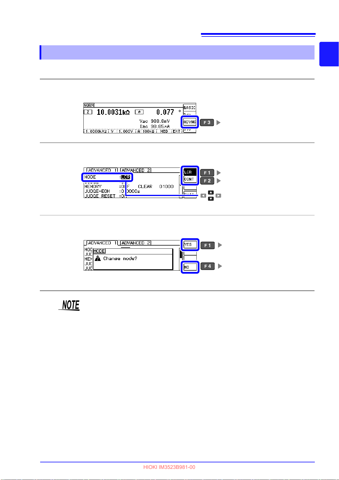
13
Displays the Advanced Settings screen.
Select
Selects continuous measurement mode.
(p.121)
Selects LCR mode.
Changes the measurement mode to
the selected mode.
Returns to the Advanced Settings
screen without changing
the measurement mode.
HIOKI IM3523B981-00
1.3 Screen Organization and Operation
1.3.2 Selecting the Measurement Mode
This section describes how to select the measurement mode.
Open the Advanced Settings screen.
1
Select the [MODE]
.
2
1
Chapter 1 Overview
3
Set the mode.
After changing the measurement mode, check all settings (including compensation) before performing
measurement.
Page 20
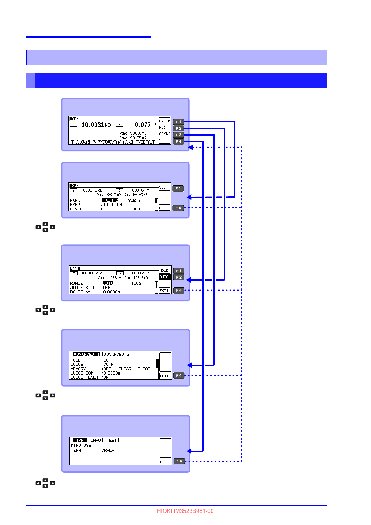
14
Rdc Settings Screen (p.15)
To the settings screen for the selected basic setting
Measurement Screen (p.29)
Basic Settings Screen (p.15)
Return to Previous Screen
Return to Previous Screen
To the settings screen for the selected Rdc setting
Advanced Settings Screen (p.16)
To the settings screen for the selected advanced setting
System Settings Screen (p.18)
To the settings screen for the selected system setting
Return to Previous Screen
Return to Previous Screen
HIOKI IM3523B981-00
1.3 Screen Organization and Operation
1.3.3 LCR Mode
Screen Organization
Page 21
15
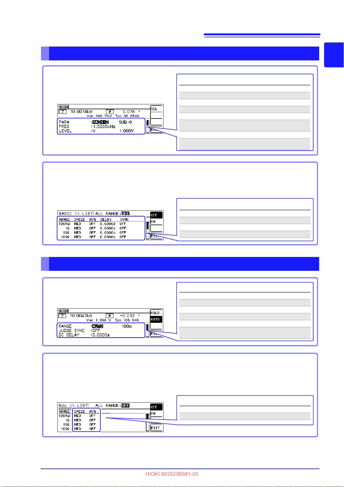
Basic Settings Screen
Settings
PAR A Measurement parameter setting (p.31)
FREQ Measurement frequency setting (p.33)
LEVEL Measurement signal level setting (p.37)
LIMIT Voltage and current limit settings (p.41)
RANGE Measurement range setting (p.43)
JUDGE
SYNC
Judgment synchronization setting (p.48)
TRIG Trigger setting (p.50)
LIST Setting of measurement conditions for the respec-
tive ranges (p.51)
This screen allows you to configure basic
settings for the measurement conditions.
LIST Settings screen
Settings
SPEED Measurement speed setting (p.53)
AVG Average setting (p.54)
DELAY Trigger delay setting (p.56)
SYNC Trigger synchronization output setting (p.57)
This screen is displayed when you select [LIST] on the Basic Settings screen.
It allows you to configure measurement conditions for each range.
Settings
RANGE Measurement range setting (p.62)
JUDGE SYNC Judgment synchronization setting (p.66)
DC DELAY DC delay setting (p.67)
ADJ DELAY Adjustment delay setting (p.69)
LINE FREQ Line frequency setting (p.70)
LIST
Setting of measurement conditions for the
respective ranges (p.71)
This screen allows you to configure measurement
conditions for DC resistance measurement.
LIST Settings screen
Settings
SPEED Measurement speed setting (p.73)
AVG Average setting (p.74)
This screen is displayed when you select [LIST] on the Rdc Settings screen.
It allows you to configure measurement conditions for each range.
HIOKI IM3523B981-00
1.3 Screen Organization and Operation
Basic Settings Screen
1
Chapter 1 Overview
Rdc (DC resistance measurement) Settings screen
Page 22
16
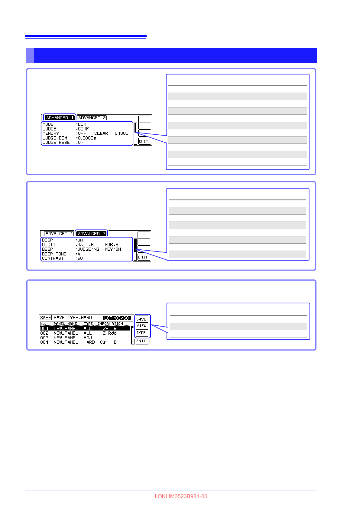
Advanced 1 Settings Screen
Settings
MODE Measurement mode setting (p.13)
JUDGE Measurement result judgment setting (p.75)
MEMORY Save settings of measurement results (p.97)
JUDGE-EOM JUDGE-EOM delay time setting (p.100)
JUDGE RESET JUDGE-EOM reset setting (p.100)
TRIG ENABLE IO trigger setting (p.101)
TRIG EDGE IO trigger valid edge setting (p.101)
EOM MODE EOM output method setting (p.102)
EOM-ON-TIME EOM output time setting (p.102)
CONTACT Contact check function setting (p.103)
Hi Z Hi-Z reject function setting (p.105)
This screen is used to configure LCR mode
application settings.
Advanced 2 Settings Screen
This screen is used to configure LCR mode
application settings.
Settings
DISP LCD settings (p.107)
DIGIT Number of display digits setting (p.108)
BEEP Beep enable/disable setting (p.110)
BEEP TONE Beep tone setting (p.112)
CONTRAST Screen contrast setting (p.113)
KEYLOCK Key-lock setting (p.114)
PANEL SAVE Panel save (p.162)
RESET System reset (p.118)
Settings
SAVE Panel save (p.163)
VIEW Panel information display (p.164)
TYPE Panel save type setting (p.162)
This screen is used to configure continuous
measurement mode application settings.
Panel Save Screen
HIOKI IM3523B981-00
1.3 Screen Organization and Operation
Advanced Settings Screen
Page 23

17
Advanced Settings Screen (p.123)
Select the continuous measurement target panel.
Measurement Screen (p.119)
Basic Settings Screen (p.121)
Return to Previous Screen
Return to Previous Screen
To the settings screen for the selected advanced setting
Settings
OFF Turns off continuous measurement
ON Turns on continuous measurement
INFO Panel information display
This screen allows you to check continuous measurement
settings and saved panel information. (p.121)
This screen is used to configure continuous
measurement mode application settings. (p.123)
Settings
MODE Measurement mode setting (p.120)
DRAW Display timing setting (p.123)
DISP LCD setting (p.124)
HIOKI IM3523B981-00
1.3 Screen Organization and Operation
1.3.4 Continuous Measurement Mode
Screen Organization
1
Chapter 1 Overview
Basic Settings Screen
Advanced Settings Screen
Page 24
18
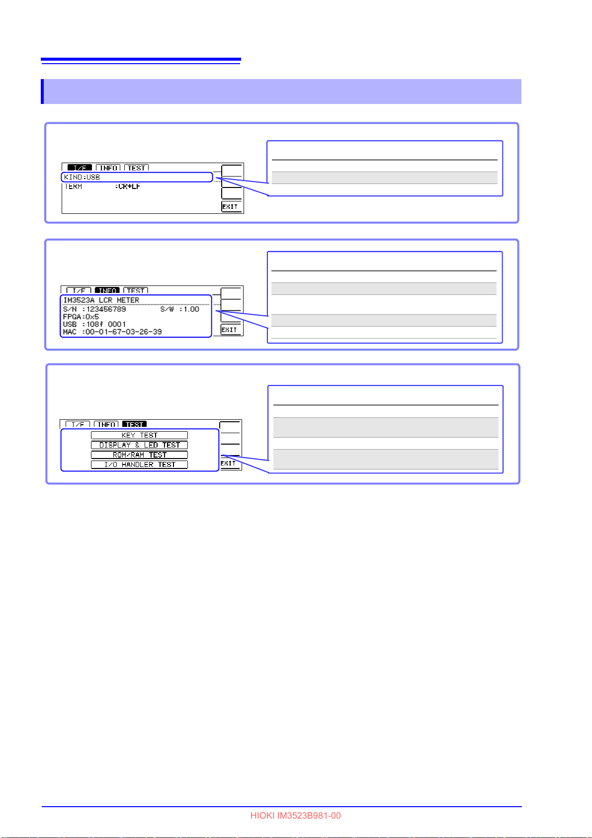
Settings
USB USB Setting (p.171)
LAN LAN Setting (p.171)
This screen is used to set
the interface type.
Check the version of the instrument
Settings
S/N Serial No. (p.172)
FPGA FPGA Version (p.172)
USB
USB ID
(Vendor ID, product ID) (p.172)
MAC MAC address (p.172)
S/W Software Version (p.172)
Settings
KEY TEST Performs a key test (p.173)
DISPLAY &
LED TEST
Performs a screen display test (p.174)
ROM/RAM TEST Performs a ROM/RAM test (p.175)
I/O HANDLER
TEST
Performs an I/O test (p.176)
Self Check
HIOKI IM3523B981-00
1.3 Screen Organization and Operation
1.3.5 System Settings Screen
Page 25
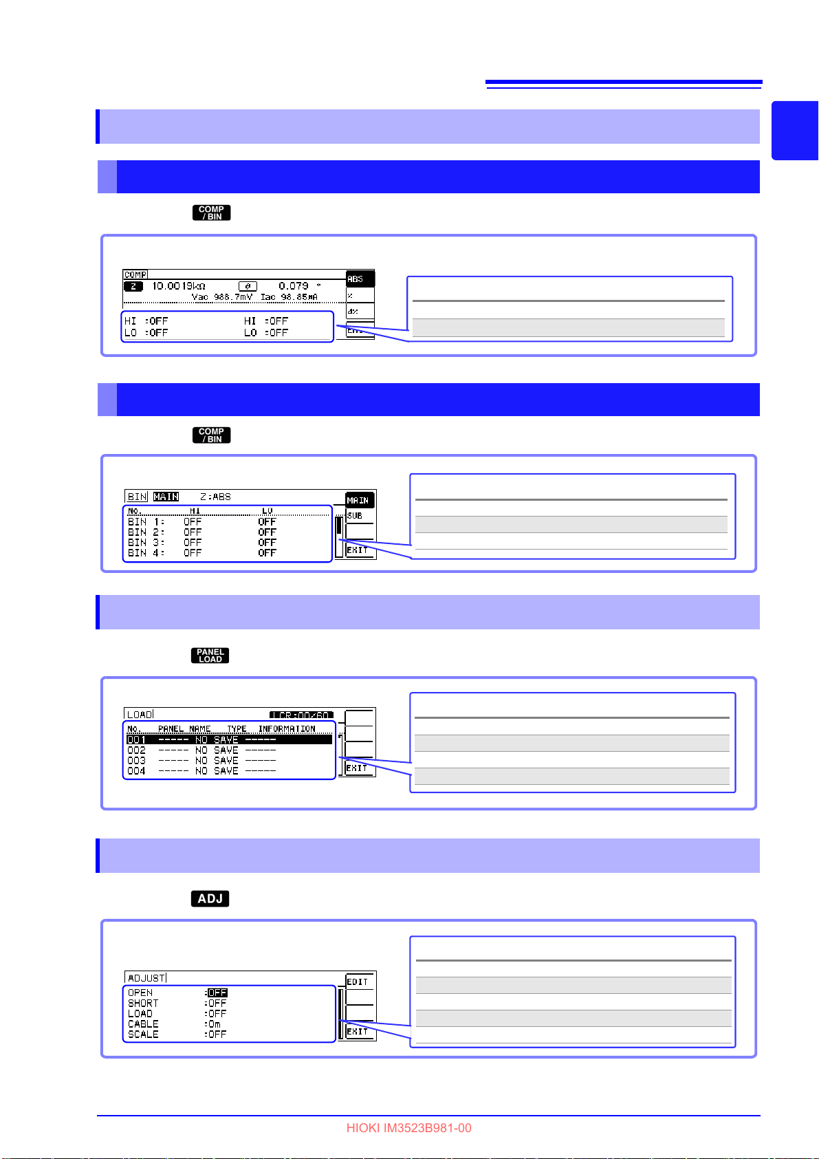
19
Settings
HI Upper Limit Value Setting (p.76)
LO Lower Limit Value Setting (p.76)
Settings
No. BIN number (p.83)
HI Upper Limit Value Setting (p.83)
LO Lower Limit Value Setting (p.83)
Settings
No. Panel No. (p.165)
PANEL NAME Panel name (p.165)
TYPE Save type (p.165)
INFORMATION Saved information (p.165)
Settings
OPEN Open circuit compensation setting (p.125)
SHORT Short circuit compensation setting (p.136)
LOAD Load circuit compensation setting (p.145)
CABLE Cable length compensation setting (p.157)
SCALE Scaling setting (p.158)
HIOKI IM3523B981-00
1.3 Screen Organization and Operation
1.3.6 Comparator/BIN Settings Screen
Comparator Mode
When the key is pressed during comparator measurement.
BIN mode
When the key is pressed during BIN measurement.
1
Chapter 1 Overview
1.3.7 Panel Load screen
When the key is pressed.
1.3.8 Compensation Settings Screen
When the key is pressed.
Page 26
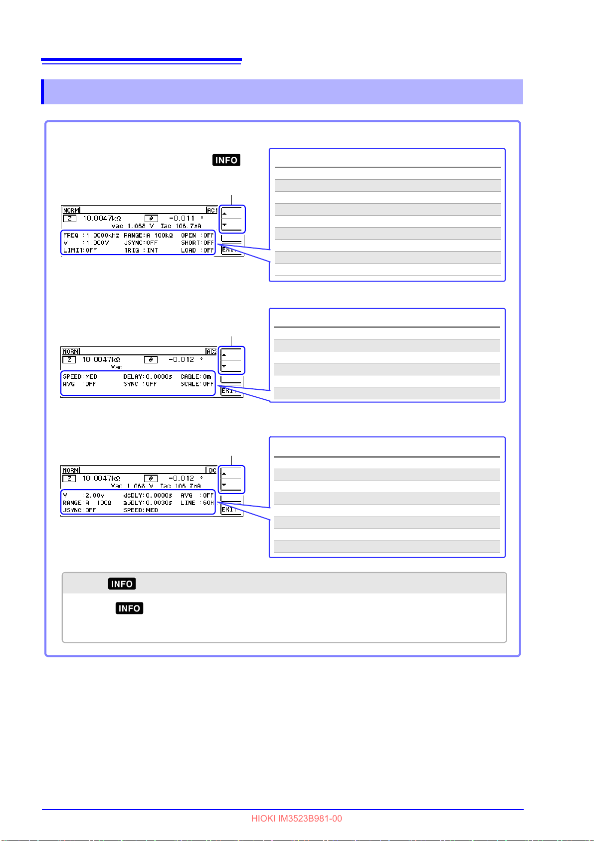
20
AC1 Screen
Settings
FREQ Frequency
V Signal level
LIMIT Limit value
RANGE Measurement range
JSYNC Judge Synchronous setting
TRIG Trigger Setting
OPEN Open Circuit Compensation
SHORT Short circuit compensation setting
LOAD Panel load
This screen is displayed when the key
is pressed.
AC2 Screen
Settings
SPEED Measurement Speed
AVG Average setting
DELAY Trigger delay
SYNC Trigger Synchronous Output Function
CABLE Cable length compensation
SCALE Scaling
DC Screen
Settings
V Signal level
RANGE Measurement range
JSYNC Judgment synchronization setting
dcDLY DC delay
ajDLY Adjust delay
SPEED Measurement Speed
AVG Average setting
LINE Line frequency
Switches pages.
Switches pages.
Switches pages.
When is pressed
Pressing key on the Information screen causes the screen to transition as follows:
AC1 screen→AC2 screen→DC screen→ Back to Measurement screen
HIOKI IM3523B981-00
1.3 Screen Organization and Operation
1.3.9 Information Screen
Page 27
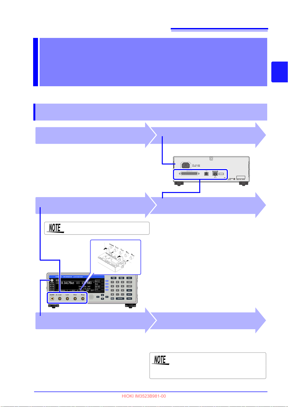
2.1 Preparation Flowchart
Installing the Instrument (p.6)
• USB Cable
•LAN Cable
• EXT I/O
Connect measurement cables, optional
Hioki probes or test fixture (p.24)
1
3
Connect to the test sample.
Remove the test sample and turn off the power
after use. (p.26)
Connecting
the Power Cord (p.23)
2
Connect the external interface
(as needed)
Turning Power On (p.26)
4
Make instrument settings (p.31)
When performing DC resistance measurement,
be sure to set the line frequency before starting
measurement.
See "4.3.4 Setting the Line Frequency" (p. 70)
Confirm that the instrument is turned off.
HIOKI IM3523B981-00
Measurement Preparations Chapter 2
Be sure to read the "Operating Precautions" (p. 6) before installing and connecting this instrument.
Refer to "Appendix9 Rack Mounting"(p. A13) for rack mounting.
2.1 Preparation Flowchart
21
2
Chapter 2 Measurement Preparations
Page 28
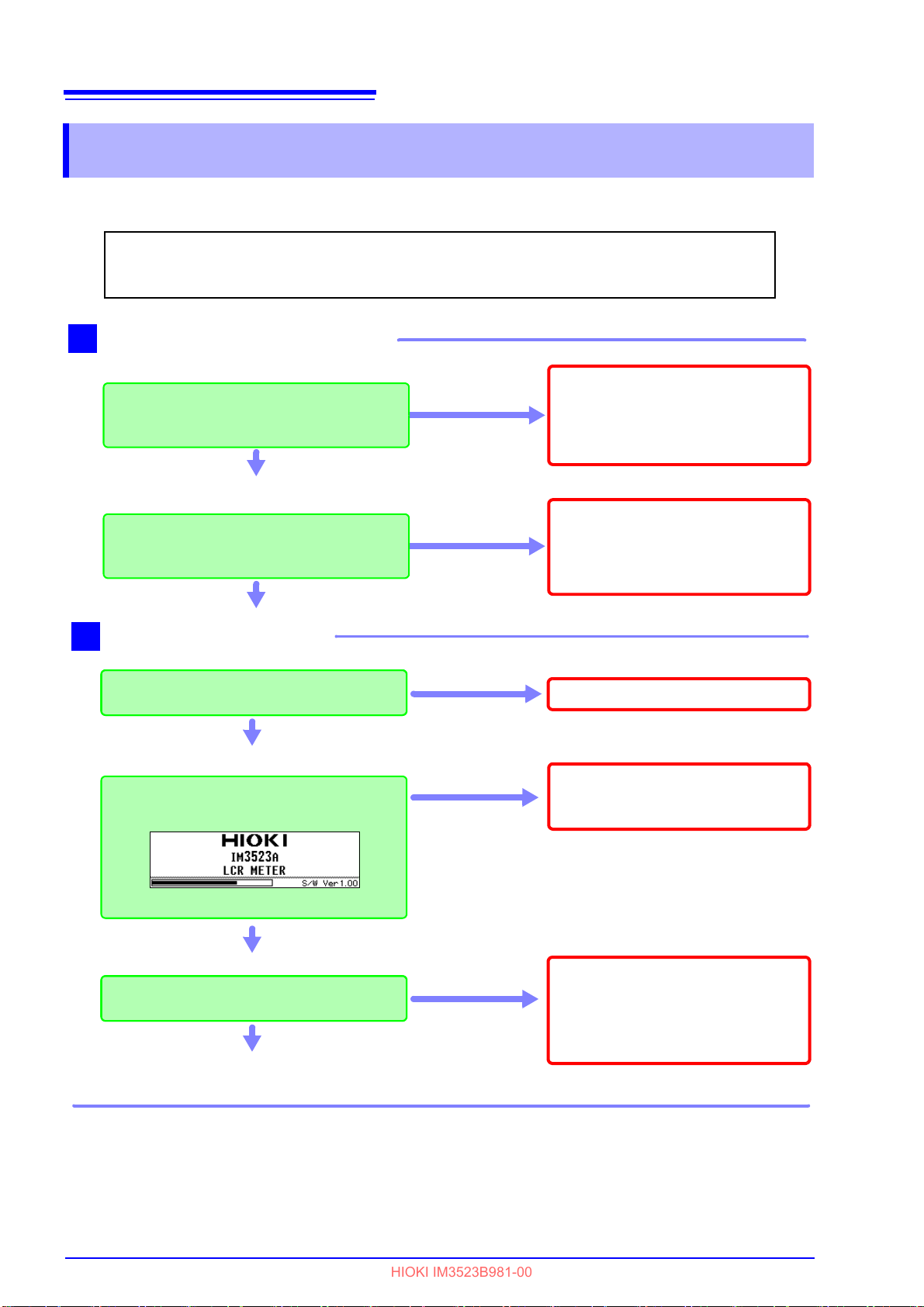
22
Do not use the instrument if damage
is found, as electric shock or shortcircuit accidents could result.
Contact your dealer or Hioki representative.
Metal Exposed
Is the power cord insulation torn, or is any
metal exposed?
1
No Metal Exposed
Before using the instrument for the first time, verify that it operates normally to ensure that no
damage occurred during storage or shipping. If you find any damage, contact your dealer or
Hioki representative.
Peripheral Device Inspection
Is the insulation on a measurement
cable torn, or is any metal exposed?
Metal Exposed
If there is any damage, measured values may be unstable and measurement errors may occur. Replace the
cable with an undamaged one.
No Metal Exposed
If damage is evident, request repairs.
Yes
Is damage to the instrument evident?
Instrument Inspection
When turning power on
Does the opening screen appear
(model no., version no.)?
No
2
The power cord may be damaged, or
the instrument may be damaged internally. Request repairs.
Is there an error display on the Opening
screen?
No
Yes
The instrument may be damaged
internally. Request repairs.
See "11.2 Troubleshooting" (p. 211)
"11.3 Error Display" (p. 216)
An error indication
occurs (ERR)
No
Inspection complete
Opening screen
HIOKI IM3523B981-00
2.2 Pre-Operation Inspection
2.2 Pre-Operation Inspection
Please read the "Operating Precautions" (p. 6) before use.
Page 29

2.3 Connecting the Power Cord
1 Confirm that the power cord matches the line voltage, and plug
it into the power inlet on the instrument. (AC100 V to 240 V)
2 Plug the other end of the power cord into an outlet.
The POWER button on the instrument’s front panel will
flash
red.
If power is interrupted while the instrument is
operating, it will
start back up immediately when power is restored.
(when the circuit breaker is turned back on, etc.)
Rear
Power inlet
Connection Procedure
HIOKI IM3523B981-00
2.3 Connecting the Power Cord
23
Confirm the supply voltage to the instrument matches the supply voltage indicated on the
instrument before connecting the power cord to the instrument. Connection to an improper
supply voltage may damage the instrument and present an electrical hazard.
Connect the power cord to the power inlet on the instrument, and plug it into an outlet.
2
Chapter 2 Measurement Preparations
Page 30
24
HIOKI IM3523B981-00
2.4 Connect measurement cables, optional Hioki probes or test fixture
2.4 Connect measurement cables, optional
Hioki probes or test fixture
Before using the instrument, make sure that the insulation on the voltage cords is
undamaged and that no bare conductors are improperly exposed. Using the instrument in such conditions could cause an electric shock, so contact your dealer or
Hioki representative for replacements.
• For safety reasons, disconnect the power cord when the instrument is not used.
• To avoid damaging the power cord, grasp the plug, not the cord, when unplugging it from
the power outlet.
• Do not apply a voltage to the measurement terminals. Doing so may damage the instru-
ment.
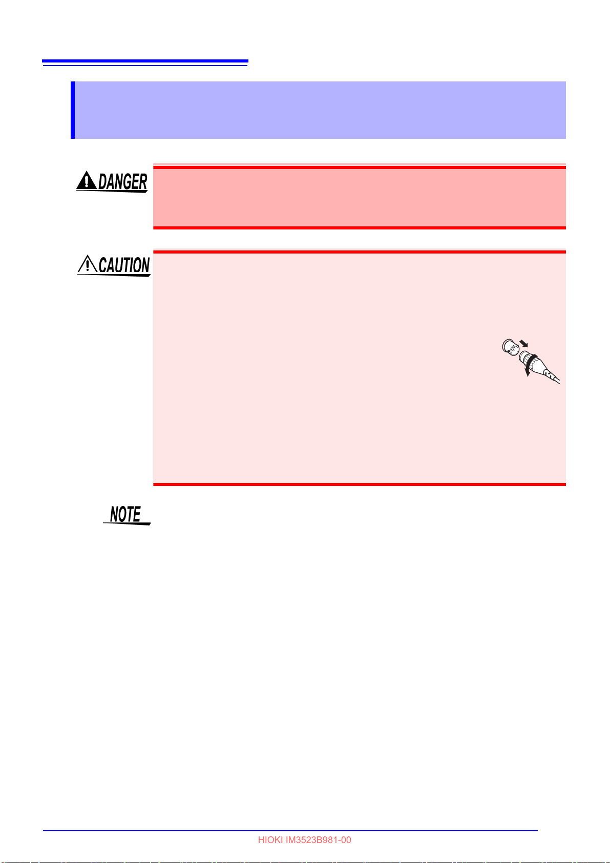
• When disconnecting the BNC connector, be sure to release the lock
before pulling off the connector. Forcibly pulling the connector without
releasing the lock, or pulling on the cable, can damage the connector.
• To avoid breaking the cables or probes, do not bend or pull them.
• Avoid stepping on or pinching cables, which could damage the cable
insulation.
• Keep the cables well away from heat sources, as bare conductors could be exposed if
the insulation melts.
• Keep in mind that, in some cases, conductors to be measured may be hot.
• To avoid electric shock, do not exceed the lower of the ratings shown on the instrument
and connection cords.
• Use only the specified connection cables. Using a non-specified cable may result in
incorrect measurements due to poor connection or other reasons.
Refer to "Options" (p. 3) for details.
• Before using a fixture or the like, read the instruction manual supplied with the product to
be used.
Page 31

25
Connecting a measurement cable/fixture
Connect directly to the
measurement jacks with
the label side up, and affix
with the levers on the left
and right.
(When using the optional 9140-10 or L2001)
Connect the red plugs to the H
CUR
and H
POT
jacks, and
the black plugs to the L
CUR
and L
POT
jacks.
(When using the optional 9500-10)
BNC plug of H
CUR
, H
POT
, L
CUR
and L
POT
connected
properly to the measurement terminals of each of the instruments.
Black
Red
Points to pay attention to when making your own probe
• Use 50 Ω coaxial cable for the measurement cable.
• Ensure that the length of the cable is the same as that set for the instrument. (1m)
• The cable length is defined as the length from the tip of th
e BNC connector to the tip of the probe electrode.
• Make the portion of the core wire tha
t is exposed as short as possible.
• Connect the H
CUR
, L
CUR
, H
POT
, and L
POT
shield pairs at the measurement object side.
(Ensure that a shield is not conn
ected to a core wire.)
Measurement Terminal Configuration
Fixture
Normal mode
HIOKI IM3523B981-00
2.4 Connect measurement cables, optional Hioki probes or test fixture
2
Chapter 2 Measurement Preparations
• As a rule, only HIOKI-brand probes, fixtures, and other components (options) should be
used. Use of probes that you have built yourself may prevent the instrument from perform
ing in a matter that satisfies its specifications.
See "Options" (p. 3)
• If all four terminals are disconnected, a meaningless number may be displayed on the unit.
-
Page 32

26
To ensure that measurements fulfill the
degree of accuracy described in the specifications, allow the instrument to warm up
for at least 60 minutes after it is turned on.
Press the POWER button (it lights green).
When the power is turned on, the same setting as when the power was last turned off appears.
Lights green
ON the main power in the state, hold down the front POWER switch 1 second approximately.
(it lights red)(Standby state*).
Lights red
Disconnect the power cord from the outlet to extinguish the POWER button light.
When power is turned on again, operation resumes with the same settings as
when last turned off.
HIOKI IM3523B981-00
2.5 Turning the Power On and Off
2.5 Turning the Power On and Off
Once you’ve connected probes and test fixtures, connect the power cord’s plug to a power outlet.
• Before turning the instrument on, make sure the supply voltage matches that indi-
cated on its power connector. Connection to an improper supply voltage may damage the instrument and present an electrical hazard.
• Be careful to avoid connecting the supply voltage improperly. Doing so may damage the instrument's internal circuitry.
• To avoid electrical accidents and to maintain the safety specifications of this instrument, connect the power cord only to a 3-contact (two-conductor + ground) outlet.
• To avoid shock and short circuits, turn off all power before connecting probes.
Turning main power on
Turning main power off
*: Standby state
The instrument is in the standby state when
ing for POWER button input to be detected. To allow POWER bu
circuitry is operating with power consumption of approximately 4 W.
If a power outage (e.g., breaker trip) occurs when the instrument is on, it will automatically
turn on again when power is restored. (without pressing the POWER button)
measurement has been stopped and the instrument is wait-
tton input to be detected, some internal
Page 33

27
For the connection procedure, refer to the
instruction manual supplied with the fixture.
Displays the Basic Settings screen.
Select
Setting example
PARA
Display parameters
:MAIN :Cs
:SUB :D
FREQ
Measurement frequency
:1.0000 kHz
LEVEL
Measurement signal mode
:
Open circuit voltage mode (V)
Measurement signal level
:1.000 V
LIMIT
Voltage and current limit
:OFF
RANGE
Measurement range
:AUTO
JUDGE
SYNC
Judgment
synchronization function
:OFF
TRIG
Trigger
:INT
LIST Displays the LIST Settings screen.
HIOKI IM3523B981-00
Measurement Example Chapter 3
Measuring a Laminated Ceramic Capacitor
Necessary items : 9263 SMD test fixture
Laminated ceramic capacity yo
Connect the 9263 SMD test fixture to the measurement terminals.
u want to measure
1
Open the Basic Settings screen.
2
3
Chapter 3 Measurement Example
3
Set the measurement conditions.
Page 34

28
Displays the LIST Settings screen.
2
1
Select
Select
Setting example
SPEED
Measurement speed
:MED
AVG
Average
:001
DELAY
Trigger Delay
:0s
SYNC
Trigger Synchronous Output
:OFF
For the connection procedure of the test
sample,refer to the instruction manual
supplied with the fixture.
• When you want to judge the measurement results
See "4.4.1 Making Judgments Based on Upper and Lower Limit Values (Comparator Measurement
Mode)" (p. 76)
• When you want to save the measurement results
See "4.5.1 Saving Measurement Results (Memory function)" (p. 97)
HIOKI IM3523B981-00
4
5
Select [LIST] on the Basic Settings screen to open the LIST Settings screen.
Set the measurement conditions for the respective ranges.
6
7
Connect the test sample to the 9263 SMD test fixture.
Check the measurement results.
Page 35

4.1 About LCR function
Indicates the
measurement mode.
Indicates the
loaded panel
number. (p.165)
Indicates the usage
status of internal
memory. (p.97)
Indicates the parameter
and measurement value.
Indicates some of the measurement
conditions
From the left, frequency, measurement
signal level, measurement range,
measurement speed, trigger settings.
Monitor values
Vac,Vdc:Voltage across the terminals
of the sample
I
ac,Idc
:Current passing through
the sample
Menu keys
[BASIC] :Configures basic settings. (p.31)
[Rdc] :Configures DC resistance
measurement settings. (p.61)
[ADVNC] :Configures application
settings. (p.97)
[SYS] :Configures system settings.
(p.171)
Indicates error
messages and other
information. (p.216)
HIOKI IM3523B981-00
LCR Function Chapter 4
4.1 About LCR function
The LCR function allows you to measure the impedance, phase angle, and other items by applying any
frequency or level (effective value) signal to the element you want to measure. This function is suitable for
evaluating the passive element of a capacitor, coil, or the like.
Measurement screen
The Measurement screen allows you to make measurements while reviewing measurement conditions.
When the ins
when the power was turned off. For more information about the screen layout, see (p.12).
trument is turned back on, the display will reflect the measurement mode that was in use
29
4
Chapter 4 LCR Function
Page 36

30
Sets the measurement result judgment conditions
(when performing comparator/BIN measurement).
Loads measurement conditions.
Configures compensation functions.
Allows you to check detailed measurement conditions.
Toggles the display between the monitor value and comparator/BIN limit values
(when comparator/BIN measurement has been configured). For more information, see below.
When performing comparator measurement.
(Switch between the limit and monitor values with the keys.)
Limit values
Monitor values
When performing BIN measurement.
(Switch between the limit and monitor values with the tenkey ( to , ) or the keys.)
BIN1 Limit values
BIN10 Limit values
Monitor values
••••••••••••••••••••••••••
Toggles the display between the monitor value and
BIN limit values (when BIN measurement has been
configured). For more information, see below.
to : Allow you to check the BIN limit values. ( : BIN10)
: Allows you to check the monitor value.
HIOKI IM3523B981-00
4.1 About LCR function
Keys that can be used on the Measurement screen
When the measurement value is outside the guaranteed accuracy range, will be
shown on the error message display. If you encounter this issue, the following factors may be
at play. Change the measurement conditions after checking the guaranteed accuracy range
as described in "10.2 Measurement Range and Accuracy" (p.200), or use the measurement
value as a reference value.
• If the measurement signal level is too low: Increase the measurement signal level.
• If the current measurement range (when using the HOLD setting) is not appropriate: Set
the range to the optimal measurement range using AUTO ranging or change the measurement range manually.
Page 37

31
Displays the Basic Settings screen.
Select
Displays the Main Parameter Settings
screen.
ENTER
2
1
Select
Accepts the selected parameter and
returns to the Basic Settings screen.
ENTER
2
1
HIOKI IM3523B981-00
4.2 Setting Basic Settings of Measurement Conditions
4.2 Setting Basic Settings of Measurement
Conditions
Measurement conditions for DC resistance measurement are configured on a different
screen.
See "4.3 Setting DC Resistance Measurement" (p.61)
4.2.1 Setting Display Parameters
You can select a main and sub parameter from the 15 measurement parameters to display.
See "Appendix1 Measurement Parameters and Calculation formula"(p. A1)
"Appendix7 Series Equivalent Circuit Mode an
d Parallel Equivalent Circuit Mode"(p. A10)
4
1
2
3
Open the Basic Settings screen.
Select [MAIN] under [PARA].
Set the main parameter.
Chapter 4 LCR Function
Page 38

32
Select
1
Displays the Sub Parameter Settings screen.
ENTER
2
Select
Accepts the selected parameter and
returns to the Basic Settings screen.
ENTER
* The phase angle θ is shown based on the impedance Z.
When performing measurements using admittance Y as the reference, the sign of the impedance Z phase angle q will be reversed.
List of parameters
Impedance (Ω) Conductance (S)
Admittance (S) Reactance (Ω)
Impedance phase angle (°)
*
Inductance in series equivalent circuit mode
(H)
Effective resistance in series equivalent circuit mode = ESR (Ω)
Inductance in parallel equivalent circuit mode
(H)
Effective resistance in parallel equivalent circuit mode (Ω)
Q factor
Static capacitance in series equivalent circuit
mode (F)
Susceptance (S)
Static capacitance in parallel equivalent circuit (F)
DC Resistance (Ω)
Loss coefficient = tanδ
Display no measurement parameter in the
chosen position.
HIOKI IM3523B981-00
4.2 Setting Basic Settings of Measurement Conditions
Select [SUB] under [PARA].
4
Set the sub parameter.
5
Page 39

4.2 Setting Basic Settings of Measurement Conditions
DIGIT
10KEY
Displays the Basic Settings screen.
Select
Displays the Tenkey Input screen.
ENTER
1
2
HIOKI IM3523B981-00
4.2.2 Setting the Measurement Frequency
Set the frequency of the signal to apply to the test sample.
For some test samples, the value may vary depending on the measurement frequency.
You can enter the frequency using either digit or tenkey input.
Setting the frequency with tenkey input
Open the Basic Settings screen.
1
33
4
Chapter 4 LCR Function
2
3
Select [FREQ].
The Tenkey Input screen will be displayed.
Page 40

34
10KEY
Increases the unit
Decreases the unit
Accepts the entered value
• The keys will be disabled until you enter a value.
• If you set a frequency of 200 kHz or higher, the frequency will automatically revert to 200 kHz.
• If a frequency of less than 40 Hz is set, the value will be automatically changed to 40 Hz.
"Chapter 10 Specifications" (p.195)
1
15.5
15.
If you make a mistake:
Press key and reenter the value.
15.5
15
k
15.500kHz
Returns to the Basic Settings screen.
ENTER
HIOKI IM3523B981-00
4.2 Setting Basic Settings of Measurement Conditions
Enter the desired value with the tenkey and accept it with the key.
4
Settable range:40 Hz to 200 kHz
5
Page 41

Set each digit (DIGIT)
Displays the Basic Settings screen.
Select
Displays the Frequency Setting screen.
ENTER
2
1
Selects digit entry.
DIGIT
Increases the value.
Decreases the value.
Select
1
2
Selects the digit to change.
The digits in the measurement frequency can also be changed using the keys.
HIOKI IM3523B981-00
Open the Basic Settings screen.
1
Select [FREQ].
2
35
4.2 Setting Basic Settings of Measurement Conditions
4
Chapter 4 LCR Function
3
4
Select [DIGIT].
Enter the desired value.
Settable range: 40 Hz to 200 kHz
Page 42

36
Select
Multiplies the measurement frequency
by 10 or .
10
1
1
2
Returns to the Basic Settings screen.
HIOKI IM3523B981-00
4.2 Setting Basic Settings of Measurement Conditions
Change the unit and decimal point.
5
6
Page 43

4.2 Setting Basic Settings of Measurement Conditions
Open circuit voltage mode (V)
The value of the open circuit voltage is set.
Constant voltage mode (CV)
The value of the voltage between the terminals of the object under
test is set.
Constant current mode (CC)
The value of the current flowing through the object under test is set.
Displays the Basic Settings screen.
Select
Open circuit voltage mode (V)
Constant voltage mode (CV)
Constant current mode (CC)
HIOKI IM3523B981-00
4.2.3 Setting the Measurement Signal Level
The value of the test signal level may change according to the sample which is being tested.
This instrument is possible to vary the
range using the following three methods.
Selecting constant voltage or cons
use of software feedback control.
Do not switch between V, CV and CC while the test sample is still connected to the measurement terminals. Doing so ma
level of the test signal applied to the object under test over a wide
tant current mode will result in increased measurement times due to
y damage the test sample.
37
4
Chapter 4 LCR Function
1
2
• In constant voltage (CV) mode, the generated voltage is controlled using software feed-
back so that the set constant voltage value is a
recent measurement is output as the generated voltage initial value, a voltage in excess
of the set constant voltage value may be applied before feedback control is active if the
sample’s impedance is higher than that of the last measured sample.
• In constant current (CC) mode, the generated voltage is controlled using software feed-
back so that the set constant current value is applied. Since the voltage used for the most
nt measurement is output as the generated voltage initial value, a current in excess of
rece
the set constant current value may be applied before feedback control is active if the sample’s impedance is lower than that of the last measured sample.
Open the Basic Settings screen.
Select [LEVEL].
pplied. Since the voltage used for the most
Select the measurement signal mode.
3
Page 44

38
DIGIT
Increases the value.
Select
2
1
Decreases the value.
Measurement signal level range
Measurement
signal mode
Setting range
V, CV 0.005 V to 5.000 V
CC 0.01 mA to 50.00 mA
Selects the digit to change.
Returns to the Measurement screen.
HIOKI IM3523B981-00
4.2 Setting Basic Settings of Measurement Conditions
Select the [LEVEL] voltage or current value and change the value.
4
The accuracy of testing varies according to the test signal level.
See
"10.2 Measurement Range and Accuracy" (p.200)
5
If the measurement value is outside the accuracy guarantee, will be displayed at
the top of the screen. Check the accuracy guarantee range in "10.2 Measurement Range
and Accuracy" (p.200) and either change the measurement conditions or make the measurement value a reference value.
• If the measurement signal level is too low: Increase the measurement signal level.
• If the current measurement range (when using the HOLD setting) is not appropriate: Set
range to the optimal measurement range using AUTO ranging or change the measure-
the
ment range manually.
Page 45

4.2 Setting Basic Settings of Measurement Conditions
Output impedance
Sample
CC
CV
HL
V
Constant current mode (CC)
You should select this if you wish to set the
current passing through the object to be
tested to a constant value.
Constant voltage mode (CV)
You should select this if you wish to set the
voltage across the terminals of the object
to be tested to a constant value.
Open circuit voltage mode (V)
This voltage value is the value which is applied across the two
terminals of the series combination of the object which is being
tested and the output impedance. As for the voltage which is applied across the terminals of the object which is being tested (by
itself), if required, you should either check
the monitor voltage value, or select constant voltage (CV) and
set a voltage value across these terminals.
Open circuit voltage mode (V) and Constant voltage mode (CV) setting
9.15-0 jjXmRmZm
()
fC
Xm
π
2
1
−
=
9.15100' jZmRoZm
Ro: Output resistance (100 [Ω])
[]
Ω
×Ω
=
×
=
3.101
9.15
'VoZm
VoZm
Vm
Vo: generator output
HIOKI IM3523B981-00
About the test signal mode
Relationship between the measurement signal mode of the instrument and the sample is as follows.
39
4
Chapter 4 LCR Function
For setting range and accuracy
Open circuit voltage setting range Open circuit voltage accuracy Output impedance
0.005 V to 5.000 V ±10% rdg ±10 mV
Depending on the sample, you may not be able to perform constant voltage measurement. In
this situation, the following mark will be displayed:
Constant voltage measurement will not be performed.
Change the constant voltage level so that it is less than or equal to the displayed Vac monitor
values.
Example: Range in which constant voltage operation is supported when measuring a 1 μF C
at 10 kHz
The sample impedance Zm is as follows:
The impedance Zm' observed from the generator is as follows:
Accordingly, the voltage Vm across
[] []
ΩΩ=+=
[] []
Ω−Ω=+=
both leads of the sample is as follows:
100 Ω ±10 Ω
Because the generator output voltage range is 5 mV to 5 V for 10 kHz, the CV operation
range per the above expression is Vm = 0.8 mV to 0.78 V.
[]
Page 46

40
Constant current mode (CC) setting
28.60 jjXmRmZm
fLXmπ2
Ro: output resistance (100 [Ω])
28.6100' jZmRoZm
Vo: generator output
[]
Ω==2.100'
Im
Vo
Zm
Vo
Im
HIOKI IM3523B981-00
4.2 Setting Basic Settings of Measurement Conditions
However, the constant current operation range differs depending on the test sample to be measured.
Constant current setting range Constant current accuracy Output impedance
0.01 mA to 50.00 mA
Depending on the sample, you may not be able to perform constant current measurement.
In this situation, the following mark will be displayed:
Constant current measurement will not be performed.
Change the constant current level so that it is less than or equal to the displayed Iac monitor
value.
±10% rdg ±10 μA 100 Ω ±10 Ω
Example:
Range in which constant current operation is supported when measuring a 1 mH L at 1 kHz
The sample impedance Zm is as follows:
[] []
The impedance Zm' observed from the generator is as follows:
[] []
Accordingly, the current Im acr
Since the generator output voltage range is 5 [mV] to
age mode (V) and Constant voltage mode (CV) setting" (p. 39) table, constant current operation is supported for Im values of 49.9 [μA] to 49.9 [mA] as per the above equation.
oss both leads of the sample is as follows:
Ω−Ω=+=
Ω−Ω=+=
5 [V] based on the "Open circuit volt-
=
Page 47

4.2 Setting Basic Settings of Measurement Conditions
When open circuit voltage mode (V)
or constant voltage mode (CV) is set
Set the current limit.
When constant current mode(CC) is set
Set the voltage limit.
Displays the Basic Settings screen.
Select
• When the measurement signal mode is a voltage (V, CV)
• When the measurement signal mode is a current (CC)
• The measurement signal level can be checked using the monitor display.
• The monitor display is different for V, CV, and CC.
First set the measurement signal mode, and thereafter set the voltage or current limit.
The setting for voltage or current limit changes automatically to current or voltage
limit,according to the present measurement signal mode setting.
See "4.2.3 Setting the Measurement Signal Level" (p.37)
HIOKI IM3523B981-00
4.2.4 Limiting the Voltage or Current Applied to the Sample (Limit Values)
Depending on the measurement signal level, in some cases it is possible to damage the sample which is
being tested by applying to it a voltage or a current greater than its rated value.
To avoid such damage, you can set a limit value to limit the voltage applied to the sample or the current
that flows to the
Enabling the limit function will result in
control.
Open the Basic Settings screen.
sample.
increased measurement times due to use of software feedback
1
41
4
Chapter 4 LCR Function
Select [LIMIT].
2
Page 48

42
Disables the limit function.
Enables the limit function.
Increases the value.
2
1
Select
Decreases the value.
Limit range
Measurement
signal mode
Set limit Setting range
V, CV Current limit 0.01 mA to 50.00 mA
CC Voltage limit 0.005 V to 5 V
Current limit accuracy
Frequency Accuracy
40 Hz to 200 kHz
±10 %rdg±10
μA
Voltage limit accuracy
Frequency Accuracy
40 Hz to 200 kHz ±10% rdg±10 mV
Selects the digit to change.
DIGIT
When the limit function is on, the following marks may be displayed.
Example: When constant voltage mode (CV) setting
If the voltage or current which is applied to the
sample under test exceeds the limit value
(the current exceeding the limit value flows
through the sample even when the open-circuit
voltage is set to minimum value.)
Lower the measurement signal level so that the
limit value is not exceeded.
If the test signal level which is being applied to the
sample under test exceeds the limit value. Then the
test signal level is stopped changing.
At this time, the voltage or current which exceeds
the limit value is not being applied to the sample
under test. You should change the test signal level
so that it does not exceed the limit value.
Returns to the Measurement screen.
HIOKI IM3523B981-00
4.2 Setting Basic Settings of Measurement Conditions
Set the limit function to either [ON] or [OFF].
3
Enter the current limit value or voltage limit value.
4
5
Page 49

4.2 Setting Basic Settings of Measurement Conditions
The most suitable test range is set automatically.
(Automatically sets the optimal measurement range when measuring
samples whose impedance varies greatly with the frequency, or
unknown samples.)
AUTO
HOLD
Fixes the measurement range. The range is set manually.
(Fixing the range allows high-speed measurement.)
JUDGE SYNC
Automatically sets the optimal range for the comparator and BIN measurement judgment standards. (Automatically sets the optimal range
relative to the comparator and BIN measurement judgment standards
when the sample’s impedance varies greatly with the frequency.)
HIOKI IM3523B981-00
4.2.5 Setting the Measurement Range
There are three methods for setting the measurement range: AUTO, HOLD, and JUDGE SYNC.
43
4
Chapter 4 LCR Function
The ranges are all defined in terms of impedance. Therefore, for a parameter other than
impedance, the value is obtained by calculating from the measured values of |Z| and θ.
See "Appendix1 Measurement Parameters and Calculation formula"(p. A1)
Using the HOLD or AUTO settings when the J
JUDGE SYNC setting to be automatically disabled.
UDGE SYNC setting is on causes the
Page 50

44
Displays the Basic Settings screen.
Select
Sets the range to AUTO.
• The ranges that can be selected vary with the frequency. (p.46)
• Outside the accuracy guarantee range, AUTO ranging may not function properly, preventing a
range from being selected. If this occurs, check the accuracy guarantee range in "10.2 Measurement Range and Accuracy" (p.200) and change the measurement conditions.
Returns to the Measurement screen.
HIOKI IM3523B981-00
4.2 Setting Basic Settings of Measurement Conditions
Setting AUTO Ranging
Open the Basic Settings screen.
1
Select [RANGE].
2
Set the measurement range to [AUTO].
3
4
AUTO range limit function
The AUTO range limit function allows you to limit the AUTO ranging range. The AUTO range limit function
can be set using communications commands only. It cannot be set from the instrument.
See Communications commands in the included LCR Application Disk documentation (:RANGe:AUTO:LIMit)
Page 51

Setting HOLD Ranging
Displays the Basic Settings screen.
Select
Sets the range to HOLD.
Displays the Range Selection screen.
ENTER
Select
2
1
HIOKI IM3523B981-00
Open the Basic Settings screen.
1
Select [RANGE].
2
45
4.2 Setting Basic Settings of Measurement Conditions
4
Chapter 4 LCR Function
3
4
Set the measurement range to [HOLD].
To select the measurement range.
Page 52

46
Set the test range according to the combined impedance value of the sample to be tested
and the test cables.
Select
Changes the range to the selected
range and returns to the Basic Settings
screen.
ENTER
Frequency
Ranges that can
be selected
Range Settings screen
DC
40.000 Hz to 10.000 kHz
All range
10.001 kHz to 100.00 kHz
100 mΩ to 10 MΩ
100.01 kHz to 200.00 kHz
100 mΩ to 1 MΩ
The ranges that can be selected vary with the frequency.
Range Accuracy guaranteed range AUTO Ranging Range
100 MΩ 8 MΩ to 200 MΩ 8 MΩ to
10 MΩ 800 kΩ to 100 MΩ 800 kΩ to 10 MΩ
1 MΩ 80 kΩ to 10 MΩ 80 kΩ to 1 MΩ
100 kΩ 8 kΩ to 1 MΩ 8 kΩ to 100 kΩ
10 kΩ 800 Ω to 100 kΩ 800 Ω to 10 kΩ
1 kΩ 80 Ω to 10 kΩ 80 Ω to 1 kΩ
100 Ω 8 Ω to 100 Ω 8 Ω to 100 Ω
10 Ω 800 mΩ to 10 Ω 800 mΩ to 10 Ω
1 Ω 80 mΩ to 1 Ω 80 mΩ to 1 Ω
100 mΩ 10 mΩ to 100 mΩ 0 Ω to 100 mΩ
HIOKI IM3523B981-00
4.2 Setting Basic Settings of Measurement Conditions
To select the measurement range.
5
Page 53

47
HIOKI IM3523B981-00
4.2 Setting Basic Settings of Measurement Conditions
• The guaranteed accuracy range varies depending on the measurement conditions. (p.196)
• Changing the measurement range while the
enables the HOLD setting.
• The measurement range is determined according to the test range setting. If the display for
the me
cannot be performed using the currently set test ra
ing so as to select the most suitable test range automatically, or you should set a more suitable test range manually. If a measurement result is outside the display range (p.195),
• The guaranteed accuracy range is for the
• The AUTO ranging range is the range within whic
AUTO range limit function is enabled, the range will not be switched outside the defined
limit range.
• In the case of a test sample whose impedance chan
testing is being performed with HOLD set, it may happen, when the frequency is changed
over, that measurement cannot be continued to be performed upon the same test
range.You should change the test range if this happens.
• The test range setting is made according to the comb
ple being tested and the test cables. Therefore it can
the test range is held with HOLD only upon the basis of the impedance of the sample
under test. If this happens, you should change the test range, making reference to "6.1
Setting Open Circuit Compensation" (p.125) and "6.2 Short Circuit Co
(p.136).
asured value shows or , that means that measurement
is displayed.
measurement values before compensation.
AUTO setting is enabled automatically
nge. Either you should set AUTO rang-
h the AUTO range is switched. When the
ges according to the frequency, when
ination of the impedances of the sam-
happen that testing is not possible,if
mpensation"
4
Chapter 4 LCR Function
If the measurement value is outs
the top of the screen.
In this case, you should consider the following possible causes, and you should either
change the test conditions while checking the accuracy assured ranges "10.2 Measurement
Range and Accuracy" (p.200), or you should consider the measured values as values for reference.
• Perhaps the test signal level is too low
• If the current measurement range (during HOLD settin
AUTO range, or change the range by manual.
ide the accuracy guarantee, will be displayed at
, increase the test signal level.
g) is not appropriate, set again in the
Page 54

48
Displays the Basic Settings screen.
Select
Disables the JUDGE SYNC setting.
Enables the JUDGE SYNC setting.
Returns to the Measurement screen.
HIOKI IM3523B981-00
4.2 Setting Basic Settings of Measurement Conditions
JUDGE SYNC setting
When the judgment synchronization setting is enabled and you wish to set an optimal range based on the
comparator or BIN measurement judgment standards, it is not necessary to set the range using the
HOLD setting. When performing comparator or BIN measurement with a sample whose impedance varies greatly with the frequency, you can fix the measurem
ment standard.
This setting is only available when the judgment standards have been set for comparator and
BIN measurement. (p.75)
When judgment standards have been set for comparator and BIN measurement with this
setting on, the range will be automatically switched to the optimal range. However, the AUTO
range is used when no judgment standards have been set.
Open the Basic Settings screen.
ent range to an optimal value relative to the judg-
1
2
3
4
Select [JUDGE SYNC].
Turn the JUDG SYNC setting [OFF] or [ON].
• The ranges that can be selected vary with the frequency. (p.46)
• When only θ, D, or
• Because the phase angle cannot be calculated for some combinations of parameters, the
nge is determined from ideal values. For more information, see the table below.
ra
See "Parameter combination conditions for the JUDGE SYNC setting" (p. 49)
Q has been set, AUTO functionality is used.
Page 55

49
Parameter combination conditions for the JUDGE SYNC setting
AC OFF Z Y Rs Rp X G B Ls Lp Cs Cp
θ
D Q
OFF
×
× × ×
Z
Y
Rs
Rp
X
G
B
Ls
Lp
Cs
Cp
θ
×
× × ×
D
×
× × ×
Q
×
× × ×
Sub parameter
Main parameter
×
Invalid setting (treated as AUTO range)
Invalid setting (treated as AUTO range)
Set from ideal value since phase angle
cannot be calculated.
Valid setting
HIOKI IM3523B981-00
4.2 Setting Basic Settings of Measurement Conditions
4
Chapter 4 LCR Function
Page 56

50
Internal Trigger
Automatically generates a trigger signal internally to repeat
measurement.
External trigger
Measurements are triggered by an external signal.
The trigger is input manually or using external I/O or another
interface.
Displays the Basic Settings screen.
Select
Set the Internal Trigger.
Set the External Trigger.
When [EXT] is selected
There are the following three types of input method for a trigger.
• Press key on the screen to manually input a trigger: Measurement is per-
formed once.
• Input via EXT I/O: Measurement is performed once each time a negative logic pulse
signal is applied.
See "Connector Type and Signal pin assignments" (p. 178)
• Input from interface: Measurement is performed once when
*TRG is transmitted.
See Communications commands in the included LCR Application Disk documenta-
tion
Returns to the Measurement screen.
HIOKI IM3523B981-00
4.2 Setting Basic Settings of Measurement Conditions
4.2.6 Measuring at User-specified Timing
(Trigger Measurement)
Triggering is the process of controlling the start and stop of recording by specific signals or conditions (criteria). When recording is started or stopped by a specific s
ing occurs”.
With this instrument, you can select t
Open the Basic Settings screen.
he following two types of trigger.
ignal, we say the trigger is “applied” or “trigger-
1
2
3
Select [TRIG].
Set the trigger setting to [INT] or [EXT].
4
Page 57

4.2 Setting Basic Settings of Measurement Conditions
Speed
Average
Trigger Delay
Trigger Synchronous Output Function
Measurement
range
HIOKI IM3523B981-00
4.2.7 Setting Measurement Conditions for Individual Ranges
The measurement speed, averaging settings, trigger delay, and trigger synchronous output function can
be configured for individual ranges. The same settings can also be used for all ranges. (p.60)
List screen layout
51
4
Chapter 4 LCR Function
Page 58

52
Displays the Basic Settings screen.
Select
Displays the List screen. (settings
screens for individual ranges)
ENTER
2
1
Ranges that can be selected:
100 m
Ω/1 Ω/10 Ω/100 Ω/1 kΩ/10 kΩ/100 kΩ/1 MΩ/10 MΩ/100 MΩ
Select
Opens a settings window.
ENTER
1
2
Setting Description Window
SPEED Sets the measurement speed. (p.53)
AVG Sets the average. (p.54)
DELAY Sets the trigger delay. (p.56)
SYNC
Sets the trigger synchronous output function.
(p.57)
HIOKI IM3523B981-00
4.2 Setting Basic Settings of Measurement Conditions
Selecting range settings to change
Open the Basic Settings screen.
1
Select [LIST].
2
Select the range setting you wish to change.
3
Page 59

4.2 Setting Basic Settings of Measurement Conditions
Select
Open the Speed Settings window.
ENTER
Select
To select the measurement speed.
FAST Performs high-speed measurement.
MED This is the normal measurement speed.
SLOW Measurement precision improves.
SLOW2 Measurement accuracy is better than SLOW.
Accepts the setting and returns to
the List screen.
ENTER
Press the key to cancel the configuration
process and return to the List screen.
HIOKI IM3523B981-00
Setting the Measurement speed
The testing speed can be set. The slower the testing speed is, the more accurate are the results.
Select the range speed you wish to change on the List screen.
1
2
See "Selecting range settings to change" (p. 52)
Set the SPEED.
The measurement speed varies with the measurement conditions.
See "10.3 About Measurement Times and Measurement Speed" (p.207)
53
4
Chapter 4 LCR Function
3
• You can set the measurement speed at a greater level of detail with the waveform averag-
ing function.
• The speed cannot be set while the waveform averaging function is enabled.
Disable the waveform averaging function
See "4.5.2 Setting the Detection Signal Waveform Averaging Count (Waveform Averaging
Function)" (p.99)
before setting the speed.
Page 60

54
With internal trigger
A rolling average of the tested values over the set number of
times for averaging is always calculated backwards from the
present.When the sample to be tested is changed over, it takes a
little time for a certain stabilization time period until the results is
reliable.
With external trigger
An average of the test values is calculated over the set number of
times for averaging forwards from when the trigger is input.
M10
M9
M8
M7
M6
M5
M4
M3
M2
M1
M1
1
M1+M2
2
M1+M2+M3
3
M1+M2+M3+M4
4
M2+M3+M4+M5
4
M3+M4+M5+M6
4
M4+M5+M6+M7
4
M5+M6+M7+M8
4
M6+M7+M8+M9
4
M7+M8+M9+M10
4
Measurement points
Measurement value output
Moving average
Time
M10
M9M8M7M6M5M4M3
M2
M1
Time
Arithmetic mean
M1+M2+M3+M4
4
M5+M6+M7+M8
4
Measurement points
Measurement value output
HIOKI IM3523B981-00
4.2 Setting Basic Settings of Measurement Conditions
Displaying Average Values (Average set)
With the averaging function, the measured values can be averaged. Using this function, it is possible to
reduce fluctuations in the measured value display.
When the number of averaging times is 4, the number of m
easurements, measurement output points, and
measurement value calculation method during output are as follows.
Page 61

1
Opens the Averaging Setting window.
ENTER
Select
DIGIT
Select
1
Increases the value.
2
Decreases the value.
Reverts to the default value.
Selects the digit to change.
You can also change the value with the keys.
Accepts the setting and returns to the
List screen.
ENTER
Press the key to cancel the configuration
process and return to the List screen.
HIOKI IM3523B981-00
55
4.2 Setting Basic Settings of Measurement Conditions
On the List screen, select the range averaging count you wish to change.
See "Selecting range settings to change" (p. 52)
2
3
Set the averaging count.
Settable range: 1 to 256 times
4
Chapter 4 LCR Function
Page 62

56
Opens the Trigger Delay Setting window.
ENTER
Select
DIGIT
Select
1
Increases the value.
2
Decreases the value.
Selects the digit to change.
Reverts to the default value.
You can also change the value with the keys.
Accepts the setting and returns to the
List screen.
ENTER
Press the key to cancel the configuration
process and return to the List screen.
HIOKI IM3523B981-00
4.2 Setting Basic Settings of Measurement Conditions
Setting a delay before measurement data is acquired (trigger delay)
The delay time period from input of the trigger signal to measurement can be set. With this function it is
possible to ensure that testing is started after the connection condition of the object being tested and the
test cables has stabilized.
See "Trigger delays and the trigger synchronous output function" (p. 59)
On the List screen, select the range trigger delay you wish to change.
See "Selecting range settings to change" (p. 52)
1
Set the delay time.
2
Settable range: 0 to 9.9999 s at 0.1 ms resolution
3
Page 63

4.2 Setting Basic Settings of Measurement Conditions
Opens the Trigger Synchronous Output
Function Setting window.
ENTER
Select
Select
1
Disables the trigger synchronous
output function.
2
Enables the trigger synchronous output
function.
DIGIT
Select
1
2
Increases the value.
Decreases the value.
Selects the digit to change.
Reverts to the default value.
You can also change the value with the keys.
Accepts the setting and returns to the
List screen.
ENTER
Press the key to cancel the configuration process and return to the List screen.
HIOKI IM3523B981-00
Applying the signal to the sample during measurement only (Trigger Synchronous Output Function)
This functionality outputs the measurement signal after trigger input is received so that the signal is only
applied to the sample during measurement. You can also set a delay time to ensure that data is acquired
after the sample stabilizes.
Thus reducing the generation of heat in the sample and decreasing electrode wear.
See "Trigger delays and the trigger synchronous output function" (p. 59)
On the List screen, select the range trigger synchronous output function you wish to
change.
1
See "Selecting range settings to change" (p. 52)
57
4
Chapter 4 LCR Function
Enable or disable the trigger synchronous output function.
2
Select and enter the wait time that will be allowed to elapse before measurement starts.
3
Settable range: 0.0010 to 9.9999 s
4
Page 64

58
HIOKI IM3523B981-00
4.2 Setting Basic Settings of Measurement Conditions
• When the trigger synchronous output function is set to ON, there is a measurement time
delay because the instrument enters a wait time which spans from when the measurement
signal is output to when data is acquired.
See "10.3 About Measurement Times and Measurement Speed" (p.207)
• Changing the settings while the trigger synchronous output function is on may cause the
set level to be
• The measurement signal is output when the trig
ment ends.
• Setting the contact check timing to [BO
will automatically turn the trigger synchronous output function on. Set the amount of time to
wait before starting measurement.
• In continuous measurement mode, the measurement signal stops after measurement of
last panel ends.
the
momentarily output.
ger signal is input and stops after measure-
TH] or [BEFORE] with the contact check function
Page 65

59
Measurement
Data acquisition
Trigger Delay
Measurement
signal
Trigger Signal
Trigger Signal
Measurement
signal
Trigger delay: ON; Trigger synchronous output: ON
Trigger Delay
Trigger synchronization delay
Data acquisition
Trigger delay: ON; Trigger synchronous output: OFF
Measurement
ON
ON
HIOKI IM3523B981-00
4.2 Setting Basic Settings of Measurement Conditions
Trigger delays and the trigger synchronous output function
Trigger delays provide functionality for setting a delay from the time that the trigger signal is input until
measurement, while the trigger synchronous output function outputs the measurement signal during
measurement only and additionally allows you to set a delay before data is acquired.
The measurement process is as follows:
4
Chapter 4 LCR Function
When the range synchronization function has been set, the range settings at which the trigger delay and trigger synchronous output function are enabled vary with the parameter settings.
Effective range settings differ according to the parameter settings for trigger delay and trigger
synchronous output functions only.
Parameter Range setting at which function is enabled
AC measurement only AC measurement range
AC+DC measurement AC measurement range
DC measurement only DC measurement range
Page 66

60
Does not apply settings to all ranges.
Select
1
Applies settings to all ranges.
2
HIOKI IM3523B981-00
4.2 Setting Basic Settings of Measurement Conditions
Applying settings to all ranges
To apply settings to all measurement ranges, configure function settings in their respective setting windows after turning on the ALL RANGE setting.
To configure settings for individual measurement ranges, turn off the ALL RANGE setting.
Select ALL RANGE and then select [ON] or
[OFF].
Page 67

4.3 Setting DC Resistance Measurement
Displays the Basic Settings screen.
Select
Displays the Measurement Parameter
Selection screen.
ENTER
2
1
Select
HIOKI IM3523B981-00
4.3 Setting DC Resistance Measurement
DC resistance measurement allows you to output a 2.0 V (fixed) DC signal to measure the DC resistance
Rdc. The measurement process is as follows:
61
1. Measure the direct current re
2. Measure the direct current resistance
3. Using the offset value, reduce measurement error.
4. Output the Rdc measurement value.
• It is necessary to set the line frequency for the power source being used by the instrument in order to reject noise. Set the frequency of the commercial power supply you are
using before
result in unstable measurement values.
See "4.3.4 Setting the Line Frequency" (p.70)
• To measure DC resistance, you need to set [Rdc
beforehand.
See "4.2.1 Setting Display Parameters" (p.31)
• When [Rd
other parameters have been measured with the AC signal. The measurement conditions
can be set individually.
• When the sample is a capacitor, it may not be
surement accurately.
• The time required until the DC signal level stabilizes dif
to be measured. To ensure measurement is performed accurately, observe the measurement waveform in advance and then set the delay time r
stabilizes.
See "4.3.2 Setting a Delay Time for DC Measurement (DC Delay)" (p.67)
"4.3.3 Setting a Delay Time for Offset
sistance during 0 V application.
during 0 V application, and set it as the offset value.
performing measurements. Failure to set the line frequency correctly will
c] and other parameters are set, the DC resistance is measured after those
4
] in the measurement parameters
Chapter 4 LCR Function
possible to perform DC resistance mea-
fers depending on the test sample
equired until the DC signal level
Measurement (Adjustment Delay)" (p.69)
Adding Rdc to Measurement Parameters
Open the Basic Settings screen.
1
Select the parameter you wish to change.
2
Set the parameter to [Rdc].
3
Page 68

62
Accepts the selected parameter and
returns to the Basic Settings screen.
ENTER
Automatically sets the optimal range for the comparator and BIN
measurement judgment standards. (Automatically sets the optimal
range relative to the comparator and BIN measurement judgment
standards when the sample’s impedance varies greatly with the frequency.)
AUTO
The most suitable test range is set automatically.
(Automatically sets the optimal measurement range when measuring
samples whose impedance varies greatly with the frequency, or
unknown samples.)
HOLD
Fixes the measurement range. The range is set manually.
(Fixing the range allows high-speed measurement.)
JUDGE SYNC
HIOKI IM3523B981-00
4.3 Setting DC Resistance Measurement
4
4.3.1 Setting the Measurement Range
There are three methods for setting the measurement range: AUTO, HOLD, and JUDGE SYNC.
Using the HOLD or AUTO settings when the JUDGE SYNC setting is on causes the JUDGE
SYNC setting to be automatically disabled.
Page 69

Setting AUTO Ranging
Displays the Rdc Settings screen.
Select
Sets the measurement range to AUTO.
Outside the accuracy guarantee range, AUTO ranging may not function properly, preventing a range
from being selected. If this occurs, check the accuracy guarantee range in "10.2 Measurement Range
and Accuracy" (p.200) and change the measurement conditions.
Returns to the Measurement screen.
HIOKI IM3523B981-00
Open the Rdc Settings screen.
1
Select [RANGE].
2
63
4.3 Setting DC Resistance Measurement
4
Chapter 4 LCR Function
Set the measurement range to [AUTO].
3
4
AUTO range limit function
The AUTO range limit function allows you to limit the AUTO ranging range. The AUTO range limit function
can be set using communications commands only. It cannot be set from the instrument.
See Communications commands in the included LCR Application Disk documentation
(:DCResistance:RANGe:AUTO:LIMit)
Page 70

64
Displays the Rdc Settings screen.
Select
Sets the measurement range to HOLD.
Displays the Rang Selection screen.
ENTER
Select
2
1
HIOKI IM3523B981-00
4.3 Setting DC Resistance Measurement
Setting HOLD Ranging
Open the Rdc Settings screen.
1
Select [RANGE].
2
3
4
Set the measurement range to [HOLD].
To select the measurement range.
Page 71

5
Range
Accuracy guar-
anteed range
AUTO Ranging
Range
100 MΩ 8 MΩ to 200 MΩ 8 MΩ to
10 MΩ 800 kΩ to 100 MΩ 800 kΩ to 10 MΩ
1 MΩ 80 kΩ to 10 MΩ 80 kΩ to 1 MΩ
100 kΩ 8 kΩ to 1 MΩ 8 kΩ to 100 kΩ
10 kΩ 800 Ω to 100 kΩ 800 Ω to 10 kΩ
1 kΩ 80 Ω to 10 kΩ 80 Ω to 1 kΩ
100 Ω 8 Ω to 100 Ω 8 Ω to 100 Ω
10 Ω 800 mΩ to 10 Ω 800 mΩ to 10 Ω
1 Ω 80 mΩ to 1 Ω 80 mΩ to 1 Ω
100 mΩ 10 mΩ to 100 mΩ 0 Ω to 100 mΩ
Select
• The guaranteed accuracy range varies depending on the measurement conditions.
See Check the guaranteed accuracy range as described in "10.2 Measurement
Range and Accuracy" (p.200).
• Changing the measurement range while the AUTO setting is enabled automatically
enables the HOLD setting.
• The measurement range is determined according to the test range setting.If the dis-
play for the measured value shows or , that means that
measurement cannot be performed using the currently set test range. Either you
should set AUTO ranging so as to select the most suitable test range automatically,
or you should set a more suitable test range manually. If a measurement result is
outside the display range (p.195), is displayed.
• The accuracy guarantee range is defined in terms of uncorrected measurement values.
Changes the selected range and
returns to the Basic Settings screen.
ENTER
HIOKI IM3523B981-00
65
4.3 Setting DC Resistance Measurement
Set the measurement range.
Set the measurement range according to the total impedance of the sample and measurement cable.
4
Chapter 4 LCR Function
6
• The test range setting is made according to the combination of the impedances of the sample being tested and the test cables. Therefore it can h
the test range is held with HOLD only upon the basis of the impedance of the sample
under test. If this happens, you should change the test range, making reference to "6.1
Setting Open Circuit Compensation" (p.125) and "6.2 Short Circuit Co
(p.136).
• If the measurement value is outs
displayed at the top of the screen.
In this case, you should consider the followin
change the test conditions while checking the accuracy assured ranges "10.2 Measurement
Range and Accuracy" (p.200), or you should consider the measured values as values for reference.
• Perhaps the test signal level is too low
• If the current measurement range (during HOLD settin
AUTO range, or change the range by manual.
appen that testing is not possible, if
ide the accuracy guarantee, the following comment will be
, increase the test signal level.
g possible causes, and you should either
g) is not appropriate, set again in the
mpensation"
Page 72

66
Displays the Rdc Settings screen.
Select
Disables the JUDGE SYNC setting.
Enables the JUDGE SYNC setting.
Returns to the Measurement screen.
Parameter combination conditions for the JUDGE SYNC setting.
Sub parameter
Main
parameter
OFF Rdc
OFF
×
Rdc
×
Invalid setting (treated as AUTO range)
Valid setting
HIOKI IM3523B981-00
4.3 Setting DC Resistance Measurement
JUDGE SYNC setting
When the judgment synchronization setting is enabled and you wish to set an optimal range based on the
comparator or BIN measurement judgment standards, it is not necessary to set the range using the
HOLD setting.
This setting is only available when the judgment standards have been set for comparator and
BIN measurement.(p.75)
When judgment standards have been set for comparator and BIN measurement with this
setting on, the range will be automatically switched to the optimal range. However, the AUTO
range is used when no judgment standards have been set.
Open the Rdc Settings screen.
1
2
3
4
Select [JUDGE SYNC].
Turn the JUDG SYNC setting [OFF] or [ON].
Page 73

4.3 Setting DC Resistance Measurement
When number of averaging times is 1
Setting changed
• Chang ed from AC measure-
ment to DC measurement
• Range changed
DC delay
(Initial value:
0 second)
Measure DC
resistance
ADJ delay
(Initial value: 0.0003
seconds)
Measure offset End measurement
When the number of averaging times is 2 or more
(The number of times is 2 in this example)
Setting changed
• Changed from AC measurement to DC measurement
• Range changed
DC delay
(Initial value:
0 second)
Measure DC
resistance
ADJ delay
(Initial value:
0.0003 seconds)
Measure offset
DC delay
(Initial value:
0 second)
Measure DC
resistance
Measure DC
resistance
ADJ delay
(Initial value:
0.0003 seconds)
Measure
offset
Measure
offset
Obtain
average
value
Measurement for set number
of averaging times
End measurement
Measurement for set number
of averaging times
HIOKI IM3523B981-00
4.3.2 Setting a Delay Time for DC Measurement
(DC Delay)
This section describes how to set a delay before DC resistance measurement is started, for example
when switching to DC resistance measurement after measurement using an AC signal. The delay time
delays measurement until the DC level stabilizes.
67
4
Chapter 4 LCR Function
Page 74

68
Displays the Rdc Settings screen.
DIGIT
Select
2
Increases the value.
Decreases the value.
1
Reverts to the default value.
Selects the digit to change.
Returns to the Measurement screen.
HIOKI IM3523B981-00
4.3 Setting DC Resistance Measurement
Open the Rdc Settings screen.
1
Select [DC DELAY] and change the value.
2
Settable range: 0 to 9.9999 s
3
The time required until the DC signal level stabilizes differs depending on the test sample to
be measured. To ensure measurement is performed accurately, observe the measurement
waveform in advance and then set the delay time required until the DC signal level stabilizes.
Page 75

4.3 Setting DC Resistance Measurement
When number of averaging times is 1
Setting changed
• Chang ed from AC measure-
ment to DC measurement
• Range changed
DC delay
(Initial value:
0 second)
Measure DC
resistance
ADJ delay
(Initial value: 0.0003
seconds)
Measure offset End measurement
When the number of averaging times is 2 or more
(The number of times is 2 in this example)
Setting changed
• Changed from AC measurement to DC measurement
• Range changed
DC delay
(Initial value:
0 second)
Measure DC
resistance
ADJ delay
(Initial value:
0.0003 seconds)
Measure offset
DC delay
(Initial value:
0 second)
Measure DC
resistance
Measure DC
resistance
ADJ delay
(Initial value:
0.0003 seconds)
Measure
offset
Measure
offset
Obtain
average
value
Measurement for set number
of averaging times
End measurement
Measurement for set number
of averaging times
Displays the Rdc Settings screen.
DIGIT
2
Increases the value.
Decreases the value.
Reverts to the default value.
Select
1
Selects the digit to change.
Returns to the Measurement screen.
HIOKI IM3523B981-00
4.3.3 Setting a Delay Time for Offset Measurement (Adjustment Delay)
The delay time delays measurement until offset measurement (DC 0V) stabilizes.
69
4
Chapter 4 LCR Function
Open the Rdc Settings screen.
1
2
3
Select [ADJ DELAY] and change the value.
Settable range: 0.0030 s to 9.9999 s
Page 76

70
Displays the Rdc Settings screen.
Select
Sets the line frequency to 50 Hz.
2
1
Sets the line frequency to 60 Hz.
Returns to the Measurement screen.
HIOKI IM3523B981-00
4.3 Setting DC Resistance Measurement
4.3.4 Setting the Line Frequency
When performing DC resistance measurement, be sure to set the line frequency of the power supply
being used.
Open the Rdc Settings screen.
1
Select [LINE FREQ] and select the desired line frequency.
2
3
It is necessary to set the line frequency for the power source being used by the instrument in
order to reject noise. Set the frequency of the commercial power supply you are using before
performing measurements. Failure to set the line frequency correctly will result in unstable
measurement values.
Page 77

4.3 Setting DC Resistance Measurement
Speed
Average
Measurement
range
HIOKI IM3523B981-00
4.3.5 Setting Measurement Conditions for Individual Ranges
The measurement speed and averaging settings can be configured for individual ranges. The same settings can also be applied to all ranges.
List screen layout
71
4
Chapter 4 LCR Function
Page 78

72
Displays the Rdc Settings screen.
Select
Displays the List screen.
(settings screens for individual ranges)
ENTER
2
1
Ranges that can be selected:
100 mΩ/1 Ω/10 Ω/100 Ω/1 kΩ/10 kΩ/100 kΩ/1 MΩ/10 MΩ/100 MΩ
Select
Opens the appropriate setting window.
ENTER
1
2
Setting Description Window
SPEED Sets the measurement speed. (p.73)
AVG Configures averaging. (p.74)
HIOKI IM3523B981-00
4.3 Setting DC Resistance Measurement
Selecting the range setting you wish to change
Open the Rdc Settings screen.
1
Select [LIST].
2
Select the range setting you wish to change.
3
Page 79

4.3 Setting DC Resistance Measurement
Opens the Speed Setting window.
ENTER
Select
Select
To select the measurement speed.
FAST Performs high-speed measurement.
MED This is the normal measurement speed.
SLOW Measurement precision improves.
SLOW2 Measurement accuracy is better than SLOW.
Accepts the setting and returns to the
List screen.
ENTER
Press the key to cancel the configuration
process and return to the List screen.
HIOKI IM3523B981-00
Setting the measurement speed
The testing speed can be set. The slower the testing speed is, the more accurate are the results.
Select the range speed you wish to change on the Rdc screen.
1
See "Selecting the range setting you wish to change" (p. 72)
73
2
3
Set the [SPEED].
The measurement speed varies with the measurement conditions.
See
"10.3 About Measurement Times and Measurement Speed" (p.207)
4
Chapter 4 LCR Function
• You can set the measurement speed at a greater level of detail with the waveform averag-
ing function.
• The speed cannot be set while the waveform averaging function is enabled.
Disable the waveform averaging function
See "4.5.2 Setting the Detection Signal Waveform Averaging Count (Waveform Averaging
Function)" (p.99)
before setting the speed.
Page 80

74
Select
Opens the Averaging Setting window.
ENTER
DIGIT
Select
1
Increases the value.
2
Decreases the value.
Reverts to the default value.
Selects the digit to change.
You can also change the value with the keys.
Accepts the setting and returns to the
List screen.
ENTER
Press the key to cancel the configuration
process and return to the List screen.
Does not apply settings to all ranges.
Select
1
Applies settings to all ranges.
2
HIOKI IM3523B981-00
4.3 Setting DC Resistance Measurement
Displaying Average Values (Averaging Set)
With the averaging function, the measured values can be averaged. Using this function, it is possible to
reduce fluctuations in the measured value display.
After setting the signal level and range, measurement is performed the number of times set with the averaging count, and the measurement value is displayed.
The averaging process during Rdc measurement performs arithmetic mean processing
regardless of the trigger setting.(p.54)
Select the range averaging count you wish to change on the Rdc screen.
See "Selecting the range setting you wish to change" (p. 72)
1
Set the averaging count.
2
Settable range: 1 to 256
3
Applying settings to all ranges
To apply settings to all measurement ranges, configure function settings in their respective setting windows after turning on the ALL RANGE setting.
To configure settings for individual measurement ranges, turn off the ALL RANGE setting.
Select ALL RANGE and the
n select ON or OFF.
Page 81

4.4 Judging Measurement Results
Displays the Advanced Settings screen.
Select
Disables the judgment mode.
Enables comparator measurement.
Enables BIN measurement.
2
1
Returns to the Measurement screen.
HIOKI IM3523B981-00
4.4 Judging Measurement Results
This function, which compares measurement results with a user-specified standard and displays a judgment result, is useful in application
ment, in which measurement values are compared to
in which measurement values are compared to multiple reference standards (up to 10).
Setting the judgment mode
Open the Advanced Settings screen.
s such as quality evaluation. You can select from comparator measure-
a single judgment standard, and BIN measurement,
1
75
4
Chapter 4 LCR Function
2
3
Select [JUDGE] and set the judgment mode.
Page 82

76
• Check judgment results based on the illumination of the judgment results indicator LEDs on the front of
the instrument by setting judgment standards (reference values and upper/lower limit values) in
advance.
HI (higher than upper limit value), IN (within range defined by upper and lower limit values), LO (less
than lower limit value)
See "COMP indicator LEDs" (p. 10)
• Output the judgment results to an external device (via the EXT I/O connector).
• Select different settings and perform judgment for up to two parameters.
• Be notified of judgment results by buzzer.
See "4.5.12 Disabling Key Operation (Key-lock Function)" (p.114)
(Front panel LEDs)
Measurement value > upper limit
Upper limit measurement value lower limit
Measurement value < lower limit
When the comparator measurement results for
the main and sub parameters are IN,
the IN indicator turns green. When they are HI or
LO, the HI or LO indicator turns red.
Deviation Percent (Δ%)
Setting
*2
(p.81)
HI
IN
IN
LO
upper limit value[Δ%]
reference value
lower limit value[
Δ%]
Enter reference values and then set percentages
corresponding to the reference values as the upper limit and
lower limit values
*1
.
The measurement values are displayed in deviations (Δ%) from the
reference value.
Percent (%) Setting(p.79)
HI
IN
IN
LO
upper limit value[%]
reference value
lower limit value[%]
Enter reference values and then set percentages
corresponding to the reference values as the upper limit
and lower limit values
*1
.
The measurement values displayed are the same as those of the
measurement parameters.
Absolute value (ABS) setting(p.78)
HI
IN
LO
upper limit value
lower limit value
Set absolute values for the upper limit and lower limit values of
the measurement parameters.
The measurement values displayed are the same as those of the
measurement parameters.
*2: The following equation is used to calculate the Δ% value.
Δ% =
|reference value|
measurement value-reference value
×100
*1: The following equation is used to calculate the comparison upper limit value and comparison lower limit value.(In the
case of the comparison lower limit value, if a value that is lower than the reference value is set, the minus (-) sign is
required for the percentage setting value.)
Upper limit comparison value(Lower limit comparison value)=reference value+ |reference value| ×
100
Percentage set value
HIOKI IM3523B981-00
4.4 Judging Measurement Results
4.4.1 Making Judgments Based on Upper and Lower
Limit Values
(Comparator Measurement Mode)
The comparator measurement allows you to do the following.
The comparator decision mode can be set as one of the following:
Page 83

77
When setting only the upper limit value
HI
IN
upper limit value
When setting only the lower limit value
IN
LO
lower limit value
HIOKI IM3523B981-00
4.4 Judging Measurement Results
• The comparator judgment is made in the following order.
1.If the measurement value is "OVER FLOW", HI is displayed.
(However, LO is displayed when the parameters are Y, Cs, Cp, G, and B.)
If the measurement value is "UNDER FLOW",
(However, HI is displayed when the parameters are Y, Cs, Cp, G, and B.)
If the measurement value is "SAMPLE ERR" or "CONTACT ERROR,"
2.Whether the measurement value is higher than the lower limit value is judged, and LO
is displayed if the judgment is NG.
3.Whether the measurement value is lower than the upper limit value is judged, and HI
is displayed if the judgment is NG.
4. If other than 1, 2, or 3, IN is displayed.
No test is performed to ensure that the upper limit value is greater than the lower
limit value, so no error message will be displayed if you set the upper limit value
and lower limit value the wrong way around.
• If the power is turned off while the comparator measurement screen is displayed, the
comparator measurement screen will be displayed when the instrument starts the next
time you turn the power on.
LO is displayed.
HI is displayed.
4
Chapter 4 LCR Function
• Comparator measurement can be performed after setting either the upper or lower limit.
Page 84

78
Select
Sets the parameter to absolute value
mode.
2
1
Disables upper and lower limits.
Select
10KEY
Increases the unit
Decreases the unit
If you make a mistake:
Press key and reenter the value.
Unit:
(a/f/p/n/
μ/m/none/k/M/G)
Accepts the entered value
Accepts the setting and returns to the
Measurement screen.
When you want to cancel
the configuration process(p.82):
Press to cancel.
HIOKI IM3523B981-00
4.4 Judging Measurement Results
Setting the Upper or Lower Limit Value as an Absolute Value (ABS)
1
(Absolute Value mode)
Set the judgment mode to [COMP].
See "Setting the judgment mode" (p. 75)
Press key.
1
Select the parameter you wish to set to absolute value mode.
2
3
4
Select the main or sub parameter value you wish to set.
Enter a value with the tenkey and accept it with the key.
Settable range: -9.99999 G to 9.99999 G
5
Page 85

4.4 Judging Measurement Results
Select
Sets the parameter to percentage
mode.
2
1
Select
10KEY
Increases the unit
Decreases the unit
If you make a mistake:
Press key and reenter the value.
Accepts the entered value
Unit:
(a/f/p/n/
μ/m/none/k/M/G)
HIOKI IM3523B981-00
Setting the Upper or Lower Limit Value as a Percentage (%) Relative to a
2
Reference Value (Percentage mode)
You can also set upper and lower limit values as a percentage of a reference value.
• Set the judgment mode to [COMP].
See "Setting the judgment mode" (p. 75)
• The reference value and upper and lower limit values are used in both percentage mode
and deviation percentage mode.
Press key.
1
Select the parameter you wish to set to percentage mode.
2
79
4
Chapter 4 LCR Function
3
4
Select the main and sub parameter reference values.
Enter a value with the tenkey and accept it with the key.
Settable range: -9.99999 G to 9.99999 G
Page 86

80
Select
Disables the upper and lower limit
values.
10KEY
Increases the unit
Decreases the unit
If you make a mistake:
Press key and reenter the value.
Accepts the entered value
Unit:
(a/f/p/n/
μ/m/none/k/M/G)
Upper limit value
• The upper limit value is set as a percentage of the reference value.
• In terms of the instrument’s actual internal operation, the upper limit comparison value is calculated using the following equation and compared with the measurement value to make a judgment.
Lower limit value
• The lower limit value is set as a percentage of the reference value.
• In terms of the instrument’s actual internal operation, the lower limit comparison value is calculated using the following equation. To set a value that is less than the measurement value, it is
necessary to enter a negative percentage.
Upper limit comparison value=reference value+ |reference value| ×
100
Percentage set value
Lower limit comparison value=reference value+ |reference value| ×
100
Percentage set value
When you want to cancel
the configuration process(p.82):
Press to cancel.
Accepts the setting and returns to
the Measurement screen.
HIOKI IM3523B981-00
4.4 Judging Measurement Results
Set the main and sub parameter upper and lower limit values.
5
Enter a value with the tenkey and accept it with the key.
6
Settable range: -9.99999 G to 9.99999 G
7
Page 87

4.4 Judging Measurement Results
Δ% =
|reference value|
measurement value-reference value
×100
Select
Sets the parameter to deviation
percentage mode.
2
1
Select
HIOKI IM3523B981-00
Setting Upper and Lower Limit Values as (Δ%) Values Relative to the Offset from
3
the Reference Value (Deviation Percentage Mode)
The upper and lower limit values can be set as a percentage based on the reference value, and the
amount of deviation from the reference value can be displayed as the measurement value in the form of a
percentage.
Set the judgment mode to [COMP].
See "Setting the judgment mode" (p. 75)
• In deviation percentage mode, the amount of deviation (Δ%) from the reference value is
displayed as the measurement value.
• The reference value and upper and lower limit values are used in both percentage mode
and deviation percentage mode.
See " Setting the Upper or Lower Limit Value as a Percentage (%) Relative to a Reference
Value (Percentage mode)" (p.79)
• The Δ% value is calculated using the following equation:
81
4
Chapter 4 LCR Function
1
2
3
Press key.
Select the parameter you wish to set to deviation percentage mode.
Select the main and sub parameter reference values.
Page 88

82
10KEY
Increases the unit
Decreases the unit
If you make a mistake:
Press key and reenter the value.
Accepts the entered value
Unit:
(a/f/p/n/
μ/m/none/k/M/G)
Select
Disables the upper and lower limit
values.
10KEY
Increases the unit
Decreases the unit
If you make a mistake:
Press key and reenter the value.
Accepts the entered value
Unit:
(a/f/p/n/
μ/m/none/k/M/G)
When you want to cancel
the configuration process(p.82):
Press to cancel.
Accepts the setting and returns to the
Measurement screen.
Cancels the setting and returns to the Measurement
screen.
Returns to the Measurement screen without
canceling the setting.
HIOKI IM3523B981-00
4.4 Judging Measurement Results
Enter a value with the tenkey and accept it with the key.
4
Settable range: -9.99999 G to 9.99999 G
Set the main and sub parameter upper and lower limit values.
5
Enter a value with the tenkey and accept it with the key.
6
Settable range: -9.99999 G to 9.99999 G
7
When you want to cancel the comparator measurement setting:
When you want to cancel the comparator measurement setting, you can press .
Page 89

4.4 Judging Measurement Results
BIN judgment.
• When the main parameter is off.
• When BIN judgment has not been
selected.
When the main parameter value did
not match any BIN.
When the main parameter value
matched a BIN, but the sub parameter value did not.
green
green
red
red
green
red
green
red
HIOKI IM3523B981-00
4.4.2 Classifying Measurement Results
(BIN Measurement Function)
Up to 10 pairs of upper and lower limit values can be set for the main parameter, and judgment results are
displayed based on these values. Only one pair of upper and lower limit values can be set for the sub
parameter. Judgment results are output externally.
After selecting the BIN measurement judgment mode, set the judgment conditions. (p.75)
83
4
Chapter 4 LCR Function
• Be notified of judgment results by buzzer.
See "4.5.10 Setting Operation Sounds (Beep Sounds)" (p.110)
• Judgment results can be checked using the judgment results indicator LED on the front of the instrument.
See "COMP indicator LEDs" (p. 10)
Results = BIN judgment
Measurement value > upper
limit for sub parameter
Measurement value < lower
limit for sub parameter
Page 90

84
Main parameter BIN
judgment
Sub parameter BIN
judgment
Doesn't match any BIN.
No BIN set.
Matches BIN 5.
Matches BIN settings.
Doesn’t match BIN settings.
When the main parameter is off.
Matches
BIN5.
Judgment
reference
Measurement value 2
Measurement value 1
Judgment
reference
Measurement value 2
SUBNG
Measurement value 2
IN
BIN judgment,main measurement value BIN judgment,sub measurement value
HIOKI IM3523B981-00
4.4 Judging Measurement Results
About BIN function
Perform judgment in the order of BIN1 to BIN10. The BIN number for when a measurement value is first
judged to be within the set judgment reference is displayed.
In BIN judgment, a judgment is made based on the main
measurement value first, and then the result of
a judgment using the sub measurement value is output. In the above example, is displayed
since main measurement value 1 did not fulfill
any of the set judgment standards. Main measurement
value 2 was the first to fulfill the standard, and is displayed since the judgment standard set for
BIN5 was fulfilled.
Next, BIN judgment is applied to the sub measur
ement values. Sub measurement value 2
fulfill the judgment standards, so is displayed. Sub measurement value 2
ment standards, so BIN5 is output.
By setting a series of increasingly lenient judgment standards as shown in the above diagram, you can rank (sort) measurement elements.
did not
SUBNG
fulfilled the judg-
IN
Page 91

The following three judgment methods are available:
Deviation Percent (Δ%)*2
Setting(p.92)
HI
IN
IN
LO
upper limit value[Δ%]
reference value
lower limit value[
Δ%]
Enter reference values and then set percentages corresponding to the reference values as the upper limit and
lower limit values
*1
.
The measurement values are displayed in deviations (Δ%) from the reference value.
Percent (%) Setting(p.88)
HI
IN
IN
LO
upper limit value[%]
reference value
lower limit value[%]
Enter reference values and then set percentages corresponding to the reference values as the upper limit and
lower limit values
*1
.
The measurement values displayed are the same as those of the measurement parameters.
Absolute value (ABS) setting(p.86)
HI
IN
LO
upper limit value
lower limit value
Set absolute values for the upper limit and lower limit values of
the measurement parameters.
The measurement values displayed are the same as those of the measurement parameters.
*2: The following equation is used to calculate the Δ% value.
Δ% =
|reference value|
measurement value-reference value
×100
*1:
The following equation is used to calculate the comparison upper limit value and comparison lower limit value.
(In the case of the comparison lower limit value, if a value that is lower than the reference value is set, the minus (-)
sign is required for the percentage setting value.)
Upper limit comparison value(Lower limit comparison value)=reference value+ |reference value| ×
100
Percentage set value
When setting only the upper limit value
HI
IN
upper limit value
When setting only the lower limit value
IN
LO
lower limit value
HIOKI IM3523B981-00
85
4.4 Judging Measurement Results
4
Chapter 4 LCR Function
• HI/IN/LO judgment procedure(p.76)
• If the power is turned off in BIN measurement mode, the mode will be BIN measurement m
when the instrument starts the next time you turn the power on.
• For a BIN number that does not require a BIN judgment, set the upper and lower limit values to OFF.
• The measurement conditions that are used when normal measurement is performed are
erited as is for the measurement conditions when BIN is performed.
inh
• BIN measurement can be performed after setting either
the upper or lower limit value.
ode
Page 92

86
Main parameter settings
Select
Selects the main parameter.
2
1
Selects absolute value mode.
Select
Does not set an upper
or lower limit value.
Select
10KEY
Increases the unit
Decreases the unit
If you make a mistake:
Press key and reenter the value.
Unit:
(a/f/p/n/
μ/m/none/k/M/G)
Accepts the entered value
HIOKI IM3523B981-00
4.4 Judging Measurement Results
Setting the Upper or Lower Limit Value as an Absolute Value (ABS)
1
(Absolute Value mode)
Set the judgment mode to [BIN].
See "Setting the judgment mode" (p. 75)
Press key.
1
Select the [MAIN] parameter.
2
3
4
5
Select [ABS].
Select the BIN number and select the upper and lower limit values.
Enter a value with the tenkey and accept it with the key.
Settable range: -9.99999 G to 9.99999 G
Page 93

Sub parameter settings
1
Selects the sub parameter.
Select
1
2
Selects absolute value mode.
Select
Does not set an upper or lower limit
value.
Select
10KEY
Increases the unit
Decreases the unit
If you make a mistake:
Press key and reenter the value.
Unit:
(a/f/p/n/
μ/m/none/k/M/G)
Accepts the entered value
When you want to cancel
the configuration process(p.96):
Press to cancel.
Accepts the setting and returns to the
Measurement screen.
HIOKI IM3523B981-00
87
4.4 Judging Measurement Results
Select the sub parameter.
2
3
4
Select [ABS].
Select the sub parameter upper and lower limit values.
Enter a value with the tenkey and accept it with the key.
Settable range: -9.99999 G to 9.99999 G
4
Chapter 4 LCR Function
5
Page 94

88
Main parameter settings
Select
Selects the main parameter.
2
1
Selects percentage mode.
Select
Select
HIOKI IM3523B981-00
4.4 Judging Measurement Results
Setting the Upper or Lower Limit Value as a Percentage (%) Relative to a
2
Reference Value (Percentage mode)
You can also set upper and lower limit values as a percentage of a reference value.
• Set the judgment mode to [BIN].
See "Setting the judgment mode" (p. 75)
• The reference value and upper and lower limit values are used by both percentage mode
and deviation percentage mode.
Press key.
1
Select [MAIN].
2
3
4
Select [%].
Select the main parameter reference value.
Page 95

89
10KEY
Increases the unit
Decreases the unit
If you make a mistake:
Press key and reenter the value.
Unit:
(a/f/p/n/
μ/m/none/k/M/G)
Accepts the entered value
Select
Does not set an upper or lower limit
value.
10KEY
Increases the unit
Decreases the unit
If you make a mistake:
Press key and reenter the value.
Unit:
(a/f/p/n/
μ/m/none/k/M/G)
Accepts the entered value
HIOKI IM3523B981-00
4.4 Judging Measurement Results
5
6
Enter a value with the tenkey and accept it with the key.
Settable range: -9.99999G to 9.99999G
4
Chapter 4 LCR Function
Select the BIN number and select the upper and lower limit values.
7
Enter a value with the tenkey and accept it with the key.
Settable range: -9.99999 G to 9.99999 G
Page 96

90
Sub parameter settings
Selects the sub parameter.
Select
1
2
Selects percentage mode.
Select
Select
10KEY
Increases the unit
Decreases the unit
If you make a mistake:
Press key and reenter the value.
Unit:
(a/f/p/n/
μ/m/none/k/M/G)
Accepts the entered value
HIOKI IM3523B981-00
4.4 Judging Measurement Results
Select the [SUB] parameter.
1
Select [%].
2
3
4
Select the sub parameter reference value.
Enter a value with the tenkey and accept it with the key.
Settable range: -9.99999 G to 9.99999 G
Page 97

5
Select
Does not set an upper or lower limit
value.
10KEY
Increases the unit
Decreases the unit
If you make a mistake:
Press key and reenter the value.
Accepts the entered value
Unit:
(a/f/p/n/
μ/m/none/k/M/G)
Upper limit value
• The upper limit value is set as a percentage of the reference value.
• In terms of the instrument’s actual internal operation, the upper limit comparison value is calculated using the following equation and compared with the measurement value to make a judgment.
Lower limit value
• The lower limit value is set as a percentage of the reference value.
• In terms of the instrument’s actual internal operation, the lower limit comparison value is calculated using the following equation. To set a value that is less than the measurement value, it is
necessary to enter a negative percentage.
Upper limit comparison value=reference value+ |reference value| ×
100
Percentage set value
Lower limit comparison value=reference value+ |reference value| ×
100
Percentage set value
When you want to cancel
the configuration process(p.96):
Press to cancel.
Accepts the setting and returns to the
Measurement screen.
HIOKI IM3523B981-00
91
4.4 Judging Measurement Results
Set the sub parameter upper and lower limit value.
6
Enter a value with the tenkey and accept it with the key.
Settable range: -9.99999 G to 9.99999 G
4
Chapter 4 LCR Function
7
Page 98

92
Δ% =
|reference value|
measurement value-reference value
×100
Main parameter settings
Select
Select the main parameter.
2
1
Sets the parameter to deviation
percentage mode.
Select
HIOKI IM3523B981-00
4.4 Judging Measurement Results
Setting Upper and Lower Limit Values as(Δ%) Values Relative to the Offset from the
3
Reference Value (Deviation Percentage Mode)
The upper and lower limit values can be set as a percentage based on the reference value, and the
amount of deviation from the reference value can be displayed as the measurement value in the form of a
percentage.
Set the judgment mode to [BIN].
See "Setting the judgment mode" (p. 75)
• In deviation percentage mode, the amount of deviation (Δ%)
displayed as the measurement value.
• The method for setting the reference value and the upper and lower limit values is the
e as for percentage mode.
sam
See "Setting the Upper or Lower Limit Value as a Percentage (%) Relative to a Reference
Value (Percentage mode)" (p. 79)
• The reference value and upper and lower limit va
and deviation percentage mode.
lues are used by both percentage mode
from the reference value is
1
2
The Δ% value is
Press key.
Select [MAIN].
calculated using the following equation:
Select [Δ%].
3
Page 99

4
Select
10KEY
Increases the unit
Decreases the unit
If you make a mistake:
Press key and reenter the value.
Unit:
(a/f/p/n/
μ/m/none/k/M/G)
Accepts the entered value
Select
Does not set the upper and lower
limit values.
HIOKI IM3523B981-00
93
4.4 Judging Measurement Results
Select the main parameter reference value.
5
6
Enter a value with the tenkey and accept it with the key.
Settable range: -9.99999 G to 9.99999 G
4
Chapter 4 LCR Function
Select the bin number and select the upper and lower limit values.
Page 100

94
10KEY
Increases the unit
Decreases the unit
If you make a mistake:
Press key and reenter the value.
Unit:
(a/f/p/n/
μ/m/none/k/M/G)
Upper limit value
• The upper limit value is set as a percentage of the reference value.
• In terms of the instrument’s actual internal operation, the upper limit comparison value is calculated using the following equation and compared with the measurement value to make a judgment.
Lower limit value
• The lower limit value is set as a percentage of the reference value.
• In terms of the instrument’s actual internal operation, the lower limit comparison value is calculated using the following equation. To set a value that is less than the measurement value, it is
necessary to enter a negative percentage.
Upper limit comparison value=reference value+ |reference value| ×
100
Percentage set value
Lower limit comparison value=reference value+ |reference value| ×
100
Percentage set value
Accepts the entered value
HIOKI IM3523B981-00
4.4 Judging Measurement Results
Enter a value with the tenkey and accept it with the key.
7
Settable range: -9.99999 G to 9.99999 G
 Loading...