

Page 1
PD3259-50
HIOKI PD3259C961-00
Instruction Manual
DIGITAL PHASE DETECTOR
Nov. 2020 Edition 1
PD3259C961-00 20-11H
EN
Page 2

HIOKI PD3259C961-00
Page 3

Contents
HIOKI PD3259C961-00
Introduction .........................................................................1
Checking Package Contents .............................................2
Options (Sold Separately) ..................................................3
Safety Information .............................................................. 4
Operating Precautions ....................................................... 9
1 Overview 13
1.1 Overview and Features ................................. 13
1.2 Part Names and Functions ........................... 15
2 Preparing for Measurement 21
2.1 Measurement Procedure ..............................21
2.2 Attaching the Color Clips ............................. 22
2.3 Attaching the Strap ....................................... 23
2.4 Installing/Replacing Batteries ...................... 24
Installing/replacing batteries .....................................27
2.5 Installing the Z3210 Wireless Adapter .........28
Installing/replacing the Z3210 ................................... 29
2.6 Inspecting the Instrument ............................30
3 Performing Measurement 33
3.1 Switching the Screen Mode .........................33
3.2 How to Use Voltage Sensors ........................ 34
3.3 Axing the Voltage Sensors ........................ 36
3.4 Measuring Line-to-Line Voltages
in a Three-Phase Circuit ............................... 37
3.5 Checking the Phase Sequence
in a Three-Phase Circuit
(Phase Detection Function) .......................... 39
PD3259C961-00
i
Page 4

Contents
HIOKI PD3259C961-00
3.6 Measuring the frequency .............................. 41
3.7 Displaying the Predicted Three-Phase
Circuit Status ................................................. 42
3.8 Power-On Options ......................................... 43
Auto-power save function .........................................45
Disabling the auto-power save function .................... 46
Switching the phase display
(Phase display switching function) ............................ 47
Beeping sound setting ..............................................48
Checking the rmware version information and
serial number ............................................................ 49
3.9 Hold function ................................................. 50
Setting the hold function ...........................................50
3.10 Backlight function ......................................... 51
Enabling the backlight function ................................. 51
3.11 Wireless communications function ............ 52
Using GENNECT Cross ............................................ 52
Useful functionality of the Z3210 ..............................56
4 Specications 57
4.1 General Specications .................................57
4.2 Input Specications /
Measurement Specications ........................59
Basic specications .................................................. 59
Accuracy specications ............................................ 60
4.3 Functional Specications ............................. 61
4.4 Other Specications ..................................... 62
5 Maintenance and Service 63
5.1
Repair, Calibration, and Cleaning ................63
5.2 Troubleshooting ............................................64
Errors and status codes ............................................ 67
ii
Page 5

Contents
HIOKI PD3259C961-00
6 Appendix 69
6.1 Three-Phase System ..................................... 69
6.2 Voltage Sensors of the PD3259-50 ..............70
Index 73
Warranty Certicate
iii
Page 6

Contents
HIOKI PD3259C961-00
iv
Page 7

Introduction
HIOKI PD3259C961-00
Introduction
Thank you for choosing the Hioki PD3259-50 Digital Phase
Detector. To ensure your ability to get the most out of this instrument
over the long term, please read this manual carefully and keep it
available for future reference.
1
Page 8
Checking Package Contents
HIOKI PD3259C961-00
Checking Package Contents
When you receive the instrument, inspect it to ensure that no
damage occurred during shipment.
Pay particular attention to accessories, panel keys, and connectors.
If you nd any damage or discover that the instrument does not
perform as indicated in its specications, please contact your
authorized Hioki distributor or reseller.
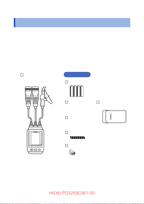
Conrm that these contents are provided.
Model PD3259-50
Digital Phase Detector
2
Accessories
LR6 Alkaline batteries ×4
Instruction
manual
(This document)
Operating
Precautions
(0990A907)
Spiral tubes (black)
Color clips (white, red, blue, yellow)
×2 (each color)
Model C0203
Carrying Case
Page 9
Options (Sold Separately)
HIOKI PD3259C961-00
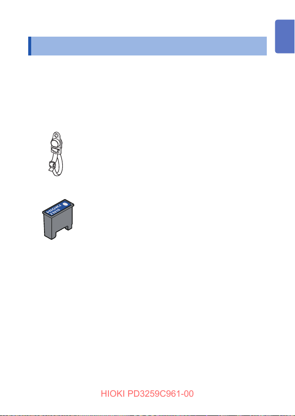
Options (Sold Separately)
The options listed below are available for the instrument. To order
an option, please contact your authorized Hioki distributor or
reseller.
Options are subject to change. Please check Hioki’s website for the
latest information.
Model Z5020 Magnetic Strap (p. 23)
Using this strap lets you attach the instrument on a wall,
such as a metal surface.
Model Z3210 Wireless Adapter (p. 28)
Installing the Z3210 to the instrument lets you receive and
send data wirelessly.
See “3.11 Wireless communications function” (p. 52).
3
Page 10

Safety Information
HIOKI PD3259C961-00
Safety Information
This instrument is designed to conform to IEC 61010 Safety
Standards, and has been thoroughly tested for safety prior to
shipment. However, using the instrument in a way not described in
this manual may negate the provided safety features.
Carefully read the following safety notes before using the
instrument.
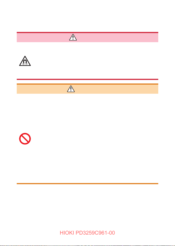
CAUTION
• Mishandling during use could damage to the
instrument. Familiarize yourself with the instructions and
precautions in this manual before use.
• If you have not used any electrical measuring
instruments before, you should be supervised
by a technician who has experience in electrical
measurement.
Protective gear
WARNING
Performing measurement using this instrument
involves live-line work. To prevent an electric shock,
use appropriate protective insulation and adhere to
applicable laws and regulations.
4
Page 11
Safety Information
HIOKI PD3259C961-00
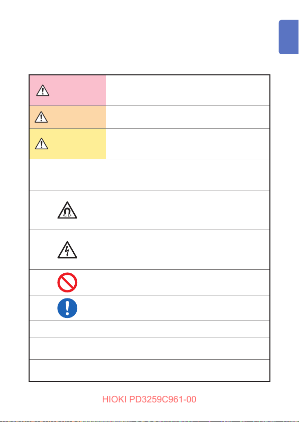
Notations
In this document, the severity levels of risk and hazard are classied
as follows.
Indicates an imminently hazardous situation
DANGER
WARNING
CAUTION
IMPORTANT
that will result in death of or serious injury to the
operator.
Indicates a potentially hazardous situation that may
result in death of or serious injury to the operator.
Indicates a potentially hazardous situation that may
result in minor or moderate injury to the operator or
damage to the instrument or malfunction.
Indicates information or content that is particularly
important from the standpoint of operating or
maintaining the instrument.
Indicates a strong magnetic-eld hazard.
The eects of the magnetic force can cause
abnormal operation of heart pacemakers and/or
medical electronics.
Indicates a high-voltage hazard.
Failure to verify safety or improper handling of the
instrument could lead to an electric shock, burn, or
death.
Indicates an action that must not be performed.
Indicates the action that must be performed.
*
[ ]
HOLD
(Boldface)
Indicates additional information is described below.
Names of user interface elements on the screen
are enclosed in brackets (
Alphanumeric characters shown in bold indicate
the characters that appear on the control keys.
[ ]).
5
Page 12
Safety Information
HIOKI PD3259C961-00
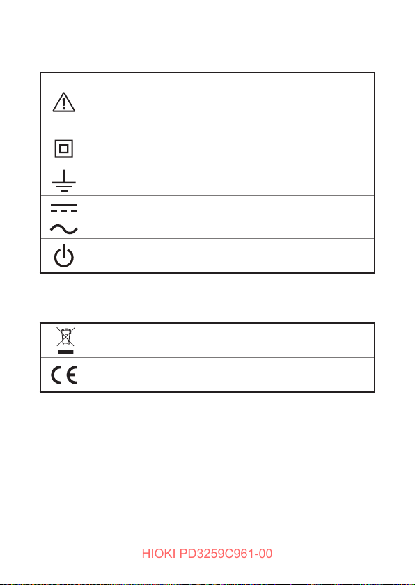
Symbols on the instrument
Indicates the presence of a potential hazard. For more
information about locations where this symbol appears on
the instrument components, see a corresponding topic in the
Instruction Manual.
Indicates an instrument that has been protected throughout by
double insulation or reinforced insulation.
Indicates the grounding terminal.
Indicates DC (Direct current).
Indicates AC (Alternating current).
Indicates the power button that switches the instrument
between on and o states.
Symbols for various standards
Indicates the Waste Electrical and Electronic Equipment
Directive (WEEE Directive) in EU member states.
Indicates that the product complies with standards imposed by
EU directives.
6
Page 13
Safety Information
HIOKI PD3259C961-00
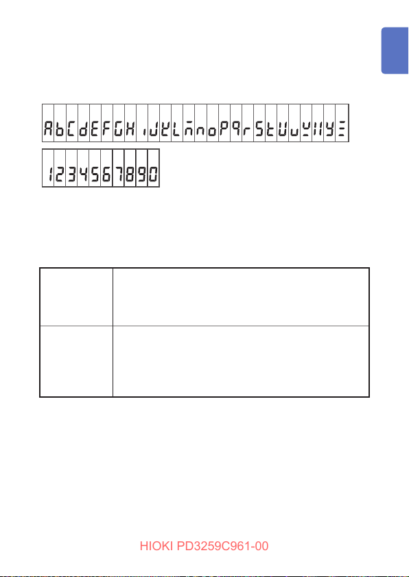
Segments on the screen
The screen of this instrument displays characters in the following
manner.
A B C D E F G H I J K L M N O P Q R S T U V W X Y Z
1 2 3 4 5 6 7 8 9 0
Accuracy
Hioki expresses accuracy as error limit values specied in terms of
percentages of reading and digits.
Reading
(Displayed
value)
Digit
(Resolution)
Refers to the displayed value of the measuring
instrument.
The limit values of reading errors are expressed in
percent of reading (% of reading, % rdg).
Refers to the smallest change in the indication on the
digital measuring instrument, i.e., the numeral one in the
rightmost place.
The limit values of digit errors are expressed in terms of
digits (dgt).
7
Page 14
Safety Information
HIOKI PD3259C961-00
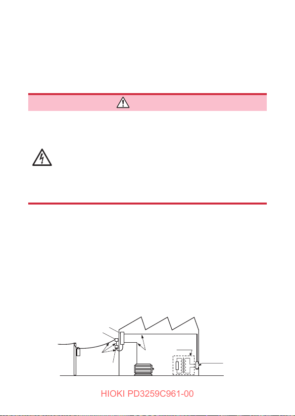
Measurement categories
To ensure safe operation of measuring instruments, IEC 61010
species the measurement categories,which classies testing and
measuring circuits into three categories according to the types of
mains circuits to which they are intended to be connected.
DANGER
• Do not use a measuring instrument for
measurements on a mains circuit that exceeds the
range of the measurement category rated for the
instrument. Failure to observe this can cause a
severe accident.
• Do not use a measuring instrument without a
measurement category rating for measurements on
a mains circuit. Failure to observe this can cause a
severe accident.
This instrument conforms to the safety requirements for CAT IV 600 V
measuring instruments.
CAT II: Applicable to test and measuring circuits connected directly to
CAT III: Applicable to test and measuring circuits connected to the
CAT IV: Applicable to test and measuring circuits connected at the source of
utilization points (socket outlets and similar points) of the lowvoltage mains installation.
distribution part of the building’s low-voltage mains installation.
the building’s low-voltage mains installation.
Distribution panel
Service entrance
Service drop
CAT IV
Power meter
8
Internal wiring
CAT III
Fixed installation
CAT II
T
Outlet
Page 15
Operating Precautions
HIOKI PD3259C961-00
Operating Precautions
Observe the following precautionary information to ensure that the
instrument can be used safely and in a manner that allows it to
perform as described in its specications.
Use of the instrument should conrm not only to its specications,
but also to the specications of all accessories, options, batteries,
and other equipment in use.
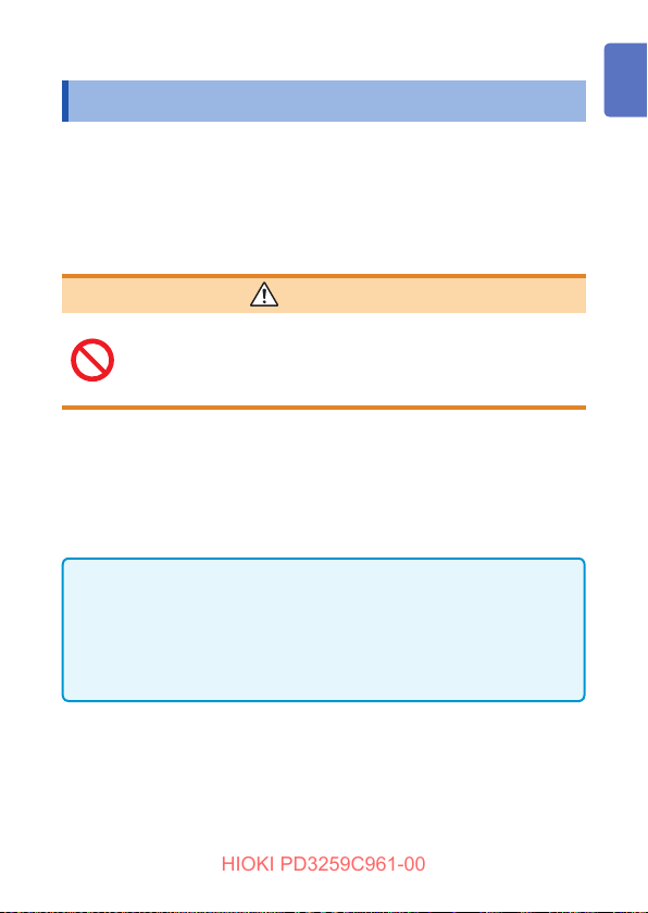
WARNING
Do not use the instrument to measure circuits that
exceed its ratings or specications.
Damage to the instrument can cause an electric
shock.
Check the instrument for any damage that may have occurred
during storage or shipping, and perform functional checks before
use.
If you nd any damage, contact your authorized Hioki distributor or
reseller.
This instrument complies with EN 61326 Class A.
This instrument may cause interference if used in residential
areas.
Such use must be avoided unless the user takes special
measures to reduce electromagnetic emissions to prevent
interference to the reception of radio and television broadcasts.
9
Page 16
Operating Precautions
HIOKI PD3259C961-00
Installation
Individuals with electronic medical devices such as a
pacemaker must not use the Z5020 Magnetic Strap.
Such individuals must avoid even proximity to
theZ5020 Magnetic Strap, as it could be dangerous.
Medical device operation could be compromised,
presenting a hazard to human life.
Installing the instrument in inappropriate locations
could cause a malfunction of the instrument or an
accident.
Avoid locations that are:
• Exposed to direct sunlight or high temperature
• Exposed to corrosive or combustible gases
• Exposed to strong electromagnetic elds or
electrostatic charges
• Near induction heating systems (such as high-
frequency induction heating systems and IH
cooking equipment)
• Susceptible to vibration
• Exposed to water, oil, chemicals, or solvents
• Exposed to high humidity or condensation
• Exposed to high concentrations of dust particles
DANGER
WARNING
10
Page 17

Operating Precautions
HIOKI PD3259C961-00
Handling of the instrument
DANGER
To prevent an electric shock, do not touch any areas
beyond the barrier while the instrument is in use.
CAUTION
To avoid damage to the instrument, do not subject it to
vibration or mechanical shock during transportation and
handling. Exercise particular care to avoid subjecting the
instrument to mechanical shock, for example by dropping.
Turn o the instrument after use.
Handling the voltage sensors
IMPORTANT
If the target to be measured is an insulated cable with dirt or moisture
on its insulation, the instrument may read lower values than the actual
voltage. In this case, wipe it clean with a dry cloth before measurement.
Failure to do so may could cause inaccurate measurement, in particular, if
the measurement is performed with multi-conductor, heavily insulated, or
dirty cables.
11
Page 18
Operating Precautions
HIOKI PD3259C961-00
Handling of the cables
WARNING
To prevent an electric shock, check that the inside of
the cable is not exposed. If any color is visible from
the inside of the cable, do not use the instrument.
CAUTION
• Avoid stepping on or pinching cables, which could
damage the cables insulation.
• To prevent damage due to snapped wires, do not bend
or pull the base of the voltage sensor or cables.
The cable is hardened in freezing temperatures. Do not
bend or pull it to avoid tearing its shield or breaking cables.
Precautions when transporting the instrument
CAUTION
During shipment of the instrument, handle it carefully so
that it is not damaged due to a vibration or shock.
12
Page 19

Overview
HIOKI PD3259C961-00
1
1.1 Overview and Features
The PD3259 is a phase detector with an integrated voltmeter that
can measure line-to-line voltages, check phase sequence, measure
frequency, and check for live cables and the grounding phase in
three-phase circuits.
Thanks to no-metal-contact voltage measurement technology,
you can measure voltage by just axing the voltage sensors to
cables, facilitating safe working conditions. In addition, because the
instrument lets you measure line-to-line voltages, verify that cables
are live, and check phase voltages and the grounding phase at
once, it will eliminate wiring errors and reduce work times.
By installing the Z3210 Wireless Adapter (optional) in the instrument,
you can log measured data acquired through the instrument and
create measurement reports with your mobile communications
devices.
13
Page 20

Overview and Features
HIOKI PD3259C961-00
Three-phase line-to-line voltage
measurement
Measures line-to-line voltages in a threephase circuit from outside the cable
insulation (without any metal contact).
Frequency measurement
Open-phase prediction function
Phase detection function
Determines whether the threephase circuit has positive
or negative (reverse) phase
sequence.
Hold function
Freezes the measured values
and phase detection result shown
on the display.
14
Page 21
Part Names and Functions
HIOKI PD3259C961-00
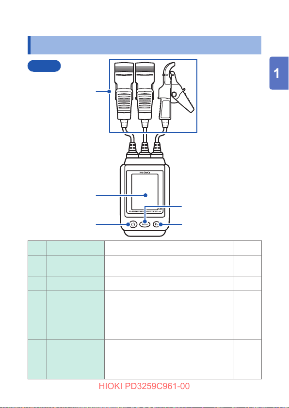
1.2 Part Names and Functions
Front
1
2
4
Voltage sensors Detect voltage. p. 34
1
Display
2
Power key Turns on/o the instrument. –
3
HOLD key
4
Fn key
5
3
Shows measured values and judgment
results.
Freezes the judgment result and
measured values shown on the display.
Simultaneously pressing and holding the
HOLD and Fn keys toggles the wireless
communications function on and o.
Switches over the screen and function.
Simultaneously pressing and holding the
HOLD and Fn keys toggles the wireless
communications function on and o.
5
p. 18
p. 50
p. 52
p. 33
p. 52
15
Page 22
Part Names and Functions
HIOKI PD3259C961-00
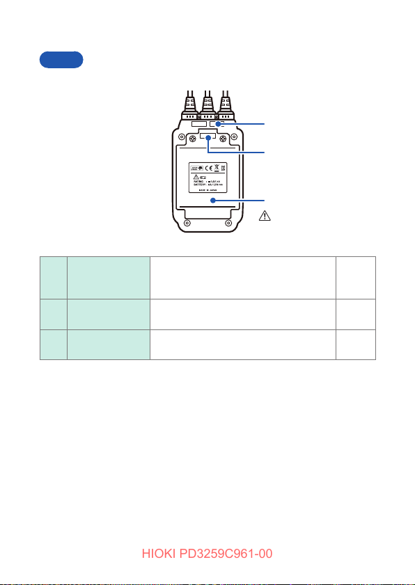
Rear
6
7
8
(p. 24)
Serial number
6
label
Strap slot
7
Battery cover
8
16
The 9-digit serial number indicates the
year (rst two digits) and the month of
manufacture (next two digits).
Attach the Z5020 Magnetic Strap
(optional) here.
Remove the cover when replacing the
batteries.
p. 49
p. 23
p. 24
Page 23
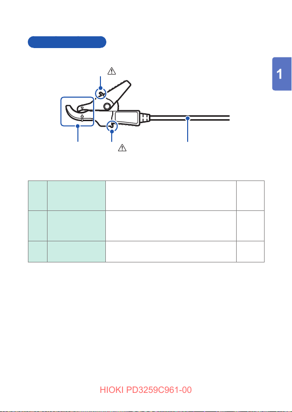
Voltage sensors
HIOKI PD3259C961-00
(p. 11)
9
(p. 11)
910 11
Part Names and Functions
Barriers
9
Clips
10
Cables
11
To prevent an electric shock, do not
touch any areas beyond the barrier while
the instrument is in use.
Ax the clips to each insulated cable to
be measured so that the mark points to
the cable.
You can attach the color clips, which
came with the instrument, here.
p. 34
p. 34
p. 22
17
Page 24
Part Names and Functions
HIOKI PD3259C961-00
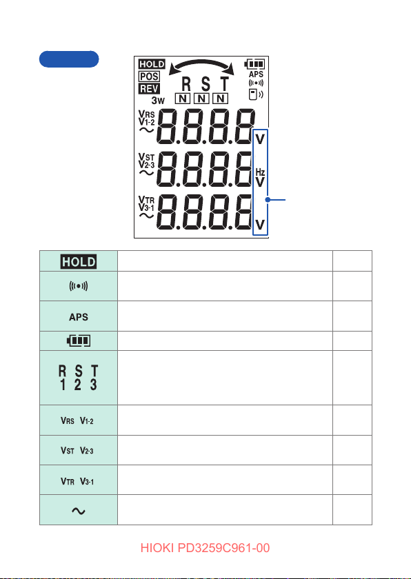
Display
Units of measure
( )
( )
( )
( )
18
Indicates that the hold function is enabled.
Indicates that the beeping sound setting for the
phase detection function is enabled.
Indicates that the auto-power save function is
enabled.
Indicates the remaining battery level.
Indicates phases. The screen mode can be
switched.
If an open phase is suggested, the indicator for
corresponding phase will be hidden.
Indicates that the line-to-line voltage V
displayed.
Indicates that the line-to-line voltage V
displayed.
Indicates that the line-to-line voltage V
displayed.
(V
) is
RS
1-2
(V
) is
ST
2-3
(V
) is
TR
3-1
Indicates the circuit under measurement carries
AC (alternating current).
p. 50
p. 39
p. 45
p. 26
p. 42
p. 47
p. 37
p. 37
p. 37
–
Page 25

Part Names and Functions
HIOKI PD3259C961-00
Indicates that the phase detection function
determines the circuit has a positive phase
sequence.
Indicates that the phase detection function
determines the circuit has a negative (reverse)
phase sequence.
Indicates that the phase is predicted to be the
grounding phase.
Indicates whether the circuit has positive or
negative (reverse) phase sequence using the
arrow direction.
Indicates the measurement target is a threephase three-wire circuit.
Indicates the status of the wireless
communications.
p. 39
p. 39
p. 42
p. 39
–
p. 52
19
Page 26

Part Names and Functions
HIOKI PD3259C961-00
20
Page 27

Preparing for Measurement
HIOKI PD3259C961-00
2
2.1 Measurement Procedure
Before using the instrument, be sure to read “Operating
Precautions” (p. 9).
Setting up, connecting, and turning on the instrument
Insert the batteries. (p. 24)
Inspect the instrument before use. (p. 30)
Arrange to use other
Turn on the instrument. (p. 15)
Ax the voltage sensors. (p. 34)
Performing measurement
Perform measurement. (p. 33)
• Measuring line-to-line voltages in a three-phase circuit (p. 37)
• Checking phase sequence in a three-phase circuit (phase sequence
detection) (p. 39)
• Measuring the frequency (p. 41)
Freeze the measured values and phase
sequence judgment result shown on the
display. (p. 50)
options as needed.
Finishing measurement
Turn o the instrument. (p. 15)
21
Page 28

Attaching the Color Clips
HIOKI PD3259C961-00
2.2 Attaching the Color Clips
Attach the accompanying color clips and spiral tubes as needed.
Attaching the color clips (white, red, blue, and yellow) to make the
voltage sensors distinguishable from each other.
Color-code the sensors according to the three-phase labeling
system of your country or region.
You can bind cables together using the spiral tubes.
Attach the clips with the same color on the clip side and
1
the instrument side of each cable.
Bind cables together using the spiral tubes.
2
1
1
2
22
Page 29

Attaching the Strap
HIOKI PD3259C961-00
2.3 Attaching the Strap
Attaching the Z5020 Magnetic Strap (optional), which is equipped
with a magnet, to the instrument lets you attach the instrument on a
steel plate or wall surfaces.
Model Z5020
Rear
Strap slot
Model Z5020
Magnet
Front
Rear
23
Page 30

Installing/Replacing Batteries
HIOKI PD3259C961-00
2.4 Installing/Replacing Batteries
When using the instrument, insert four LR6 Alkaline batteries.
Verify that sucient battery power remains before measurement.
If the batteries are exhausted (p. 26), replace the batteries with
fresh ones.
WARNING
• To avoid an electric shock, turn o the instrument
and remove the voltage sensors from the target
under measurement before replacing the batteries.
Do not short-circuit, recharge, disassemble the
batteries, or dispose of them in re. Batteries may
explode if mistreated.
To prevent instrument damage or an electric shock,
use only the screws that are originally installed for
securing the battery cover in place. (M3 × 8 mm)
If you have lost any screws or nd that any screws
are damaged, please contact your authorized Hioki
distributor or reseller for a replacement.
24
Page 31

Installing/Replacing Batteries
HIOKI PD3259C961-00
CAUTION
Poor performance or damage from battery leakage could
result.
• Do not mix old and fresh batteries, or dierent types of
batteries.
• Pay attention to the polarity markings, “+” and “−,”
so that you do not insert the batteries the wrong way
around.
• Do not use batteries after their recommended expiry
dates.
• Do not leave a depleted battery inside the instrument.
• Replace batteries only with the specied type of ones.
• Remove the batteries from the instrument if it is to be
stored for a long time.
• Handle and dispose of batteries in accordance with local
regulations.
• When the batteries are exhausted, the symbols will blink.
In this case, the accuracy of any values are not guaranteed.
Thus, replace the batteries with fresh ones as soon as possible.
25
Page 32

Installing/Replacing Batteries
HIOKI PD3259C961-00
Battery indicator
Batteries partially discharged.
The graduations in the indicator disappear from the left as the
battery’s power falls.
Low batteries.
Keep fresh batteries handy.
Blinking
The batteries have run out. Replace the batteries with fresh
ones immediately.
If you continue to use, the instrument can be unexpectedly
shut down.
Measurement accuracy cannot be guaranteed in this state.
The battery indicator provides a rough guideline of how much continuous
operating time remains.
Shutdown
26
When the indicator shows no remaining
battery power (the
[bAtt Lo] will be shown for 2 s, and the
string
instrument will shut down.
icon is blinking), the
Page 33

Installing/Replacing Batteries
HIOKI PD3259C961-00
Installing/replacing batteries
You will need:
• Phillips-head screwdriver (No. 2)
• LR6 Alkaline batteries ×4
Remove the voltage sensors from the target under
1
measurement and turn o the instrument.
Loosen the screws that holds the battery cover in place with
2
the screwdriver and remove the cover.
If replacing the batteries, remove all old batteries.
3
Insert four fresh batteries, observing the polarity markings.
4
Reattach the battery cover and tighten the screws.
5
Battery cover
M3 × 8 mm
Screws
Batteries
Do not remove the protective cover (p. 29) on the Z3210 insertion slot.
Doing so could impair the dust-proofness and water-proofness.
Rear
27
Page 34

Installing the Z3210 Wireless Adapter
HIOKI PD3259C961-00
2.5
Installing the Z3210 Wireless Adapter
By installing the Z3210 Wireless Adapter (optional) in the
instrument, you can wirelessly log measured data acquired through
the instrument and create measurement reports with your mobile
communications devices.
See “3.11 Wireless communications function” (p. 52).
WARNING
• To avoid an electric shock, turn o the instrument
and remove the voltage sensors from the target
under measurement before installing the Z3210.
• After installing the Z3210, reattach the protective
cover and battery cover and secure the screws
before using the instrument.
• To prevent instrument damage or an electric shock,
use only the screws that are originally installed for
securing the battery cover in place. If you have lost
any screws or nd that any screws are damaged,
please contact your authorized Hioki distributor or
reseller for a replacement.
CAUTION
After touching any metallic part, such as a doorknob,
to eliminate static electricity from your body, connect/
disconnect the Z3210. Failure to do so could cause static
electricity to damage the Z3210.
28
Page 35

Installing the Z3210 Wireless Adapter
HIOKI PD3259C961-00
Installing/replacing the Z3210
You will need:
• Phillips-head screwdriver (No. 2)
• Model Z3210 Wireless Adapter
Remove the voltage sensors from the target under
1
measurement and turn o the instrument.
Loosen the screws that holds the battery cover in place with
2
the screwdriver and remove the cover.
Remove the protective cover from the Z3210 insertion slot.
3
Install the Z3210, observing the correct orientation, as far
4
as it will go.
Attach the protective cover into the Z3210 insertion slot.
5
Reattach the battery cover and tighten the screws.
6
Screws
M3 × 8 mm
To maintain the dust-proofness and water-proofness, put the protective
cover on the Z3210 insertion slot regardless of the presence or absence of
the Z3210.
Battery cover
Model Z3210
Protective cover
Z3210 insertion slot
Rear
29
Page 36

Inspecting the Instrument
HIOKI PD3259C961-00
2.6 Inspecting the Instrument
Check the instrument for any damage that may have occurred
during storage or shipping, and perform functional checks before
use. If you nd any damage, contact your authorized Hioki
distributor or reseller.
Checking item Action
Does an error code
appear on the display?
Are there any cracks or
other damage?
Is the cables’ insulation
damaged, or is any metal
exposed?
Are the batteries
exhausted?
Does the display show
something at the time of
power-on?
When an error code appears, see “Errors and
status codes” (p. 67) to identify the error.
The instrument’s insulation may have been
compromised. Avoid using the instrument and
have it repaired. Failure to do so could cause an
electric shock.
If there is any damage, avoid using the
instrument and have it repaired. Failure to do so
could cause an electric shock.
If there is insucient battery power remaining,
replace the batteries with fresh ones. (p. 24)
If nothing is showing up, replace the batteries
with fresh ones and check again. (p. 24)
30
Page 37

Checking item Action
HIOKI PD3259C961-00
Does the display show
the string “Pd3259” and
a startup animation at the
time of power-on?
When the screen switches over from the power-
on screen (the string “Pd3259” and the startup
animation) to the measurement screen, the
instrument operates normally. When an error
code appears, see “Errors and status codes”
(p. 67) to identify the error.
Inspecting the Instrument
Power-on screen
Pd3259
Startup animation
31
Page 38

Inspecting the Instrument
HIOKI PD3259C961-00
32
Page 39

Performing Measurement
HIOKI PD3259C961-00
3
3.1 Switching the Screen Mode
When you press the
Turn on the instrument.
Line-to-line voltage
measurement screen
(p. 37)
Phase detection screen
(p. 39)
Frequency measurement
screen (p. 41)
Return to the line-to-line
voltage measurement
screen.
Fn key, the screen mode will switch over.
Press and hold
Phase voltage
measurement screen
(p. 38)
Press and hold
Phase voltage
measurement screen
(p. 38)
33
Page 40

How to Use Voltage Sensors
HIOKI PD3259C961-00
3.2 How to Use Voltage Sensors
How to ax the voltage sensors properly
Ax each sensor to an insulated cable to be measured so that the mark
points to the cable. The sensor can be axed to a cable with diameters
ranging from 6 mm to 30 mm.
DANGER
To prevent an electric shock, do not touch any areas
beyond the barrier while the instrument is in use.
Example: For thick insulated cables
Insulated cable
Mark
Insulated cable
Barrier
Barrier
Example: For thin insulated wires
Insulated cable
Mark
Insulated cable
Marks
Insulated cable
Mark
Insulated cable
Mark
Barrier
34
Barrier
Marks
Page 41

How to Use Voltage Sensors
HIOKI PD3259C961-00
Improperly axed sensor
A voltage sensor axed improperly will be susceptible to eects of nearby
cables, resulting in inaccurate measurement.
The insulated cable is pinched
by the tips of the clip.
Insulated cable
The sensor is axed to the
insulated cable at an angle.
Insulated cable
The insulated cable is inserted
too close to the pivot point.
IMPORTANT
If an insulated cables under measurement are dirt or wet, the instrument
may display values lower than the actual voltages. In this case, wipe them
clean with a dry cloth before measurement.
Insulated cable
The sensor is axed to two
insulated cables together, each of
which carries a voltage dierent
from each other.
Insulated cable
35
Page 42

Axing the Voltage Sensors
HIOKI PD3259C961-00
3.3 Axing the Voltage Sensors
Ax the voltage sensors R (1), S (2), and T (3) to the cables respectively of
phase R (1), S (2), and T (3).
R S T
(1)(2) (3)
R S T
(1)(2) (3)
RRTTSS
(1)(2) (3)
(1)(2) (3)
RRTTSS
(1)(2) (3)
(1)(2) (3)
Measurement using the Model Z5020
Magnetic Strap
Measurement with
the instrument in your
hand
Phase labeling systems
Many labeling systems exist for three-phase systems.
<Examples>
First phase Second phase Third phase
R S T
L1 L2 L3
A B C
U V W
Ax voltage sensors R (1), S (2), and T (3) respectively to the rst, second,
and third phases of the three-phase circuit.
36
Page 43

Measuring Line-to-Line Voltages in a Three-Phase Circuit
HIOKI PD3259C961-00
3.4 Measuring Line-to-Line Voltages in a Three-Phase Circuit
Three-phase line-to-line voltage measurement
The display will show voltages; V
V
).
3-1
When measuring a three-phase circuit, the display will show the
three line-to-line voltage values.
, VST, and VTR (or V
RS
Display the line-to-line voltage
1
, V
, and
1-2
2-3
measurement screen.
The line-to-line voltage measurement screen
is displayed rst at the time of the start-up.
When you wish to display the phase detection
screen, press the
Check the measured values.
2
If the line-to-line voltage is less than 30.0 V,
the string
voltage exceeds 600.0 V, the string
will be shown.
Fn key.
[Lo] will be shown; if the line-to-line
[ovEr]
The instrument can measure line-to-line voltage between any two
voltage sensors axed to a circuit other than the three-phase
system.
37
Page 44

Measuring Line-to-Line Voltages in a Three-Phase Circuit
HIOKI PD3259C961-00
Phase voltage measurement (values for reference purposes)
The display will show V
, VS, and VT (or V1, V2, and V3).
R
When measuring a three-phase circuit, the display will show the
three phase voltage values. However, since the neutral line cannot
be measured, the displayed values indicate a line-to-ground
voltage of each phase using the virtual neutral point (ground) as the
reference.
The displayed phase voltages, accuracy of which is not
guaranteed, can be used for reference only.
Display the line-to-line voltage
1
measurement screen.
The line-to-line voltage measurement screen
is displayed rst at the time of the start-up.
Press and hold the Fn key.
2
Press and hold
38
The phase voltage measurement screen will
be displayed.
Check the displayed values.
3
If the phase voltage is less than 30.0 V, the
string
[Lo] will be shown; if the phase voltage
exceeds 400.0 V, the string
shown.
Press the Fn key.
4
The line-to-line voltage measurement screen
will be displayed.
[ovEr] will be
Page 45

Checking the Phase Sequence in a Three-Phase Circuit (Phase Detection Function)
HIOKI PD3259C961-00
3.5 Checking the Phase Sequence in a Three-Phase Circuit (Phase Detection Function)
The instrument displays the phase detection result when measuring
a three-phase circuit.
The display will be backlit and the instrument will emit beeping
sounds to indicate the phase detection result.
However, the instrument will emit no sound if the beeping sound
setting is disabled. (p. 48)
Display the phase detection
1
screen. (p. 33)
Check the phase detection
2
screen.
When the circuit has positive phase sequence
Yellow
green
intermittent
The display will show the following icons:
, , and .
The display will be backlit in yellow green,
and the instrument will emit a series of
short beeping sounds.
39
Page 46

Checking the Phase Sequence in a Three-Phase Circuit (Phase Detection Function)
HIOKI PD3259C961-00
When the circuit has negative (reverse) phase sequence
The display will show the following icons:
Red
Continuous
, , and .
The display will be backlit in red, and the
instrument will emit a continuous beeping
sound.
(The instrument will automatically stop
beeping sounds after 10 s or once the hold
function is enabled.)
If the instrument fails to detect phase
sequence, the
arrow will not appear.
Press the Fn key twice.
3
POS or REV icon or any
Press twice
40
The line-to-line voltage measurement
screen will be displayed.
Page 47

Measuring the frequency
HIOKI PD3259C961-00
3.6 Measuring the frequency
The instrument will measure the frequency of the line-to-line voltage
VRS.
Display the frequency
1
measurement screen. (p. 33)
Check the measured value. (The
2
frequency of the line-to-line
voltage VRS will be displayed.)
When the measured frequency is less than
45.0 Hz, the string
frequency exceeds 66.0 Hz, the string
will be shown.
Press the Fn key.
3
The line-to-line voltage measurement screen
will be displayed.
During frequency measurement, only the frequency of the line-toline voltage VRS is measured.
The instrument measures the frequency of the dierential signal
acquired between voltage sensors R (1) and S (2).
[Lo] will be shown; if the
[ovEr]
41
Page 48

Displaying the Predicted Three-Phase Circuit Status
HIOKI PD3259C961-00
3.7 Displaying the Predicted Three-Phase Circuit Status
When measuring a three-phase delta-wired circuit with one phase
grounded, the PD3259 can automatically predict the grounding
phase.
In addition, the instrument can predict whether the three-phase
circuit has an open phase.
The results are shown using icons on the display.
These functions are available only in Japan.
Grounding phase prediction
If phase S is grounded, the
be shown underneath the
Similarly, if phase R is grounded, the
icon will be shown underneath the
icon; if the phase T is grounded, the
icon will be shown underneath the
icon.
(The similar display manner is used for
the phase labeling system with 1, 2, and
3.)
Open-phase prediction
If the instrument predicts that the threephase circuit has an open phase, the
icon corresponding to that among the
icons (or the icons) will be
hidden.
icon will
icon.
Proper identication of the grounding phase or open phase is not
guaranteed for these predictions.
circuit incorporates complex wiring or if the distance between the
measurement point and a wire break point meets certain criteria.
42
Results may be inaccurate if the
Page 49

Power-On Options
HIOKI PD3259C961-00
3.8 Power-On Options
Use the keys at the time of start-up to congure the following
settings:
• Auto-power save function
• Phase display switching function
• Beeping sound setting
• Firmware version number and serial numbers display
Turn on the instrument while holding
down the
Auto-power save function (p. 45)
Power-on screen
HOLD key.
Turn on the instrument while
holding down the Fn key.
Phase display switching function
(p. 47)
Beeping sound setting (p. 48)
Power-on screen
43
Page 50

Power-On Options
HIOKI PD3259C961-00
Turn on the instrument while holding down the
HOLD and Fn keys.
Firmware version information (p. 49)
Serial number (p. 49)
Power-on screen
44
Page 51

Power-On Options
HIOKI PD3259C961-00
Auto-power save function
The instrument provides functionality for limiting battery
consumption.
When the auto-power save function is enabled, the instrument will
be automatically turned o after 10 minutes of inactivity.
(The instrument will emit a series of short beeping sounds starting
30 s before the power-o.)
The [APS] icon will be displayed.
(Indicating that auto-power save is
enabled)
The auto-power save function will be enabled when the instrument
is normally turned on.
This section describes how to disable the auto-power save function.
(p. 46)
45
Page 52

Power-On Options
HIOKI PD3259C961-00
Disabling the auto-power save function
You can set the auto-power save function disabled.
Turn on the instrument while holding
down the HOLD key.
The string [APS oFF] will be shown.
The power-on screen will be
displayed.
46
The [APS] icon will be turned o.
(Indicating that auto-power save is
disabled)
Page 53

Power-On Options
HIOKI PD3259C961-00
Switching the phase display (Phase display
switching function)
This section describes how to choose between two phase labeling
systems, one using “
Phase display
Line-to-line voltage
display
” and one using “ ”.
” “ ”
“
, , , ,
Turn on the instrument while
1
holding down the Fn key.
Press the HOLD key to choose the
2
phase labeling system.
[rst] ↔ [123]
Press the Fn key.
3
The phase display switching function setting will be saved and
also applied at the next startup of the instrument.
Press the Fn key again.
4
After the power-on screen is displayed, the
line-to-line voltage measurement screen will
be displayed.
47
Page 54

Power-On Options
HIOKI PD3259C961-00
Beeping sound setting
This section describes how to enable and disable the beeping
sound setting.
You can set the instrument so that it emits beeping sounds when
keys are pressed and the phase sequence is determined.
Turn on the instrument while
1
holding down the Fn key.
Press the Fn key.
2
Press HOLD to choose whether
3
to enable or disable the beeping
sound setting.
[on]↔[oFF]
Press the Fn key.
4
The beeping sound setting will be saved and also applied at the
next startup of the instrument.
48
After the power-on screen is displayed, the
line-to-line voltage measurement screen will
be displayed.
Page 55

Power-On Options
HIOKI PD3259C961-00
Checking the rmware version information and
serial number
This section describes how to display rmware version information
along with the instrument’s serial number.
Turn on the instrument while
1
holding down both the HOLD
and Fn keys.
The string [vEr] will be displayed.
Press the Fn key.
2
Check the serial number.
3
Example: Serial number 201200001
The serial number consists of nine digits.
The rst two (from the left) indicate the year
of manufacture, and the next two indicate
the month of manufacture.
Press the Fn key.
4
After the power-on screen is displayed, the
line-to-line voltage measurement screen will
be displayed.
49
Page 56

Hold function
HIOKI PD3259C961-00
3.9 Hold function
This section describes how to freeze measured values and phase
detection results shown on the display.
The hold function can be used on the voltage measurement screen,
phase detection screen, and frequency measurement screen.
Setting the hold function
Press HOLD to choose whether to
enable or disable the hold function.
When the [HOLD] icon is hidden
(during normal operation):
The hold function is disabled.
When the [HOLD] icon is shown:
The hold function is enabled.
(The display will freeze the measured
values and judgment results.)
When the instrument determines that the circuit has positive
phase sequence or when it fails to detect phase sequence,
the display will be backlit in green yellow. When the instrument
determined that the circuit has negative (reverse) phase
sequence, the display will be backlit in red.
50
Page 57

Backlight function
HIOKI PD3259C961-00
3.10 Backlight function
This section describes how to turn on the backlight.
The backlight makes it possible to observe the display clearly in dim
locations where the LCD would otherwise be dicult to see.
Enabling the backlight function
Pressing and holding the HOLD key to
choose whether to enable or disable the
backlight function.
Press and hold
Yellow green
Ordinarily the display will be backlit in
yellow green; however, it will be backlit
in red when the instrument determines
that the circuit has negative (reverse)
phase sequence. (p. 39)
The backlight will be automatically turned
o after 30 s regardless of the hold function
setting or screen switching.
However, when the phase detection
screen shows a phase detection result, the
backlight will change in color depending of
the phase detection result after 30 s has
elapsed.
51
Page 58

Wireless communications function
HIOKI PD3259C961-00
3.11 Wireless communications function
Using GENNECT Cross
Enabling the wireless communications function lets you check
measured data acquired through the instrument and create
measurement reports with your mobile communications devices.
The Z3210 Wireless Adapter is required to use this function.
For details, see the Help function in GENNECT Cross (free-of-charge
application).
GENNECT Cross Special Site
https://gennect.net/en/cross/index
52
Page 59

Blinking: While sending
HIOKI PD3259C961-00
and receiving data
wirelessly
On: Communications
function enabled
O: Communications
function disabled
Simultaneously pressing
and holding the
and
Fn keys toggles the
wireless communications
function on and o.
HOLD
Wireless communications function
Connect the Z3210 Wireless
1
Adapter into the instrument.
(p. 28)
Install GENNECT Cross onto
2
your mobile communications
device.
Turn on the instrument.
3
Press and hold the HOLD
4
and Fn keys simultaneously
to turn on the wireless
communications function.
The display will show the
Start GENNECT Cross and
5
register the instrument to
connect.
Select each function and
6
perform measurement.
icon.
53
Page 60

Wireless communications function
HIOKI PD3259C961-00
• The communications distance is about 10 m with a clear line of
sight. The communicable distance may vary greatly depending on
the presence of an obstruction (wall or metallic shielding object)
and the distance between the oor (ground) and instrument. To
ensure the stable communications, make sure that the radio wave
intensity is sucient.
• GENNECT Cross is free of charge; however, the customer is
responsible for the cost to download the application software and
connect to the Internet when using the software.
• Some mobile communications devices cannot operate GENNECT
Cross.
• The Z3210 uses the 2.4 GHz band wireless technology.
When there is a device that uses the same frequency band
such as a wireless LAN (IEEE802.11.b/g/n) near your mobile
communications device, the communications may not be
established.
• When starting for the rst time, GENNECT Cross will display the
connection setting screen.
• GENNECT Cross with the connection setting screen shown will
automatically register up to eight measuring instruments when
they are located nearby.
• Leave the instrument for 5 s to 30 s after power up until the
instrument is registered for connection. If no registration has
completed after one minute has elapsed, restart GENNECT
Cross and the instrument.
• When you turn on the instrument for the rst time after
installing the Z3210, the instrument will start with the wireless
communications function enabled. The setting will be retained
even after power o.
54
Page 61

Wireless communications function
HIOKI PD3259C961-00
• Even when the Z3210 has been connected, GENNECT Cross
or the Z3210’s direct input function cannot acquire any phase
voltages. (p. 38)
• When the Z3210 has been connected, GENNECT Cross and
the Z3210’s direct input function can acquire unbalanced voltage
ratios.
U
umb
(Negative sequence voltage)
(%) = × 100
(Positive sequence voltage)
55
Page 62

Wireless communications function
HIOKI PD3259C961-00
Useful functionality of the Z3210
For detail information, please visit the Z3210’s website.
https://z3210.gennect.net
56
Page 63

Specications
HIOKI PD3259C961-00
4
4.1 General Specications
Operating
environment
Operating
temperature and
humidity
Storage temperature
and humidity
Dust-proofness,
water-proofness
Standards Safety: EN 61010
Power supply LR6 Alkaline batteries ×4
Continuous
operating time
Dimensions Main body: Approx. 84W × 146H × 46D mm
Cable length Approx. 0.5 m
Mass Approx. 590 g (20.8 oz., including batteries)
Product warranty
period
Indoors, pollution degree 2, altitude up to 2000 m
(6562 ft.)
−25°C to 50°C (−13°F to 122°F), 80% RH or less
(no condensation)
50°C to 65°C (122°F to 149°F), 50% RH or less
(no condensation)
−25°C to 65°C (−13°F to 149°F), 80% RH or less
(no condensation)
Main body (excluding voltage sensors):
IP54 (EN 60529)
EMC: EN 61326 Class A
Rated supply voltage: 1.5 V DC × 4
Maximum rated power: 3 VA
When using LR6 Alkaline batteries ×4
(value for reference purposes, at 23°C)
• Approx. 5 h
(display backlight o, Z3210 not installed, in
standby mode)
• Approx. 4 h
(display backlight o, Z3210 installed, wirelessly
communicating, in standby mode)
(3.31″W × 5.75″H × 1.81″D)
3 years
57
Page 64

General Specications
HIOKI PD3259C961-00
Accessories See p. 2.
Options See p. 3.
58
Page 65

Input Specications / Measurement Specications
HIOKI PD3259C961-00
4.2 Input Specications /
Measurement Specications
Basic specications
Measurement items Three-phase AC voltage (line-to-line voltage, line-to-
Measurement
targets
Measurable
conductor diameter
Voltage detection
method
Rated voltage of
voltage sensor
Voltage
measurement
method
Measurement
display format
Response time 3 s or less
Display update rate 500 ms ±10 ms
Maximum rated lineto-ground voltage
ground voltage, phase), frequency
Insulated cables, metal parts
Use on shielded cables not supported
Three-phase system, 90.0 V AC to 520.0 V AC
(45 Hz to 66 Hz)
Outer diameter: φ6 mm to 30 mm
Coupled capacitance cancellation method
Line-to-ground voltage of 400 V AC per circuit
where each voltage sensor is axed
Digital sampling, true RMS method
LCD including three four-digit seven-segment
representations
600 V AC (CAT IV)
Anticipated transient overvoltage: 8000 V
59
Page 66

Input Specications / Measurement Specications
HIOKI PD3259C961-00
Accuracy specications
Accuracy guarantee
conditions
Line-to-line voltage
measurement
accuracy
Frequency
measurement
accuracy
Eects of external
magnetic elds
Eects of nearby
wires
Temperature
coecient
Eects of humidity Add ±4.0 V to measured voltage values.
Line-to-line voltage
phase dierence
drift
Accuracy guarantee period: 1 year
Accuracy guarantee period after adjustment made
by Hioki: 1 year
Accuracy guarantee temperature and humidity
range: 23°C ±5°C (73°F ±9°F), 80% RH or less
Warm-up time: 10 s at a maximum
Number of voltage sensor’s clip open/close cycles:
8000 or less
±2.0% rdg ±8 dgt (accuracy guaranteed for 1 year)
±3.0% rdg ±8 dgt (accuracy guaranteed for 3 years;
value for reference purposes)
±0.5% rdg ±1 dgt
Within ±6.0 V in 400 A/m AC (50 Hz/60 Hz) eld
Add ±4.0 V to measured voltage values.
(Assuming an adjacent wire with a potential
dierence of 400 V AC is placed in contact with the
voltage sensor’s clip.)
±0.4 V/°C
(at temperatures outside a range of 23°C ±5°C)
(When measuring insulated cables at a humidity
range of 70% RH to 80% RH)
±5.0°
60
Page 67

Functional Specications
HIOKI PD3259C961-00
4.3 Functional Specications
Phase detection
function
Open-phase
prediction function
Positive phase sequence, negative (reverse) phase
sequence (three-phase three-wire system, threephase four-wire system)
Prediction of an open phase.
61
Page 68

Other Specications
HIOKI PD3259C961-00
4.4 Other Specications
Hold function Pressing the HOLD key freezes the displayed
Display backlight
function
Beeping sound
function
Wireless
communications
(Only with the Z3210
installed)
Auto-power save
(APS)
Battery low warning Remaining battery power is indicated (in 4 levels).
Drop-proofness Onto concrete : 1 m.
values.
The display will be backlit in yellow green when the
hold function is enabled.
However, it will be backlit in red when the instrument
determines the circuit has negative (reverse) phase
sequence.
Pressing and holding the
backlight.
Backlight time: 30 s ±2 s at a maximum.
Key tone: Single tone
When the phase detection function detects positive
phase sequence: Intermittent tones
When the phase detection function detects negative
(reverse) phase sequence: Continuous tone
The beeping sound can be muted.
The wireless communications function can be
toggled between on and o.
(Press and hold the
Communications distance: About 10 m with a clear
The instrument will automatically be turned o after
10 minutes of inactivity.
The auto-power-o function can be disabled.
HOLD key activates the
(10 s ±1 s at a maximum)
HOLD and Fn keys to toggle)
line of sight
62
Page 69

Maintenance and Service
HIOKI PD3259C961-00
5
5.1 Repair, Calibration, and Cleaning
IMPORTANT
If the instrument becomes dirty, wipe the instrument clean with a
soft cloth moistened with water or a neutral detergent.
Disposal
Dispose of the instrument in accordance with local regulations.
Calibration
The calibration period varies with the conditions and environment
of use. It is recommended to determine a calibration period based
on those factors and to have the instrument regularly calibrated by
Hioki.
63
Page 70

Troubleshooting
HIOKI PD3259C961-00
5.2 Troubleshooting
If damage is suspected, read the “Troubleshooting” section to
remedy the problem. If this does not help you, contacting your
authorized Hioki distributor or reseller.
Before having the instrument repaired
Symptom Check item Remedy
The screen
does not show
anything when
the instrument is
turned on.
No measured
values are shown
on the display .
64
Have batteries been
properly inserted in
the instrument?
Have the batteries
run out?
Have the voltage
sensors been
properly axed to
the cables?
Have a voltage
sensor been axed
to two or more
cables?
Check the polarity
markings and type of
the batteries.
Replace the batteries
with fresh ones.
Check if each
voltage sensor has
been properly axed
to the cable.
Ax each voltage
sensor to just one
cable.
Reference
page
p. 24
p. 24
p. 34
p. 34
Page 71

Troubleshooting
HIOKI PD3259C961-00
Symptom Check item Remedy
Measured values
fail to stabilize.
Does the
measurement target
has a frequency of
50 Hz or 60 Hz?
The instrument does
not support circuits
with a frequency of
400 Hz.
The instrument is
designed exclusively
for use for measuring
circuits with a
frequency of 50 Hz
and 60 Hz (accuracy
guarantee frequency
range: 45 Hz to
66 Hz).
The instrument
cannot measure
circuits with a
frequency of 400 Hz
accurately.
Reference
page
−
65
Page 72

Troubleshooting
HIOKI PD3259C961-00
Symptom Check item Remedy
Phase detection
results fail to
stabilize.
The instrument
displays lower
values than the
actual voltage.
The instrument
displays
measured values
with no signal
inputted.
Does the
measurement target
carry voltage with a
frequency of 50 Hz
or 60 Hz?
The instrument does
not support circuits
with a frequency of
400 Hz.
Have the voltage
sensors been
properly axed to
the cables?
Have a voltage
sensor been axed
to two or more
cables?
Have the insulated
cables under
measurement got
soiled or wet?
Is there any metal
with oating voltage
close to the voltage
sensors?
The instrument is
designed exclusively
for use for measuring
circuits with a
frequency of 50 Hz
and 60 Hz (accuracy
guarantee frequency
range: 45 Hz to
66 Hz).
The instrument
cannot measure
circuits with a
frequency of 400 Hz
accurately.
Check if each
voltage sensor has
been properly axed
to the cable.
Ax each voltage
sensor to just one
cable.
Wipe the insulation
surfaces clean with
a dry cloth before
measurement.
The instrument may
be subjected to
eects of dielectric
voltage, displaying
values. This does
not represent a
malfunction.
Reference
page
−
p. 34
p. 34
−
66
Page 73

Troubleshooting
HIOKI PD3259C961-00
Errors and status codes
The instrument will show error codes and other information,
according to the error and operation status, on the display.
If the instrument is in need of repair, contact your authorized Hioki
distributor or reseller.
Code Description Remedy
Err 001 ROM error program
Err 002 ROM error adjustment
Err 005 ADC error
Err 008 Z3210 communications
APS →
P.oFF
bAtt →
P.oFF
data
Hardware failure
error
Poor connection, failure
in Z3210 or hardware
Shutdown by auto-power
save function
Shutdown due to battery
exhaustion
Replace the batteries with fresh
ones. (p. 24)
If this fails to resolve the issue, the
instrument is in need of repair.
Follow the instruction below.
Reconnect the Z3210. (p. 28)
Connect another Z3210.
If the instrument still shows the
error code, contact your authorized
Hioki distributor or reseller.
Turn on the instrument again.
(p. 15)
Replace the batteries with fresh
ones. (p. 24)
67
Page 74

Troubleshooting
HIOKI PD3259C961-00
68
Page 75

Appendix
HIOKI PD3259C961-00
6
6.1 Three-Phase System
Three-phase 400 V line
Displayed voltages
1
240 V*
1
240 V*
1
240 V*
Ground
The 400 V line depicted in the gure has line-to-line voltages each of which is
415 V yet has line-to-ground voltages each of which is approximately 240 V.
can use a measuring instrument whose the input rating of a line-to-ground
voltage is 300 V to measure this circuit
Each voltage sensor has an input rating of a line-to-ground voltage of 400 V,
enabling the PD3259-50 to safely measure lines which has line-to-line
voltages each of which is 415 V.
415 V*
415 V*
2
2
415 V*
2
*1: Line-to ground
*2: Line-to-line
voltages
(For three-phase
four-wire system,
equivalent to
phase voltage)
voltages
You
69
Page 76

Voltage Sensors of the PD3259-50
If
If=
π
HIOKI PD3259C961-00
6.2 Voltage Sensors of the PD3259-50
Each voltage sensor of the instrument incorporates an internal
electrode (metal plate). When the voltage sensor is axed to the
measurement target (cable), the minuscule current
to capacitive coupling between the measurement target and the
voltage sensor’s internal electrode.
π
CV= 2
(1)
: Frequency of measurement target (Hz)
: Capacitance between the measurement target and the voltage
sensor’s internal electrode (F)
: Voltage (AC) between the measurement target and the voltage
sensor’s internal electrode (V)
Measurement
target (cable)
V
1
V
2
Voltage sensor’s
internal electrode
Voltage
generation
circuit
I
ows due
70
Page 77

Voltage Sensors of the PD3259-50
HIOKI PD3259C961-00
V
is controlled so that
2
Assuming that
I
= 0.
V
V
I
= 0,
=
when
1
2
V
is measured.
2
Based on equation (1), I = 0 when V = 0 (when the measurement
target and the voltage sensor’s internal electrode have the same
potential).
The instrument’s voltage sensor detects the minuscule current I, and
the voltage of the voltage sensor’s internal electrode is controlled
so that I = 0. The same voltage (
voltage (
) is generated internally by the sensor.
V
1
) as the measurement target’s
V
2
The instrument implements a voltage measurement method that
does not require contact with exposed metal surfaces on the
measurement target by measuring the voltage generated internally
by the voltage sensor (
) when
V
2
=
. (This method is known as
V
V
1
2
the coupled capacitance cancellation method.)
71
Page 78

Voltage Sensors of the PD3259-50
HIOKI PD3259C961-00
72
Page 79

Index
HIOKI PD3259C961-00
Number
3W icon.......................................................................................... 19
A
APS icon .................................................................................. 18, 45
Auto-power save function ........................................................ 18, 45
Disabling .................................................................................... 46
B
Backlight ........................................................................................ 51
Barriers .................................................................................... 17, 34
Batteries ........................................................................ 2, 24, 27, 57
Beeping sound......................................................................... 48, 62
C
Cable length .................................................................................. 57
Cables ..................................................................................... 12, 17
Clips......................................................................................... 17, 35
Color clips .................................................................................. 2, 22
Communications function .............................................................. 52
Coupled capacitance ..................................................................... 70
Coupled capacitance cancellation method .................................... 71
D
Display ........................................................................................... 15
E
Error codes .................................................................................... 67
73
Page 80

Index
HIOKI PD3259C961-00
F
Firmware version information ........................................................ 49
Fn key ............................................................................................ 15
Frequency measurement......................................................... 41, 60
G
GENNECT Cross ........................................................................... 52
Grounding phase ........................................................................... 42
H
Hold function............................................................................ 50, 62
HOLD icon ..................................................................................... 18
HOLD key ...................................................................................... 15
I
Insulated cables....................................................................... 34, 59
L
Line-to-line voltage .................................................................. 18, 37
Line-to-line voltage measurement screen ............................... 37, 38
M
Magnetic Strap .......................................................................... 3, 23
Model Z3210........................................................................ 3, 28, 52
Model Z5020.............................................................................. 3, 23
N
Negative (reverse) phase sequence........................................ 19, 40
74
Page 81

Index
HIOKI PD3259C961-00
O
Open-phase prediction ............................................................ 42, 61
Options ............................................................................................ 3
P
Phase detection ................................................................. 18, 39, 61
Phase display .......................................................................... 18, 47
Phase sequence ............................................................................ 39
Phase voltage ................................................................................ 38
POS icon ....................................................................................... 19
Positive phase sequence......................................................... 19, 39
Power key ...................................................................................... 15
Power-on screen ........................................................................... 31
Protective cover ............................................................................. 29
R
Repair ............................................................................................ 64
REV icon........................................................................................ 19
S
Serial number .......................................................................... 16, 49
Shutdown....................................................................................... 26
Spiral tubes................................................................................ 2, 22
Strap slot ................................................................................. 16, 23
T
Three-phase line-to-line voltage measurement ............................. 37
V
Voltage sensors ........................................................... 15, 17, 34, 70
75
Page 82

Index
HIOKI PD3259C961-00
W
Wireless Adapter ................................................................. 3, 28, 52
Wireless communications ........................................................ 28, 52
76
Page 83

HIOKI PD3259C961-00
Page 84

HIOKI PD3259C961-00
Page 85

HIOKI PD3259C961-00
Page 86

 Loading...