

Safety Symbol
Check the Size of Your Wire Before Measuring
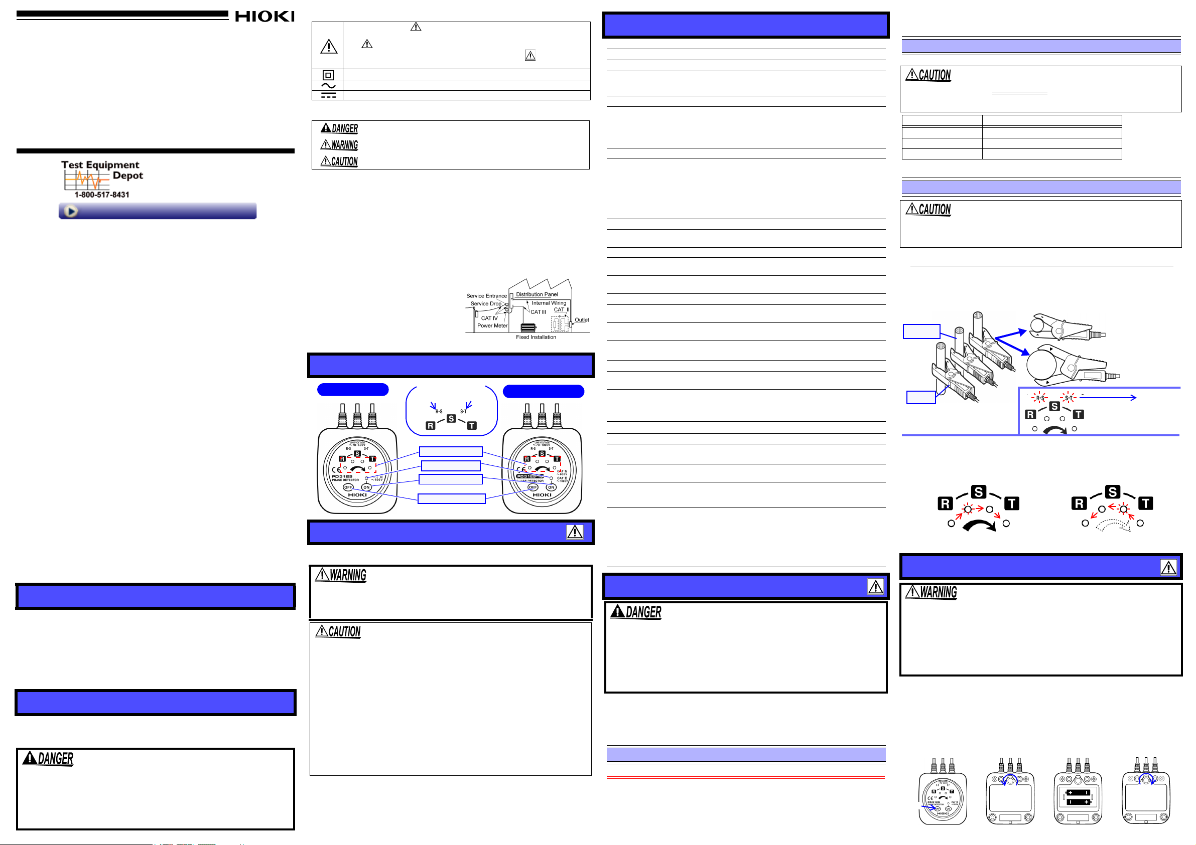
PD3129,PD3129-10
Model PD3129-10
R-S Lamp S-T Lamp
Model PD3129
Line-voltage Lamp
Power ON Switch
Power OFF Switch
Power ON Lamp
Phase-sequence
Attach the voltage clips to the
insulated wires of a 3-phase
AC circuit.
Light up
If the wires are live, the
line-voltage lamps R-S
and S-T will light up.
3. If the phase-sequence lamps blink in the order of the direction indicated by
the arrow (clockwise), the connected circuit has a positive phase sequence
(R-S-T). The buzzer will sound intermittently.
1.
Buzzer (Intermittent sound) Buzzer (Continuous sound)
2.
Insulated
wire
Barrier
(Place the wire at
the
mark on
the clip.)
Blinks in order (Clockwise).
Blinks in order (Counterclockwise).
<Negative phase sequence (T-S-R)>
<
Positive phase sequence (R-S-T)>
The arrow lamp lights up.
The arrow lamp turns off.
1. Turn OFF the power.
2.
Turn over the phase detector. Remove the screw, then remove the battery cover.
3. Replace the batteries with new ones, noting the polarity.
4. Put the battery cover back in place, and tighten the screw.
1. 2.
3.
4.
Replace
Push
Loosen
Tighten
PHASE DETECTOR
Instruction Manual
99 Washington Street
Melrose, MA 02176
Phone 781-665-1400
Toll Free 1-800-517-8431
Visit us at www.TestEquipmentDepot.com
Warranty
Warranty malfunctions occurring under conditions of normal use in conformity
with the Instruction Manual and Product Precautionary Markings will be repaired
free of charge. This warranty is valid for a period of three (3) years from the date
of purchase. Please contact the distributor from which you purchased the product for further information on warranty provisions.
Introduction
Thank you for purchasing the HIOKI Model PD3129/PD3129-10 PHASE DETECTOR. To obtain maximum performance from the instrument, please read
this manual first, and keep it handy for future reference.
Initial Inspection
When you receive the instrument, inspect it carefully to ensure that no damage
occurred during shipping. If damage is evident, or if it fails to operate according
to the specifications, contact your dealer or Hioki representative.
Maintenance and Service
• To clean the instrument, wipe it gently with a soft cloth moistened with water or
mild detergent. Never use solvents such as benzene, alcohol, acetone, ether,
ketones, thinners or gasoline, as they can deform and discolor the case.
• If the instrument seems to be malfunctioning, confirm that the batteries are
not discharged before contacting your dealer or Hioki representative.
•Pack the
include a description of existing damage. We cannot accept responsibility for
damage incurred during shipping.
• If the protective functions of the instrument are damaged, either remove it
from service or mark it clearly so that others do not use it inadvertently.
• The magnets on the rear side can be utilized to fix the instrument on a place
like a door of power distribution box.
Overview
The PD3129/PD3129-10 is a phase detector, designed to perform phase sequence
checks and live line checks of a 3-phase circuit using a static induction voltage clip.
• The static induction voltage clips are used to be able to clip on a insulated wire.
• It is small with a CAT III 600 V (Model PD3129), CAT IV 600 V, CAT III 1000
V (Model PD3129-10) safety rating.
• Red LED lamps are used to make the indication visible in dimly lit areas.
• The direction of phase sequence can be checked easily using the LED
lamps, which blink in order.
Safety
This manual contains information and warnings essential for safe operation of
the instrument and for maintaining it in safe operating condition. Before using it,
be sure to carefully read the following safety precautions.
This instrument is designed to comply with IEC 61010 Safety
Standards, and has been thoroughly tested for safety prior to
shipment. However, mishandling during use could result in
injury or death, as well as damage to the instrument. Be certain
that you understand the instructions and precautions in the
manual before use. We disclaim any responsibility for accidents or injuries not resulting directly from instrument defects.
instrument so that it will not sustain damage during shipping, and
In the manual, the symbol indicates particularly important information
that the user should read before using the instrument.
The symbol printed on the instrument indicates that the user should refer
to a corresponding topic in the manual (marked with the symbol) before
using the relevant function.
Indicates a double-insulated device.
Indicates AC (Alternating Current).
Indicates DC (Direct Current).
The following symbols in this manual indicate the relative importance of cautions and warnings.
Measurement categories
This instrument complies with CAT III 600 V (Model PD3129), CAT III 1000 V, CAT IV 600
V (Model PD3129-10) safety requirements. To ensure safe operation of measurement
instruments, IEC 61010 establishes safety standards for various electrical environments,
categorized as CAT II to CAT IV, and called measurement categories.
CAT II : Primary electrical circuits in equipment connected to an AC electrical outlet by a
CAT III : Primary electrical circuits of heavy equipment (fixed installations) connected
CAT IV: The circuit from the service drop to the service entrance, and to the power meter
Using a measurement instrument in an environment designated with a higher-numbered category than that for which the instrument is rated
could result in a severe accident, and must be
carefully avoided.
Use of a measurement instrument that is not CATrated in CAT II to CAT IV measurement applications could result in a severe accident, and must
be carefully avoided.
Indicates that incorrect operation presents an extreme hazard that could
result in serious injury or death to the user.
Indicates that incorrect operation presents a significant hazard that could
result in serious injury or death to the user.
Indicates that incorrect operation presents a possibility of injury to the
user or damage to the device.
power cord (portable tools, household appliances, etc.)
CAT II covers directly measuring electrical outlet receptacles.
directly to the distribution panel, and feeders from the distribution panel to outlets.
and primary overcurrent protection device (distribution panel).
Names of Parts
Usage Notes
Follow these precautions to ensure safe operation and to obtain the full benefits
of the various functions.
• Do not allow the instrument to get wet, and do not use it with wet
Specifications
Basic Specifications
Function Phase detection (positive/negative)
Voltage detection method Static induction
Performance-guarantee
voltage range
Operating frequency range 45 to 66 Hz
Object to be connected
3-phase
Model PD3129:70 to 600 VAC (sine wave, continuous)
Model PD3129-10:70 to 1000 VAC (sine wave, continuous)
Insulated wire
Model PD3129 (nominal sectional area of the conductor:
2 to 100 mm
Model PD3129 -10 (nominal sectional area of the conductor:
14 to 500 mm
2
, finished outer diameter: up to φ2 to 17 mm)
2
, finished outer diameter: up to φ7 to 40 mm)
Display
Positive phase sequence:
The arrow lamp lights up, the four phase-sequence lamps
blink in order (clockwise), and the buzzer sounds intermit-
Phase-detection indication
Line-voltage indication R-S lamp, S-T lamp
Power indication
tently.
Negative phase sequence:
The arrow lamp turns off, th
blink in order (counterclockwise), and the buzzer sounds
continuously.
Power ON lamp: lights up (Power ON)
blinks (Battery Low)
e four phase-sequence lamps
General Specifications
Operating temperature
and humidity
Storage temperature
and humidity
Location for use Altitude up to 2000 m (6562 feet), indoors
Maximum rated voltage
to earth
Dielectric strength
Power supply
Maximum rated powers 300 mVA
Continuous operating time*
Auto Power Off
(This function can not
be canceled.)
Auxiliary function
Cable length Approx. 0.7 m (27.56”)
Dimensions
Mass
Options
Applicable standards
0 to 40°C (32 to 104°F), 80% RH or less
(with no condensation)
-20 to 60°C (-4 to 140°F), 80% RH or less
(with no condensation)
Model PD3129: 600 V (CAT III)
Model PD3129-10: 1000 V (CAT III)
Model PD3129: 7060 Vrms
Model PD3129-10: 8540 Vrms
Rated supply voltage 1.5 VDC
R6P Manganese battery (AA size)
Approx. 70 hours (Power ON, Standby state, using R6P
manganese battery) *Battery life
The power will be turned off automatically if the instrument
remains idle for 15 minutes after the power is turned on.
To reset, turn the power on again using the Power ON
switch.
Magnet
× 4 pcs (on rear side)
Approx. 70W
(2.76"W
Model PD3129: Approx. 200 g (7.1 oz.)
Model PD3129-10: Approx. 240 g (8.5 oz.)
Carrying case, Strap*, Spiral tube*, Instruction manual,
Two R6P Manganese batteries (AA size)
*Attaching as the occasion demands.
Safety
Model PD3129: EN61010 Pollution degree 2,
Measurement category CAT III (600 V)
(anticipated transient overvoltage 6000 V)
Model PD3129-10: EN61010 Pollution degree 2,
Measurement category
CAT IV(600 V), CAT III (1000 V)
(anticipated transient overvoltage 8000 V)
EN61326
EMC
× 75H × 30D mm
× 2.95"H × 1.18"D) (excluding projections)
× 2
Measurement Procedures
hands. This may cause an electric shock.
• Do not fix the magnets of the rear side of the instrument on bare
conductor or busbar. It may cause short circuits.
Observe the following precautions to avoid electric shock.
• Do not put magnet cards near the instrument. It may damage the
stored data.
• The instrument should not be used by anyone with a pacemaker or
any other medical devices installed in his/her body.
• This instrument is designed for use indoors. It can be operated at temperatures between 0 and 40°C without degrading safety.
• To avoid damage to the instrument, protect it from physical shock
when transporting and handling. Be especially careful to avoid physical shock from dropping.
• Do not use the instrument near a source of strong electromagnetic radiation, or near a highly electrically charged object. These may cause
a malfunction.
• To avoid breaking the cables, do not bend or pull them.
• Avoid stepping on or pinching cables, which could damage the cable
insulation.
• Keep in mind that, in some cases, conductors and wires to be measured may be hot.
To avoid corrosion from battery leakage, remove the batteries from the instrument if it is to be stored for a long time.
• Do not hold the tip of a voltage clip ahead of its barrier.
• The maximum rated voltage between input terminals and ground is
600V AC (Model PD3129:CAT III), 1000V AC (Model PD3129-10:CAT III).
Attempting to measure voltages exceeding these limits with respect
to ground could damage the instrument and result in personal injury.
• Even if the line-voltage lamps do not light up, the line may be live. (ex.
When the earth potential is 70 VAC or less.) Do not touch the line.
Preliminary Checks
• Before using the instrument the first time, make sure that the no damage occurred during storage or shipping, that the insulation on the cables is undamaged, and that no
bare conductors are improperly exposed. Using the instrument in such conditions could
cause an electric shock, so contact your dealer or Hioki representative for repair.
• When the Power ON lamp is blinking, the batteries are running low. Replace the batteries.
Step 1. Performance Check (Indispensable)
Be sure to check the following before use to avoid electrical shock.
Connect each voltage clips to single wire (live line) 70 VAC or more, and check
to see if the line-voltage lamp light up. Do not use shielding wire.
Lamp lights up : It can be used.
Lamp does not light up : Do not use it and contact your dealer or Hioki repre-
sentative for repair.
Test Equipment Depot - 800.517.8431 - 99 Washington Street Melrose, MA 02176 - TestEquipmentDepot.com
× 2
Wire diameter limits Model PD3129:φ
Be sure to use the correct phase detector according to your wire size.
2 to 17 mm,
Model
PD3129-10:φ7 to 40 mm
Step 2. Live Line Check
A live line check can be conducted using one of the voltage clips.
• Be sure to clip on a insulated wire.
• If the tip of the clip is closed, a live line check cannot be conducted.
• Do not use shielding wire.
Voltage clip used Line-voltage lamp to light up
R (red) R-S lamp only
S (white) R-S lamp and S-T lamp
T (blue) S-T lamp only
Lamp lights up
Lamp does not light up
: The line is live.
: The line is not live or the earth potential is 70 VAC or less.
Step 3. Detection
Since the voltage sensors are based on the static induction, it is impossible to find the missing phase of the grounding line on 3-phase 3-lead
circuits in principle. In this case, the positive or negative phase
sequence may be indicated.
• Do not touch the clips during detection. It may cause a malfunction.
• Always connect three voltage clips to the insulated wires before detecting.
can not be detected properly, if two or less clips are connected. The phase
detector (Models PD3129 and PD3129-10) will operate on 2 wires, but this is
not proper phase detection.
• Do not detect any circuit except a 3-phase AC circuit. It causes a malfunction.
Replacing Battery
• To avoid electric shock when replacing the batteries, first disconnect the voltage clips from the object to be measured, and turn off
the power.
• After replacing the batteries, replace the battery cover and screws
before using the instrument.
• Battery may explode if mistreated. Do not short-circuit, recharge,
disassemble or dispose of in fire.
• Handle and dispose of batteries in accordance with local regulations.
Low-battery indicator: When the Power ON lamp is blinking, the batteries are
Tools
Screwdriver, Two new R6P manganese batteries (LR6 alkaline battery can be used also.)
running low. Replace the batteries.
It
 Loading...