

Page 1

Contens
Test Equipment Depot - 800.517.8431 - 99 Washington Street
Melrose, MA 02176 TestEquipmentDepot.com
Introduction .......................................................................... 1
Verifying Package Contents ................................................2
Safety Information ................................................................ 3
Operating Precautions .........................................................7
Chapter 1 Overview 11
1.1 Product Overview ..............................................11
1.2 Features ............................................................ 14
1.3 Names and Functions of Parts ..........................16
Operation key ....................................................18
Display Indicators ..............................................19
Chapter 2 Measurement 21
2.1 Measurement process ....................................... 21
2.2 Preparing for Measurement ..............................22
Attaching the Strap............................................. 22
Installing (or Replacing) the Battery ..................23
2.3 Pre-Operation Inspection .................................. 25
Using the included resistance check loop to
inspect the instrument .......................................26
2.4 Measurement Procedure ................................... 27
Resistance Measurement .................................28
Current Measurement ....................................... 31
2.5 Convenient function ..........................................35
Data hold function (Holding the measured value) 35
Backlight function
(Making measurements in a dark location) ....... 35
Filter function (Rejecting noise) ......................... 36
Alarm function (Judging measured values and
sounding an alarm) ...........................................37
Memory function (Saving measurement data) .. 40
Page 2

ii
Making measurements with an Android™ handset
(FT6381 only) ....................................................44
Enabling the Bluetooth
Pairing the instrument with an Android™ handset
(first use only).................................................... 46
Installing the FT6381 Communication Software
on the Android™ handset ..................................47
Registering the instrument you wish to connect
with the FT6381 Communication Software ........48
Switching the FT6381 to connect with the
Android™ handset .............................................50
Using the FT6381 Communication Software
(second and subsequent use) ...........................50
2.6 Advanced Settings and Functions .....................53
Enabling/disabling the measurement range
display function ..................................................54
Enabling/disabling the auto-power-saving (APS)
function .............................................................. 55
Reverting the instrument to factory settings
(system reset).....................................................56
Chapter 3 Specifications 57
3.1 Measurement Specifications .............................57
3.2 General Specifications .......................................61
Chapter 4 Maintenance and Service 65
®
function on the FT6381 45
4.1 Cleaning ............................................................65
4.2 Troubleshooting ................................................. 66
Inspection and Repair ........................................66
Before returning for repair .................................66
4.3 Error Display ......................................................67
Page 3

Introduction
Introduction
Thank you for purchasing the HIOKI Model FT6380, FT6381
CLAMP ON EARTH TESTER. To obtain maximum performance
from the instrument, please read this manual first, and keep it
handy for future reference.
Registered Trademarks
• Bluetooth
(USA).
• Android
tooth
• Adobe and Reader are either registered trademarks or trademarks of Adobe Systems Incorporated in the United States and
/or other countries.
®
is a registered trademark of Bluetooth SIG, Inc.
TM
Google PlayTM is a registered trademark of Blue-
®
Google, Inc.
1
Page 4

Verifying Package Contents
When you receive the instrument, inspect it carefully to
ensure that no damage occurred during shipping. In particular, check the accessories, panel switches, and connectors. If
damage is evident, or if it fails to operate according to the
specifications, contact your dealer or Hioki representative.
Confirm that these contents are provided.
□
FT6380 or FT6381 Clamp On Earth Tester (1)
□ Instruction Manual (1)
□ Carrying Case (1)
□ Resistance Check Loop (1)
□ LR6 alkaline batteries (2)
□ Strap (1)
2
Verifying Package Contents
Package Contents
Use the original packing materials when transporting the instrument, if
possible.
For other transportation notes, refer to the "Transporting (p.66)".
Page 5

Safety Information
Safety Information
This instrument is designed to comply with IEC 61010
Safety Standards, and has been thoroughly tested for
safety prior to shipment. However, mishandling during use
could result in injury or death, as well as damage to the
instrument. However, using the instrument in a way not
described in this manual may negate the provide d safety
features. Be certain that you understand the instructions
and precautions in the manual before use. We disclaim any
responsibility for accidents or injuries not resulting directly
from instrument defects.
This manual contains information and warnings essential for
safe operation of the instrument and for maintaining it in safe
operating condition. Before using it, be sure to carefully read the
following safety precautions.
Safety Symbols
In the manual, the symbol indicates particularly
important information that the user should read
before using the instrument.
The symbol printed on the instrument indicates
that the user should refer to a corresponding topic in
the manual (marked with the symbol) before
using the relevant function.
Indicates a double-insulated device.
Indicates AC (Alternating Current).
Indicates that the instrument may be connected to or
disconnected from a live circuit.
Indicates the power on/off button.
3
Page 6

Safety Information
4
The following symbols in this manual indicate the relative importance of cautions and warnings.
Indicates that incorrect operation presents an
extreme hazard that could result in serious
injury or death to the user.
Indicates that incorrect operation presents a
significant hazard that could result in serious
injury or death to the user.
Indicates that incorrect operation presents a
possibility of injury to the user or damage to the
instrument.
Indicates advisory items related to performance or correct operation of the instrument.
Symbols for Various Standards
WEEE marking:
This symbol indicates that the electrical and
electronic appliance is put on the EU market
after August 13, 2005, and producers of the
Member States are required to display it on the
appliance under Article 11.2 of Directive 2002/
96/EC (WEEE).
This symbol indicates that the product conforms
to safety regulations set out by the EC Directive.
®
FCC ID
Indicates that the product incorporates Bluetooth
wireless technology. Bluetooth® is a registered
trademark of Bluetooth SIG, Inc., and is used
under license by HIOKI E.E. CORPORATION.
Indicates that the product conforms to the
domestic Japanese technical standards set forth
by the Radio Act (type certification).
Indicates the ID number of the wireless module
certified by the U.S. Federal Communications
Commission (FCC).
Page 7

IC
Over-range display
Open display
Resistance measurement: When the reading exceeds 1,600 Ω
Current measurement: When the reading
exceeds 60.0 A.
This screen is displayed when the clamp
sensor is not completely closed during use
of the resistance measurement function.
Indicates the number of the wireless module
certified by Industry Canada.
Other Symbols
Indicates a prohibited action.
Safety Information
5
(p. #)
[ ] Information displayed on the screen is enclosed
Fn
(bold
characters)
The screen of this instrument displays characters in the following manner.
Screen displays that differ from the above notation:
Indicates the location of reference information.
in brackets.
Bold text indicates alphanumeric characters
shown on operation keys.
Page 8
Safety Information
6
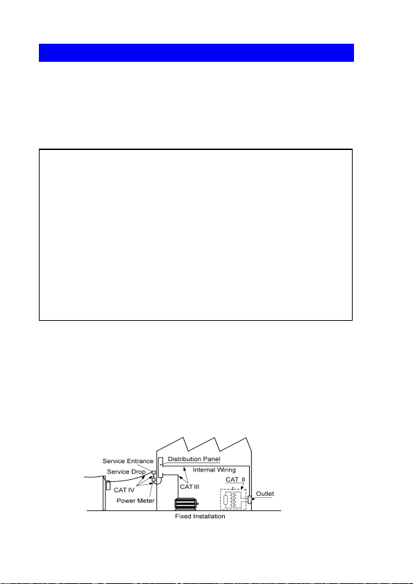
Measurement categories
This instrument complies with CAT IV safety requirements.
To ensure safe operation of measurement instruments IEC
61010 establishes safety standards for various electrical environments, categorized as CAT II to CAT IV, and called measurement categories.
Primary electrical circuits in equipment connected
CAT II
CAT III
CAT IV
Using a measurement instrument in an environment designated
with a higher-numbered category than that for which the instrument is rated could result in a severe accident, and must be
carefully avoided.
Use of a measurement instrument that is not CAT-rated in CAT II
to CAT IV measurement applications could result in a severe
accident, and must be carefully avoided.
to an AC electrical outlet by a power cord (portable
tools, household appliances, etc.)
CAT II covers directly measuring electrical outlet
receptacles.
Primary electrical circuits of heavy equipment
(fixed installations) connected directly to the distribution panel, and feeders from the distribution
panel to outlets.
The circuit from the service drop to the service
entrance, and to the power meter and primary
overcurrent protection device (distribution panel).
Page 9

Operating Precautions
Operating Precautions
Follow these precautions to ensure safe operation and to obtain
the full benefits of the various functions.
Preliminary Checks
Before using the instrument for the first time, verify that it operates normally to ensure that no damage occurred during storage
or shipping. If you find any damage, contact your dealer or Hioki
representative.
Instrument Installation
Operating temperature:-10 to 50°C (14 to 122°F)
(Be sure to use batteries that are suited for use under the environmental conditions in which you are using the instrument.)
Operating humidity: 80%RH or less (non condensating),
Avoid the following locations that could cause an accident or
damage to the instrument.
Exposed to direct
sunlight
Exposed to high temperature
Exposed to water, oil,
other chemicals, or
solvents Exposed to
high humidity or condensation
Exposed to high levels of particulate dust
In the presence of corrosive or explosive
gases
Exposed to strong
electromagnetic fields
Near electromagnetic
radiators
Near electromagnetic
radiators (e.g., highfrequency induction
heating systems and
IH cooking utensils)
7
Subject to vibration
Page 10
Operating Precautions
8
Handling the Instrument
• To avoid short circuits and potentially life-threatening
hazards, never attach the clamp to a circuit that operates
at more than 600 V, or over bare conductors.
• The maximum rated voltage between input terminals and
ground is 600 VAC. Measuring a voltage in excess of this
rating relative to ground could damage the instrument
and result in bodily injury.
• To avoid electric shock, do not remove the instrument's
case. The internal components of the instrument carry
high voltages and may become very hot during operation.
• When the clamp sensor is opened, do not allow the metal
part of the clamp to touch any exposed metal, or to short
between two lines, and do not use over bare conductors.
To avoid electric shock when measuring live lines, wear
appropriate protective gear, such as insulated rubber
gloves, boots and a safety helmet.
Page 11

Operating Precautions
Frequency [Hz]
Current [A]
• Do not input a current in excess of the maximum allowable
current. Doing so may damage the instrument or cause burns.
The maximum allowable current is 100 AAC continuous or
200 A AC within two minutes at 50/60 Hz. For more information about the frequency derating characteristics during continuous input, see the following diagram:
• To avoid damage to the instrument, protect it from physical
shock when transporting and handling. Be especially careful
to avoid physical shock from dropping.
• Be careful to avoid dropping the instrument or otherwise subjecting them to mechanical shock, which could damage the
mating surfaces of the core and adversely affect measurement.
• Although this instrument is dust resistant, it is not completely
dust- or waterproof. To prevent possible damage, avoid using
in dusty or wet environments.
• Do not slant the device or place it on top of an uneven surface.
Dropping or knocking down the device can cause injury or
damage to the device.
9
Page 12

Operating Precautions
10
• The protection rating for the enclosure of this device (based
on EN60529) is *IP40. (The rating applies to the clamp sensor
when in the closed position.)
*IP40
This indicates the degree of protection provided by the enclosure of the device against use in hazardous locations, entry of
solid foreign objects, and the ingress of water.
4: Protected against access to hazardous parts with wire mea-
suring 1.0 mm in diameter. The equipment inside the enclosure is protected against entry by solid foreign objects larger
than 1.0 mm in diameter.
0: The equipment inside the enclosure is not protected against
the harmful effects of water.
Page 13

1.1 Product Overview
11
Overview Chapter 1
1.1 Product Overview
The FT6380 and FT6381 Clamp On Earth Tester make grounding resistance measurements simply by being clamped to multiple-grounded ground wires. No auxiliary grounding rod is
needed, and there is no need to disconnect the ground wire from
the grounding rod.
The instruments also provide AC current measurement functionality and can measure currents ranging from leakage current on
the order of several mA to load currents of up to 60 A.
The FT6381 can only be used in Japan, the U.S., Canada, and
the EU. Because it incorporates Bluetooth
the instrument emits radio radiation. Use of devices that emit
radio radiation requires approval in the country of use, and use
of the instrument in a country or region other than those listed
above may be subject to penalty as a violation of law.
This device complies with part 15 of the FCC Rules. Operation is
subject to the following two conditions: (1) This device may not
cause harmful interference, and (2) this device must accept any
interference received, including interference that may cause
undesired operation.
FCC CAUTION
Changes or modifications not expressly approved by the party
responsible for compliance could void the user's authority to
operate the equipment.
Note: This equipment has been tested and found to comply with
the limits for a Class B digital device, pursuant to part 15 of the
®
wireless technology,
Page 14

1.1 Product Overview
12
FCC Rules. These limits are designed to provide reasonable
protection against harmful interference in a residential installation. This equipment generates, uses and can radiate radio frequency energy and, if not installed and used in accordance with
the instructions, may cause harmful interference to radio communications. However, there is no guarantee that interference
will not occur in a particular installation. If this equipment does
cause harmful interference to radio or television reception, which
can be determined by turning the equipment off and on, the user
is encouraged to try to correct the interference by one or more of
the following measures:
-Reorient or relocate the receiving antenna.
-Increase the separation between the equipment and receiver.
-Connect the equipment into an outlet on a circuit different from
that to which the receiver is connected.
-Consult the dealer or an experienced radio/TV technician for
help.
This transmitter must not be co-located or operated in conjunction with any other antenna or transmitter.
This equipment complies with FCC radiation exposure limits set
forth for an uncontrolled environment and meets the FCC radio
frequency (RF) Exposure Guidelines in Supplement C to
OET65. This equipment has very low levels of RF energy that it
deemed to comply without maximum permissive exposure evaluation (MPE). But it is desirable that it should be installed and
operated keeping the radiator at least 20cm or more away from
person's body (excluding extremities: hands, wrists, feet and
ankles).
This Class B digital apparatus complies with Canadian ICES-
003.
Page 15

1.1 Product Overview
This device complies with Industry Canada licence-exempt RSS
standard(s). Operation is subject to the following two conditions:
(1) this device may not cause interference, and (2) this device
must accept any interference, including interference that may
cause undesired operation of the device.
This equipment complies with IC radiation exposure limits set
forth for an uncontrolled environment and meets RSS-102 of the
IC radio frequency (RF) Exposure rules. This equipment has
very low levels of RF energy that it deemed to comply without
maximum permissive exposure evaluation (MPE). But it is desirable that it should be installed and operated keeping the radiator
at least 20cm or more away from person's body (excluding
extremities: hands, wrists, feet and ankles).
13
Page 16

1.2 Features
14
1.2 Features
Compact, low-profile sensor
The compact, low-profile sensor can be used to clamp ground wires
with ease. The sensor design dramatically speeds the measurement
process by eliminating the need to pull out g round wires for clamping
or dig around the ground rod or wire.
Broad dynamic range
The instrument can easily measure grounding resistance of up to
0.02 to 1,600 Ω with its auto-range function. Current measurement
ranges from small leakage current (maximum resolution 10 A) to a
maximum of 60 A.
Noise check function (p.30)
The instrument automatically detects noise that may affect grounding resistance measurement and displays a mark.
True RMS display
True RMS calculation allows the instrument to accurately measure
distortion waveform currents.
Data hold function (p.35)
A large button that is easy to push lets you hold the measured value.
The button notifies the user of the hold status by flashing while the
value is being held.
Backlight function (p.35)
The instrument uses a white LED for excellent visibility so that display values can be read clearly, even in dark locations.
Auto-power-save (APS) function (p.55)
An auto-power-save function keeps batteries from running down
when you forget to turn off the instrument.
Page 17

1.2 Features
15
Alarm function (p.37)
By setting a threshold, you can have the instrument make a PASS/
FAIL judgment and notify you of the result with a buzzer. You can set
separate thresholds for resistance and current measurements and
select judgment criteria (whether to generate a FAIL result when t he
reading is greater than or less than the threshold).
Filter function (p.36)
Widespread use of switching power supplies and inverters has led to
cases where harmonic components are superimposed on leakage
current waveforms. The instrument’s filter function allows it to perform two types of measurement: leakage current as related to degradation of insulation, and leakage current including this harmonic
component.
Internal memory (p.40)
The instrument’s internal memory can record up to 2,000 measured
values.
Automatic measurement report function with
Android
™ connectivity (*FT6381 only) (p.44)
The FT6381 features Bluetooth® wireless technology and can be
connected to a smartphone running the Android o perating system to
easily create measurement reports in the field. (FT6381 availability
is limited to certain countries. For more information, contact your
dealer or Hioki representative.)
Page 18

1.3 Names and Functions of Parts
Barrier
Front
Clamp sensor
FT6380 FT6381
POWER key
HOLD key
(p.35)
A/Ω key
Backlight key
(p.35)
Display Indicator
(p.19)
Operation key
(p.18)
16
1.3 Names and Functions of Parts
POWER key
HOLD key
Backlight key
A/Ω key
• Used to turn the instrument on and off.
• To temporarily cancel the auto-power-save function,
press the POWER key while holding down the HOLD
key.
• Holds the measured value display or cancels hold
mode.
• To cancel auto-power-save mode, press the POWER
• Turns the backlight on and off.
• Switches between resistance measurement mode and
key while holding down the HOLD key.
current measurement mode.
Page 19

Battery cover
(p.23)
Back
Strap hole
(p.22)
Bottom
FT6380
FT6381
Serial No.
1.3 Names and Functions of Parts
17
Page 20

1.3 Names and Functions of Parts
Operation key
18
Key Description
Switches to function mode, which is used to configure settings. Pressing this key again will return to resistance measurement mode or current measurement mode.
• Enables the alarm function. (p.37)
• When the alarm function is enabled, the instrument will
notify the user with the buzzer if a reading is greater than (or
less than) a preset threshold.
• Alarm function threshold settings can be configured in function mode. (p.39)
*In function mode, this key serves as the
used to select setting items and values.
• Pressing this key while using the current measurement function enables the low-pass filter to reject unneeded harmonic
components. (p.36)
• Pressing it while using the resistance measurement function
enables the moving average function, allowing more stable
measurement. (p.36)
*In function mode, this key serves as the
used to select setting items and values.
Saves measurement data to the instrument’s internal memory. (p.40)
*In function mode, this key serves as the
used to accept setting items and values.
▼ key, which is
▲ key, which is
OK key, which is
Page 21

Display Indicators
1.3 Names and Functions of Parts
Lights up when data is being held. (p.35)
Lights up in function mode. (p.52)
Flashes in subfunction mode. (p.53)
Lights up when the alarm function is on. (p.37)
Lights up when the filter function is on. (p.36)
Lights up when the Bluetooth
data is being sent or received. (model FT6381 only) (p.44)
Lights up when the auto-power-save function is on. (p.55)
Indicates the remaining battery power. (p.24)
Lights up in AC current measurement mode. (p.31)
Lights up in resistance measurement mode. (p.28)
Lights up in resistance measurement mode when a current
that could affect the measured value is detected. (p.30)
Lights up in resistance measurement mode when the mea-
sured ground loop has a high reactance component or capacitance component (
lights up due to a low measured resistance value, it is likely
that the displayed value indicates a shorted measurement
loop rather than normal grounding resistance. When the
] mark lights up, the loop may have a break in it. In this
[
case, the mark indicates that the wires have been coupled by
capacitance.) (p.30)
Lights up during internal memory operations. (p.40)
The number of measurement data points stored in memory is
shown to the right.
±45° or greater). (When the [ ] mark
®
function is on. Flashes when
19
Page 22

1.3 Names and Functions of Parts
20
Lights up when the range display function is on.
The measurement range is shown to the right.
Page 23

Measurement Chapter 2
Measurement
Resistance Measurement (p.28)
Current Measurement (p.31)
End of measurement
Remove the instrument from the measurement target.
Turn off the instrument.
Measurement Preparations
Pre-Operation Inspection (p.25)
Using the included resistance check loop to inspect the
instrument (p.26)
3
2
1
2.1 Measurement process
2.1 Measurement process
21
Page 24

2.2 Preparing for Measurement
22
2.2 Preparing for Measurement
After purchasing the instrument
Complete the following steps before using the instrument to
make measurements.
Attaching the Strap
Attach both ends of the Strap securely to the instrument.
If insecurely attached, the instrument may fall and be damaged
when carrying
Thread the strap through the strap hole as shown in the following diagram:
Page 25

2.2 Preparing for Measurement
23
Installing (or Replacing) the Battery
Before using the instrument for the first time, install two AA-size
alkaline batteries (LR6). Verify that there is sufficient battery
power remaining before measurement. If there is insufficient battery power remaining, replace the batteries.
• To avoid electric shock when replacing the batteries, first
disconnect the clamp from the object to be measured.
• After replacing the batteries, replace the cover and
screws before using the instrument.
• Battery may explode if mistreated. Do no t short- circuit,
recharge, disassemble o r dispose of in fire.
• Handle and dispose of batteries in accordance with local
regulations
• Do not mix old and new batteries, or different types of batteries. Also, be careful to observe battery polarity during installation. Otherwise, poor performance or damage from battery
leakage could result.
• To avoid corrosion from battery leakage, remove the batteries
from the instrument if it is to be stored for a long time.
•
The indicator lights when battery voltage becomes
low. Replace the batteries as soon as possible.
• Before replacing the batteries, make sure that the
Slide Switch is OFF.
• After use, always turn OFF the power.
• If the battery is completely exhausted, the display will
show [BAttLo], and the instrument will automatically
turn off.
Page 26

2.2 Preparing for Measurement
2
3
4
24
Required Items:
• Phillips screwdriver
• LR6 alkaline battery (2)
Normal procedure
Verify that the instrument is off.
1.
Remove the fastening screws of the battery cover,
2.
using a Phillips screwdriver.
Remove the battery cover.
3.
Insert two new batteries (LR06 alkaline batteries),
4.
taking care to orient them properly.
Replace the battery cover and tighten th e fastening
5.
screws.
Battery Status Indicator
This indicator is displayed at the top right corner. ?
When new alkaline batteries have been installed
When 2/3 of the battery power remains
When 1/3 of the battery power remains
No battery power remains. Replace with new batteries.
Page 27

2.3 Pre-Operation Inspection
Before using the instrument for the first time, verify that it operates normally to ensure that no damage occurred during storage or shipping. If you find any damage, contact your dealer or
Hioki representative.
Does the screen turn on when
the instrument is turned on?
The batteries may be dead.
Replace the batteries and try
again.
The instrument may be malfunctioning. Have the instrument repaired.
• Is the instrument damaged?
• Is the clamp sensor cracked
or otherwise damaged?
No
End of inspection
Yes
An error is
displayed.
• The screen is not on.
• The screen shows an
error.
Do not use the instrument if it
is damaged as doing so may
result in electric shock. Have
the instrument repaired.
Yes
1. Inspecting the instrument
2. Inspecting the instrument after turning it on
The screen is on.
Using the included resistance
check loop to inspect the instrument (p.26)
2.3 Pre-Operation Inspection
25
Page 28

2.3 Pre-Operation Inspection
Resistance check loop
26
Using the included resistance check loop to
inspect the instrument
Before turning on the instrument, be sure to read Operating Precautions (p.8).
Inspecting the instrument with the resistance check loop
Verify that there is no foreign matter lodged between the tips of
the clamp sensor and that the sensor can be closed and opened
smoothly. If so, clamp the included resistance check loop and
verify that the instrument is operating properly. Verify that a
value within the allowable range is displayed for each loop.
Test resistance Allowable range
1 Ω 0.95 to 1.05 Ω
25 Ω 24.3 to 25.7 Ω
• If the instrument displays a value outside the allowable
range, it needs to be repaired. Contact your dealer or
Hioki representative.
• The resistance check loop cannot be used to calibrate
the instrument. To have the instrument calibrated, contact your dealer.
Page 29

barrier
2.4 Measurement Procedure
2.4 Measurement Procedure
• To avoid electric shock, do not touch the portion beyond the protective barrier during use.
• When the clamp sensor is opened, do not
allow the metal part of the clamp to touch
any exposed metal, or to short between two
lines, and do not use over bare conductors.
• The maximum allowable current is 100 A AC
continuous or 200 A AC for 2 minutes (50/60 Hz). Currents
in excess of these values must be avoided as they may
damage the instrument or cause bodily injury.
• The tips of the clamp sensor are precisely manufactured in order to provide a high level of precision. Exercise caution when handling the clamp so as to avoid
subjecting it to excessive vibration, mechanical shock,
or force.
• If foreign matter gets stuck between the tips of the
clamp sensor, do not forcibly open or close the sensor,
but rather use a soft brush or similar implement to
carefully remove the foreign matter. Accurate measurements cannot be made while foreign matter is
stuck between the tips of the clamp sensor or while the
shape of the clamp sensor is deformed. If the tips of
the clamp sensor become deformed, have the instrument inspected and calibrated by your dealer.
27
Page 30

2.4 Measurement Procedure
RmR
x
1
1
R
i
-----
i 1=
n
------------------+=
R
x
1
1
R
i
-----
i 1=
n
------------------»
R
x
R
1
R
n
R
2
28
Resistance Measurement
Measuring Principle
As illustrated below, the instrument is designed to measure
grounding resistance at multiple grounding locations. (*For applications involving the measurement of grounding resistance at a
single grounding site, use Hioki’s 3151 EARTH HiTESTER.)
If the grounding resistance of the measurement target is represented by R
grounded locations are represented by R
tance value measured by the product is as follows:
If n is sufficiently large and each Ri value is sufficiently small,
and the grounding resistance values of other
x
, R2, …, Rn, the resis-
1
and the second term can be ignored, allowing the value of
R
to be measured.
x
Page 31

2.4 Measurement Procedure
R
x
R
1
R
n
R
x
29
Example with actual measured values
The following provides an example with actual measured values.
The more grounding electrodes there are in the multiplegrounded installation, the higher the accuracy of the obtained
values. Alternately, if even one grounding electrode has a small
value (for example, 1 Ω), accurate values can be approached
even if there are few grounding electrodes. Since most multiplegrounded systems have a large number of grounding electrodes, the error can be limited.
Measuring method
Select resistance measurement mode.
1.
Select resistance measurement mode with the A/Ω key.
Clamp the grounding wire you wish to measure.
2.
The resistance value will be displayed.
Page 32

2.4 Measurement Procedure
30
• Verify that the mark is not lit up.
When the current flowing through the grounding wire is high
(approximately 2.5 A or greater with a commercial frequency
of 50/60 Hz), the current will affect measured values, making
it impossibl e to measure the r esistance. Check t he current
flowing through the grounding wire.
• Open display
The screen will show [OPEn] if the clamp is not completely closed. Close the clamp completely and repeat
the measurement.
*If an extremely large current is flowing through the
grounding wire, the screen may display [OPEn] even
if the clamp is completely closed. This does not signal
a malfunction. Check the current flowing through the
grounding wire by using the instrument’s current measurement mode.
• Inductor and capacitor marks
If the [ ] marks next to the resistance mark light up
during measurement, the grounding resistance includes
an in-series L or C component. If the [
with an extremely small mea sured value such as 0.1 Ω,
the instrument may be un able to measure t he grounding
resistance because the grounding wire itself has formed a
loop. If the [
the loop. (In this case, the wires are being coupled by
capacitance.) In either of th es e cases , i t is reco mme nded
to verify that the re is neith er a s hort n or a wi ring b reak in
the location being measured.
• Do not measure the same location with two or more
Clamp On Earth Testers at the same time. The instruments will interfere with each other, preventing accurate measurement.
]
mark lights up, there may be a break in
]
mark is shown
Page 33

2.4 Measurement Procedure
Current Measurement
Select current measurement mode with the A/Ω key.
1.
Position the conductor in the center of the clamp
2.
sensor.
The current RMS value will be shown on the display.
3.
31
Page 34

2.4 Measurement Procedure
OK NG
32
• The frequency of special waveforms such as at the
secondary side of an inverter may not be indicated correctly.
• Depending on the magnitude and frequency of the
input current, resonances may be heard from the
clamp jaw. This does not affect the measurement.
• Do not input a current in excess of the maximum allowable current for the current range being used.
Page 35

Measuring zero-phase current
Single-phase, 2-lead circuits
three-phase 3-lead circuits
clamp all three leads of the
circuit
Load
device
Load
device
lg
When measuring zero-phase current, clamp all of the circuits at
once.
2.4 Measurement Procedure
33
Page 36

2.4 Measurement Procedure
34
Do not input current that exceeds the maximum continuous input of the electric current range.
• Measurement may not be accurate in the cases below.
(1) When there is large current (of about 100 A) flow-
ing through a nearby electric line
(2) Note that a value of several tens of amperes may
be displayed when opening or closing the clamp
sensor, or when changing the electric current
range. This is not an error. It may take some time
for the display to return to zero. However, starting
measurement before the display returns to zero will
not affect measurement.
• Enable the "Filter function (Rejecting noise) (p.36)"
when conducting measurement in the cases below.
(1) When meaningless data is displayed due to noise.
(2) When using the instrument to measure special
waveforms, such as those on the secondary side of
an inverter
The instrument may not be able to perform measure-
ment in the cases below.
(1) When using input current that is 1/10 or less of the
full electric current range
(2) When measuring high frequencies with the filter
function enabled.
Page 37

2.5 Convenient function
35
2.5 Convenient function
Data hold function (Holding the measured value)
This function holds the measured value and continues to display
that value.
Press the HOLD key. The instrument will beep twice and the
[ ] mark will be displayed, and the measured value will be
held. The HOLD key will flash. To cancel hold mode, press the
HOLD key again. The instrument will beep once and the [ ]
mark will disappear, and the HOLD key will stop flashing.
Backlight function
(Making measurements in a dark location)
This function makes the display easier to see in dark locations.
Press the BACKLIGHT key ( ). The backlight will turn on.
The backlight will turn off automatically when there has been no
operation for about 2 minutes.
To turn off the backlight, press the BACKLIGHT key ( ) again.
The backlight will turn off.
Page 38

2.5 Convenient function
36
Filter function (Rejecting noise)
This function allows you to reject unneeded frequency components such as high-frequency noise.
Press the FILTER key. The [ ] mark will be displayed. To
cancel the filter, press the FILTER key again. The [ ] mark
will disappear.
During resistance measurement
Using the filter function when there is a significant amount
of variation in measured values during resistance measurement will cause the measured values to stabilize.
*Note that noise rejection cannot be used when the [
mark is lit up.
During current measurement
Using the filter function enables a low-pass filter, causing
the harmonic component to be eliminated from measured
values. Widespread use of switching power supplies and
inverters has led to cases where harmonic components are
superimposed on current waveforms; the filter function is
effective in such cases. Canceling the filter function disables the low-pass filter, allowing measurement of current
including harmonic components.
]
Page 39

2.5 Convenient function
Alarm Settings screen for resistance measurement
Alarm Settings screen for current measurement
37
Alarm function
(Judging measured values and sounding an alarm)
You can sound an alarm (A high tone signifies a high alarm,
while a low tone signifies a low alarm.) using previously set
thresholds by pressing the key.
Thresholds and other settings must be configured in advance.
To cancel the alarm function, press the key again.
Configuring the alarm settings
1.
Press the Fn key to switch to function mode. Using the ▼
and ▲ keys, select the resistance or current Alarm Settings
screen and press the OK key.
*For more information about function mode, see (p.52).
Page 40

2.5 Convenient function
Lo: The alarm will sound if the measured value
is less than the set threshold value.
Hi: The alarm will sound if the measur ed value
is greater than the set threshold value.
*The Hi/Lo setting is saved once the following setting has been
configured. If you press the
Fn key after configuring the Hi/Lo set-
ting but before saving the threshold and thereby cancel the configuration process, any changes to the Hi/Lo setting will not be
saved.
38
Set the alarm type (Hi/Lo).
2.
Using the ▼ and ▲ keys, select the alarm type (Hi/Lo), and
press the OK key. The next threshold setting will start flashing.
Page 41

2.5 Convenient function
Set the threshold.
3.
After configuring the Hi/Lo setting, set the threshold.
Using the ▼ and ▲ keys, set the threshold and press the
OK key.
You can move more quickly through threshold values by
pressing and holding the ▼ and ▲ keys.
Once the settings are complete, the screen will switch to
the Alarm Settings screen. To return to resistance measurement or current measurement mode, press the Fn key
again or the A/Ω key.
39
Page 42

2.5 Convenient function
Memory number
When the number of values saved in the instrument’s memory
reaches 2,000, the display will show “FULL,” and you will not
be able to save additional values. Delete unneeded values to
free up space.
40
Memory function (Saving measurement data)
Press the MEM key in either resistance measurement mode or
current measurement mode. The instrument will beep three
times and the displayed measured value will be stored along
with the memory number (1 to 2,000) in the instrument’s internal
memory.
* Measured values, filter use, and the [ ] and [ ]
marks are saved in memory.
Page 43

2.5 Convenient function
Loading a value from the instrument’s internal memory
Press the Fn key to enter function mode.
1.
Using the ▼ and ▲ keys, select the Read Memory
screen and press the OK key.
*For more information about function mode, see (p.52).
Using the ▼ and ▲ keys, increment or decrement the
2.
memory number to recall the measured value for the
memory number you wish to load.
You can move more quickly through memory numbers
by pressing and holding the ▼ and ▲ keys.
To exit the Read Memory screen, press the Fn key or
the OK key.
* To return to resistance measurement or current mea-
surement mode, press the Fn key again or the A/Ω
key.
41
Page 44

2.5 Convenient function
To clear the last stored data point
(1 value)
(The screenshot to the left indicates
that 34 values have been saved in
the instrument’s memory.)
To clear all data points
(The screen will show [ALL].)
42
Clearing stored data
You can clear the last stored data point (1 value) or all
stored data points.
Press the Fn key to enter function mode.
1.
Using the ▼ and ▲ keys, select the Clear Memory
screen and press the OK key. The screen will show
[CLr].
*For more information about function mode, see (p.52).
Using the ▼ and ▲ keys, select either the last stored
2.
data point or all data points and press the OK key.
Page 45

2.5 Convenient function
The [OK?] mark will flash on the LCD once you select
the data to clear so that you can confirm your intentions.
Press the OK key again to clear the data.
• To cancel, press the Fn key.
• To return to resistance measurement or current measurement mode, press the Fn key again or the A/Ω
key.
43
Page 46

2.5 Convenient function
44
Making measurements with an Android™ handset
(FT6381 only)
By enabling the FT6381’s Bluetooth® function, you can transfer
measurement data to an Android™ handset to create measurement reports. For more information, refer to the help function of
the FT6381 Communication Software, an app for Android™
handsets.
In addition to installing the application, the following two sets of
connection settings must be configured in order to use the Blue-
®
tooth
function:
• Pairing the Android™ handset and FT6381
• Registering the FT6381 connection with the FT6381 Communication Software
Use the following procedure to configure the connection set tings:
Measurement process
Enable the FT6381’s Bluetooth® function.
1.
Pair the instrument with the Android™ hand-
2.
set.
Install the FT6381 Communication Software
3.
on the Android™ handset.
Register the instrument you wish to connect
4.
with the FT6381 Communication Software.
(p.45)
(p.46)
(p.47)
(p.48)
Page 47

2.5 Convenient function
Enabling the Bluetooth® function on the FT6381
Press the Fn key to enter function mode.
1.
*
For more information about function mode, see (p.52).
Using the ▼ and ▲ keys, select the Bluetooth® Setting
2.
screen and press the OK key.
45
Using the ▼ and ▲ keys, select “on” on the Bluetooth
Setting screen and press the OK key to enable the Blue-
®
tooth
function.
Use of Bluetooth® functionality shortens the battery life
compared to normal use. It is recommended to turn off
Bluetooth
®
functionality when not in use.
®
Page 48

2.5 Convenient function
0000
Pairing is only necessary the first time you use the instrument with the handset. When using multiple FT6381 instr uments, you will need to pair each instrument.
2
4
Enter
3
46
Pairing the instrument with an Android™ handset
(first use only)
Select [Wireless and Networks] from the Android™
1.
handset’s Settings button.
After enabling the Bluetooth® function, select [Scan for
2.
devices] from [Bluetooth settings] (exact words varies
with the specific Android™ handset being used; variants
include “Search for devices” and “Detect nearby terminals”).
When the handset discovers [FT6381#XXXXXXXXX] (where
3.
“XXXXXXXXX” is the serial number found on the back of the
instrument), pair the instrument.
Note that previously paired devices may appear in a separate
column labeled with language such as “Paired devices” rather
than in the search results.
Enter [0000] as the PIN number.
4.
Page 49

2.5 Convenient function
Enter and search.
Download
*The screen contents vary with the specific Android™ handset
being used. For more information about Bluetooth
®
device pair-
47
ing methods and related procedures, see your Android™ handset’s instruction manual.
Installing the FT6381 Communication Software on
the Android™ handset
Search for “FT638” on the Google Play™ store and download
and install the FT6381 Communication Software.
A Google account is required in order to download applications
from the Google Play™ store. For more information about how
to register for a Google account, contact the store from which
you purchased the Android™ handset.
Page 50

2.5 Convenient function
Select
48
The application is free, but the user is responsible for
any Internet connection costs incurred in the course of
downloading or using the application. Since such costs
may be incurred during use of the application, it is recommended to use a fixed-price plan. Hioki is not liable
for any Internet connection costs.
Registering the instrument you wish to connect
with the FT6381 Communication Software
Turn on the FT6381.
1.
Launch the FT6381 Communication Software on the
Android™ handset. If you wish to use the map function,
enable the GPS function.
From the list of Bluetooth® devices, select [FT6381#XX
2.
XXXXXXX] and press the [Settings] button. The
FT6381 will be registered.
Once the instrument has been paired, it will connect automatically, and FT6381 measured values will be sent to the Android™
handset in real time. The instrument will not be able to connect
to the handset if it has not been paired. Refer to "Pairing the
instrument with an Android™ handset (first use only) (p.46)" to
pair the instrument.
Page 51

2.5 Convenient function
49
• The screen contents vary with the specific Android™
handset being used. For more information about Blue-
®
tooth
device pairing methods and related procedures,
see your Android™ handset’s instruct io n m anual.
• Communications between the FT6381 and Android™
handset are limited to a range of about 10 m, but
obstacles (walls, metal shielding, etc.) can shorten
this distance or prevent communications from being
established.
• The FT6381’s wireless function uses Bluetooth
®
wireless technology that utilizes the 2.4 GHz band. It may
not be possible to establish communications if there is
a wireless LAN (IEEE 802.11.b/g/n) or other network/
device using the same frequency band nearby.
• The application supports Android OS 2.1 or later, but
proper operation is not guaranteed on all Android™
handsets. For more information about the devices on
which proper operation has been confirmed, see
Hioki’s website.
• Adobe’s Adobe Reader, which is available free of
charge on the Google Play™ store, is required in
order to view PDF reports. Install the application
before attempting to view reports.
• The confidentiality of information contained in Blue-
®
tooth
communications sent from the FT6381 is not
guaranteed. Hioki is not liable for any unauthorized
disclosure or other issue with measured values
caused by Bluetooth
®
communications.
• The FT6381 can only be used in Japan, the U.S., Canada, and the EU. Because it incorporates Bluetooth
wireless technology, the instrument emits radio radiation. Use of devices that emit radio radiation requires
approval in the country of use, and use of the instrument in a country or region other than those listed
above may be subject to penalty as a violation of law.
®
Page 52

2.5 Convenient function
50
Using the FT6381 Communication Software
(second and subsequent use)
After turning on the FT6381, launch the FT6381 Communication
Software on the Android™ handset. If you wish to use the map
function, enable the GPS function. Once the instrument has
been paired, it will connect automatically, and FT6381 measured
values will be sent to the Android™ handset in real time. The
instrument will not be able to connect to the handset if it has not
been paired. Refer to "Pairing the instrument with an Android™
handset (first use only) (p.46)" to pair the instrument.
Switching the FT6381 to connect with the
Android™ handset
If you have multiple FT6381 instruments and wish to change the
unit to connect to the handset, press the Settings button after
pressing the menu button on the Android™ handset and reconfigure the Bluetooth
If you are unable to establish a Bluetooth® connection
Check the following if you are unable to establish a Bluetooth
connection between the FT6381 and the Android™ handset:
• Is the Bluetooth
handset and the FT6381?
• Has the FT6381 in question been paired on the Android™
handset’s Bluetooth
not been paired, refer to "Pairing the instrument with an
Android™ handset (first use only) (p.46)" to pair it.
®
device settings.
®
function enabled on both the Android™
®
settings screen? If the instrument has
®
Page 53

2.5 Convenient function
About the FT6381 Communication Software
The application provides the following functionality:
Sending measurement data (from the LCD display) to the
Android™ handset in real time
Saving and viewing measurement data (including time
stamp, GPS position data for the measurement location,
and map data)
Creating reports from measurement data
• Single reports created from measurement data from one
location
• Summary reports that present a summary of multiple sets
of measurement data (with the ability to add comments
and change header and footer information)
Outputting measurement data as a CSV file
Sending measurement data as an e-mail
Downloading the contents of the FT6381’s internal memory
For more information about the FT6381 Communication Software application, refer to the application help.
51
Page 54

2.5 Convenient function
Current alarm settings (p.31)
Loading values from memory (p.41 )
Clearing data from the
instrument’s memory (p.42)
Resistance Alarm Settings (p.29)
2.
3.
1.
While in function mode, the [ ]
mark will light up.
1.
Press the Fn key to enter function mode.
2.
Using the ▼ and ▲ keys, select the desired setting.
3.
Accept the setting with the OK
key.
Press the Fn key or the A/Ω key
to exit function mode.
*FT6381 only
Bluetooth® Setting (p.44)
52
Function mode
In function mode, the following settings and operations are available:
• Resistance alarm settings • Current alarm settings
• Loading values from memory • Clearing data from the instrument’s
• Bluetooth
®
setting
memory
Page 55

2.6 Advanced Settings and Functions
Press the POWER key
while holding down the
Fn key.
1
2
Advanced settings can be configured in sub-function mode. In
sub-function mode, the following settings and operations are
available:
• Measurement range display setting (p.54)
• Auto-power-saving (APS) setting (p.55)
• System reset (to revert to factory settings) (p.56)
To enter sub-function mode, turn on the instrument by pressing
the POWER key while holding down the Fn key.
2.6 Advanced Settings and Functions
53
To exit sub-function mode, press the POWER key to turn off the
instrument and then turn it back on.
Page 56

2.6 Advanced Settings and Functions
54
Enabling/disabling the measurement range display
function
Enter sub-function mode.
1.
Press the POWER key while holding down the Fn key.
Using the ▼ and ▲ keys, select the Range Display Setting
2.
screen and press the OK key.
Using the ▼ and ▲ keys, switch the range display function
3.
on or off and press the OK key.
The measurement range is displayed using values only.
(Example: 1,600 Ω range 1,600)
The units for the measurement range are the same as
for the displayed measured value.
Page 57

2.6 Advanced Settings and Functions
The APS function is enab led
when the screen shows [on].
55
Enabling/disabling the auto-power-saving (APS)
function
The auto-power-saving (APS) function prevents unintentional
battery consumption when you forget to turn off the instrument.
The APS function activates automatically when the instrument is
turned on. The instrument will automatically turn off once about
5 minutes pass without any operation (an alarm will sound for
about 10 seconds first).
Pressing any key while the alarm sounds will reset the time
before the instrument turns off to about 5 minutes.
Enter sub-function mode.
1.
Press the POWER key while holding down the Fn key.
Using the ▼ and ▲ keys, select the APS Setting screen
2.
and press the OK key.
Using the ▼ and ▲ keys, switch the APS function on or off
3.
and press the OK key.
When the APS function is disabled in sub-function mode,
APS will remain disabled when the instrument’s power is
cycled.
Page 58

2.6 Advanced Settings and Functions
56
To disable APS temporarily
Turn on the instrument by pressing the POWER key
while holding down the HOLD key to disable APS until
the next time the instrument’s power is cycled. The next
time the power is cycled, APS will be enabled (as long
as the APS setting is enabled in sub-function mode).
Reverting the instrument to factory settings
(system reset)
This section describes how to initialize the instrument’s settings.
All measurement data (up to 2,000 values) will be deleted.
Enter sub-function mo de.
1.
Press the
Using the ▼ and ▲ keys, select the System Reset screen
2.
and press the
Press the OK key again. The instrument will revert to the fac-
3.
tory settings.
POWER
OK
key while holding down the Fn key .
key. The
[OK?]
mark will flash.
• If the System Reset screen is displayed by mistake,
cycle the instrument's power without pressing the OK
key. Instrument operation will be restored without a
system reset having been performed.
•
For more information about how to clear previously saved
measurement data, see "Clearing stored data (p.42)".
Page 59

3.1 Measurement Specifications
Specifications Chapter 3
3.1 Measurement Specifications
Common measurement specifications
Guaranteed
accuracy period
Accuracy guarantee for temperature and humidity
Temperature
characteristics
Maximum rated
voltage to earth
Resistance measurement specifications
Guaranteed
accuracy
conditions
Effective
measuring range
Zero suppression Less than 0.02 Ω
Overrange Greater than 1600 Ω
Measurement
Method
Injected signal
frequency
Injected voltage
level
1 year (Opening and Closing of the Sensor: Maximum 10000
times)
23°C±5°C (73°F±9°F) 80%RH or less (non-condensation)
-10 to 50°C Measurement accuracy x 0.1/°C (except 23°C±5°C)
600 VAC measurement category IV (anticipated transient overvoltage 8000 V)
No reactance component, no noise current
0.02 Ω to 1600 Ω
Analog synchronous detection method (effective resistance measurement)
Approx. 2.4 kHz
Approx. 9.0 mV (with load open)
57
Page 60

3.1 Measurement Specifications
58
Range
(Accuracy Range)
0.20 Ω (0.02 Ω to 0.20 Ω)0.01 Ω ±1.5%rdg.±0.02 Ω
2.00 Ω (0.18 Ω to 2.00 Ω)0.01 Ω ±1.5%rdg. ±0.02 Ω
20.00 Ω (1.80 Ω to 20.00 Ω)0.01 Ω ±1.5%rdg.±0.05 Ω
50.0 Ω (18.0 Ω to 50.0 Ω*)0.1 Ω ±1.5%rdg.±0.1 Ω
100.0 Ω (50.0 Ω* to 100.0 Ω*)0.1 Ω ±1.5%rdg.±0.5 Ω
200.0 Ω (100.0 Ω* to 200.0 Ω)0.2 Ω ±3.0%rdg.±1.0 Ω
400 Ω (180 Ω to 400 Ω*)1 Ω ±5%rdg.±5 Ω
Ω*
600 Ω (400
1200 Ω (600 Ω* to 1200 Ω*)10 Ω ±20%rdg.
1600 Ω (1200Ω* to1600 Ω)20 Ω ± 35%rdg.
*To obtain the measurement accuracy at a range boundary, apply the accuracy of the
higher-accuracy range.
to 600 Ω*)2 Ω ±10%rdg.±10 Ω
Resolution Accuracy
Page 61

3.1 Measurement Specifications
Frequency [Hz]
Gain [db]
Current measurement specifications
Guaranteed accuracy conditions
Measurement
method
Crest factor 5.0 or less (for the 60 A range, 1.7 or less)
Conductor
position effects
Magnetic field
interference
Maximum allow-
able input
Sine wave input
Digital sampling method (true RMS measurement)
Within ±0.5% rdg. (using the center of the sensor as the reference,
in all positions)
10 mA or less in an external magnetic field of 400 A/m at 50/60 Hz
AC
100 A AC continuous, 200 A AC for 2 minutes (50/60 Hz)
For frequency derating characteristics during continuous input, see
the following diagram:
59
Effective
measuring range
Zero-suppression
Overrange Greater than 60.0 A
0.05 mA to 60.0 A
Less than 0.05 mA
Page 62

3.1 Measurement Specifications
60
Range
(Accuracy Range)
20.00 mA
(1.00 mA to
20.00 mA)
200.0 mA
(18.0 mA to
200.0 mA)
2.000 A
(0.180 A to
2.000 A)
20.00 A
(1.80 A to
20.00 A)
60.0 A
(18.0 A to
60.0 A)
Resolu-
tion
0.01mA
0.1mA
0.001 A
0.01 A
0.1 A
Guaranteed
accuracy
frequency range
45 f 66 Hz
30 f < 45 Hz
66 < f 400 Hz
45 f 66 Hz
30 f < 45 Hz
66 < f 400 Hz
45 f 66 Hz
30 f < 45 Hz
66 < f 400 Hz
45 f 66 Hz
30 f < 45 Hz
66 < f 400 Hz
45 f 66 Hz
30 f < 45 Hz
66 < f 400 Hz
Accuracy
Filter off Filter on
±2.0%rdg.
±0.05 mA
±2.5%rdg.
±0.05 mA
±2.0%rdg.
±0.5 mA
±2.5%rdg.
±0.5 mA
±2.0%rdg.
±0.005 A
±2.5%rdg.
±0.005 A
±2.0%rdg.
±0.05 A
±2.5%rdg.
±0.05 A
±2.0%rdg.
±0.5 A
±2.5%rdg.
±0.5 A
±2.0%rdg.
±0.05 mA
±2.0%rdg.
±0.5 mA
±2.0%rdg.
±0.005 A
±2.0%rdg.
±0.05 A
±2.0%rdg.
±0.5 A
--
--
--
--
--
Page 63

3.2 General Specifications
61
3.2 General S pecifications
Location for use Pollution Degree 2, altitude up to 2000 m (6562-ft.)
Storage
temperature
and humidity
Operating
temperature
and humidity
Dielectric strength
Applicable
standards
Dust and water
protection
Power supply LR06 alkaline battery × 2 (3 VDC)
Maximum rated
power
Continuous
operating time
Dimensions Approx. 73 W×218 H×43 D mm (2.87”W×8.58”H ×1.69”D) (exclud-
Maximum
measurable conductor diameter
Mass Approx. 620g (21.9 oz) Except for the battery
Accessories Carrying case (1), Resistance check loop (1), Strap (1),
-20 to 60°C (-4.0°F to 140°F), 80%RH or less (non-condensation,
except for the battery)
Temperature : -10 to 50°C (14°F to 122°F)
Humidity : 80%RH or less (non-condensation)
Between the Case and the Clamp core 7400 Vrms 1 minute
Safety : EN61010
EMC : EN61326
Page 64
Effects of radiated, radiofrequency, electromagnetic field: At 3 V/m,
5X accuracy specifications or less (resistance measurement)
Wireless
Japan (type certification) 001-X00013
US (FCC) Part 15.247 (FCC ID: QOQWT12)
Canada (IC) RSS-210 (IC: 5123A-BGTWT12A)
EU EN 300 328
IP40 (EN60529)
*With clamp sensor closed.
450 mVA
Approx. 35 hours (25 Ω measurement, backlight off,
Bluetooth® OFF (Model FT6381), 23°C reference
ing projections)
φ32 mm
LR06 alkaline battery × 2, Instruction manual (1)
EN 301 489-1
EN 301 489-17
Display specifications
LCD display Max. 2,000 count
Display refresh
rate
Approx. 2 times/sec.
Page 64

3.2 General Specifications
62
Range switching Auto-range
Overrange
display
Data hold
display
Function mode
display
Filter display mark lights up.
Auto-power-save
display
Remaining
battery display
Memory number
display
Range display mark lights up.
Alarm display mark lights up.
Confirmation of
memory erasure
and reset
operation
Noise mark
display
mA/A unit
display
Ω unit display Ω mark lights up.
AC current mark
display
Resistance mark
display
Inductance mark
display
Capacitance
mark display
Bluetooth®
display
[O.L] display
mark lights up.
mark lights up. Flashes in subfunction mode.
mark lights up
Display of remaining battery power in 4 stages ( )
mark lights up.
mark lights up.
mark lights up.
(When there is a superimposed noise cu rrent during resistance
measurement, accuracy cannot be guaranteed.)
mA mark or A mark lights up.
mark lights up (during AC current measurement).
mark lights up (during resistance measurement).
mark lights up (when the phase an gle θ > approx. 45° during resistance measurement).
mark lights up (when the phase angle θ < approx. -45° during resistance measurement).
Bluetooth® function off: mark turns off (Model FT6381).
Bluetooth® function on/communications inactive: mark lights up
(Model FT6381).
Bluetooth® function on/communications active: mark flashes
(Model FT6381).
Page 65

3.2 General Specifications
63
Function specifications (underline: default value)
Data hold function
Backlight functionAutomatically turns off approx. 2 min. after last key operation.
Filter function
Resistance
measurement
filter function
Current
measurement
filter function
Alarm function
Resistance alarm
function
Current alarm
function
Alarm Hi/Lo Separate Hi/Lo settings for resistance measurement and current
Alarm threshold
setting range
Memory function
Memory capacity 2,000 values
Auto-power-save
function
Function mode
Moving between
items
Resistance alarm
function
Current alarm
function
Loading memory
values
Clearing
memory values
Bluetooth®
operating setting
Moving average time: Max. 9 sec.
Cutoff frequency: 180 Hz ±30 Hz (-3 dB)
Resistance measurement mode alarm: Beeps when measured
value is less than or greater than threshold.
Current measurement mode alarm: Beeps when measured value
is less than or greater than threshold.
measurement
Resistance measurement: Hi.AL/Lo.AL
Current measurement: Hi.AL/Lo.AL
Resistance measurement: 0.02 Ω to 1,600 Ω
Resistance measurement initial value: 25.0 Ω
Current measurement: 0.05 mA to 200.0 mA, 0.201 A to 60.0 A
Current measurement initial value: 1.00 mA
Instrument automatically turns off approx. 5 min. after last key
operation.
After selecting setting item with ▼ and ▲ keys, accept with OK
key.
AL Ω: Resistance Hi/Lo, threshold settings
AL A: Current Hi/Lo, threshold settings
MEM READ: Load memory values.
MEM CLR: Clear last saved memory value or all values.
BT: ON/OFF (FT6381)
Page 66

3.2 General Specifications
64
Sub-function mode
Range display
function
Auto-power-save
function
System reset
Bluetooth®
function
RNG: ON/OFF
APS: ON/OFF
SYS RST
Displays measured values on the screen of an Android™ handset
via Bluetooth®.
Page 67

4.1 Cleaning
65
Maintenance and Service Chapter 4
4.1 Cleaning
If foreign matter gets stuck between the tips of the clamp sensor, do not forcibly open or close the sensor, but rather use a
soft brush or similar implement to carefully remove the foreign
matter. Accurate measurements cannot be made while foreign
matter is stuck between the tips of the clamp sensor or while the
shape of the clamp sensor is deformed. If the tips of the clamp
sensor become deformed, have the instrument inspected and
calibrated by your dealer.
• Wipe the LCD gently with a soft, dry cloth.
• To clean the instrument, wipe it gently with a soft cloth
moistened with water or mild detergent. Never use solvents such as benzene, alcohol, acetone, ether,
ketones, thinners or gasoline, as they can deform and
discolor the case.
Page 68

4.2 Troubleshooting
66
4.2 Troubleshooting
Inspection and Repair
If damage is suspected, check the "Before returning for
repair" section before contacting your dealer or Hioki
representative.
Transporting
• When sending the instrument for repair, remove the batteries
and pack carefully to prevent damage in transit. Include cushioning material so the instrument cannot move within the package. Be sure to include details of the problem. Hioki cannot be
responsible for damage that occurs during shipment.
• Use the original packing materials when transporting the
instrument, if possible.
Before returning for repair
Symptom Cause Remedy
No screen is displayed even
when the instrument is turned on.
The screen turns
off after a little
while.
• Are the batteries
correctly inserted?
• Is the useful battery life at an end?
• Is the useful battery life at an end?
• Has the APS function been triggered?
Insert the new batteries.(p.23)
(p.55)
Page 69

4.3 Error Display
67
4.3 Error Display
If an error is shown on the LCD, the instrument needs to be
repaired. Contact your dealer or Hioki representative.
Error Display Meaning Remedial Action
E001 Main CPU program error
E002 Sub CPU program error
E003 EEPROM R/W error
E004 Adjustment data error
Please contact your dealer
or Hioki representative.
Page 70

4.3 Error Display
68
 Loading...