

Page 1
FT6380-50
HIOKI FT6380B981-02
Instruction Manual
CLAMP ON EARTH TESTER
June 2021 Revised edition 2
FT6380B981-02 21-06H
EN
Page 2

HIOKI FT6380B981-02
Page 3

Contents
Introduction .......................................................................... 1
HIOKI FT6380B981-02
Verifying Package Contents ................................................ 2
Option (sold separately) ....................................................... 3
Safety Information ................................................................ 4
Operating Precautions ......................................................... 8
Chapter 1 Overview 13
1.1 Product Overview ..............................................13
1.2 Features ............................................................ 14
1.3 Names and Functions of Parts .......................... 16
Operation key ............................................................ 18
Display Indicators ...................................................... 19
Chapter 2 Measurement 21
2.1 Measurement process ....................................... 21
2.2 Preparing for Measurement .............................. 22
Attaching the Strap .................................................... 22
Installing (or Replacing) the Battery and
Wireless Adapter ....................................................... 23
2.3 Pre-Operation Inspection ..................................26
Using the included resistance check loop to inspect
the instrument ............................................................ 27
2.4 Measurement Procedure ................................... 28
Resistance Measurement .......................................... 29
Current Measurement ................................................ 33
2.5 Convenient function .......................................... 37
Data hold function (Holding the measured value) ..... 37
Backlight function
(Making measurements in a dark location) ................ 37
Filter function (Rejecting noise) ................................. 38
Alarm function
(Judging measured values and sounding an alarm) .. 39
i
FT6380B981-02
Page 4

ii
HIOKI FT6380B981-02
Memory function (Saving measurement data) ...........42
Wireless Communication Function
(GENNECT Cross) ..................................................... 46
®
Excel
Direct Entry Function (HID Connection) ......... 49
Function mode ........................................................... 51
2.6 Advanced Settings and Functions .....................52
Enabling/disabling the measurement range display
function ....................................................................... 53
Enabling/disabling the auto-power-saving (APS)
function ....................................................................... 54
Reverting the instrument to factory settings
(system reset) ............................................................ 55
Chapter 3 Specifications 57
3.1 General Specifications .......................................57
3.2 Input, Output, and Measurement Specifications 58
3.3 Function specifications ......................................64
Chapter 4 Maintenance and Service 65
4.1 Cleaning ............................................................65
4.2 Troubleshooting .................................................66
Inspection and Repair ................................................ 66
Before returning for repair .......................................... 66
4.3 Errors and Operating Status ..............................67
Page 5

Introduction
HIOKI FT6380B981-02
Introduction
Thank you for purchasing the Hioki FT6380-50 Clamp on Earth
Tester. To obtain maximum performance from the instrument,
please read this manual first, and keep it handy for future reference.
Trademarks
• Microsoft Excel are either registered trademarks or trademarks
of Microsoft Corporation in the United States and other countries.
• The Bluetooth
marks owned by Bluetooth SIG, Inc. and any use of such
marks by Hioki E.E. Corporation is under license. Other trademarks and trade names are those of their respective owners.
®
word mark and logos are registered trade-
1
Page 6
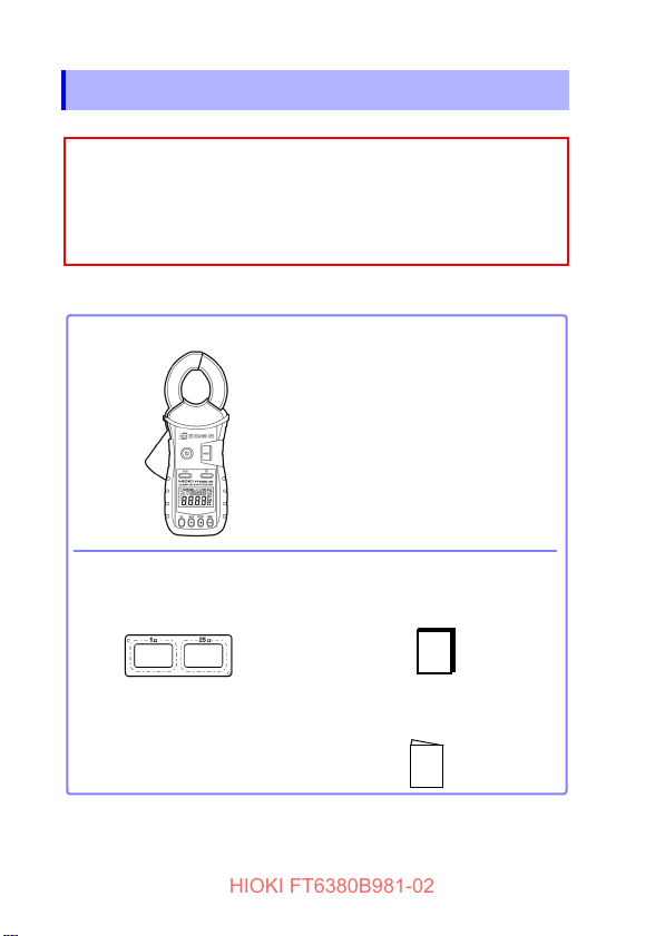
Verifying Package Contents
When you receive the instrument, inspect it carefully to ensure
that no damage occurred during shipping. In particular, check
the accessories, panel switches, and connectors. If damage is
evident, or if it fails to operate according to the specifications,
contact your authorized Hioki distributor or reseller.
□ FT6380-50 Clamp on Earth Tester
□ Instruction Manual (this manual)
□ Carrying case
□ Resistance check loop
(1 Ω ±2%, 25 Ω ±1%)
□ LR6 Alkaline battery ×2
□ Strap
□ Operating Precautions
(0990A907)
HIOKI FT6380B981-02
2
Verifying Package Contents
Confirm that these contents are provided.
Accessories
Use the original packing materials when transporting the instrument, if
possible.
For other transportation notes, refer to the “Transporting” (p.66).
Page 7
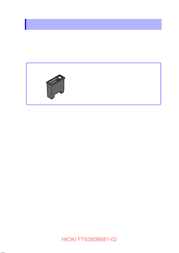
Option (sold separately)
□ Z3210 Wireless Adapter
HIOKI FT6380B981-02
Option (sold separately)
The option listed below is available for the instrument. To order
an option, please contact your authorized Hioki distributor or
reseller. Options are subject to change. Check Hioki’s website
for the latest information.
3
Page 8
Safety Information
HIOKI FT6380B981-02
4
Safety Information
This instrument is designed to conform to IEC 61010 Safety
Standards and has been thoroughly tested for safety prior to
shipment. However, using the instrument in a way not described
in this manual may negate the provided safety features. Carefully read the following safety notes before using the instrument.
Mishandling instrument could result in bodily injury or
even death, as well as damage to the instrument.
Familiarize yourself with the instructions and precautions
in this manual before use.
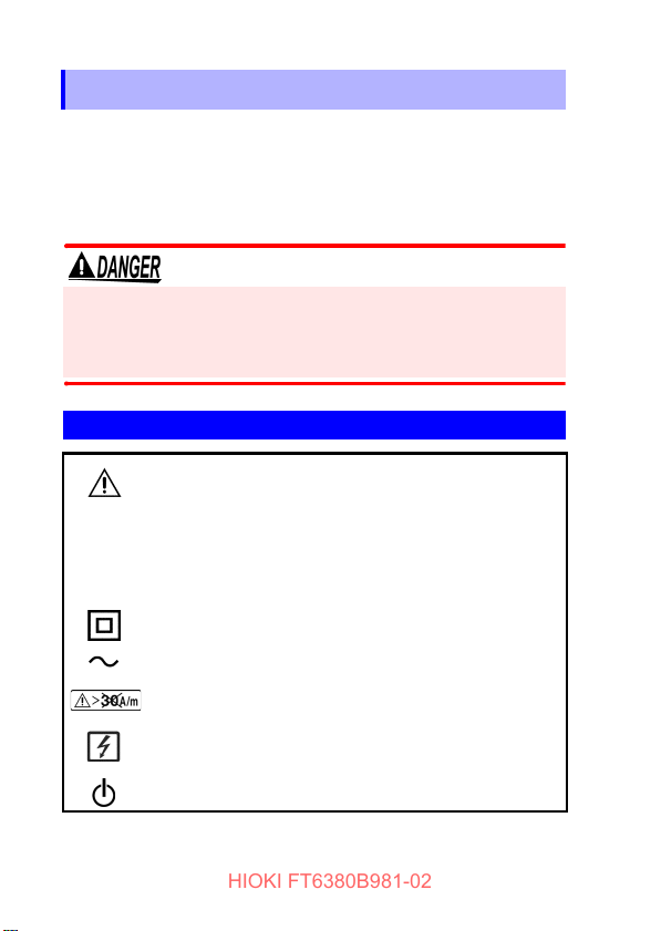
Symbols on equipment
Indicates the need for caution or the presence of a
hazard. For more information about locations
where this symbol appears on instrument components, see “Operating Precautions” (p.8), warning
messages listed at the beginning of operating
instructions, and the document entitled “Operating
Precautions” that comes with the instrument.
Indicates a double-insulated device.
Indicates AC (Alternating Current).
Indicates that using the instrument in an external
magnetic field of exceeding 30 A/m is prohibited.
Indicates that the instrument may be connected to
or disconnected from a live circuit.
Indicates whether the power is on or off.
Page 9

Safety Information
HIOKI FT6380B981-02
The following symbols in this manual indicate the relative importance of cautions and warnings.
Indicates an imminently hazardous situation
that, if not avoided, will result in death of or
serious injury to the operator.
Indicates a potentially hazardous situation that,
if not avoided, could result in death of or serious injury to the operator.
Indicates a potentially hazardous situation that,
if not avoided, could result in minor or moderate injury to the operator.
IMPORTANT
Indicates information or content that is particularly important from the standpoint of operating
or maintaining the instrument.
Indicates the possibility of equipment damage.
Symbols for Various Standards
Indicates the Waste Electrical and Electronic
Equipment Directive (WEEE Directive) in EU
member states.
Indicates that the instrument complies with standards imposed by EU directives.
Other Symbols
5
(p. #)
[ ] Information displayed on the screen is enclosed
Indicates a prohibited action.
Indicates the location of reference information.
in brackets.
Page 10
Safety Information
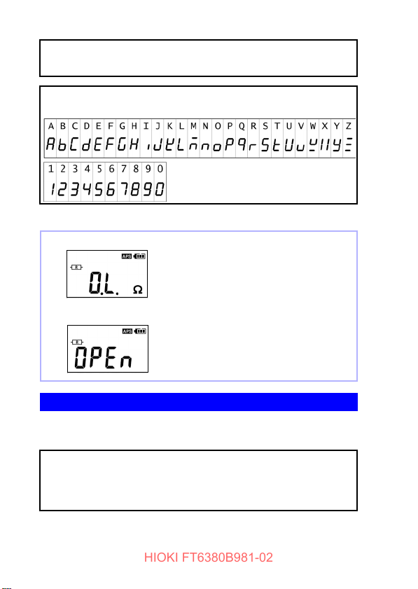
Over-range display
Open display
Resistance measurement: When the reading exceeds 1,600 Ω
Current measurement: When the reading
exceeds 60.0 A.
This screen is displayed when the clamp
sensor is not completely closed during use
of the resistance measurement function.
HIOKI FT6380B981-02
6
Fn
(bold
characters)
Bold text indicates alphanumeric characters
shown on operation keys.
The screen of this instrument displays characters in the following manner.
Screen displays that differ from the above notation:
Symbols for Various Standards
Hioki expresses accuracy as error limit values specified in terms
of percentages of reading.
Reading
(displayed
value)
Refers to the displayed value of the measuring instrument. The limit values of reading
errors are expressed in percent of reading
(% of reading, % rdg).
Page 11
Safety Information
HIOKI FT6380B981-02
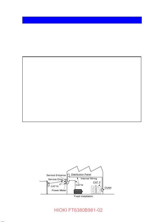
Measurement categories
This instrument complies with CAT IV safety requirements.
To ensure safe operation of measurement instruments IEC
61010 establishes safety standards for various electrical environments, categorized as CAT II to CAT IV, and called measurement categories.
Primary electrical circuits in equipment connected
CAT II
CAT III
CAT IV
Using a measurement instrument in an environment designated
with a higher-numbered category than that for which the instrument is rated could result in a severe accident, and must be
carefully avoided.
Use of a measurement instrument that is not CAT-rated in CAT II
to CAT IV measurement applications could result in a severe
accident, and must be carefully avoided.
to an AC electrical outlet by a power cord (portable
tools, household appliances, etc.)
CAT II covers directly measuring electrical outlet
receptacles.
Primary electrical circuits of heavy equipment
(fixed installations) connected directly to the distribution panel, and feeders from the distribution
panel to outlets.
The circuit from the service drop to the service
entrance, and to the power meter and primary
overcurrent protection device (distribution panel).
7
Page 12
Operating Precautions
HIOKI FT6380B981-02
8
Operating Precautions
Follow these precautions to ensure safe operation and to obtain
the full benefits of the various functions.
Use of the instrument should confirm not only to its specifications, but also to the specifications of all accessories, options,
batteries, and other equipment in use.
Preliminary Checks
Before using the instrument for the first time, verify that it operates normally to ensure that no damage occurred during storage
or shipping. If you find any damage, contact your authorized
Hioki distributor or reseller.
Instrument Installation
Operating temperature: -10°C to 50°C (14°F to 122°F)
(Be sure to use batteries that are suited for use under the environmental conditions in which you are using the instrument.)
Operating humidity: 80% RH or less (non condensating)
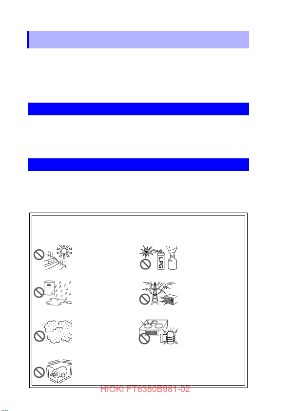
Avoid the following locations that could cause an accident or
damage to the instrument.
Exposed to direct
sunlight
Exposed to high temperature
Exposed to water, oil,
other chemicals, or
solvents Exposed to
high humidity or condensation
Exposed to high levels of particulate dust
In the presence of corrosive or explosive
gases
Exposed to strong
electromagnetic fields
Near electromagnetic
radiators
Near electromagnetic
radiators (e.g., highfrequency induction
heating systems and
IH cooking utensils)
Subject to vibration
Page 13

Operating Precautions
HIOKI FT6380B981-02
Handling the Instrument
• To avoid short circuits and potentially life-threatening
hazards, never attach the clamp to a circuit that operates
at more than 600 V AC, or over bare conductors.
• The maximum rated voltage between input terminals and
ground is 600 V AC. Measuring a voltage in excess of this
rating relative to ground could damage the instrument
and result in bodily injury.
• To avoid electric shock, do not remove the instrument's
case. The internal components of the instrument carry
high voltages and may become very hot during operation.
• When the clamp sensor is opened, do not allow the metal
part of the clamp sensor to touch any exposed metal, or
to short between two lines, and do not use over bare conductors.
To avoid electric shock when measuring live lines, wear
appropriate protective gear, such as insulated rubber
gloves, boots and a safety helmet.
9
Page 14

Operating Precautions
Frequency [Hz]
Current [A]
HIOKI FT6380B981-02
10
• Do not input a current in excess of the maximum allowable
current. Doing so may damage the instrument or cause burns.
The maximum allowable current is 100 A AC continuous or
200 A AC within 2 minutes at 50 Hz/60 Hz. For more information about the frequency derating characteristics during continuous input, see the following diagram:
• To avoid damage to the instrument, protect it from physical
shock when transporting and handling. Be especially careful
to avoid physical shock from dropping.
• Be careful to avoid dropping the instrument or otherwise subjecting them to mechanical shock, which could damage the
mating surfaces of the core and adversely affect measurement.
• Although this instrument is dust resistant, it is not completely
dust- or waterproof. To prevent possible damage, avoid using
in dusty or wet environments.
• Do not slant the instrument or place it on top of an uneven surface. Dropping or knocking down the instrument can cause
injury or damage to the instrument.
Page 15

Operating Precautions
HIOKI FT6380B981-02
• The protection rating for the enclosure of the instrument
(based on EN 60529) is IP40*. (The rating applies to the
clamp sensor when in the closed position.)
*: IP40
This indicates the degree of protection provided by the enclosure of the device against use in hazardous locations, entry of
solid foreign objects, and the ingress of water.
4: Protected against access to hazardous parts with wire mea-
suring 1.0 mm in diameter. The equipment inside the enclosure is protected against entry by solid foreign objects larger
than 1.0 mm in diameter.
0: The equipment inside the enclosure is not protected against
the harmful effects of water.
11
Page 16

Operating Precautions
HIOKI FT6380B981-02
12
Page 17

1.1 Product Overview
HIOKI FT6380B981-02
13
Overview Chapter 1
1.1 Product Overview
The FT6380-50 Clamp on Earth Tester makes grounding resistance measurements simply by being clamped to multiplegrounded ground wires. No auxiliary grounding rod is needed,
and there is no need to disconnect the ground wire from the
grounding rod.
The instrument also provides AC current measurement functionality and can measure currents ranging from leakage current on
the order of several mA to load currents of up to 60 A.
Page 18

1.2 Features
HIOKI FT6380B981-02
14
1.2 Features
Compact, low-profile sensor
The compact, low-profile sensor can be used to clamp ground wires
with ease. The sensor design dramatically speeds the measurement
process by eliminating the need to pull out ground wires for clamping
or dig around the ground rod or wire.
Broad dynamic range
The instrument can easily measure grounding resistance of up to
0.02 Ω to 1,600 Ω with its auto-range function. Current measurement
ranges from small leakage current (maximum resolution 10 μA) to a
maximum of 60 A.
Noise check function (p.31)
The instrument automatically detects noise that may affect grounding resistance measurement and displays a [ ] mark.
True RMS display
True RMS calculation allows the instrument to accurately measure
distortion waveform currents.
Data hold function (p.37)
A large button that is easy to push lets you hold the measured value.
The button notifies the user of the hold status by lights up while the
value is being held.
Backlight function (p.37)
The instrument uses a white LED for excellent visibility so that display values can be read clearly, even in dark locations.
Auto-power-save (APS) function (p.54)
An auto-power-save function keeps batteries from running down
when you forget to turn off the instrument.
Page 19

1.2 Features
HIOKI FT6380B981-02
15
Alarm function (p.39)
By setting a threshold, you can have the instrument make a PASS/
FAIL judgment and notify you of the result with a buzzer. You can set
threshold values as you prefer for each resistance and current and
choose between two judgment conditions: when the measured value
exceeds the threshold (High) and when it falls below the threshold
(Low).
Filter function (p.38)
Widespread use of switching power supplies and inverters has led to
cases where harmonic components are superimposed on leakage
current waveforms. The instrument’s filter function allows it to perform two types of measurement: leakage current as related to degradation of insulation, and leakage current including this harmonic
component.
Internal memory (p.42)
The instrument’s internal memory can record up to 2,000 measured
values.
Automatic measurement report function using your
mobile communication device (p.46)
The wireless communication function enables your mobile communication device to create measurement reports on-site easily.
Page 20
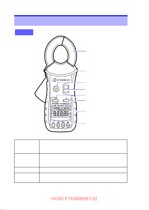
1.3 Names and Functions of Parts
Barrier
Front
Clamp sensor
Power key
HOLD key (p.37)
A/Ω key
Backlight key (p.37)
Display indicator (p.19)
Operation key (p.18)
HIOKI FT6380B981-02
16
1.3 Names and Functions of Parts
Power key • Used to turn the instrument on and off.
HOLD key • Holds the measured value display or cancels hold mode.
Backlight key • Turns the backlight on and off.
A/Ω key • Switches between resistance measurement mode and
• To temporarily cancel the auto-power-save function,
press the power key while holding down the HOLD key.
• To cancel auto-power-save mode, press the power key
while holding down the HOLD key.
current measurement mode.
Page 21

Battery cover (p.23)
Back
Strap hole
(p.22)
Bottom
Serial No.
The serial number consists of nine
digits. The first two digits indicate
the year of manufacture, while the
second two digits indicate the month
of manufacture.
Do not remove this sticker as the
number is important.
HIOKI FT6380B981-02
1.3 Names and Functions of Parts
17
Page 22
1.3 Names and Functions of Parts
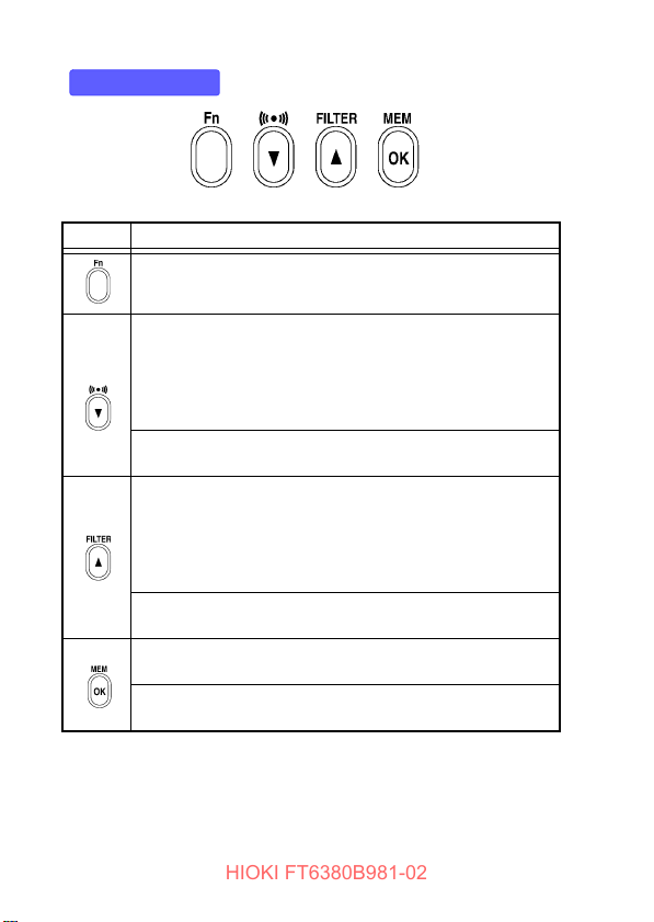
Operation key
HIOKI FT6380B981-02
18
Key Description
Switches to function mode, which is used to configure settings. Pressing this key again will return to resistance measurement mode or current measurement mode. (p.51)
• Enables the alarm function. (p.39)
• When the alarm function is enabled, the instrument will
notify the user with the buzzer if a reading is greater than (or
less than) a preset threshold.
• Alarm function threshold settings can be configured in function mode. (p.41)
*In function mode, this key serves as the
used to select setting items and values.
• Pressing this key while using the current measurement function enables the low-pass filter to reject unneeded harmonic
components. (p.38)
• Pressing it while using the resistance measurement function
enables the moving average function, allowing more stable
measurement. (p.38)
*In function mode, this key serves as the
used to select setting items and values.
Saves measurement data to the instrument’s internal memory. (p.42)
*In function mode, this key serves as the
used to accept setting items and values.
▼ key, which is
▲ key, which is
OK key, which is
Page 23
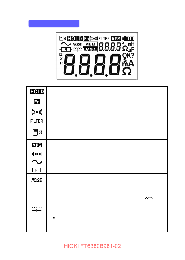
Display Indicators
HIOKI FT6380B981-02
1.3 Names and Functions of Parts
Lights up when data is being held. (p.37)
Lights up in function mode. (p.51)
Flashes in subfunction mode. (p.52)
Lights up when the alarm function is on. (p.39)
Lights up when the filter function is on. (p.38)
Lights up when the wireless communication function is on.
Flashes when data is being sent or received. (p.46)
Lights up when the auto-power-save function is on. (p.54)
Indicates the remaining battery power. (p.23)
Lights up in AC current measurement mode. (p.33)
Lights up in resistance measurement mode. (p.29)
Lights up in resistance measurement mode when a current
that could affect the measured value is detected. (p.31)
Lights up in resistance measurement mode when the measured ground loop has a high reactance component or capacitance component (
lights up due to a low measured resistance value, it is likely
that the displayed value indicates a shorted measurement
loop rather than normal grounding resistance. When the
] mark lights up, the loop may have a break in it. In this
[
case, the mark indicates that the wires have been coupled by
capacitance.) (p.32)
±45° or greater). (When the [ ] mark
19
Page 24

1.3 Names and Functions of Parts
HIOKI FT6380B981-02
20
Lights up during internal memory operations. (p.42)
The number of measurement data points stored in memory is
shown to the right.
Lights up when the range display function is on.
The measurement range is shown to the right.
Page 25

Measurement Chapter 2
Measurement
Resistance Measurement (p.29)
Current Measurement (p.33)
End of measurement
Remove the instrument from the measurement target.
Turn off the instrument.
Measurement Preparations
Pre-Operation Inspection (p.26)
Using the included resistance check loop to inspect the
instrument (p.27)
3
2
1
HIOKI FT6380B981-02
2.1 Measurement process
2.1 Measurement process
21
Page 26

2.2 Preparing for Measurement
HIOKI FT6380B981-02
22
2.2 Preparing for Measurement
After purchasing the instrument
Complete the following steps before using the instrument to
make measurements.
Attaching the Strap
Attach both ends of the Strap securely to the instrument.
If insecurely attached, the instrument may fall and be damaged
when carrying
Thread the strap through the strap hole as shown in the following diagram:
Page 27

2.2 Preparing for Measurement
HIOKI FT6380B981-02
23
Installing (or Replacing) the Battery and Wireless
Adapter
Before using the instrument for the first time, install two LR6
Alkaline batteries.(p.25) Verify that there is sufficient battery
power remaining before measurement. If there is insufficient battery power remaining, replace the batteries.
Battery Status Indicator
This indicator is displayed at the top right corner.?
When new alkaline batteries have been installed
When 2/3 of the battery power remains
When 1/3 of the battery power remains
No battery power remains. Replace with new batteries.
When the Z3210 Wireless Adapter (option) is installed, the wireless communication function can be used.(p.46)
• To avoid electric shock, disconnect the clamp from the
measuring object before removing the battery cover.
• After replacing the batteries or after installing or removing the Z3210, install the battery cover and tighten the
screws before use.
• Battery may explode if mistreated. Do not short- circuit,
recharge, disassemble or dispose of in fire.
• Handle and dispose of batteries in accordance with local
regulations
• To prevent instrument damage or an electric shock, use
only the screws that are originally installed for securing
the battery cover in place. If you have lost a screw or find
that a screw is damaged, please contact your authorized
Hioki distributor or reseller.
Page 28

2.2 Preparing for Measurement
HIOKI FT6380B981-02
24
• Do not mix old and new batteries, or different types of batteries. Also, be careful to observe battery polarity during installation. Otherwise, poor performance or damage from battery
leakage could result.
• To avoid corrosion from battery leakage, remove the batteries
from the instrument if it is to be stored for a long time.
• After touching any metallic part, such as a doorknob, to eliminate static electricity from your body, connect/disconnect the
Z3210. Failure to do so could cause static electricity to damage the Z3210.
•
The [ ] indicator lights when battery voltage becomes
low. Replace the batteries as soon as possible.
• Before replacing the batteries, make sure to turn off
the instrument.
• After use, always turn off the instrument.
• If the battery is completely exhausted, the display will
show [
bAtt → P.oFF], and the instrument will automati-
cally turn off.
Page 29

Installing (replacing) the batteries and wireless adapter
2
3
5
6
7
4
Rear
Prepare the following.
• LR6 Alkaline battery ×2
• Z3210 Wireless Adapter (option)
• Phillips screwdriver
HIOKI FT6380B981-02
Start the following procedure after reading the safety precautions.(p.23)
Disconnect the instrument from the measuring object
1.
and turn off the power.
Loosen the screws and remove the battery cover.
2.
Remove the old batteries (when replacing the batteries).
3.
Install new batteries, taking care to orient them properly.
4.
When installing the wireless adapter, remove the pro-
5.
tective cap.
Insert the wireless adapter all the way inside while
6.
carefully checking its orientation.
Install the battery cover and tighten the screws.
7.
2.2 Preparing for Measurement
25
Page 30

2.3 Pre-Operation Inspection
Before using the instrument for the first time, verify that it operates normally to ensure that no damage occurred during storage or shipping. If you find any damage, contact your
authorized Hioki distributor or reseller.
Does the screen turn on when
the instrument is turned on?
The batteries may be dead.
Replace the batteries and try
again.
The instrument may be malfunctioning. Have the instrument repaired.
• Is the instrument damaged?
• Is the clamp sensor cracked
or otherwise damaged?
No
End of inspection
Yes
An error is
displayed.
• The screen is not on.
• The screen shows an
error.
Do not use the instrument if it
is damaged as doing so may
result in electric shock. Have
the instrument repaired.
Yes
1. Inspecting the instrument
2. Inspecting the instrument after turning it on
The screen is on.
Using the included resistance
check loop to inspect the instrument (p.27)
HIOKI FT6380B981-02
26
2.3 Pre-Operation Inspection
Page 31

2.3 Pre-Operation Inspection
Resistance check loop
HIOKI FT6380B981-02
27
Using the included resistance check loop to
inspect the instrument
Before turning on the instrument, be sure to read Operating Precautions (p.8).
Inspecting the instrument with the resistance check loop
Verify that there is no foreign matter lodged between the tips of
the clamp sensor and that the sensor can be closed and opened
smoothly. If so, clamp the included resistance check loop and
verify that the instrument is operating properly. Verify that a
value within the allowable range is displayed for each loop.
Test resistance Allowable range
1 Ω 0.95 Ω to 1.05 Ω
25 Ω 24.3 Ω to 25.7 Ω
• If the instrument displays a value outside the allowable
range, it needs to be repaired. Contact your authorized
Hioki distributor or reseller.
• The resistance check loop cannot be used to calibrate
the instrument. To have the instrument calibrated, contact your authorized Hioki distributor or reseller.
Page 32

2.4 Measurement Procedure
barrier
HIOKI FT6380B981-02
28
2.4 Measurement Procedure
• To avoid electric shock, do not touch the portion beyond the protective barrier during use.
• When the clamp sensor is opened, do not
allow the metal part of the clamp sensor to
touch any exposed metal, or to short
between two lines, and do not use over bare
conductors.
• The maximum allowable current is 100 A AC continuous
or 200 A AC for 2 minutes (50 Hz/60 Hz). Currents in
excess of these values must be avoided as they may damage the instrument or cause bodily injury.
• The tips of the clamp sensor are precisely manufactured in order to provide a high level of precision. Exercise caution when handling the clamp so as to avoid
subjecting it to excessive vibration, mechanical shock,
or force.
• If foreign matter gets stuck between the tips of the
clamp sensor, do not forcibly open or close the sensor,
but rather use a soft brush or similar implement to
carefully remove the foreign matter. Accurate measurements cannot be made while foreign matter is
stuck between the tips of the clamp sensor or while the
shape of the clamp sensor is deformed. If the tips of
the clamp sensor become deformed, have the instrument inspected and calibrated by your authorized
Hioki distributor or reseller.
Page 33

2.4 Measurement Procedure
RmR
x
1
1
R
i
-----
i 1=
n
------------
+=
R
x
1
1
R
i
-----
i 1=
n
------------------
«
R
x
R
1
R
n
R
2
HIOKI FT6380B981-02
29
Resistance Measurement
Measuring Principle
As illustrated below, the instrument is designed to measure
grounding resistance at multiple grounding locations. (*For applications involving the measurement of grounding resistance at a
single grounding site, use Hioki FT6031-50 Earth Tester or Hioki
FT3151 Analog Earth Tester.)
If the grounding resistance of the measurement target is represented by R
grounded locations are represented by R
tance value measured by the product is as follows:
If n is sufficiently large and each Ri value is sufficiently small,
and the grounding resistance values of other
x
, R2, …, Rn, the resis-
1
and the second term can be ignored, allowing the value of
Rx to be measured.
Page 34

2.4 Measurement Procedure
R
x
R
1
R
n
R
x
HIOKI FT6380B981-02
30
Example with actual measured values
The following provides an example with actual measured values.
The more grounding electrodes there are in the multiplegrounded installation, the higher the accuracy of the obtained
values. Alternately, if even one grounding electrode has a small
value (for example, 1 Ω), accurate values can be approached
even if there are few grounding electrodes. Since most multiplegrounded systems have a large number of grounding electrodes, the error can be limited.
Measuring method
Select resistance measurement mode.
1.
Select resistance measurement mode with the A/Ω key.
Clamp the grounding wire you wish to measure.
2.
The resistance value will be displayed.
Page 35

2.4 Measurement Procedure
HIOKI FT6380B981-02
• Do not measure the same location with two or more
Clamp on Earth Testers at the same time. The instruments will interfere with each other, preventing accurate measurement.
• Verify that the [ ] mark is not lit up.
When the current flowing through the grounding wire is
high (approximately 2.5 A or greater with a commercial
frequency of 50 Hz/60 Hz, approximately 100 mA or
greater with a harmonic component of 1 kHz), the current will affect measured values, making it impossible
to measure the resistance. Check the current flowing
through the grounding wire.
* The current level at which the [ ] mark lit up
depends on individual differences as well as the frequency. The closer to the injected signal frequency,
the smaller the noise current that will affect operation.
• Open display
The screen will show [OPEn] if the clamp sensor is not
completely closed. Close the clamp sensor completely
and repeat the measurement.
* If an extremely large current is flowing through the
grounding wire or a DC current is superposed, the
screen may display [OPEn] even if the clamp sensor
is completely closed. This does not signal a malfunction. Check the current flowing through the grounding
wire by using the instrument's current measurement
mode or an instrument such as a clamp tester capable of DC current measurement.
31
Page 36

2.4 Measurement Procedure
R
x
R
x
R
x
R
1
R
x
R
1
[]
[]
Short
Break
HIOKI FT6380B981-02
32
• Inductor mark
If the [ ] mark next to the resistance mark light up
during measurement, there may be a short in the
ground wire. It is recommended to verify that there are
no shorts in the location being measured.
• Capacitance mark
[]
If the
during measurement, there may be a break in the
ground wire. It is recommended to verify that there are
no wiring breaks in the location being measured.
mark next to the resistance mark light up
Page 37

2.4 Measurement Procedure
HIOKI FT6380B981-02
33
Current Measurement
Measuring Principle
The instrument is designed based on the principle of electromagnetic induction. The magnetic field corresponding to the current flowing through the conductor to be measured is detected
by a current transformer that consists of a magnetic core and
coil. The current transformer generates the current corresponding to the magnetic field. The detection resistor converts this current into the voltage to calculate the value of the current flowing
through the conductor.
Measuring method
Select current measurement mode with the A/Ω key.
1.
Position the conductor in the center of the clamp
2.
sensor.
To perform measurement accurately, place the conductor to pass through the center of the clamp sensor at a
right angle.
Page 38

2.4 Measurement Procedure
OK NG
HIOKI FT6380B981-02
34
The current RMS value will be shown on the display.
• Always clamp the instrument around only one conductor. Clamping the instrument around two or more of
conductors in a bundle prevents the instrument from
measuring any current regardless of whether the measurement target is a single-phase or three-phase circuit.
• The frequency of special waveforms such as at the
secondary side of an inverter may not be indicated correctly.
• Depending on the magnitude and frequency of the
input current, resonances may be heard from the
clamp jaw. This does not affect the measurement.
• Do not input a current in excess of the maximum allowable current for the current range being used.
• Displayed values can frequently fluctuate due to
induction potential even when no voltage is applied.
This, however, is not a malfunction.
Page 39

Measuring zero-phase current
Single-phase, 2-lead circuits
three-phase 3-lead circuits
Clamp all three leads of
the circuit.
Load
device
Load
device
lg
HIOKI FT6380B981-02
When measuring zero-phase current, clamp all of the circuits at
once.
2.4 Measurement Procedure
35
Page 40

2.4 Measurement Procedure
HIOKI FT6380B981-02
36
Do not input current that exceeds the maximum continuous input of the electric current range.
• Measurement may not be accurate in the cases below.
(1) When there is large current (of about 100 A) flow-
ing through a nearby electric line
(2) Note that a value of several tens of amperes may
be displayed when opening or closing the clamp
sensor, or when changing the electric current
range. This is not an error. It may take some time
for the display to return to zero. However, starting
measurement before the display returns to zero will
not affect measurement.
• Enable the “Filter function (Rejecting noise) (p.38)”
when conducting measurement in the cases below.
(1) When meaningless data is displayed due to noise.
(2) When using the instrument to measure special
waveforms, such as those on the secondary side of
an inverter
• The instrument may not be able to perform measurement in the cases below.
(1) When using input current that is 1/10 or less of the
full electric current range
(2) When measuring high frequencies with the filter
function enabled.
Page 41

2.5 Convenient function
HIOKI FT6380B981-02
37
2.5 Convenient function
Data hold function (Holding the measured value)
This function holds the measured value and continues to display
that value.
Press the HOLD key. The [ ] mark will be displayed, and
the measured value will be held. The HOLD key will lights up. To
cancel hold mode, press the HOLD key again. The [ ] mark
will disappear, and the HOLD key will turn off.
Backlight function
(Making measurements in a dark location)
This function makes the display easier to see in dark locations.
Press the backlight key ( ). The backlight will turn on.
The backlight will turn off automatically when there has been no
operation for about 2 minutes.
To turn off the backlight, press the backlight key ( ) again. The
backlight will turn off.
Page 42

2.5 Convenient function
HIOKI FT6380B981-02
38
Filter function (Rejecting noise)
This function allows you to reject unneeded frequency components such as high-frequency noise.
Press the FILTER key. The [ ] mark will be displayed. To
cancel the filter, press the FILTER key again. The [ ] mark
will disappear.
During resistance measurement
Using the filter function when there is a significant amount
of variation in measured values during resistance measurement will cause the measured values to stabilize.
*Note that noise rejection cannot be used when the [
mark is lit up.
During current measurement
Using the filter function enables a low-pass filter, causing
the harmonic component to be eliminated from measured
values. Widespread use of switching power supplies and
inverters has led to cases where harmonic components are
superimposed on current waveforms; the filter function is
effective in such cases. Canceling the filter function disables the low-pass filter, allowing measurement of current
including harmonic components.
]
Page 43

2.5 Convenient function
Alarm settings screen for resistance measurement
Alarm settings screen for current measurement
HIOKI FT6380B981-02
39
Alarm function
(Judging measured values and sounding an alarm)
You can sound an alarm using previously set thresholds by
pressing the key. A high tone signifies a high alarm, while
a low tone signifies a low alarm.
Thresholds and other settings must be configured in advance.
To cancel the alarm function, press the key again.
Configuring the alarm settings
1.
Press the Fn key to switch to function mode. Using the ▼
and ▲ keys, select the resistance or current alarm settings
screen and press the OK key.
*For more information about function mode, see (p.51).
Page 44

2.5 Convenient function
Lo: The alarm will sound if the measured value
is less than the set threshold value.
Hi: The alarm will sound if the measured value
is greater than the set threshold value.
*The Hi/Lo setting is saved once the following setting has been
configured. If you press the
Fn key after configuring the Hi/Lo set-
ting but before saving the threshold and thereby cancel the configuration process, any changes to the Hi/Lo setting will not be
saved.
HIOKI FT6380B981-02
40
Set the alarm type (Hi/Lo).
2.
Using the ▼ and ▲ keys, select the alarm type (Hi/Lo),
and press the OK key. The next threshold setting will start
flashing.
Page 45

2.5 Convenient function
HIOKI FT6380B981-02
Set the threshold.
3.
After configuring the Hi/Lo setting, set the threshold.
Using the ▼ and ▲ keys, set the threshold and press the
OK key.
You can move more quickly through threshold values by
pressing and holding the ▼ and ▲ keys.
Once the settings are complete, the screen will switch to
the alarm settings screen. To return to resistance measurement or current measurement mode, press the Fn
key again or the A/Ω key.
41
Page 46

2.5 Convenient function
Memory number
When the number of values saved in the instrument’s memory
reaches 2,000, the display will show “FULL,” and you will not
be able to save additional values. Delete unneeded values to
free up space.
HIOKI FT6380B981-02
42
Memory function (Saving measurement data)
Press the MEM key in either resistance measurement mode or
current measurement mode. The instrument will beep three
times and the displayed measured value will be stored along
with the memory number (1 to 2000) in the instrument’s internal
memory.
* Measured values, filter use, and the [ ] and [ ]
marks are saved in memory.
Page 47

2.5 Convenient function
HIOKI FT6380B981-02
Loading a value from the instrument’s internal memory
Press the Fn key to enter function mode.
1.
* For more information about function mode, see (p.51).
Using the ▼ and ▲ keys, select the read memory
2.
screen and press the OK key.
Using the ▼ and ▲ keys, increment or decrement the
3.
memory number to recall the measured value for the
memory number you wish to load.
You can move more quickly through memory numbers
by pressing and holding the ▼ and ▲ keys.
To exit the read memory screen, press the Fn key or the
OK key.
* To return to resistance measurement or current mea-
surement mode, press the Fn key again or the A/Ω
key.
43
Page 48

2.5 Convenient function
To clear the last stored data point
(1 value)
(The screenshot to the left indicates
that 34 values have been saved in
the instrument’s memory.)
To clear all data points
(The screen will show [ALL].)
HIOKI FT6380B981-02
44
Clearing stored data
You can clear the last stored data point (1 value) or all
stored data points.
Press the Fn key to enter function mode.
1.
* For more information about function mode, see (p.51).
Using the ▼ and ▲ keys, select the Clear Memory
2.
screen and press the OK key. The screen will show
[CLr].
Using the ▼ and ▲ keys, select either the last stored
3.
data point or all data points and press the OK key.
The [OK?] mark will flash on the LCD once you select
the data to clear so that you can confirm your intentions.
Press the OK key again to clear the data.
Page 49

2.5 Convenient function
HIOKI FT6380B981-02
• To cancel, press the Fn key.
• To return to resistance measurement or current mea-
surement mode, press the Fn key again or the A/Ω
key.
45
Page 50

2.5 Convenient function
GENNECT Cross Official Website
https://gennect.net/en/cross/index
HIOKI FT6380B981-02
46
Wireless Communication Function
(GENNECT Cross)
When the wireless communications function is enabled, you can
review measurement data and create measurement reports on
mobile devices.
For more information about this functionality, see “GENNECT
Cross Official Website” (application software, free of charge).
• The communication distance is approx. 10 m (line of
sight).The distance over which data can be sent and
received varies greatly depending on whether there
are any obstructions between the paired instruments
(for example, walls, metal barriers, etc.) and on the distance between the instrument and the floor (or
ground). To ensure stable communication, verify adequate signal strength.
• Although the GENNECT Cross is provided free of
charge, downloading or using the application software
may incur Internet connection charges. Such charges
are the sole responsibility of the user.
• The GENNECT Cross is not guaranteed to operate on
all mobile devices.
• The Z3210 uses 2.4 GHz band wireless technology. It
may not be possible for the device to establish a wireless connection when used in the vicinity of other
devices that use the same frequency band, for example Wi-Fi devices (IEEE 802.11.b/g/n).
• When the app is launched for the first time (before
being paired with any instrument), the instrument settings screen will be displayed.
Page 51

2.5 Convenient function
HIOKI FT6380B981-02
•
While the mobile device is displaying the GENNECT
Cross's instrument settings screen, simply move it close
to the instrument to automatically pair it with the instrument (the app can be paired with up to 8 instruments).
•
Allow about 5 s to 30 s for the instrument to pair with the
app after being turned on. If the instrument fails to pair
within 1 min., relaunch GENNECT Cross and cycle the
instrument’s power.
Connect the Z3210 Wireless Adapter (option) to the
1.
instrument. (p.23)
2. Install the GENNECT Cross on your mobile device.
3. Turn on the instrument.
Press the Fn key to enter function mode.
4.
*
For more information about function mode, see (p.51).
Using the ▼ and ▲ keys, select the wireless communi-
5.
cation setting screen and press the OK key.
* When the Z3210 is not connected, the instrument will
display [n.c.]. You cannot switch on/off the wireless
communication setting.
47
Page 52

2.5 Convenient function
Lights up: Wireless communication function is on.
Lights off: Wireless communication function is off.
Flashes: Performing wireless communication
mark
HIOKI FT6380B981-02
48
Using the ▼ and ▲ keys, select [on] and press the OK
6.
key to enable the wireless communication function.
Launch the GENNECT Cross and pair it with the instru-
7.
ment.
Select the measurement function and start measure-
8.
ment.
Page 53

2.5 Convenient function
Enter measured values.
HIOKI FT6380B981-02
49
Excel® Direct Entry Function (HID Connection)
Concurrent use of the GENNECT Cross and HID function is not
available.
The human interface device (HID) profile, with which the Z3210
Wireless Adapter is equipped, is a profile same as that wireless
keyboards use.
®
Preparatory to data entry, open an Excel
HID ON
HID OFF Choose this option to use GENNECT Cross.
The setting whether the HID function has been enabled or
disabled will not be saved in the instrument but in the Z3210.
deviceor computer and choose a cell. Freezing the
instrument’s display can enter the measured values on the
cells.
Turn off the instrument.
1.
Connect the Z3210 Wireless Adapter (option) into the
2.
instrument. (p.25)
Switch over the display to HID setting mode.
3.
While holding down the A/Ω key, turn on the instrument.
If the [---] strings is displayed, an old version of the firmware has been installed in the Z3210.
Update it to the latest version. Use version 1.8 or later of
GENNECT Cross to update.
file on your mobile
Page 54

2.5 Convenient function
The instrument will be
turned off automatically.
IMPORTANT
Suppose the wireless communication function has been disabled. In
that case, you cannot display the HID setting confirmation screen and
toggle the HID function. Instead, enable the wireless communication
setting first.(p.46)
To switch over from the HID function to GENNECT Cross
If you start GENNECT Cross without canceling the paring between
the mobile device and the instrument,
GENNECT Cross may not be able to recognize the instrument as a
connectible device. Follow the
procedure below to reconnect the instrument to GENNECT Cross.
1. Use the Bluetooth
®
setting of your mobile device to delete the in-
strument.
2. Disable the Z3210’s HID function. (p.49)
3. Use the Instrument Setting of GENNECT Cross to reconnect the
instrument.
For detail information, please visit the Z3210’s
website.
https://z3210.gennect.net
HIOKI FT6380B981-02
50
Choose between [oFF] and [on].
4.
Turn off the instrument, and then turn on the instrument
while holding down the A/Ω and Fn keys.
The HID setting will be toggled between on and off. After
displaying the following screens in turn, the instrument
will be turned off automatically.
Page 55

Function mode
Current alarm settings (p.39)
Loading values from memory (p.43)
Clearing data from the
instrument’s memory (p.44)
Resistance alarm settings (p.39)
2
3
1
While in function mode, the [ ]
mark will light up.
1.
Press the Fn key to enter function mode.
2.
Using the ▼ and ▲ keys, select the desired setting.
3.
Accept the setting with the OK
key.
Press the Fn key or the A/Ω key
to exit function mode.
Wireless communication
setting (p.46)
HIOKI FT6380B981-02
In function mode, the following settings and operations are available:
• Resistance alarm settings • Current alarm settings
• Loading values from memory • Clearing data from the instrument’s
• Wireless communication settings
memory
2.5 Convenient function
51
Page 56

2.6 Advanced Settings and Functions
Press the power key
while holding down the
Fn key.
1
2
HIOKI FT6380B981-02
52
2.6 Advanced Settings and Functions
Advanced settings can be configured in sub-function mode. In
sub-function mode, the following settings and operations are
available:
• Measurement range display setting (p.53)
• Auto-power-saving (APS) setting (p.54)
• System reset (to revert to factory settings) (p.55)
To enter sub-function mode, turn on the instrument by pressing
power
the
key while holding down the Fn key.
To exit sub-function mode, press the
instrument and then turn it back on.
power
key to turn off the
Page 57

2.6 Advanced Settings and Functions
HIOKI FT6380B981-02
53
Enabling/disabling the measurement range display
function
Press the
1.
The instrument will enter sub-function mode.
Using the ▼ and ▲ keys, select the range display setting
2.
screen and press the OK key.
Using the ▼ and ▲ keys, switch the range display function
3.
on or off and press the OK key.
power
key while holding down the Fn key.
The measurement range is displayed using values only.
(Example: 1,600 Ω range 1,600)
The units for the measurement range are the same as
for the displayed measured value.
Page 58

2.6 Advanced Settings and Functions
The APS function is enabled
when the screen shows [on].
HIOKI FT6380B981-02
54
Enabling/disabling the auto-power-saving (APS)
function
The auto-power-saving (APS) function prevents unintentional
battery consumption when you forget to turn off the instrument.
The APS function activates automatically when the instrument is
turned on. The instrument will automatically turn off once about
5 minutes pass without any operation (an alarm will sound for
about 10 seconds first).
Pressing any key while the alarm sounds will reset the time
before the instrument turns off to about 5 minutes.
You can restart the instrument by pressing the power key.
Press the
1.
The instrument will enter sub-function mode.
Using the ▼ and ▲ keys, select the APS setting screen
2.
and press the OK key.
Using the ▼ and ▲ keys, switch the APS function on or off
3.
and press the OK key.
When the APS function is disabled in sub-function mode,
APS will remain disabled when the instrument’s power is
cycled.
To disable APS temporarily
power
key while holding down the Fn key.
Page 59

2.6 Advanced Settings and Functions
HIOKI FT6380B981-02
Turn on the instrument by pressing the power key while
holding down the HOLD key to disable APS until the
next time the instrument’s power is cycled. The next
time the power is cycled, APS will be enabled (as long
as the APS setting is enabled in sub-function mode).
55
Reverting the instrument to factory settings
(system reset)
This section describes how to initialize the instrument’s settings.
All measurement data (up to 2,000 values) will be deleted.
Press the power key while holding down the Fn key.
1.
The instrument will enter sub-function mode.
Using the ▼ and ▲ keys, select the System Reset screen
2.
and press the OK key.
The [OK?] mark will flash.
Press the OK key again.
3.
The instrument will revert to the factory settings.
• If the System Reset screen is displayed by mistake,
cycle the instrument's power without pressing the OK
key. Instrument operation will be restored without a
system reset having been performed.
• For more information about how to clear previously saved
measurement data, see “Clearing stored data (p.44)”.
Page 60

2.6 Advanced Settings and Functions
HIOKI FT6380B981-02
56
Page 61

3.1 General Specifications
HIOKI FT6380B981-02
Specifications Chapter 3
3.1 General Specifications
57
Operating
environment
Operating
temperature
and humidity range
Storage
temperature
and humidity range
Dustproofness and
waterproofness
Standards Safety EN 61010
Power supply LR6 Alkaline battery ×2
Continuous
operating time
Dimensions Approx. 73W × 218H × 43D mm (2.87”W × 8.58”H × 1.69”D)
Maximum diameter
of measurable
conductor
Mass Approx. 620 g (21.9 oz) (excluding batteries)
Product warranty
period
Accessories Reference: p.2
Options Reference: p.3
Indoors, pollution degree 2, altitude up to 2000 m (6562 ft.)
-10°C to 50°C (14°F to 122°F), 80% RH or less
(non-condensing)
-20°C to 60°C (-4.0°F to 140°F), 80% RH or less
(non-condensation)
IP40 (EN 60529)
With clamp sensor closed.
EN 61557 (EN 61557-13, Class2, 30 A/m)
EMC EN 61326
Rated supply voltage: 1.5 V DC ×2
Maximum rated power: 450 mVA
When using two LR6 Alkaline batteries (reference value at 23°C)
• Approx. 40 hours
(25 Ω measurement, backlight off, Z3210 not installed)
• Approx. 35 hours
(25 Ω measurement, backlight off, Z3210 installed and wireless communication)
(excluding projections)
φ32 mm
3 years
Page 62

3.2 Input, Output, and Measurement Specifications
HIOKI FT6380B981-02
58
3.2 Input, Output, and Measurement
Specifications
-1. Basic specifications
Measurement
item
Input
specifications
Maximum rated
terminal-toground voltage
-2. Measurement specifications/
Accuracy specifications
Common measurement specifications
Accuracy
guarantee
conditions
Temperature
coefficient
Nominal
operating
ranges
Resistance measurement
Current measurement
Resistance range:
0.20 Ω/2.00 Ω/20.00 Ω/50.0 Ω/100.0 Ω/200.0 Ω/400 Ω/600 Ω/
1200 Ω/1600 Ω
Current range:
20.00 mA/200.0 mA/2.000 A/20.00 A/60.0 A
Range switching: Auto range
600 V AC (Measurement category IV)
Anticipated transient overvoltage 8000 V
Accuracy guarantee period: 1 year
(Clamp sensor opening/closing count: Up to 10000 cycles)
Accuracy guarantee period after adjustment made by Hioki: 1 year
Accuracy guarantee temperature and humidity range:
23°C ±5°C, 80% RH or less
(Measurement accuracy × 0.1)/°C i s added to the measurement
accuracy
(Specified outside a range of 23°C ±5°C)
Operating temperature and humidity range:
See “Operating temperature and humidity range” in “General
Specifications” (p.57).
Position (Reference position):
The measurement target must be placed to pass through the
clamp sensor’s center perpendicularly to the clamp sensor.
Battery voltage:
Available effective battery voltage 2.3 V ±0.19 V to 3.45 V
Earth potential: 3 V rms (Direct current or sinusoidal wave)
External magnetic field:
400 A/m or less
(DC and frequency 50 Hz/60 Hz)
30 A/m or less
(AC current measurement only, frequency 15 Hz to 400 Hz
(excluding 50 Hz/60 Hz))
Page 63

3.2 Input, Output, and Measurement Specifications
HIOKI FT6380B981-02
Resistance measurement
Accuracy
guarantee
conditions
Measurement
Method
Effective
measuring range
Zero display
range
Overrange Greater than 1600 Ω
Injected signal
frequency
Injected voltage
level
Measurement
response time
No reactance component, no noise current, earth potential 0 V
Analog synchronous detection method (effective resistance mea-
surement)
0.02 Ω to 1600 Ω
Less than 0.02 Ω
2375 Hz ±25 Hz
9.0 mV ±1.0 mV rms (with load open)
Filter: OFF: 3 s ±0.5 s or less
Filter: ON: 9 s ±0.5 s or less
59
Range
(Accuracy Range)
0.20 Ω (0.02 Ω to 0.20 Ω)0.01 Ω ±1.5% rdg±0.02 Ω
2.00 Ω (0.18 Ω to 2.00 Ω)0.01 Ω ±1.5% rdg±0.02 Ω
20.00 Ω (1.80 Ω to 20.00 Ω)0.01 Ω ±1.5% rdg±0.05 Ω
50.0 Ω (18.0 Ω to 50.0 Ω)0.1 Ω ±1.5% rdg±0.1 Ω
100.0 Ω (50.0 Ω to 100.0 Ω)0.1 Ω ±1.5% rdg±0.5 Ω
200.0 Ω (100.0 Ω to 200.0 Ω)0.2 Ω ±3.0% rdg±1.0 Ω
400 Ω (180 Ω to 400 Ω)1 Ω ±5% rdg±5 Ω
600 Ω (400 Ω to 600 Ω)2 Ω ±10% rdg±10 Ω
1200 Ω (600 Ω to 1200 Ω)10 Ω ±20% rdg
1600 Ω (1200 Ω to1600 Ω)20 Ω ± 35% rdg
To obtain the measurement accuracy at a range boundary, apply the accuracy of the
higher-accuracy range.
Resolution
Accuracy
(Intrinsic uncertainty A)
Page 64

3.2 Input, Output, and Measurement Specifications
HIOKI FT6380B981-02
60
Items involved in EN 61557-5
Measurement waveform Sinusoidal wave (with a distortion factor of 5% or less)
Effect of positioning (E1) Accuracy × 2.0
Effect of supply voltage
(E2)
Effects of temperature
(E3)
Series disturbance
voltage (E4)
Fiducial resistance 100 Ω
Allowable ground
potential
Effects of resistance
of the auxiliary earth
electrodes (E5)
Effects of system
frequency (E7)
Effects of system
voltage (E8)
Operation uncertainty ±30% rdg
Guaranteed
operating-uncertainty
range
Accuracy × 0.5 and within the accuracy specifications
Accuracy × 1.0 (18°C to 28°C),
Accuracy × (1+0.1/°C) (-10°C to 18°C, 28°C to 50°C)
16 2/3 Hz,
50 Hz, 60 Hz
DC 0 V to 3 V Accuracy × 1.0
400 Hz 0 V to 3 V Accuracy × 1.0
3 V rms (Direct current or sinusoidal wave)
Not applicable
Not applicable
Not applicable
3.00 Ω to 1600 Ω
0 V to 3 V Accuracy × 1.0
Page 65

3.2 Input, Output, and Measurement Specifications
Input-current frequency [Hz]
Maximum allowable current [A]
HIOKI FT6380B981-02
AC current measurement
Accuracy
guarantee
conditions
Measurement
method
Crest factor 5.0 or less (for the 60 A range, 1.7 or less)
Conductor
position effects
Magnetic field
interference
Maximum
allowable current
Sine wave input
Digital sampling method (true RMS measurement)
±0.5% rdg or less (using the center of the sensor as the reference,
in all positions)
10 mA or less in an external magnetic field of 400 A/m at 50 Hz /60 Hz
AC
100 A AC continuous, 200 A AC for 2 minutes (50 Hz/60 Hz)
For frequency derating characteristics during continuous input, see
the following diagram:
61
Effective
measuring range
Zero display
range
Overrange Greater than 60.0 A
Measurement
response time
0.05 mA to 60.0 A
Less than 0.05 mA
Filter off/ Filter on: 1 s ±0.5 s or less
Page 66

3.2 Input, Output, and Measurement Specifications
HIOKI FT6380B981-02
62
Range
(Accuracy
Range)
20.00 mA
(1.00 mA to
20.00 mA)
Resolution
0.01 mA
Guaranteed
accuracy
frequency range
45 Hz ≤ f ≤ 66 Hz
30 Hz ≤ f < 45 Hz
66
Hz< f ≤
400 Hz
Accuracy
(Intrinsic uncertainty A)
Filter off Filter on
±2.0% rdg
±0.05 mA
±2.5% rdg
±0.05 mA
±2.0% rdg
±0.05 mA
--
200.0 mA
(18.0 mA to
200.0 mA)
2.000 A
(0.180 A to
2.000 A)
20.00 A
(1.80 A to
20.00 A)
60.0 A
(18.0 A to
60.0 A)
0.1 mA
0.001 A
0.01 A
0.1 A
45 Hz ≤ f ≤ 66 Hz
30 Hz ≤ f < 45 Hz
66
Hz < f ≤
400 Hz
45 Hz ≤ f ≤ 66 Hz
30 Hz ≤ f < 45 Hz
66
Hz < f ≤
400 Hz
45 Hz ≤ f ≤ 66 Hz
30 Hz ≤ f < 45 Hz
66
Hz
< f ≤ 400 Hz
45 Hz ≤ f ≤ 66 Hz
30 Hz ≤ f < 45 Hz
66
Hz
< f ≤ 400 Hz
±2.0% rdg
±0.5 mA
±2.5% rdg
±0.5 mA
±2.0% rdg
±0.005 A
±2.5% rdg
±0.005 A
±2.0% rdg
±0.05 A
±2.5% rdg
±0.05 A
±2.0% rdg
±0.5 A
±2.5% rdg
±0.5 A
±2.0% rdg
±0.5 mA
--
±2.0% rdg
±0.005 A
--
±2.0% rdg
±0.05 A
--
±2.0% rdg
±0.5 A
--
Page 67

3.2 Input, Output, and Measurement Specifications
HIOKI FT6380B981-02
Items involved in EN 61557-13
Fiducial current 5 mA
Effect of positioning (E1) Accuracy × 0.3
Effect of supply voltage
(E2)
Effects of temperature
(E3)
Effects of distortion
waveform (E9)
Effects of external
magnetic field (E11)
Effects of load current
(E12)
Effects of common mode
voltage (E13)
Effects of frequency
(E14)
Reproducibility (E15) Accuracy × 0.3
Operation uncertainty
and
Guaranteed
operating-uncertainty
range
Accuracy × 0.3 and within the accuracy specifications
Accuracy × 0.5 (18°C to 28°C),
Accuracy × (1+0.05/°C) × 0.5 (0°C to 18°C, 28°C to 45°C)
Accuracy × 0.3
0.15 mA (15 Hz to 400 Hz, in an external magnetic field of
10 A/m)
0.45 mA (15 Hz to 400 Hz, in an external magnetic field of
30 A/m)
0.45 mA (60 A AC, 50 Hz/60 Hz)
0.10 mA
Accuracy × 0.3 (Specified in the accuracy list)
Class 3 10 A/m:
Less than ±15% rdg
(measurement current: 5.00 mA to 10.00 mA)
Less than ±10% rdg
(measurement current: 10.01 mA to 60.0 A)
Class 2 30 A/m:
Less than ±20% rdg
(measurement current: 5.00 mA to 10.00 mA)
Less than ±12.5% rdg
(measurement current: 10.01 mA to 60.0 A)
63
Page 68

3.3 Function specifications
HIOKI FT6380B981-02
64
3.3 Function specifications
underline: default value
LCD display Up to 2000 counts
Display refresh
rate
Data hold function
Auto-power-save
(APS) function
Backlight
function
Alarm function
Resistance
alarm function
Current alarm
function
Alarm Hi/Lo Separate Hi/Lo settings for resistance measurement and current
Alarm threshold
setting range
Filter function
Resistance
measurement
filter function
Current
measurement
filter function
Memory function
Memory
capacity
Power key combination
Firmware update
function
500 ms (approx. 2 times/s)
Instrument automatically turns off approx. 5 min. after last key
operation.
Automatically turns off approx. 2 min. after last key operation.
Resistance measurement mode alarm: Beeps when measured
value is less than or greater than threshold.
Current measurement mode alarm: Beeps when measured value
is less than or greater than threshold.
measurement
Resistance measurement: Hi.AL/Lo.AL
Current measurement: Hi.AL/Lo.AL
Resistance measurement: 0.02 Ω to 1600 Ω
Resistance measurement initial value: 25.0 Ω
Current measurement: 0.05 mA to 200.0 mA, 0.201 A to 60.0 A
Current measurement initial value: 1.00 mA
Moving average time: Max. 9 sec.
Cutoff frequency: 180 Hz ±30 Hz (-3 dB)
2000 values
To display model number and firmware version number
Turn on the instrument while holding down the A/Ω key
After showing the information in the following order, the screen will
enter measurement mode.
• Model number
• Firmware version number
Upper: sub-microprocessor, lower: main microprocessor
The instrument’s firmware can be updated using GENNECT Cross.
Required: GENNECT Cross (Ver. 1.8 or later)
Instrument firmware (Ver. 2.00 or later)
Page 69

4.1 Cleaning
HIOKI FT6380B981-02
65
Maintenance and Service Chapter 4
4.1 Cleaning
If foreign matter gets stuck between the tips of the clamp sensor, do not forcibly open or close the clamp sensor, but rather
use a soft brush or similar implement to carefully remove the
foreign matter. Accurate measurements cannot be made while
foreign matter is stuck between the tips of the clamp sensor or
while the shape of the clamp sensor is deformed. If the tips of
the clamp sensor become deformed, have the instrument
inspected and calibrated by your dealer.
• Wipe the LCD gently with a soft, dry cloth.
• To clean the instrument, wipe it gently with a soft cloth
moistened with water or mild detergent. Never use solvents such as benzene, alcohol, acetone, ether,
ketones, thinners or gasoline, as they can deform and
discolor the case.
Page 70

4.2 Troubleshooting
HIOKI FT6380B981-02
66
4.2 Troubleshooting
Inspection and Repair
If damage is suspected, check the “Before returning for
repair” section before contacting your authorized Hioki
distributor or reseller.
Transporting
• When sending the instrument for repair, remove the batteries
and pack carefully to prevent damage in transit. Include cushioning material so the instrument cannot move within the package. Be sure to include details of the problem. Hioki cannot be
responsible for damage that occurs during shipment.
• Use the original packing materials when transporting the
instrument, if possible.
Before returning for repair
Symptom Cause Remedy
No screen is displayed
even when the instrument is turned on.
The screen turns off
after a little while.
• Are the batteries
correctly inserted?
• Is the useful battery
life at an end?
• Is the useful battery
life at an end?
• Has the APS function
been triggered?
Insert the new batteries.
(p.23)
(p.54)
Page 71

4.3 Errors and Operating Status
HIOKI FT6380B981-02
67
4.3 Errors and Operating Status
If an error is shown on the LCD, the instrument needs to be
repaired. Contact your authorized Hioki distributor or reseller.
Display Description Corrective action
Err 001 ROM error
Err 002 Adjustment data error
Err 004 EEPROM R/W error
Err 008 Z3210 communication error
Err 009 Firmware update error Use GENNECT Cross to
APS → P.oFF
bAtt → P.oFF
(Connection failure, a Z3210
or hardware malfunction)
Instrument powered off by
APS
Instrument powered off
due to supply voltage drop
Repair is required.
Please contact your authorized Hioki distributor or reseller.
Take the following actions:
• Reinstall the Z3210.
• Install a different Z3210.
(p.23)
If the error persists, you are
experiencing a instrument
failure. Contact your authorized Hioki distributor or reseller to organize repair.
update the instrument
again.
Cycle the power.
Replace the batteries.
(p.23)
Page 72

4.3 Errors and Operating Status
HIOKI FT6380B981-02
68
Page 73

HIOKI FT6380B981-02
Page 74

HIOKI FT6380B981-02
Page 75

HIOKI FT6380B981-02
Page 76

Ueda, Nagano 386-1192 Japan 65760
HIOKI FT6380B981-02
Rudolf皿 Diese卜Strasse 5
Eschborn, Germany
hioki@hioki.eu
 Loading...