

FT6380-50
HIOKI FT6380B983-01
Instruction Manual
Manual de Instrucciones
CLAMP ON EARTH TESTER
MEDIDOR DE RESISTENCIA
DE TIERRA TIPO PINZA
July 2021 Revised edition 1
FT6380B983-01 (B981-02) 21-07H
EN/ES

HIOKI FT6380B983-01

Contents
Introduction .......................................................................... 1
HIOKI FT6380B983-01
Verifying Package Contents ................................................ 2
Option (sold separately) ....................................................... 3
Safety Information ................................................................ 4
Operating Precautions ......................................................... 8
Chapter 1 Overview 13
1.1 Product Overview ..............................................13
1.2 Features ............................................................ 14
1.3 Names and Functions of Parts .......................... 16
Operation key ............................................................ 18
Display Indicators ...................................................... 19
Chapter 2 Measurement 21
2.1 Measurement process ....................................... 21
2.2 Preparing for Measurement .............................. 22
Attaching the Strap .................................................... 22
Installing (or Replacing) the Battery and
Wireless Adapter ....................................................... 23
2.3 Pre-Operation Inspection ..................................26
Using the included resistance check loop to inspect
the instrument ............................................................ 27
2.4 Measurement Procedure ................................... 28
Resistance Measurement .......................................... 29
Current Measurement ................................................ 33
2.5 Convenient function .......................................... 37
Data hold function (Holding the measured value) ..... 37
Backlight function
(Making measurements in a dark location) ................ 37
Filter function (Rejecting noise) ................................. 38
Alarm function
(Judging measured values and sounding an alarm) .. 39
i
FT6380B983-01

ii
HIOKI FT6380B983-01
Memory function (Saving measurement data) ...........42
Wireless Communication Function
(GENNECT Cross) ..................................................... 46
®
Excel
Direct Entry Function (HID Connection) ......... 49
Function mode ........................................................... 51
2.6 Advanced Settings and Functions .....................52
Enabling/disabling the measurement range display
function ....................................................................... 53
Enabling/disabling the auto-power-saving (APS)
function ....................................................................... 54
Reverting the instrument to factory settings
(system reset) ............................................................ 55
Chapter 3 Specifications 57
3.1 General Specifications .......................................57
3.2 Input, Output, and Measurement Specifications 58
3.3 Function specifications ......................................64
Chapter 4 Maintenance and Service 65
4.1 Cleaning ............................................................65
4.2 Troubleshooting .................................................66
Inspection and Repair ................................................ 66
Before returning for repair .......................................... 66
4.3 Errors and Operating Status ..............................67

Introduction
HIOKI FT6380B983-01
Introduction
Thank you for purchasing the Hioki FT6380-50 Clamp on Earth
Tester. To obtain maximum performance from the instrument,
please read this manual first, and keep it handy for future reference.
Trademarks
• Microsoft Excel is a registered trademark or trademark of
Microsoft Corporation in the United States and other countries.
• The Bluetooth® word mark and logos are registered trademarks owned by Bluetooth SIG, Inc. and any use of such
marks by Hioki E.E. Corporation is under license. Other trademarks and trade names are those of their respective owners.
1
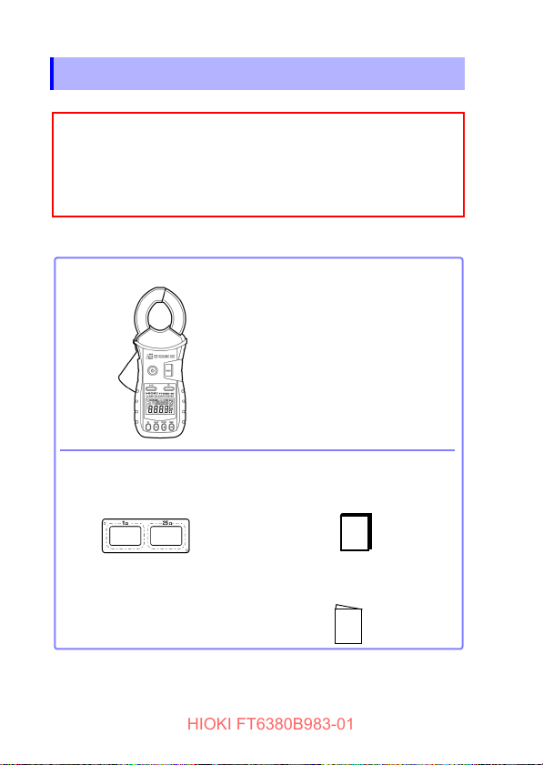
Verifying Package Contents
When you receive the instrument, inspect it carefully to ensure
that no damage occurred during shipping. In particular, check
the accessories, panel switches, and connectors. If damage is
evident, or if it fails to operate according to the specifications,
contact your authorized Hioki distributor or reseller.
□ FT6380-50 Clamp on Earth Tester
□ Instruction Manual (this manual)
□ Carrying case
□ Resistance check loop
(1 Ω ±2%, 25 Ω ±1%)
□ LR6 Alkaline battery ×2
□ Strap
□ Operating Precautions
(0990A907)
HIOKI FT6380B983-01
2
Verifying Package Contents
Confirm that these contents are provided.
Accessories
Use the original packing materials when transporting the instrument, if
possible.
For other transportation notes, refer to the “Transporting” (p.66).
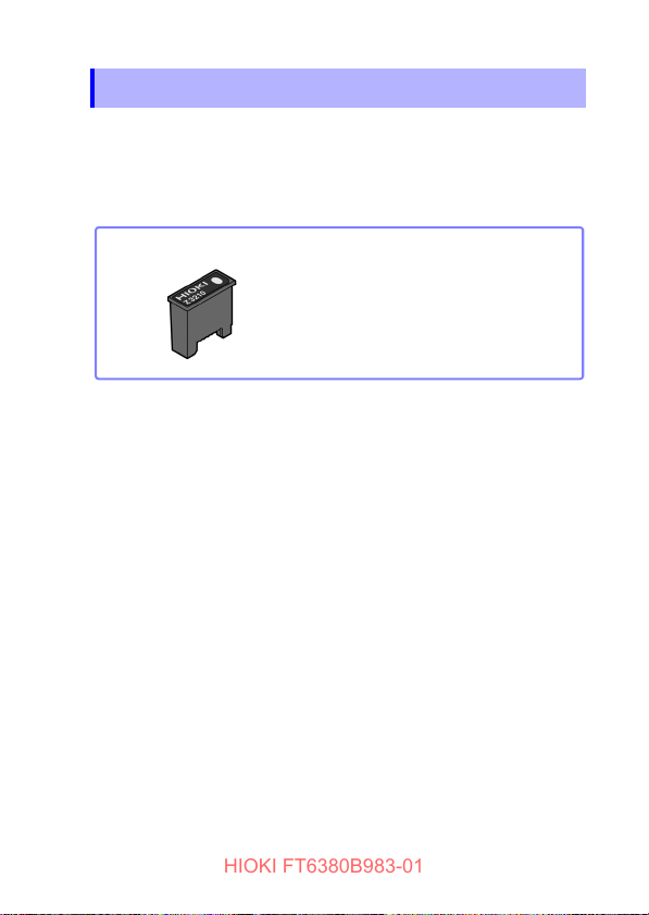
Option (sold separately)
□ Z3210 Wireless Adapter
HIOKI FT6380B983-01
Option (sold separately)
The option listed below is available for the instrument. To order
an option, please contact your authorized Hioki distributor or
reseller. Options are subject to change. Check Hioki’s website
for the latest information.
3
Safety Information
HIOKI FT6380B983-01
4
Safety Information
This instrument is designed to conform to IEC 61010 Safety
Standards and has been thoroughly tested for safety prior to
shipment. However, using the instrument in a way not described
in this manual may negate the provided safety features. Carefully read the following safety notes before using the instrument.
Mishandling instrument could result in bodily injury or
even death, as well as damage to the instrument.
Familiarize yourself with the instructions and precautions
in this manual before use.
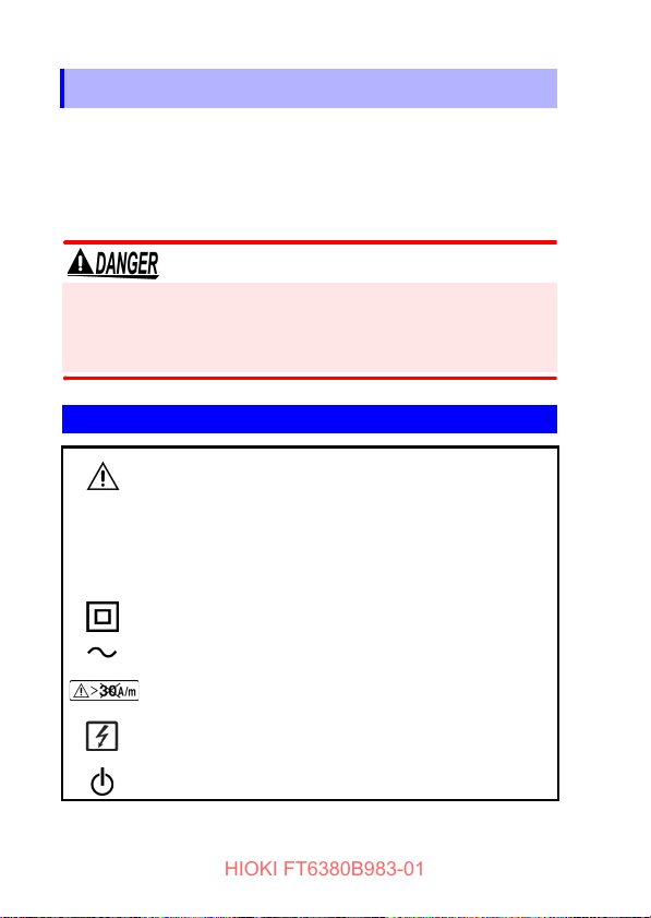
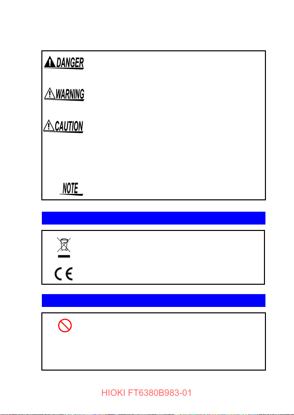
Symbols on equipment
Indicates the need for caution or the presence of a
hazard. For more information about locations
where this symbol appears on instrument components, see “Operating Precautions” (p.8), warning
messages listed at the beginning of operating
instructions, and the document entitled “Operating
Precautions” that comes with the instrument.
Indicates a double-insulated device.
Indicates AC (Alternating Current).
Indicates that using the instrument in an external
magnetic field of exceeding 30 A/m is prohibited.
Indicates that the instrument may be connected to
or disconnected from a live circuit.
Indicates whether the power is on or off.
Safety Information
HIOKI FT6380B983-01
The following symbols in this manual indicate the relative importance of cautions and warnings.
Indicates an imminently hazardous situation
that, if not avoided, will result in death of or
serious injury to the operator.
Indicates a potentially hazardous situation that,
if not avoided, could result in death of or serious injury to the operator.
Indicates a potentially hazardous situation that,
if not avoided, could result in minor or moderate injury to the operator.
IMPORTANT
Indicates information or content that is particularly important from the standpoint of operating
or maintaining the instrument.
Indicates the possibility of equipment damage.
Symbols for Various Standards
Indicates the Waste Electrical and Electronic
Equipment Directive (WEEE Directive) in EU
member states.
Indicates that the instrument complies with standards imposed by EU directives.
Other Symbols
5
(p. #)
[ ] Information displayed on the screen is enclosed
Indicates a prohibited action.
Indicates the location of reference information.
in brackets.

Safety Information
Over-range display
Open display
Resistance measurement: When the reading exceeds 1,600 Ω
Current measurement: When the reading
exceeds 60.0 A.
This screen is displayed when the clamp
sensor is not completely closed during use
of the resistance measurement function.
HIOKI FT6380B983-01
6
Fn
(bold
characters)
Bold text indicates alphanumeric characters
shown on operation keys.
The screen of this instrument displays characters in the following manner.
Screen displays that differ from the above notation:
Symbols for Various Standards
Hioki expresses accuracy as error limit values specified in terms
of percentages of reading.
Reading
(displayed
value)
Refers to the displayed value of the measuring instrument. The limit values of reading
errors are expressed in percent of reading
(% of reading, % rdg).

Safety Information
HIOKI FT6380B983-01
Measurement categories
This instrument complies with CAT IV safety requirements.
To ensure safe operation of measurement instruments IEC
61010 establishes safety standards for various electrical environments, categorized as CAT II to CAT IV, and called measurement categories.
Primary electrical circuits in equipment connected
CAT II
CAT III
CAT IV
Using a measurement instrument in an environment designated
with a higher-numbered category than that for which the instrument is rated could result in a severe accident, and must be
carefully avoided.
Use of a measurement instrument that is not CAT-rated in CAT II
to CAT IV measurement applications could result in a severe
accident, and must be carefully avoided.
to an AC electrical outlet by a power cord (portable
tools, household appliances, etc.)
CAT II covers directly measuring electrical outlet
receptacles.
Primary electrical circuits of heavy equipment
(fixed installations) connected directly to the distribution panel, and feeders from the distribution
panel to outlets.
The circuit from the service drop to the service
entrance, and to the power meter and primary
overcurrent protection device (distribution panel).
7
Operating Precautions
HIOKI FT6380B983-01
8
Operating Precautions
Follow these precautions to ensure safe operation and to obtain
the full benefits of the various functions.
Use of the instrument should confirm not only to its specifications, but also to the specifications of all accessories, options,
batteries, and other equipment in use.
Preliminary Checks
Before using the instrument for the first time, verify that it operates normally to ensure that no damage occurred during storage
or shipping. If you find any damage, contact your authorized
Hioki distributor or reseller.
Instrument Installation
Operating temperature: -10°C to 50°C (14°F to 122°F)
(Be sure to use batteries that are suited for use under the environmental conditions in which you are using the instrument.)
Operating humidity: 80% RH or less (non condensating)
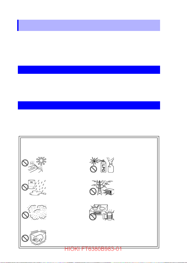
Avoid the following locations that could cause an accident or
damage to the instrument.
Exposed to direct
sunlight
Exposed to high temperature
Exposed to water, oil,
other chemicals, or
solvents Exposed to
high humidity or condensation
Exposed to high levels of particulate dust
In the presence of corrosive or explosive
gases
Exposed to strong
electromagnetic fields
Near electromagnetic
radiators
Near electromagnetic
radiators (e.g., highfrequency induction
heating systems and
IH cooking utensils)
Subject to vibration

Operating Precautions
HIOKI FT6380B983-01
Handling the Instrument
• To avoid short circuits and potentially life-threatening
hazards, never attach the clamp to a circuit that operates
at more than 600 V AC, or over bare conductors.
• The maximum rated voltage between input terminals and
ground is 600 V AC. Measuring a voltage in excess of this
rating relative to ground could damage the instrument
and result in bodily injury.
• To avoid electric shock, do not remove the instrument's
case. The internal components of the instrument carry
high voltages and may become very hot during operation.
• When the clamp sensor is opened, do not allow the metal
part of the clamp sensor to touch any exposed metal, or
to short between two lines, and do not use over bare conductors.
To avoid electric shock when measuring live lines, wear
appropriate protective gear, such as insulated rubber
gloves, boots and a safety helmet.
9

Operating Precautions
Frequency [Hz]
Current [A]
HIOKI FT6380B983-01
10
• Do not input a current in excess of the maximum allowable
current. Doing so may damage the instrument or cause burns.
The maximum allowable current is 100 A AC continuous or
200 A AC within 2 minutes at 50 Hz/60 Hz. For more information about the frequency derating characteristics during continuous input, see the following diagram:
• To avoid damage to the instrument, protect it from physical
shock when transporting and handling. Be especially careful
to avoid physical shock from dropping.
• Be careful to avoid dropping the instrument or otherwise subjecting them to mechanical shock, which could damage the
mating surfaces of the core and adversely affect measurement.
• Although this instrument is dust resistant, it is not completely
dust- or waterproof. To prevent possible damage, avoid using
in dusty or wet environments.
• Do not slant the instrument or place it on top of an uneven surface. Dropping or knocking down the instrument can cause
injury or damage to the instrument.

Operating Precautions
HIOKI FT6380B983-01
• The protection rating for the enclosure of the instrument
(based on EN 60529) is IP40*. (The rating applies to the
clamp sensor when in the closed position.)
*: IP40
This indicates the degree of protection provided by the enclosure of the device against use in hazardous locations, entry of
solid foreign objects, and the ingress of water.
4: Protected against access to hazardous parts with wire mea-
suring 1.0 mm in diameter. The equipment inside the enclosure is protected against entry by solid foreign objects larger
than 1.0 mm in diameter.
0: The equipment inside the enclosure is not protected against
the harmful effects of water.
11

Operating Precautions
HIOKI FT6380B983-01
12

1.1 Product Overview
HIOKI FT6380B983-01
13
Overview Chapter 1
1.1 Product Overview
The FT6380-50 Clamp on Earth Tester makes grounding resistance measurements simply by being clamped to multiplegrounded ground wires. No auxiliary grounding rod is needed,
and there is no need to disconnect the ground wire from the
grounding rod.
The instrument also provides AC current measurement functionality and can measure currents ranging from leakage current on
the order of several mA to load currents of up to 60 A.
1.2 Features
HIOKI FT6380B983-01
14
1.2 Features
Compact, low-profile sensor
The compact, low-profile sensor can be used to clamp ground wires
with ease. The sensor design dramatically speeds the measurement
process by eliminating the need to pull out ground wires for clamping
or dig around the ground rod or wire.
Broad dynamic range
The instrument can easily measure grounding resistance of up to
0.02 Ω to 1,600 Ω with its auto-range function. Current measurement
ranges from small leakage current (maximum resolution 10 μA) to a
maximum of 60 A.
Noise check function (p.31)
The instrument automatically detects noise that may affect grounding resistance measurement and displays a [ ] mark.
True RMS display
True RMS calculation allows the instrument to accurately measure
distortion waveform currents.
Data hold function (p.37)
A large button that is easy to push lets you hold the measured value.
The button notifies the user of the hold status by lights up while the
value is being held.
Backlight function (p.37)
The instrument uses a white LED for excellent visibility so that display values can be read clearly, even in dark locations.
Auto-power-save (APS) function (p.54)
An auto-power-save function keeps batteries from running down
when you forget to turn off the instrument.

1.2 Features
HIOKI FT6380B983-01
15
Alarm function (p.39)
By setting a threshold, you can have the instrument make a PASS/
FAIL judgment and notify you of the result with a buzzer. You can set
threshold values as you prefer for each resistance and current and
choose between two judgment conditions: when the measured value
exceeds the threshold (High) and when it falls below the threshold
(Low).
Filter function (p.38)
Widespread use of switching power supplies and inverters has led to
cases where harmonic components are superimposed on leakage
current waveforms. The instrument’s filter function allows it to perform two types of measurement: leakage current as related to degradation of insulation, and leakage current including this harmonic
component.
Internal memory (p.42)
The instrument’s internal memory can record up to 2,000 measured
values.
Automatic measurement report function using your
mobile communication device (p.46)
The wireless communication function enables your mobile communication device to create measurement reports on-site easily.
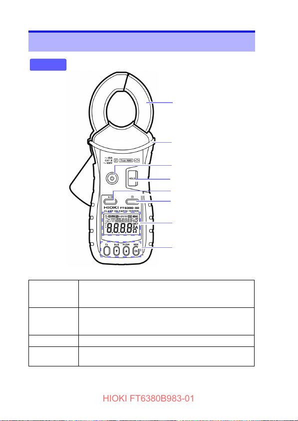
1.3 Names and Functions of Parts
Barrier
Front
Clamp sensor
Power key
HOLD key (p.37)
A/Ω key
Backlight key (p.37)
Display indicator (p.19)
Operation key (p.18)
HIOKI FT6380B983-01
16
1.3 Names and Functions of Parts
Power key • Used to turn the instrument on and off.
HOLD key • Holds the measured value display or cancels hold mode.
Backlight key • Turns the backlight on and off.
A/Ω key • Switches between resistance measurement mode and
• To temporarily cancel the auto-power-save function,
press the power key while holding down the HOLD key.
• To cancel auto-power-save mode, press the power key
while holding down the HOLD key.
current measurement mode.
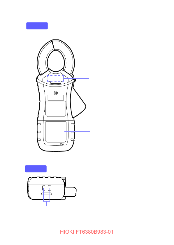
Battery cover (p.23)
Back
Strap hole
(p.22)
Bottom
Serial No.
The serial number consists of nine
digits. The first two digits indicate
the year of manufacture, while the
second two digits indicate the month
of manufacture.
Do not remove this sticker as the
number is important.
HIOKI FT6380B983-01
1.3 Names and Functions of Parts
17
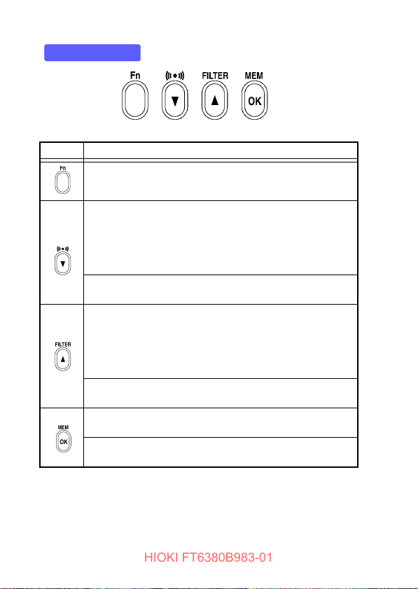
1.3 Names and Functions of Parts
Operation key
HIOKI FT6380B983-01
18
Key Description
Switches to function mode, which is used to configure settings. Pressing this key again will return to resistance measurement mode or current measurement mode. (p.51)
• Enables the alarm function. (p.39)
• When the alarm function is enabled, the instrument will
notify the user with the buzzer if a reading is greater than (or
less than) a preset threshold.
• Alarm function threshold settings can be configured in function mode. (p.41)
*In function mode, this key serves as the
used to select setting items and values.
• Pressing this key while using the current measurement function enables the low-pass filter to reject unneeded harmonic
components. (p.38)
• Pressing it while using the resistance measurement function
enables the moving average function, allowing more stable
measurement. (p.38)
*In function mode, this key serves as the
used to select setting items and values.
Saves measurement data to the instrument’s internal memory. (p.42)
*In function mode, this key serves as the
used to accept setting items and values.
▼ key, which is
▲ key, which is
OK key, which is

Display Indicators
HIOKI FT6380B983-01
1.3 Names and Functions of Parts
Lights up when data is being held. (p.37)
Lights up in function mode. (p.51)
Flashes in subfunction mode. (p.52)
Lights up when the alarm function is on. (p.39)
Lights up when the filter function is on. (p.38)
Lights up when the wireless communication function is on.
Flashes when data is being sent or received. (p.46)
Lights up when the auto-power-save function is on. (p.54)
Indicates the remaining battery power. (p.23)
Lights up in AC current measurement mode. (p.33)
Lights up in resistance measurement mode. (p.29)
Lights up in resistance measurement mode when a current
that could affect the measured value is detected. (p.31)
Lights up in resistance measurement mode when the measured ground loop has a high reactance component or capacitance component (
lights up due to a low measured resistance value, it is likely
that the displayed value indicates a shorted measurement
loop rather than normal grounding resistance. When the
] mark lights up, the loop may have a break in it. In this
[
case, the mark indicates that the wires have been coupled by
capacitance.) (p.32)
±45° or greater). (When the [ ] mark
19
1.3 Names and Functions of Parts
HIOKI FT6380B983-01
20
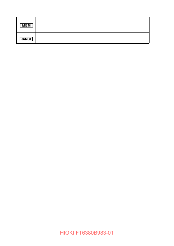
Lights up during internal memory operations. (p.42)
The number of measurement data points stored in memory is
shown to the right.
Lights up when the range display function is on.
The measurement range is shown to the right.
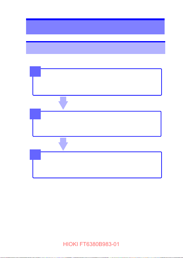
Measurement Chapter 2
Measurement
Resistance Measurement (p.29)
Current Measurement (p.33)
End of measurement
Remove the instrument from the measurement target.
Turn off the instrument.
Measurement Preparations
Pre-Operation Inspection (p.26)
Using the included resistance check loop to inspect the
instrument (p.27)
3
2
1
HIOKI FT6380B983-01
2.1 Measurement process
2.1 Measurement process
21
2.2 Preparing for Measurement
HIOKI FT6380B983-01
22
2.2 Preparing for Measurement
After purchasing the instrument
Complete the following steps before using the instrument to
make measurements.
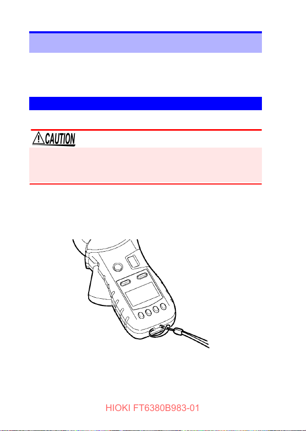
Attaching the Strap
Attach both ends of the Strap securely to the instrument.
If insecurely attached, the instrument may fall and be damaged
when carrying
Thread the strap through the strap hole as shown in the following diagram:
2.2 Preparing for Measurement
HIOKI FT6380B983-01
23
Installing (or Replacing) the Battery and Wireless
Adapter
Before using the instrument for the first time, install two LR6
Alkaline batteries.(p.25) Verify that there is sufficient battery
power remaining before measurement. If there is insufficient battery power remaining, replace the batteries.
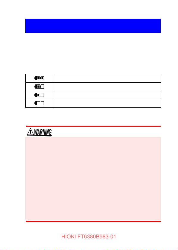
Battery Status Indicator
This indicator is displayed at the top right corner.?
When new alkaline batteries have been installed
When 2/3 of the battery power remains
When 1/3 of the battery power remains
No battery power remains. Replace with new batteries.
When the Z3210 Wireless Adapter (option) is installed, the wireless communication function can be used.(p.46)
• To avoid electric shock, disconnect the clamp from the
measuring object before removing the battery cover.
• After replacing the batteries or after installing or removing the Z3210, install the battery cover and tighten the
screws before use.
• Battery may explode if mistreated. Do not short- circuit,
recharge, disassemble or dispose of in fire.
• Handle and dispose of batteries in accordance with local
regulations
• To prevent instrument damage or an electric shock, use
only the screws that are originally installed for securing
the battery cover in place. If you have lost a screw or find
that a screw is damaged, please contact your authorized
Hioki distributor or reseller.

2.2 Preparing for Measurement
HIOKI FT6380B983-01
24
• Do not mix old and new batteries, or different types of batteries. Also, be careful to observe battery polarity during installation. Otherwise, poor performance or damage from battery
leakage could result.
• To avoid corrosion from battery leakage, remove the batteries
from the instrument if it is to be stored for a long time.
• After touching any metallic part, such as a doorknob, to eliminate static electricity from your body, connect/disconnect the
Z3210. Failure to do so could cause static electricity to damage the Z3210.
•
The [ ] indicator lights when battery voltage becomes
low. Replace the batteries as soon as possible.
• Before replacing the batteries, make sure to turn off
the instrument.
• After use, always turn off the instrument.
• If the battery is completely exhausted, the display will
show [
bAtt → P.oFF], and the instrument will automati-
cally turn off.
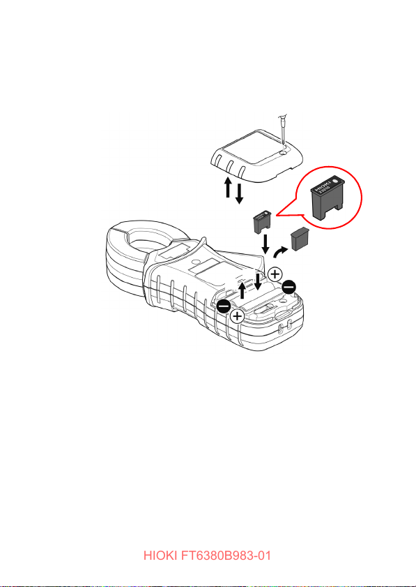
Installing (replacing) the batteries and wireless adapter
2
3
5
6
7
4
Rear
Prepare the following.
• LR6 Alkaline battery ×2
• Z3210 Wireless Adapter (option)
• Phillips screwdriver
HIOKI FT6380B983-01
Start the following procedure after reading the safety precautions.(p.23)
Disconnect the instrument from the measuring object
1.
and turn off the power.
Loosen the screws and remove the battery cover.
2.
Remove the old batteries (when replacing the batteries).
3.
Install new batteries, taking care to orient them properly.
4.
When installing the wireless adapter, remove the pro-
5.
tective cap.
Insert the wireless adapter all the way inside while
6.
carefully checking its orientation.
Install the battery cover and tighten the screws.
7.
2.2 Preparing for Measurement
25
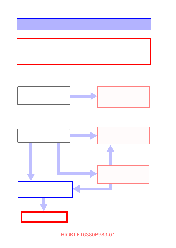
2.3 Pre-Operation Inspection
Before using the instrument for the first time, verify that it operates normally to ensure that no damage occurred during storage or shipping. If you find any damage, contact your
authorized Hioki distributor or reseller.
Does the screen turn on when
the instrument is turned on?
The batteries may be dead.
Replace the batteries and try
again.
The instrument may be malfunctioning. Have the instrument repaired.
• Is the instrument damaged?
• Is the clamp sensor cracked
or otherwise damaged?
No
End of inspection
Yes
An error is
displayed.
• The screen is not on.
• The screen shows an
error.
Do not use the instrument if it
is damaged as doing so may
result in electric shock. Have
the instrument repaired.
Yes
1. Inspecting the instrument
2. Inspecting the instrument after turning it on
The screen is on.
Using the included resistance
check loop to inspect the instrument (p.27)
HIOKI FT6380B983-01
26
2.3 Pre-Operation Inspection
 Loading...