

Page 1

Instruction Manual
Manual de Instrucciones
FT6380
FT6381
CLAMP ON EARTH TESTER
MEDIDOR DE RESISTENCIA
DE TIERRA TIPO GANCHO
March 2014 Revised edition 1
FT6380A983-01 (A981-03) 14-03H
Page 2

Page 3

i
Contents
Introduction .......................................................................... 1
Verifying Package Contents ................................................2
Safety Information ................................................................3
Operating Precaution s ................ ............ .............................7
Chapter 1 Overview 11
1.1 Product Overview ..............................................11
1.2 Features ............................................................ 12
1.3 Names and Functions of Parts .......................... 14
Operation key ....................................................16
Display Indicators............................... ............ ... 17
Chapter 2 Measurement 19
2.1 Measurement proces s ............................... ........19
2.2 Preparing for Measurement ..............................20
Attaching the Strap............................................ 20
Installing (or Replacing) the Battery.................. 21
2.3 Pre-Operation Ins p e ct i o n .......................... ........23
Using the included resistance check loop to
inspect the instrument ....................................... 24
2.4 Measurement Procedure ...................................25
Resistance Measurement .................................26
Current Measurement ........ ............. ............ ......29
2.5 Convenient function ..........................................33
Data hold function (Holding the measured value) 33
Backlight function
(Making measurements in a dark location)......... 33
Filter function (Rejecting noise) .........................34
Alarm function (Judging measured values and
sounding an alarm)............................................. 35
Memory function (Saving measurem ent data) ... 38
Page 4

ii
Making meas urements with an Android™
handset (FT6381 only)....................................... 42
Enabling the Bluetooth® function on the FT6381 43
Pairing the instrument with an Android™
handset (first use only)........................................ 44
Installing the FT6381 Communication Software
on the Android™ handset................................... 45
Registering the instrument you wish to connect
with the FT6381 Communication Software......... 46
Switching the FT6381 to connect with the
Android™ handset.............................................. 48
Using the FT6381 Communication Software
(second and subsequent use)............................. 48
2.6 Advanced Setti ngs a nd Fun ctions .....................51
Enabling/disabling the measuremen t range
display function ................................................... 52
Enabling/disabling the auto-power-saving (APS)
function.................... ............. ............ ............. ..... 53
Reverting the instrument to factory settings
(system reset)......................... ............ ............. ... 54
Chapter 3 Specifications 55
3.1 Measurement Specif ic at io n s ................... ..........55
3.2 General Specifications .......................................59
Chapter 4 Maintenance and Service 63
4.1 Cleaning ............................................................63
4.2 Troubleshooting .................................................6 4
Inspection and Repair........................................ 64
Before returning for repair .................................64
4.3 Error Display ......................................................65
Page 5

Introduction
1
Introduction
Thank you for purchasing the HIOKI Model FT6380, FT6381
CLAMP ON EARTH TESTER. To obtain maximum performance
from the instrument, please read this manual first, and keep it
handy for future reference.
Registered Trademarks
®
• Bluetooth
(USA).
• Android
tooth
• Adobe and Reader are either registered trademarks or trademarks of Adobe Systems Incorporated in the United States and
/or other countries.
is a registered trademark of Bluetooth SIG, Inc.
TM
Google PlayTM is a registered trademark of Blue-
®
Google, Inc.
Page 6
Verifying Package Contents
2
When you receive the instrument, inspect it carefully to
ensure that no damage occurred during shipping. In particular, check the accessories, panel switches, and connectors. If
damage is evident, or if it fails to operate according to the
specifications, contact your dealer or Hioki representative.
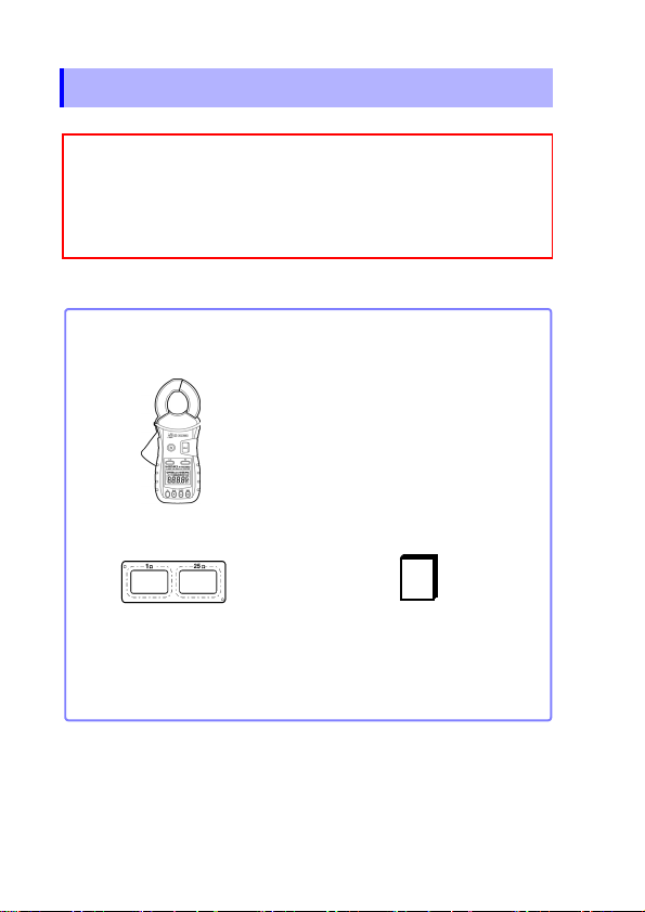
Confirm that these contents are provided.
□
FT6380 or FT6381 Clamp On Earth Tester (1)
□ Instruction Manual (1)
□ Carrying Case (1)
□ Resistance Check Loop (1)
□ LR6 alkaline batteri es (2)
□ Strap (1)
Verifying Package Contents
Package Contents
Use the original packin g materials when transporting the in strument, if
possible.
For other transportation notes, refer to the "Transporting (p.64)".
Page 7
Safety Information
3
Safety Information
This instrument is designed to comply with IEC 61010
Safety Standards, and has been thoroughly tested for
safety prior to shipment. However, mishandling during use
could result in injury or death, as well as damage to the
instrument. However, using the instrument in a way not
described in this manual may negate the provided safet y
features. Be certain that you understand the instructions
and precautions in the manual before use. We disclaim any
responsibility for accidents or injuri es not resul ting directly
from instrument defects.
This manual contains information and warnings essential for
safe operation of the instrument and for maintaining it in safe
operating condition. Before using it, be sure to carefully read the
following safety precautions.
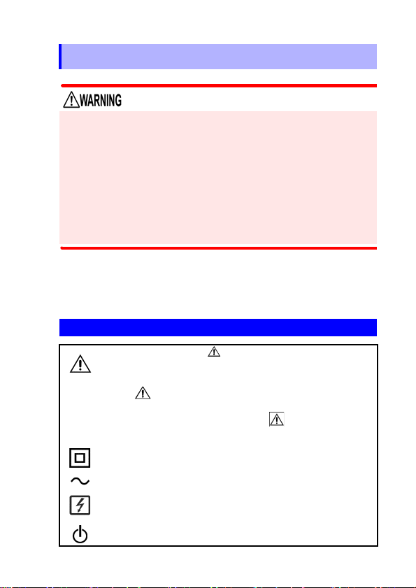
Safety Symbols
In the manual, the symbol indicates particularly
important information that the user should read
before using the instrument.
The symbol printed on the instrument indicates
that the user should refer to a corresponding topic in
the manual (marked with the symbol) before
using the relevant function.
Indicates a double-insulated device.
Indicates AC (Alternating Current).
Indicates that the instrument may be connected to or
disconnected from a live circuit.
Indicates the power on/off button.
Page 8
Safety Information
4
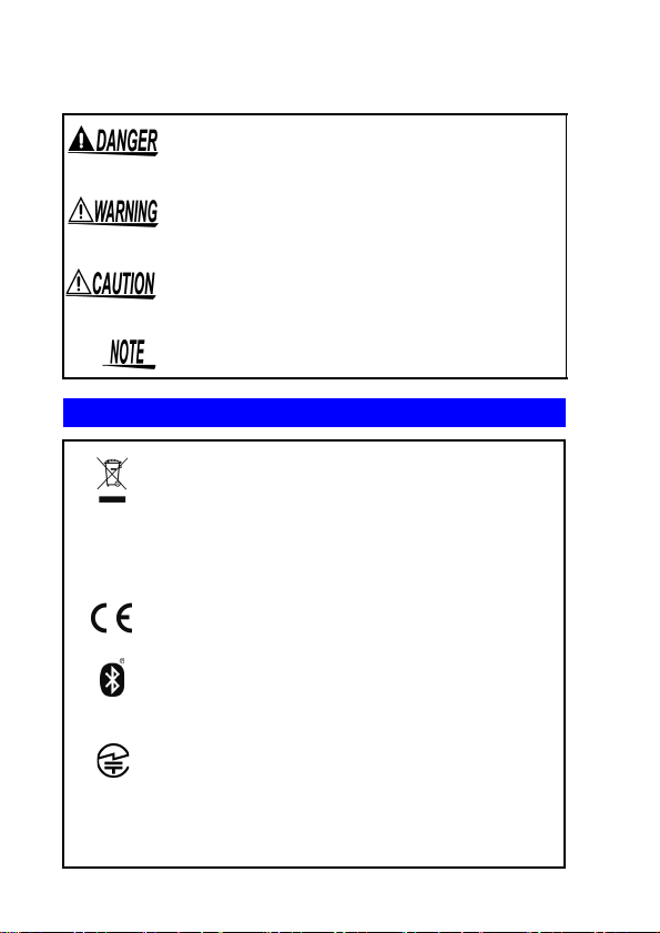
The following symbols in this manual indicate the relative importance of cautions and warnings.
Indicates that incorrect operation presents an
extreme hazard that could result in serious
injury or death to the user.
Indicates that incorrect operation presents a
significant hazard that could result in serious
injury or death to the user.
Indicates that incorrect operation presents a
possibility of injury to the user or damage to the
instrument.
Indicates advisory items related to performance or correct operation of the instrument.
Symbols for Various Standards
WEEE marking:
This symbol indicates that the electrical and
electronic appliance is put on the EU market
after August 13, 2005, and producers of the
Member States are required to display it on the
appliance under Article 11.2 of Directive 2002/
96/EC (WEEE).
This symbol indicates that the product conforms
to regulations set out by the EC Directive.
®
FCC ID
Indicates that the product incorporates Bluetooth
wireless technology. Bluetooth® is a registered
trademark of Bluetooth SIG, Inc., and is used
under license by HIOKI E.E. CORPORATION.
Indicates that the product conforms to the
domestic Japan ese techni cal standa rds set fo rth
by the Radio Act (type certification).
Indicates the ID number of the wireless module
certified by the U.S. Federal Communications
Commission (FCC).
Page 9
Safety Information
5
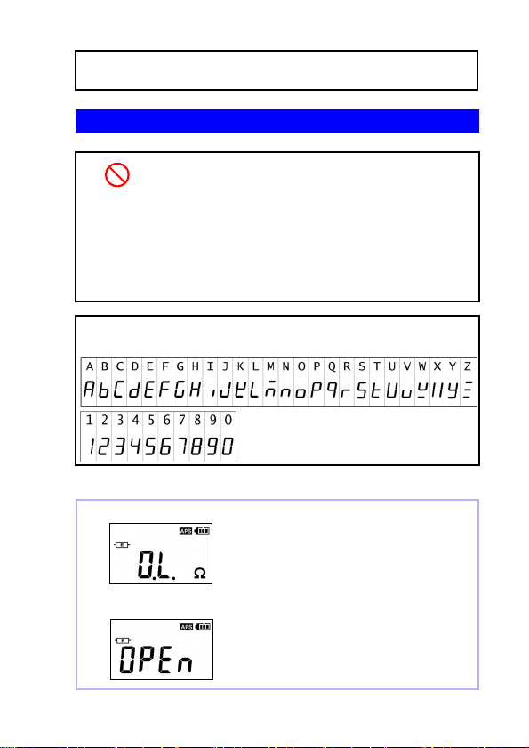
Over-range display
Open display
Resistance measuremen t: Wh en the reading exceeds 1,600 Ω
Current measurem ent: When the reading
exceeds 60.0 A.
This screen is displayed when the clamp
sensor is not complete l y clo sed during use
of the resistance measurement function.
IC
Other Symbols
(p. #)
[ ] Information displayed on the screen is enclosed
Fn
(bold
characters)
The screen of this instrument displays characters in the following manner.
Screen displays that differ from the above notation:
Indicates the number of the wireless module
certified by Industry Canada.
Indicates a prohibited action.
Indicates the location of reference information.
in brackets.
Bold text indicates alphanumeric characters
shown on operation keys.
Page 10
Safety Information
6
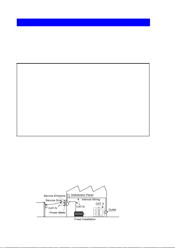
Measurement categories
This instrument complies with CAT IV safety requirements.
To ensure safe operation of measurement instruments IEC
61010 establishes safety standards for various electrical environments, categorized as CAT II to CAT IV, and called measurement categories.
Primary electrical circuits in equipment connected
CAT II
CAT III
CAT IV
Using a measurement instrument in an environment designated
with a higher-numbered category than that for which the instrument is rated could result in a severe ac cident, and must be
carefully avoided.
Use of a measurement instrument that is not CAT-rated in CAT II
to CAT IV measurement applications could result in a severe
accident, and must be carefully avoided.
to an AC electrical outlet by a power cord (portable
tools, household appliances, etc.)
CAT II covers directly measuring electrical outlet
receptacles.
Primary electrical circuits of heavy equipment
(fixed installations) connected directly to the distribution panel, and feeders from the distribution
panel to outlets.
The circuit from the service drop to the service
entrance, and to the power meter and primary
overcurrent protection device (distribution panel).
Page 11
Operating Precautions
7
Operating Precautions
Follow these precautions to ensure safe operation and to obtain
the full benefits of the various functions.
Preliminary Checks
Before using the instrument for the first time, verify that it operates normally to ensure that no damage occurred during storage
or shipping. If you find any damage, contact your dealer or Hioki
representative.
Instrument Installation
Operating temperature:-10 to 50°C (14 to 122°F)
(Be sure to use batteries that are suited for use under the environmental conditions in which you are using the instrument.)
Operating humidity: 80%RH or less (non condensating),
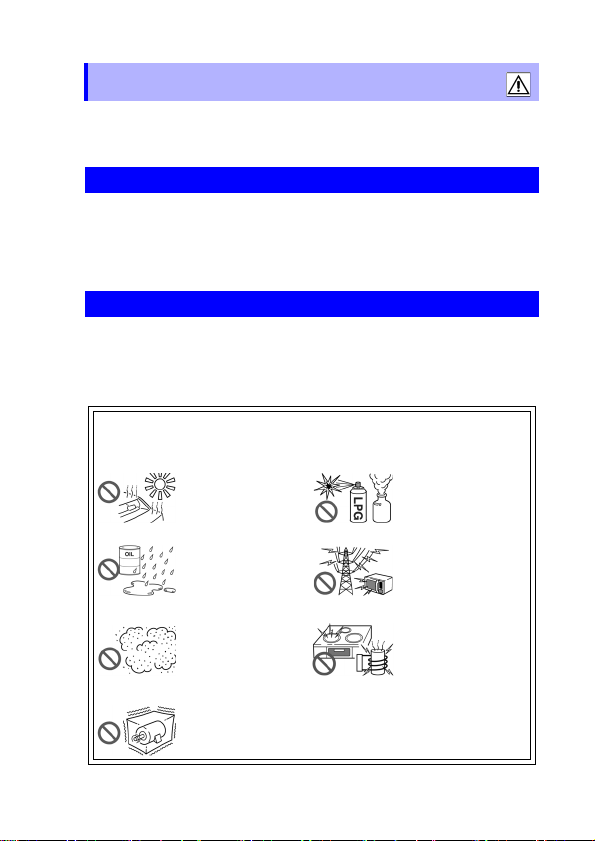
Avoid the following locations that could cause an accident or
damage to the instrument.
Exposed to direct
sunlight
Exposed to high temperature
Exposed to water, oil,
other chemicals, or
solvents Exposed to
high humidity or condensation
Exposed to high levels of particulate dust
In the presence of corrosive or explosive
gases
Exposed to strong
electromagnetic fields
Near electromagnetic
radiators
Near electromagnetic
radiators (e.g., highfrequency induction
heating systems and
IH cooking utensils)
Subject to vibration
Page 12
Operating Precautions
8
Handling the Instrument
• To avoid short circuits and potentially life-threatening
hazards, never attach the clamp to a circuit that operates
at more than 600 V, or over bare conductors.
• The maximum rated voltage between input terminals and
ground is 600 VAC. Measuring a voltage in excess of this
rating relative to ground could damage the instrument
and result in bodily injury.
• To avoid electric shock, do not remove the instrument's
case. The internal components of the instrument carry
high voltages and may become very hot during operation.
• When the clamp sensor is opened, do not allow the metal
part of the clamp to touch any exposed metal, or to short
between two lines, and do not use over bare conductors.
To avoid electric shock when measuring live lines, wear
appropriate protective gear, such as insulated rubber
gloves, boots and a safety helmet.
Page 13
Operating Precautions
9
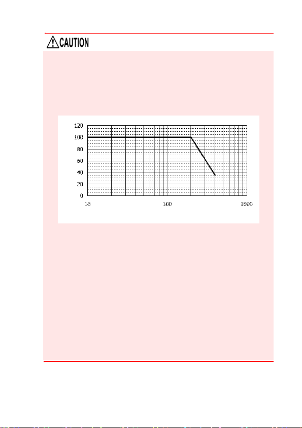
Frequency [Hz]
Current [A]
• Do not input a cur rent in excess of the maximum allowable
current. Doing so may damage the instrument or cause burns.
The maximum allowable current is 100 AAC continuous or
200 A AC within two minutes at 50/60 Hz. For more information about the frequency derating characteristics during continuous input, see the following diagram:
• To avoid damage to the instrument, protect it from physical
shock when transporting and handling. Be especially careful
to avoid physical shock from dropping.
• Be careful to avoid dropping the instrument or otherwise subjecting them to mechanical shock, which could damage the
mating surfaces of the core and adversely affect measurement.
• Although this instrument is dust resistant, it is not co mpletely
dust- or waterproof. To prevent possible damage, avoid using
in dusty or wet environments.
• Do not slant the device or place it on top of an uneven surface.
Dropping or knocking down the device can cause injury or
damage to the device.
Page 14
Operating Precautions
10
• The protection rating for the enclosure of this device (based
on EN60529) is *IP40. (The rating applies to the clamp sensor
when in the closed position.)
*IP40
This indicates the degree of protection provided by the enclosure of the device against use in hazardous locations, entry of
solid foreign objects, and the ingress of water.
4: Protected against access to hazardous parts with wire mea-
suring 1.0 mm in diameter. The equipment inside the enclosure is protected against entry by solid foreign objects larger
than 1.0 mm in diameter.
0: The equipment inside the enclosure is not protected against
the harmful effects of water.
Page 15

1.1 Product Overview
11
Overview Chapter 1
1.1 Product Overview
The FT6380 and FT6381 Clamp On Earth Tester make grounding resistance measurements simply by being clamped to multiple-grounded ground wires. No auxiliary grounding rod is
needed, and there is no need to disconnect the ground wire from
the grounding rod.
The instruments also provide AC current measurement functionality and can measure currents ranging from leakage current on
the order of several mA to load currents of up to 60 A.
The FT6381 emits radio radiation. Because use of devices that
emit radio radiation requires approval in the co untry of use, be
careful that use of the instrument in a country or region other
than those listed on the attached cautionary leaflet, "Precautions
Concerning Use of Equipment That Emits Radio Waves" or the
HIOKI products website may be subject to penalty as a violation
of law.
Page 16
1.2 Features
12
1.2 Features
Compact, low-profile sensor
The compact, low-profile sensor can be used to clamp ground wires
with ease. The sensor design dramatically speeds the measurement
process by eliminating the need to pull out ground wires for clamping
or dig around the ground rod or wire.
Broad dynamic range
The instrument can easily measure grou nding resistance of u p to
0.02 to 1,600 Ω with its auto -range fu nction. Cur rent meas urement
ranges from small leakage current (maximum resolution 10 μA) to a
maximum of 60 A.
Noise check function (p.28)
The instrument automat ically detects no ise that may affe ct grounding resi stance measurement and display s a mark.
True RMS display
True RMS calculation allows the instrument to accurately measure
distortion waveform currents.
Data hold function (p.33)
A large button that is easy to push lets you hold the measured value.
The button notifies the us er of the hold status by fl ashing w hile the
value is being held.
Backlight function (p.33)
The instrument uses a white LED for excellent visibility so th at display values can be read clearly, even in dark locations.
Auto-power-save (APS) function (p.53)
An auto-power-save function keeps batteries from running down
when you forget to turn off the instrument.
Page 17

1.2 Features
13
Alarm function (p.35)
By setting a threshold, yo u can ha ve the ins trumen t make a PASS/
FAIL judgment and notify you of the result with a buzzer. You can set
separate thresholds for resista nce and current measurements and
select judgment criteria (whether to generate a FAIL result when the
reading is greater than or less than the threshold).
Filter function (p.34)
Widespread use of switching power supplies and inverters has led to
cases where harm onic components are superimp osed on le akage
current waveforms. The instrument’s filter function allows it to perform two types of mea sureme nt: leaka ge cur rent a s rel ated to degradation of insulation , and leakage current i ncluding this harmonic
component.
Internal memory (p.38)
The instrument’s internal memory can record up to 2,000 measured
values.
Automatic measurement report function with
Android
The FT6381 featur es Bluetooth® wireless technology and can be
connected to a smartphone running the Android operating system to
easily create measurement reports in the field. (FT6381 ava ilability
is limited to certa in countries. For more informa tion, contact your
dealer or Hioki representative.)
™ connectivity (*FT6381 only) (p.42)
Page 18
1.3 Names and Functions of Parts
14
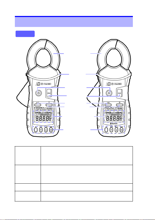
Barrier
Front
Clamp sensor
FT6380 FT6381
POWER key
HOLD key
(p.33)
A/Ω key
Backlight key
(p.33)
Display Indicator
(p.17)
Operation key
(p.16)
1.3 Names and Functions of Parts
POWER key
HOLD key
Backlight key
A/Ω key
• Used to turn the instrument on and off.
• To temporarily cancel the auto-power-save function,
press the POWER key while holding down the HOLD
key.
• Holds the measured value display or cancels hold
mode.
• To cancel auto-power-save mode, press the POWER
key while holding down the HOLD key.
• Turns the backlight on and off.
• Switches between resistan ce measure ment mode and
current measurement mode.
Page 19
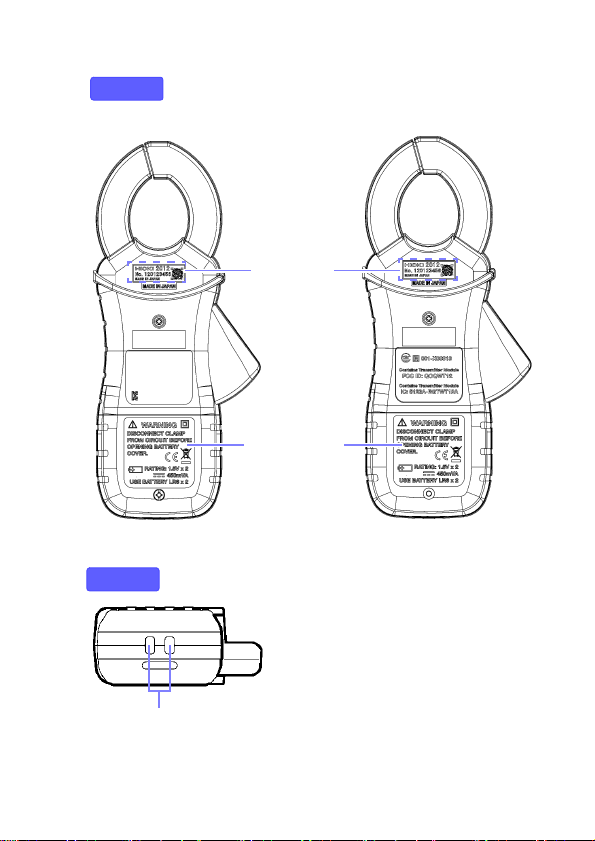
15
Battery cover
(p.21)
Back
Strap hole
(p.20)
Bottom
FT6380
FT6381
Serial No.
1.3 Names and Functions of Parts
Page 20
1.3 Names and Functions of Parts
16
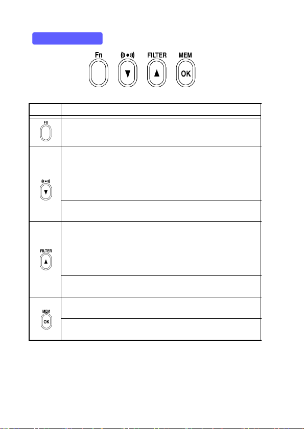
Operation key
Key Description
Switches to function mode , which is used to configure settings. Pressing this key again will return to resistance measurement mode or current measurement mode.
• Enables the alarm function. (p.35)
• When the alarm function is enabled, the instrument will
notify the user with the buzzer if a reading is greater than (or
less than) a preset threshold.
• Alarm function threshold se ttings can b e configur ed in function mode. (p.37)
*In function mode, this key serves as the
used to select setting items and values.
• Pressing this key while using the current measurement function enables the l ow-pass fi lte r to r ej ect un nee de d h arm on ic
components. (p.34)
• Pressing it while using the resistance measurement function
enables the moving averag e function, allowin g more stable
measurement. (p.34)
*In function mode, this key serves as the
used to select setting items and values.
Saves measurement data to the instrument’s internal memory. (p.38)
*In function mode, th is key serves as the
used to acc ept setting items an d values.
▼ key, which is
▲ key, which is
OK key, which is
Page 21
17
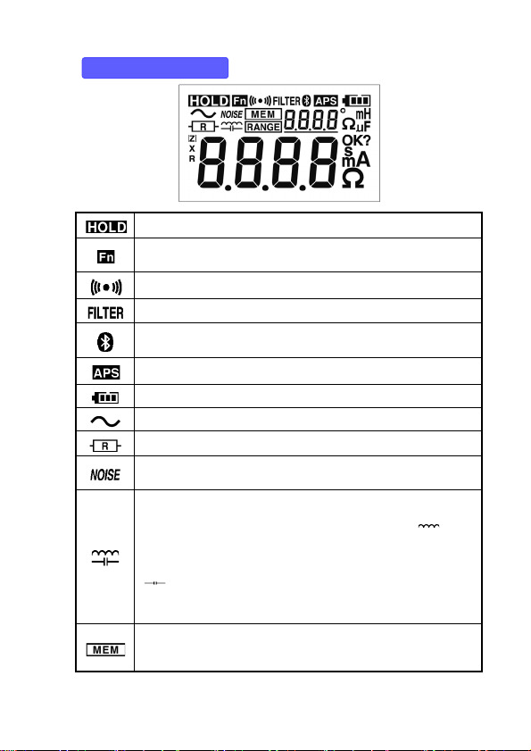
Display Indicators
1.3 Names and Functions of Parts
Lights up when data is being held. (p.33)
Lights up in function mode. (p.50)
Flashes in subfunction mode. (p.51)
Lights up when the alarm function is on. (p.35)
Lights up when the filter function is on. (p.34)
Lights up when the Blue tooth
data is being sent or received. (model FT6381 only) (p.42)
Lights up when the auto-power-save function is on. (p.53)
Indicates the remaining battery power. (p.22)
Lights up in AC current measurement mode. (p.29)
Lights up in resistance measurement mode. (p.26)
Lights up in resistance measuremen t mode when a current
that could affect the measured value is detected. (p.28)
Lights up in resistance measuremen t mode when the mea-
sured ground loop has a high reactance component or capacitance component (
lights up due to a low mea sured resistance value, it is likely
that the displayed value indicates a shorted measurement
loop rather than normal grounding resistance. When the
] mark lights up, t he loop m ay have a break in it. In t his
[
case, the mark indicates th at the wire s ha ve b ee n co up led b y
capacitance.) (p.28)
Lights up during internal memory oper ati o ns. (p.3 8)
The number of measurem ent data poin ts stored in memo ry is
shown to the right.
±45° or greater). (When the [ ] mark
®
function is on. Flashes whe n
Page 22

1.3 Names and Functions of Parts
18
Lights up when the range display function is on.
The measurement range is shown to the right.
Page 23
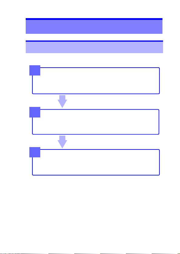
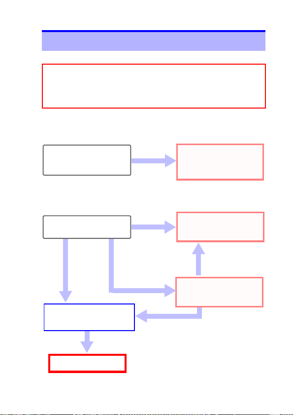
19
Measurement Chapter 2
Measurement
Resistance Measurement (p.26 )
Current Measurem ent (p.29 )
End of measurement
Remove the instrument from the measurement target.
Turn off the instrument.
Measurement Preparations
Pre-Operation Inspection (p.23)
Using the included resistance check loop to inspect the
instrument (p.24)
3
2
1
2.1 Measurement process
2.1 Measurement process
Page 24
2.2 Preparing for Measurement
20
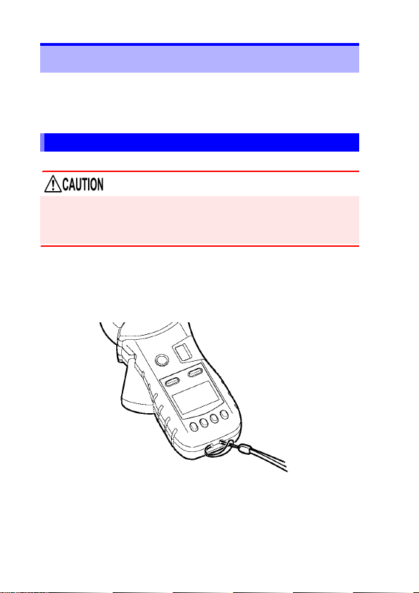
2.2 Preparing for Measurement
After purchasing the instrument
Complete the following steps before using the instrument to
make measurements.
Attaching the Strap
Attach both ends of the Strap securely to the instrument.
If insecurely attached, the instrument may fall and be damaged
when carrying
Thread the strap through the strap hole as shown in the f ollowing diagram:
Page 25

2.2 Preparing for Measuremen t
21
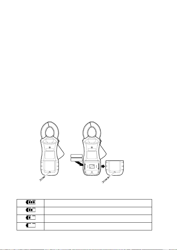
Installing (or Replacing) the Battery
Before using the instrument for the first time, install two AA-size
alkaline batteries (LR6). Verify that there is sufficient battery
power remaining before measurement. If there is insufficient battery power remaining, replace the batteries.
• To avoid electric shock when replacing the batteries, first
disconnect the clamp from the object to be measured.
• After replacing the batteries, replace the cover and
screws before using the instrument.
• Battery may explode if mistreated. Do not short- circuit,
recharge, disassemble or dispose of in fire.
• Handle and dispose of batteries in accordance with local
regulations
• Do not mix old and new batteries, or different types of bat teries. Also, be careful to observe bat tery polarity dur ing installation. Otherwise, poor performance or damage from battery
leakage could result.
• To avoid corrosion from battery leakage, remove the batteries
from the instrument if it is to be stored for a long time.
•
The indicator lights when battery voltage becomes
low. Replace the batteries as soon as possible.
• Before replacing the batteries, make sure that the
Slide Switch is OFF.
• After use, always turn OFF the power.
• If the battery is completely exhaus ted, the display will
show [BAttLo], and the instrument will automatically
turn off.
Page 26
2.2 Preparing for Measurement
22
2
3
4
Required Items:
• Phillips screwdriver
• LR6 alkaline battery (2)
Normal procedure
Verify that the instrument is off.
1.
Remove the fastening screws of the battery cover,
2.
using a Phillips screwdriver.
Remove the battery cover.
3.
Insert two new batteries (LR06 alkaline batteries),
4.
taking care to orient them properly.
Replace the battery cover and tighten the fastening
5.
screws.
Battery Status Indicator
This indicator is displayed at the top right corner.?
When new alkaline batteries have been installed
When 2/3 of the battery power remains
When 1/3 of the battery power remains
No battery power remains. Replace with new batteries.
Page 27
23
2.3 Pre-Operation Inspection
Before using the instrument for the first time, verify that it operates normally to ensure that no damage occurred during storage or shipping. If you find any damage, contact your dealer or
Hioki representative.
Does the screen turn on when
the instrument is turned on?
The batteries may be dead.
Replace the batteries and try
again.
The instrument may be malfunctioning. Have the instrument repaired.
• Is the instrument damaged?
• Is the clamp sensor cracked
or otherwise damaged?
No
End of inspection
Yes
An error is
displayed.
• The screen is not on.
• The screen shows an
error.
Do not use the instrument if it
is damaged as doing so may
result in electric shock. Have
the instrument repaired.
Yes
1. Inspecting the instrument
2. Inspecting the instrument after turning it on
The screen is on.
Using the included resistance
check loop to inspect the instrument (p.24)
2.3 Pre-Operation Inspection
Page 28

2.3 Pre-Operation Inspection
24
Resistance check loop
Using the included resistance check loop to
inspect the instrument
Before turning on the instrument, be sure to read Operating Precautions (p.7).
Inspecting the instrument with the resistance check loop
Verify that there is no foreign matter lodged between the tips of
the clamp sensor and that the sensor can be closed and opened
smoothly. If so, clamp the included resistance check loop and
verify that the instrument is operating properly. Verify that a
value within the allowable range is displayed for each loop.
Test resistance Allowable range
1 Ω 0.95 to 1.05 Ω
25 Ω 24.3 to 25.7 Ω
• If the instrument displays a value outside the allowable
range, it needs to be repaired. Contact your dealer or
Hioki representative.
• The resistance check loop cannot be us ed to calibrate
the instrument. T o have the instrument calibrated, contact your dealer.
Page 29
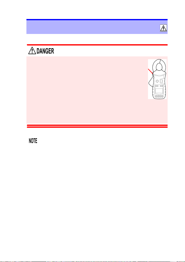
25
barrier
2.4 Measurement Procedure
2.4 Measurement Procedure
• To avoid electric shock, do not touch the portion beyond the protective barrier during use.
• When the clamp sensor is opened, do not
allow the metal part of the clamp to touch
any exposed metal, or to short between two
lines, and do not use over bare conductors.
• The maximum allowable current is 100 A AC
continuous or 200 A AC for 2 minutes (50/60 Hz). Currents
in excess of these values must be avoided as they may
damage the instrument or cause bodily injury.
• The tips of the clamp sensor are prec isely manufactured in order to provide a high level of precision. Exercise caution when handling the clamp so as to avoid
subjecting it to excessive vibration, mechanical shock,
or force.
• If foreign matter gets stuck between the tips of the
clamp sensor, do not forcibly open or close the sensor,
but rather use a soft brush or similar implement to
carefully remove the foreign matter. Accurate measurements cannot be made while foreign matter is
stuck between the tips of the clamp sensor or while the
shape of the clamp sensor is deformed. If the tips of
the clamp sensor become deformed, have the instrument inspected and calibrated by your dealer.
Page 30
2.4 Measurement Procedure
26
RmR
x
1
1
R
i
-----
i 1=
n
∑
------------------+=
R
x
1
1
R
i
-----
i 1=
n
∑
------------------»
R
x
R
1
R
n
R
2
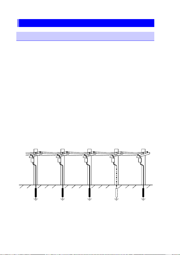
Resistance Me asur e men t
Measuring Principle
As illustrated below, the instrument is designed to measure
grounding resistance at multiple grounding locations. (*For applications involving the measurement of grounding resistance at a
single grounding site, use Hioki’s 3151 EARTH HiTESTER.)
If the grounding resistance of the measurement target is represented by R
grounded locations are represented by R
and the grounding resistance values of other
x
, R2, …, Rn, the resis-
1
tance value measured by the product is as follows:
If n is sufficiently large and each Ri value is sufficiently small,
and the second term can be ignored, allowi ng the value of
to be measured.
R
x
Page 31

2.4 Measurement Procedure
27
R
x
R
1
R
n
R
x
Example with actual measured values
The following provides an example with actual measured values.
The more grounding electrodes there are in the multiplegrounded installation, the higher the accuracy of the obtained
values. Alternately, if even one grounding electrode has a small
value (for example, 1 Ω), accurate values can be approached
even if there are few grounding electrodes. Since m ost m ultiplegrounded systems have a large number of grounding electrodes, the error can be limited.
Measuring method
Select resistance measurement mode.
1.
Select resistance measurement mode with the A/Ω key.
Clamp the grounding wire you wish to measure.
2.
The resistance value will be displayed.
Page 32

2.4 Measurement Procedure
28
• Do not measure the sam e location with two or more
Clamp On Earth Testers at the same time. The instruments will interfere with each other, preventing accurate measurement.
• Verify that the mark is not lit up.
When the current flowing through the grounding wire is high
(approximately 2.5 A or great er w ith a commercial frequency
of 50/60 Hz, approximately 100 mA or greater with a harmonic component of 1 kHz), the current will affect measured
values, making it impossible to measure the resistance.
Check the current flowing through the grounding w ire.
*The current level a t which the mark lit u p depe nds on
individual differences as we ll as the frequen cy. The closer to
the injected signal frequency, the smaller the noise current
that will affect operation.
• Open display
The screen will show [OPEn] if the clamp is not completely closed. Close the clamp completely and repeat
the measurement.
*If an extremely lar ge curren t is flowi ng throug h the groundi ng
wire or a DC current is superposed, the screen may display
[OPEn] even if the clamp is completely closed. This does not
signal a malfunction. Che ck the current flowing through the
grounding wire by using the instrument's current measurement mode or an instrument such as a clamp tester capable
of DC current measurement.
• Inductor mark
If the [ ] mark next to the resistance mark light up
during measurement, there may be a short in the
ground wire. It is recommended to verify that there are
no shorts in the location being measured.
• Capacitance mark
[]
If the
mark next to the resistance mark light up
during measurement, there may be a break in the
ground wire. It is recommended to verify that there are
no wiring breaks in the location being measured.
Short Break
[]
[]
R
x
R
R
1
x
R
x
R
R
1
x
Page 33

2.4 Measurement Procedure
29
Current Measurement
Select current measurement mode with the A/Ω key.
1.
Position the conductor in the center of the clamp
2.
sensor.
The current RMS value will be shown on the display .
3.
Page 34

2.4 Measurement Procedure
30
OK NG
• The frequency of special waveforms such as at the
secondary side of an inverter may not be indicated correctly.
• Depending on the magnitude and frequency of the
input current, resonances may be heard from the
clamp jaw. This does not affect the measurement.
• Do not input a current in excess of the maximum allowable current for the current range being used.
Page 35

31
Measuring zero-phase current
Single-phase, 2-lead circuits
three-phase 3-lead circuits
clamp all three leads of the
circuit
Load
device
Load
device
lg
When measuring zero-phase current, clamp all of the circuits at
once.
2.4 Measurement Procedure
Page 36

2.4 Measurement Procedure
32
Do not input current that exceeds the maximum continuous input of the electric current range.
• Measurement may not be accurate in the cases below.
(1) When there is large current (of about 100 A) flo w-
ing through a nearby electric line
(2) Note that a value of several tens of amperes may
be displayed when opening or closing the clamp
sensor, or when changing the electric current
range. This is not an error. It may take some time
for the display to return to zero. However, starting
measurement before the display returns to zero will
not affect measurement.
• Enable the "Filter function (Rejecting noise) (p.34)"
when conducting measurement in the cases below.
(1) When meaningless data is displayed due to noise.
(2) When using the instrument to measure special
waveforms, such as those on the secondary side of
an inverter
The instrument may not be able to pe rform measure-
ment in the cases below.
(1) When using input current that is 1/10 or less of the
full electric current range
(2) When measuring high frequencies with the filter
function enabled.
Page 37

2.5 Convenient function
33
2.5 Convenient function
Data hold function (Holding the measured value)
This function holds the measured value and continues to display
that value.
Press the HOLD key. The instrument will beep twice and the
[ ] mark will be displayed, an d the measured value will be
held. The HOLD key will flash. To cancel hold mode, press the
HOLD key again. The instrument will beep once and the [ ]
mark will disappear, and the HOLD key will stop flashing.
Backlight function
(Making measurements in a dark location)
This function makes the display easier to see in dark locations.
Press the BACKLIGHT key ( ). The backlight will turn on.
The backlight will turn off automatically when there has been no
operation for about 2 minutes.
To turn off the backlight, press the BACKLIGHT key ( ) again.
The backlight will turn off.
Page 38

2.5 Convenient function
34
Filter function (Rejecting noise)
This function allows you to reject unneeded frequency components such as high-frequency noise.
Press the FILTER key. The [ ] mark will be displayed. To
cancel the filter, press the FILTER key again. The [ ] mark
will disappear.
During resistance measurement
Using the filter function when there is a significant amount
of variation in measured values during resistance measurement will cause the measured values to stabilize.
*Note that noise rejection cannot be used when the [
mark is lit up.
During current measurement
Using the filter function enables a low-pass filter, causing
the harmonic component to be eliminated from measured
values. Widespread use of switching power supplies and
inverters has led to cases where harmonic components are
superimposed on current waveforms; the filter funct ion is
effective in such cases. Canceling the filter function disables the low-pass filter, allowing measurement of current
including harmonic components.
]
Page 39

2.5 Convenient function
35
Alarm Settings screen for resistance measurement
Alarm Settings screen for current measurement
Alarm function
(Judging measured values and s ound ing an alarm )
You can sound an alarm (A h igh tone signifies a high alarm,
while a low tone signifies a low alarm.) using previously set
thresholds by pressing the key.
Thresholds and other settings must be configured in advance.
To cancel the alarm function, press the key again.
Configuring the alarm settings
1.
Press the Fn key to switch to function mode. Using the ▼
and ▲ keys, select the resistance or current Alarm Settings
screen and press the OK key.
*For more information about function mode, see (p.50).
Page 40

2.5 Convenient function
36
Lo: The alarm will sound if the measured value
is less than the set threshold value.
Hi: The alarm will sound if the measured value
is greater than the set threshold value.
*The Hi/Lo setting is save d once the following setting has been
configured. If you press the
Fn key after configuring the Hi/Lo set-
ting but before saving the threshold and thereby cancel the configuration process, any changes to the Hi/Lo setting will not be
saved.
Set the alarm type (Hi/Lo).
2.
Using the ▼ and ▲ keys, select the alarm type (Hi/Lo), and
press the OK key. The next threshold setting will st art flas hing.
Page 41

2.5 Convenient function
37
Set the threshold.
3.
After configuring the Hi/Lo setting, set the threshold.
Using the ▼ and ▲ keys, set the threshold and press the
OK key.
You can move more quickly through threshold values by
pressing and holding the ▼ and ▲ keys.
Once the settings are complete, the screen will switch to
the Alarm Settings screen. To return to resistance measurement or current measurement mode, press the Fn key
again or the A/Ω key.
Page 42

2.5 Convenient function
38
Memory number
When the number of values saved in the instrument ’s memory
reaches 2,000, the display will show “FULL,” and you will not
be able to save additional values. Delete unneeded values to
free up space.
Memory function (Saving measurement data)
Press the MEM key in either resistance measurement mode or
current measurement mode. The instrument will beep three
times and the displayed measured value will be stored along
with the memory number (1 to 2,000) in the instrument’s internal
memory.
* Measured values, filter use, and the [ ] and [ ]
marks are saved in memory.
Page 43

2.5 Convenient function
39
Loading a value from the instrument’s internal memory
Press the Fn key to enter function mode.
1.
Using the ▼ and ▲ keys, select the Read Memory
screen and press the OK key.
*For more information about func tion mode, see (p.50).
Using the ▼ and ▲ keys, increment or decrement the
2.
memory number to recall the measured value for the
memory number you wish to load.
You can move more quickly through memory numbers
by pressing and holding the ▼ and ▲ keys.
To exit the Read Memory screen, press the Fn key or
the OK key.
* To return to resistance measurement or current mea-
surement mode, press the Fn key again or the A/Ω
key.
Page 44

2.5 Convenient function
40
To clear the last stored data po int
(1 value)
(The screenshot to the left indicates
that 34 values hav e been sa ved in
the instrument’s memory.)
To clear all data points
(The screen will show [ALL].)
Clearing stored data
You can clear the last stored data point (1 value) or all
stored data points.
Press the Fn key to enter function mode.
1.
Using the ▼ and ▲ keys, select the Clear Memory
screen and press the OK key. The screen will show
[CLr].
*For more information about funct ion mode, see (p.50).
Using the ▼ and ▲ keys, select either the last stored
2.
data point or all data points and press the OK key.
Page 45

2.5 Convenient function
41
The [OK?] mark will flash on the LCD once you select
the data to clear so that you can confirm your intentions.
Press the OK key again to clear the data.
• To cancel, press the Fn key.
• To return to resistance measurement or current measurement mode, press the Fn key again or the A/Ω
key.
Page 46

2.5 Convenient function
42
Making measurements with an Android™ handset
(FT6381 only)
By enabling the FT6381’s Bluetooth® function, you can transfer
measurement data to an Android™ handset to create measurement reports. For more information, refer to the help function of
the FT6381 Communication Software, an app for Android™
handsets.
In addition to installing the application, the following two sets of
connection settings must be configured in order to use the Blue-
®
function:
tooth
• Pairing the Android™ handset and FT6381
• Registering the FT6381 connection with the FT6381 Communication Software
Use the following procedure to configure the connection settings:
Measurement process
Enable the FT6381’s Bluetooth® function.
1.
Pair the instrument with the Android™ hand-
2.
set.
Install the FT6381 Communication Software
3.
on the Android™ handset.
Register the instrument you wish to connect
4.
with the FT6381 Communication Software.
(p.43)
(p.44)
(p.45)
(p.46)
Page 47

2.5 Convenient function
43
Enabling the Bluetooth® function on the FT6381
Press the Fn key to enter function mode.
1.
*
For more information about function mode, see (p.50).
Using the ▼ and ▲ keys, select the Bluetooth® Setting
2.
screen and press the OK key.
Using the ▼ and ▲ keys, select “on” on the Bluetooth
Setting screen and press the OK key to enable the Blue-
®
function.
tooth
Use of Bluetooth® functionality shortens the battery life
compared to normal use. It is recommended to turn off
Bluetooth
®
functionality when not in use.
®
Page 48

2.5 Convenient function
44
0000
Pairing is only necessary the first time you use the instrument with the handset. When using multiple FT6381 instruments, you will need to pair each instrument.
2
4
Enter
3
Pairing the instrument with an Android™ handset
(first use only)
Select [Wireless and Networks] from the Android™
1.
handset’s Settings button.
After enabling the Bluetooth® function, select [Scan for
2.
devices] from [Bluetooth settings] (exact words varies
with the specific Android™ handset being used; variants
include “Search for devices” and “Detect nearby terminals”).
When the handset d iscov ers [ FT6381#XX XXXXXXX] (where
3.
“XXXXXXXXX” is the serial number found on the back of the
instrument), pair the instrument.
Note that previousl y paired devices may appear in a separate
column labeled with language such as “Paired devices” rather
than in the search results.
Enter [0000] as the PIN number.
4.
Page 49

2.5 Convenient function
45
Enter and search.
Download
*The screen contents vary with the specific Android™ handset
being used. For more information about Bluetooth
®
device pairing methods and related procedures, see your Android™ handset’s instruction manual.
Installing the FT6381 Communication Software on
the Android™ handset
Search for “FT638” on the Google Play™ store and download
and install the FT6381 Communication Software.
A Google account is required in order to download applications
from the Google Play™ store. For more information about how
to register for a Google account, contact the st ore from which
you purchased the Android™ handset.
Page 50

2.5 Convenient function
46
Select
The application is free, but the user is responsible for
any Internet connection costs incurred in the course of
downloading or using the application. Since such costs
may be incurred during use of the application, it is recommended to use a fixed-price plan. Hioki is not liable
for any Internet connection costs.
Registering the instrument you wish to connect
with the FT6381 Communication Software
Turn on the FT6381.
1.
Launch the FT6381 Communication Software on the
Android™ handset. If you wish to use the map function,
enable the GPS function.
From the list of Bluetooth® devices, select [FT6381#XX
2.
XXXXXXX] and press the [Settings] button. The
FT6381 will be registered.
Once the instrument has been paired, it will connect automatically, and FT6381 measured values will be sent to the Android™
handset in real time. The instrument will not be able to connect
to the handset if it has not been paired. Refer to "Pairing the
instrument with an Android™ handset (first use only) (p .44)" to
pair the instrument.
Page 51

2.5 Convenient function
47
• The screen contents vary with the specific Android™
handset being used. F or more information ab out Blue-
®
device pairing methods and related procedures,
tooth
see your Android™ handset’s instruction manual.
• Communications between the FT6381 and Android™
handset are limited to a range of about 10 m, but
obstacles (walls, metal shielding, etc.) can shorten this
distance or prevent communications from being established.
• The FT6381’s wireless function use s Bluetooth
®
wireless technology that utilizes the 2.4 GHz band. It may
not be possible to establish communications if there is
a wireless LAN (IEEE 802.11.b/g/n) or other network/
device using the same frequency band nearby.
• The application supports Android OS 2.1 or later, but
proper operation is not guaranteed on all Android™
handsets. For more information about the devices on
which proper operation has been confirmed, see the
Google Play™ Store FT6381 Communication Software
instructions.
• Adobe’s Adobe Reader, which is available free of
charge on the Google Play™ store, is required in order
to view PDF reports. Install the application before
attempting to view reports.
• The confidentiality of information contained in Blue-
®
communications sent from the FT6381 is not
tooth
guaranteed. Hioki is not liable for any unauthorized
disclosure or other issue with measured values caused
by Bluetooth
The FT6381 emits radio radiation. Because use of
•
®
communications.
devices that emit rad io radiation requi res approval in the
country of use, be careful th at use of the instrument in a
country or region other than thos e listed on the attached
cautionary leaflet, "Precautions Concerning Use of Equipment That Emits Radio Waves" or the HIOKI products
website may be subject to penalty as a violation of law.
Page 52

2.5 Convenient function
48
Using the FT6381 Communication Software
(second and subsequent use)
After turning on the FT6381, launch the FT6381 Communication
Software on the Android™ handset. If you wish to use t he map
function, enable the GPS function. Once the instrument has
been paired, it will connect automatically, and FT6381 measured
values will be sent to the Android™ handset in real time. The
instrument will not be able to connect to the handset if it has not
been paired. Refer to "Pairing the instrument with an Android™
handset (first use only) (p.44)" to pair the instrument.
Switching the FT6381 to connect with the
Android™ handset
If you have multiple FT6381 instruments and wish to change the
unit to connect to the handset, press the Settings button after
pressing the menu button on the Android™ handset and reconfigure the Bluetooth
If you are unable to establish a Bluetooth® connection
Check the following if you are unable to establish a Bluetooth
connection between the FT6381 and the Android™ handset:
®
device settings.
®
• Is the Bluetooth
handset and the FT6381?
• Has the FT6381 in question been paired on the Android™
handset’s Bluetooth
not been paired, refer to "Pairing the instrument with an
Android™ handset (first use only) (p.44)" to pair it.
®
function enabled on both the Android™
®
settings screen? If the instrument has
Page 53

2.5 Convenient function
49
About the FT6381 Communication Software
The application provides the following functionality:
Sending measurement data (from the LCD display) to the
Android™ handset in real time
Saving and viewing measurement data (including time
stamp, GPS position data for the measurement location,
and map data)
Creating reports from measurement data
• Single reports created from measurement data from one
location
• Summary reports that present a summ ary of multiple sets
of measurement data (with the ability to add comments
and change header and footer information)
Outputting measurement data as a CSV file
Sending measurement data as an e-mail
Downloading the contents of the FT6381’s internal memory
For more information about the FT6381 Communication Software application, refer to the application help.
Page 54

2.5 Convenient function
50
Current alarm settings (p.29)
Loading values from memory (p.39)
Clearing data from the
instrument’s memory (p.40)
Resistance Alarm Settings (p.27)
2.
3.
1.
While in function mode, the [ ]
mark will light up.
1.
Press the Fn key to enter function mode.
2.
Using the ▼ and ▲ keys, select the desired setting.
3.
Accept the setting with the OK
key.
Press the Fn key or the A/Ω key
to exit function mode.
*FT6381 only
Bluetooth® Setting (p.42)
Function mode
In function mode, the follow ing s et tings and operations are available:
• Resistance alarm settings • Current alarm settings
• Loading values from memory • Clearing data from the instrument’s
• Bluetooth
®
setting
memory
Page 55

51
2.6 Advanced Settings and Functions
Press the POWER key
while holding down the
Fn key.
1
2
Advanced settings can be configured in sub-function mode. In
sub-function mode, the following settings and operations are
available:
• Measurement range displa y setting (p.52 )
• Auto-power-saving (APS) setting (p.53)
• System reset (to revert to factory settings) (p.54)
To enter sub-function mode, turn on the instrument by pressing
the POWER key while holding down the Fn ke y.
2.6 Advanced Settings and Functions
To exit sub-function mode, press the POWER key to turn off t he
instrument and then turn it back on.
Page 56

2.6 Advanced Settings and Functions
52
Enabling/disabling the measurement ra nge display
function
Enter sub-function mode.
1.
Press the POWER key while holding down the Fn key.
Using the ▼ and ▲ keys, select the Range Display Setting
2.
screen and press the OK key.
Using the ▼ and ▲ keys, switch the range display function
3.
on or off and press the OK key.
The measurement range is displayed using values only.
(Example: 1,600 Ω range 1,600)
The units for the measurement range are the sam e as
for the displayed measured value.
Page 57

2.6 Advanced Settings and Functions
53
The APS function is enabled
when the screen shows [on].
Enabling/disabling the auto-power-saving (APS)
function
The auto-power-saving (APS) function prevents unintentional
battery consumption when you forget to turn off the instrument.
The APS function activates automatically when the instrument is
turned on. The instrument will automatically turn off once about
5 minutes pass without any operation (an alarm will sound for
about 10 seconds first).
Pressing any key while the alarm sounds will reset the time
before the instrument turns off to about 5 minutes.
Enter sub-function mode.
1.
Press the POWER key while holding down the Fn key.
Using the ▼ and ▲ keys, select the APS Setting screen
2.
and press the OK key.
Using the ▼ and ▲ keys, switch the APS function on or off
3.
and press the OK key.
When the APS function is disabled in sub-function mode,
APS will remain disabled when the instrument’s power is
cycled.
Page 58

2.6 Advanced Settings and Functions
54
To disable APS temporarily
Turn on the instrument by pressing the POWER key
while holding down the HOLD key to disable APS until
the next time the instr umen t’ s power i s cycl ed. Th e next
time the power is cy cled, APS will be en abled (as lo ng
as the APS setting is enabled in sub-function mode).
Reverting the instrument to factory settings
(system reset)
This section describes how to initialize the instrument’s settings.
All measurement data (up to 2,000 values) will be deleted.
Enter sub-function mode.
1.
Press the
Using the ▼ and ▲ keys, select the System Rese t screen
2.
and press the
Press the OK key again. The instrument wil l rever t to the fac-
3.
tory settings.
POWER
key while holding down the Fn key.
OK
key . Th e
[OK?]
mark will flash.
• If the System Reset screen is displayed by mistake,
cycle the instrument's power without pressing the OK
key. Instrument operation will be restored without a
system reset having been performed.
For more information about how to clear previously saved
•
measurement data, see "Clearing stored data (p.40)".
Page 59

3.1 Measurement Specifications
55
Specifications Chapter 3
3.1 Measurement Specifications
Common measurement specifications
Guaranteed
accuracy period
Accuracy guarantee for temperature and humidity
Temperature
characteristics
Maximum rated
voltage to earth
Resistance measurement specific atio ns
Guaranteed
accuracy
conditions
Measurement
Method
Injected signal
frequency
Injected voltage
level
Effective
measuring range
Zero suppression Less than 0.02 Ω
Overrange Greater than 1600 Ω
Measurement
response time
1 year (Opening and Closing of the Sensor: Maximum 10000
times)
23°C±5°C (73°F±9°F) 80%RH or less (non-condensation)
-10 to 50°C Measurement accuracy x 0.1/°C (except 23°C±5°C)
600 VAC measurement category IV (anticipated transient over voltage 8000 V)
No reactance component, no noise current
Analog synchronous detection method (effective resistance measurement)
Approx. 2.4 kHz
Approx. 9.0 mV (with load open)
0.02 Ω to 1600 Ω
Filter: OFF/ON Approx. 3 sec /Approx. 9 sec.
Page 60

3.1 Measurement Specifications
56
Range
(Accuracy Range)
0.20 Ω (0.02 Ω to 0.20 Ω) 0.01 Ω ±1.5%rdg.±0.02 Ω
2.00 Ω (0.18 Ω to 2.00 Ω) 0.01 Ω ±1.5%rdg. ±0.02 Ω
20.00 Ω (1.80 Ω to 20.00 Ω) 0.01 Ω ±1.5%rdg.±0.05 Ω
50.0 Ω (18.0 Ω to 50.0 Ω*)0.1 Ω ±1.5%rdg.±0.1 Ω
100.0 Ω (50.0 Ω
200.0 Ω (100.0 Ω
400 Ω (180 Ω to 400 Ω*)1 Ω ±5%rdg.±5 Ω
600 Ω (400
1200 Ω (600 Ω* to 1200 Ω*) 10 Ω ±20%rdg.
1600 Ω (1200Ω* to1600 Ω) 20 Ω ± 35%rdg.
*To obtain the measurement accuracy at a range boundary, apply the accuracy of the
higher-accuracy range.
*
to 100.0 Ω*)0.1 Ω ±1.5%rdg.±0.5 Ω
*
to 200.0 Ω)0.2 Ω ±3.0%rdg.±1.0 Ω
Ω*
to 600 Ω*)2 Ω ±10%rdg.±10 Ω
Resolution Accuracy
Page 61

3.1 Measurement Specifications
57
Frequency [Hz]
Gain [db]
Current measurement specifications
Guaranteed accuracy conditions
Measurement
method
Crest factor 5.0 or less (for the 60 A range, 1.7 or less)
Conductor
position effects
Magnetic field
interference
Maximum allow-
able input
Sine wave input
Digital sampling method (true RMS measurement)
Within ±0.5% rdg. (using the center of the senso r as the reference ,
in all positions)
10 mA or less in an external magnetic fie ld of 400 A/m at 50/6 0 H z
AC
100 A AC continuous, 200 A AC for 2 minutes (50/60 Hz)
For frequency derating characteristi cs during continuou s input, see
the following diagram:
Effective
measuring range
Zero-suppression
Overrange Greater than 60.0 A
Measurement
response time
0.05 mA to 60.0 A
Less than 0.05 mA
Approx. 1 sec.
regardless of whether the filter is set to OFF or ON.
Page 62

3.1 Measurement Specifications
58
Range
(Accuracy Range)
20.00 mA
(1.00 mA to
20.00 mA)
200.0 mA
(18.0 mA to
200.0 mA)
2.000 A
(0.180 A to
2.000 A)
20.00 A
(1.80 A to
20.00 A)
60.0 A
(18.0 A to
60.0 A)
Resolu-
tion
0.01mA
0.1mA
0.001 A
0.01 A
0.1 A
Guaranteed
accuracy
frequency range
45 ≤ f ≤ 66 Hz
30 ≤ f < 45 Hz
66 < f ≤ 400 Hz
45 ≤ f ≤ 66 Hz
30 ≤ f < 45 Hz
66 < f ≤ 400 Hz
45 ≤ f ≤ 66 Hz
30 ≤ f < 45 Hz
66 < f ≤ 400 Hz
45 ≤ f ≤ 66 Hz
30 ≤ f < 45 Hz
66 < f ≤ 400 Hz
45 ≤ f ≤ 66 Hz
30 ≤ f < 45 Hz
66 < f ≤ 400 Hz
Accuracy
Filter off Filter on
±2.0%rdg.
±0.05 mA
±2.5%rdg.
±0.05 mA
±2.0%rdg.
±0.5 mA
±2.5%rdg.
±0.5 mA
±2.0%rdg.
±0.005 A
±2.5%rdg.
±0.005 A
±2.0%rdg.
±0.05 A
±2.5%rdg.
±0.05 A
±2.0%rdg.
±0.5 A
±2.5%rdg.
±0.5 A
±2.0%rdg.
±0.05 mA
±2.0%rdg.
±0.5 mA
±2.0%rdg.
±0.005 A
±2.0%rdg.
±0.05 A
±2.0%rdg.
±0.5 A
--
--
--
--
--
Page 63

3.2 General Specifications
59
3.2 General Specifications
Location for use P ollution Degree 2, altitude up to 2000 m (6562-ft.)
Storage
temperature
and humidity
Operating
temperature
and humidity
Dielectric strength
Applicable
standards
Dust and water
protection
Power supply LR06 alkaline battery × 2 (3 VDC)
Maximum rated
power
Continuous
operating time
Dimensions Approx. 73 W×218 H ×43 D mm (2.87” W×8.58”H × 1.69”D) ( exclud-
Maximum
measurable conductor diameter
Mass Approx. 620g (21.9 oz) Except for the battery
Accessories Carrying case (1), Resistance check loop (1), Strap (1),
Display specifications
LCD display Max. 2,000 count
Display refresh
rate
Range switching Auto-range
Overrange
display
Data hold
display
-20 to 60°C (-4.0°F to 140°F), 80%RH or less (non-condensation,
except for the battery)
Temperature : -10 to 50°C (14°F to 122°F)
Humidity : 80%RH or less (non-condensation)
Between the Case and the Clamp core 7400 Vrms 1 minute
Safety : EN61010
EMC : EN61326
Effects of radiated, radiofrequ ency, electro magnetic field: At 3 V/m,
5X accuracy specifications or less (resistance measurement)
IP40 (EN60529)
*With clamp sensor closed.
450 mVA
Approx. 35 hours (25 Ω measurement, backlight off,
Bluetooth® OFF (Model FT6381), 23°C reference
ing projections)
φ32 mm
LR06 alkaline battery × 2, Instruction manual (1)
Approx. 2 times/sec.
[O.L] display
mark lights up.
Page 64

3.2 General Specifications
60
Function mode
display
Filter display mark lights up.
Auto-power-save
display
Remaining
battery display
Memory number
display
Range display mark lights up.
Alarm display mark lights up.
Confirmation of
memory erasure
and reset
operation
Noise mark
display
mA/A unit
display
Ω unit display Ω mark lights up.
AC current mark
display
Resistance mark
display
Inductance mark
display
Capacitance
mark display
Bluetooth®
display
mark lights up. Flashes in subfunction mode.
mark lights up
Display of remaining battery power in 4 stages ( )
mark lights up.
mark lights up.
mark lights up.
(When there is a superimposed noise current during resistance
measurement, accuracy cannot be guaranteed.)
mA mark or A mark lights up.
mark lights up (during AC current measurement).
mark lights up (during resistance measurement).
mark lights up (when the phase angle θ > approx. 45° dur-
ing resistance measurement).
mark lights up (when the phase angle θ < approx. -4 5° during resistance measurement).
Bluetooth® function off: mark turns off (Model FT6381).
Bluetooth® function on/communications inactive: mark lights up
(Model FT6381).
Bluetooth® function on/communications active: mark flashes
(Model FT6381).
Page 65

3.2 General Specifications
61
Function specifications (underline: default v a lu e )
Data hold function
Backlight functionAutomatically turns off approx. 2 min. after last key operation.
Filter function
Resistance
measurement
filter function
Current
measurement
filter function
Alarm function
Resistance alarm
function
Current alarm
function
Alarm Hi/Lo Separate Hi/Lo settings for resistance measurement and current
Alarm threshold
setting range
Memory function
Memory capacity 2,000 values
Auto-power-save
function
Function mode
Moving between
items
Resistance alarm
function
Current alarm
function
Loading memory
values
Clearing
memory values
Bluetooth®
operating setting
Moving average time: Max. 9 sec.
Cutoff frequency: 180 Hz ±30 Hz (-3 dB)
Resistance measurement mode alarm: Beeps when measured
value is less than or greater than threshold.
Current measurement mode alarm: Beeps when measured value
is less than or greater than threshold.
measurement
Resistance measurement: Hi.AL/Lo.AL
Current measurement: Hi.AL/Lo.AL
Resistance measurement: 0.02 Ω to 1,600 Ω
Resistance measurement initial value: 25.0 Ω
Current measurement: 0.05 mA to 200.0 mA, 0.201 A to 60.0 A
Current measurement initial value: 1.00 mA
Instrument automatically turns off approx. 5 min. after last key
operation.
After selecting setting item with ▼ and ▲ keys, accept with OK
key.
AL Ω: Resistance Hi/Lo, threshold settings
AL A: Current Hi/Lo, threshold settings
MEM READ: Load memory values.
MEM CLR: Clear last saved memory value or all values.
BT: ON/OFF (FT6381)
Page 66

3.2 General Specifications
62
Sub-function mode
Range display
function
Auto-power-save
function
System reset SYS RST
Bluetooth®
function
(FT6381)
RNG: ON/OFF
APS: ON/OFF
Bluetooth® 2.1+ EDR (Class 2)
Communication range: 10 m (Line-of-sight)
Displays measured values on the screen of an Android™ handset
via Bluetooth®.
Page 67

4.1 Cleaning
63
Maintenance and Service Chapter 4
4.1 Cleaning
If foreign matter gets stuck between the tips of the clamp sensor, do not forcibly open or close the sensor, but rather use a
soft brush or similar implement to carefully remov e the foreign
matter. Accurate measurements cannot be made while foreign
matter is stuck between the tips of the clamp sensor or while the
shape of the clamp sensor is deformed. If the tips of the clamp
sensor become deformed, have the instrument inspected and
calibrated by your dealer.
• Wipe the LCD gently with a soft, dry cloth.
• To clean the instrument, wipe it gently with a soft cloth
moistened with water or mild detergent. Never use solvents such as benzene, alcohol, acetone, ether,
ketones, thinners or gasoline, as they can deform and
discolor the case.
Page 68

4.2 Troubleshooting
64
4.2 Trou bleshooting
Inspection and Repair
If damage is suspected, check the "Before returning for
repair" section before contacting your dealer or Hioki
representative.
Transporting
• When sending the instrument for repair, remove the batteries
and pack carefully to prevent damage in transit. Include cushioning material so the instrument cannot move within the package. Be sure to include details of the problem. Hioki cannot be
responsible for damage that occurs during shipment.
• Use the original packing materials when transporting the
instrument, if possible.
Before returning for repair
Symptom Cause Remedy
No screen is displayed even
when the instrument is turned on.
The screen turns
off after a little
while.
• Are the batteries
correctly inserted?
• Is the useful battery life at an end?
• Is the useful battery life at an end?
• Has the APS function been triggered?
Insert the new batteries.(p.21)
(p.53)
Page 69

4.3 Error Display
65
4.3 Error Display
If an error is shown on the LCD, the instrument needs to be
repaired. Contact your dealer or Hioki representative.
Error Display Meaning Remedial Action
E001 Main CPU program error
E002 Sub CPU program error
E003 EEPROM R/W error
E004 Adjustment data error
Please contact your dealer
or Hioki representative.
Page 70

4.3 Error Display
66
Page 71

Page 72

Page 73

FT6380
FT6381
CLAMP ON EARTH TESTER
Manual de Instrucciones
March 2014 Revised edition 1 FT6380A983-01 (A981-03)
Spanish
Page 74

Page 75

Índice
Introducción .........................................................................1
Chequeo del contenido del paquete .................................... 2
Información de seguridad .................................................... 3
Precauciones de operación ................................................. 7
Capítulo 1 Información general 11
1.1 Información general del producto ...................... 11
1.2 Características .................................................. 12
1.3 Nombres y funciones de las partes ................... 14
Botón de operación ............................................ 16
Indicadores en pantalla ...................................... 17
Capítulo 2 Medición 19
2.1 Proceso de medición ......................................... 19
2.2 Preparación para la medición ........................... 20
Montaje de correa ..............................................20
Colocación (o cambio) de las baterías............... 21
2.3 Inspección preoperativa .................................... 23
Uso del lazo de referencia de resistencia incluido
para inspeccionar el instrumento ....................... 24
2.4 Procedimiento de medición ............................... 25
Medición de la resistencia.................................. 26
Medición de corriente.........................................30
2.5 Funciones útiles ................................................34
Función de retención de datos (retención del valor
medido) .............................................................. 34
Función de retroiluminación (realización de
mediciones en lugares oscuros) ........................ 34
Función de filtro (rechazo de ruido) ................... 35
Función de alarma (evaluación de los valores
medidos y emisión de una alarma) .................... 36
Función de memoria (guardado de los datos de
medición)............................................................39
i
Page 76

ii
Toma de mediciones con un celular Android™ (solo
el modelo FT6381) .............................................43
Activación de la función de Bluetooth® en el modelo
FT6381 ...............................................................44
Emparejamiento del instrumento con un celular
Android™ (solo la primera vez) ..........................45
Instalación de la aplicación FT6381 Communication
Software en un celular Android™....................... 46
Registro del instrumento que desea conectar
mediante la aplicación FT6381 Communication
Software .............................................................47
Cambio de instrumento FT6381 a conectar con el
celular Android™................................................49
Utilización de la aplicación FT6381 Communication
Software (la segunda vez y posteriores) ............49
2.6 Ajustes y funciones avanzados .........................52
Activación/desactivación de la función de
visualización del rango de medición...................53
Activación/desactivación de la función de ahorro
automático de energía (APS) .............................54
Restablecimiento del instrumento a la configuración
de fábrica (restablecimiento del sistema) ...........55
Capítulo 3 Especificaciones 57
3.1 Especificaciones de medición ...........................57
3.2 Especificaciones generales ...............................61
Capítulo 4 Mantenimiento y servicio 65
4.1 Limpieza ............................................................65
4.2 Resolución de problemas ..................................66
Inspección y reparación......................................66
Antes de devolver para su reparación ................66
4.3 Visualización de errores ....................................67
Page 77

Introducción
Introducción
Gracias por adquirir el MEDIDOR DE RESISTENCIA DE TIERRA TIPO GANCHO modelo FT6380, FT6381 de HIOKI. Para
obtener el máximo rendimiento del instrumento, lea primero este
manual y téngalo a mano para futuras consultas.
Marcas comerciales registradas
®
• Bluetooth
SIG, Inc. (EE.UU.).
• Android
de Bluetooth
• Adobe y Reader son marcas comerciales registradas o marcas comerciales de Adobe Systems Incorporated en los Estados Unidos y/o en otros países.
es una marca comercial registrada de Bluetooth
TM
Google PlayTM es una marca comercial registrada
®
Google, Inc.
1
Page 78

Chequeo del contenido del paquete
2
Chequeo del contenido del paquete
Cuando reciba el instrumento, inspecciónelo cuidadosamente
para asegurarse de que no ha sufrido ningún daño durante el
envío. En particular, chequee los accesorios, los interruptores
del panel y los conectores. Si el daño es evidente o si no funciona según las especificaciones, póngase en contacto con
su distribuidor o representante de Hioki.
Contenido del paquete
Confirme que se incluyen estos contenidos.
□ Medidor de Resistencia de Tierra tipo Gancho modelo FT6380 o
FT6381 (1)
□ Lazo de Referencia para Re-
sistencia (1)
□ Manual de instrucciones (1)
□ Funda de Transporte (1)
□ Baterías alcalinas LR6 (2)
□ Correa (1)
Utilice los materiales de empaque originales cuando transporte el instrumento, si es posible.
Para el resto de notas de transporte, consulte “Transporte (p.66)”.
Page 79

Información de seguridad
Información de seguridad
Este instrumento está diseñado para cumplir con las normas de
seguridad IEC 61010 y ha superado los test de seguridad antes
del envío. Sin embargo, un manejo inadecuado durante el uso
podría provocar lesiones o la muerte, así como daños al instrumento. Sin embargo, si se utiliza el instrumento de una manera no
descrita en este manual, puede anular los elementos de seguridad que se proporcionan. Asegúrese de comprender las instrucciones y precauciones del manual antes de su uso. Negamos
cualquier responsabilidad por accidentes o lesiones que no sean
consecuencia directa de los defectos del instrumento.
Este manual contiene información y advertencias esenciales
para garantizar la seguridad durante el funcionamiento del instrumento y para su mantenimiento en condiciones de funcionamiento seguras. Antes de utilizarlo, asegúrese de leer
atentamente las siguientes precauciones de seguridad.
Símbolos de seguridad
En el manual, el símbolo indica una información
especialmente importante que el usuario debe leer
antes de utilizar el instrumento.
El símbolo impreso en el instrumento indica que el
usuario debe consultar el tema correspondiente en el
manual (marcado con el símbolo ) antes de utilizar la
función en cuestión.
Indica un dispositivo con doble aislamiento.
Indica CA (corriente alterna).
Indica que el instrumento puede estar conectado o desconectado de un circuito con corriente.
Indica el botón de encendido/apagado.
3
Page 80

Información de seguridad
4
Los siguientes símbolos en este manual indican la importancia
relativa de las precauciones y advertencias.
Indica que un funcionamiento incorrecto supone
un gran riesgo que podría provocar lesiones graves o la muerte del usuario.
Indica que un funcionamiento incorrecto supone
un riesgo importante que podría provocar lesiones
graves o la muerte del usuario.
Indica que un funcionamiento incorrecto supone la
posibilidad de provocar lesiones al usuario o
daños al instrumento.
Indica los elementos de recomendación relacionados con el rendimiento o el correcto funcionamiento del instrumento.
Símbolos de varias normas
Marca de residuos de aparatos eléctricos y electrónicos (RAEE):
Este símbolo indica que el aparato eléctrico y electrónico se lanza al mercado de la UE después del
13 de agosto de 2005 y los productores de los
Estados miembros están obligados a mostrarlo en
el aparato en virtud del artículo 11.2 de la Directiva
2002/96/CE (RAEE).
Este símbolo indica que el producto cumple con las
normas de seguridad establecidas por la Directiva
CE.
FCC ID
Indica que el producto incorpora tecnología inalámbrica Bluetooth
cial registrada de Bluetooth SIG, Inc. y se utiliza
bajo licencia por HIOKI E.E. CORPORATION.
Indica que el producto cumple con las normas técnicas nacionales de Japón establecidas en la Ley
sobre la radio (tipo de certificación).
Indica el número de identificación del módulo inalámbrico certificado por la Comisión Federal de
Comunicaciones (FCC) de los EE.UU.
®
. Bluetooth® es una marca comer-
Page 81

IC
Indica el número del módulo inalámbrico certificado
por el Ministerio de Industria de Canadá.
Otros símbolos
Indica una acción prohibida.
Información de seguridad
5
(p. n.º)
[ ]
Fn
(caracteres
en negrita)
Indica la ubicación de la información de referencia.
La información que se muestra en pantalla aparece entre corchetes.
El texto en negrita indica los caracteres alfanuméricos mostrados en los botones de operación.
La pantalla de este instrumento muestra los caracteres de la
siguiente forma.
Visualizaciones en pantalla que difieren de la notación anterior:
Visualización si se superan los parámetros
Medición de la resistencia: cuando la lectura excede los 1600 Ω.
Medición de la corriente: cuando la lectura
excede los 60,0 A.
Visualización si hay abertura
Esta pantalla se muestra cuando el sensor
de gancho no está completamente cerrado
durante la utilización de la función de medición de la resistencia.
Page 82

Información de seguridad
6
Categorías de medición
Este instrumento cumple con los requisitos de seguridad de la
CAT IV.
Para garantizar la seguridad durante el funcionamiento de los instrumentos de medición, la IEC 61010 establece cuáles son las normas
de seguridad para los diversos entornos eléctricos, categorizadas
como CAT II a CAT IV y denominadas categorías de medición.
Circuitos eléctricos principales de los equipos conectados a un tomacorriente de CA mediante un cable de
CAT II
CAT III
CAT IV
El uso de un instrumento de medición en un entorno designado
con una categoría de número superior al de aquella para la que
el instrumento está clasificado podría provocar un accidente
grave y debe evitarse cuidadosamente.
El uso de un instrumento de medición que no está clasificado como
CAT en la medición de aplicaciones de CAT II a CAT IV podría provocar un accidente grave y debe evitarse cuidadosamente.
alimentación (herramientas portátiles, electrodomésticos, etc.).
La CAT II contempla la medición directa de los tomacorrientes.
Circuitos eléctricos principales de maquinaria pesada
(instalaciones fijas) conectados directamente al panel
de distribución y los alimentadores, desde el panel de
distribución a los tomacorrientes.
El circuito desde la acometida del servicio a la entrada
de servicio y al medidor de potencia y el equipo principal de protección contra sobrecargas eléctricas (panel
de distribución).
Page 83

Precauciones de operación
Precauciones de operación
Siga estas precauciones para garantizar la seguridad durante el
funcionamiento y para obtener todos los beneficios de las diferentes funciones.
Chequeos preliminares
Antes de utilizar el instrumento por primera vez, verifique que funciona normalmente para asegurarse de que no ha sufrido ningún
daño durante el almacenamiento o el envío. Si está dañado, póngase en contacto con su distribuidor o representante de Hioki.
Instalación del instrumento
Temperatura de funcionamiento: de -10 a 50 °C
(Asegúrese de utilizar baterías adecuadas para usar en las condiciones ambientales en las que está utilizando el instrumento.) Humedad
de funcionamiento: 80 % de HR o menos (sin condensación)
Evite las siguientes ubicaciones que podrían provocar un
accidente o daños al instrumento.
Expuestas a la luz directa del sol
Expuestas a altas
temperaturas
Expuestas a agua, aceite, disolventes u otros
productos qu ímicos
Expuestas a n iveles elevados de humedad o
condensación
Expuestas a niveles
elevados de partículas de polvo
Sometidas a vibraciones
En presencia de gases
explosivos o líquidos
corrosivos
Expuestas a fuertes
campos electromagnéticos
Cerca de radiadores
electromagnéticos
Cerca de radiadores
electromagnéticos (p.
ej., sistemas de calentamiento por inducc ión de
alta frecuencia y u tensilios de cocina de calentamiento por inducción)
7
Page 84

Precauciones de operación
8
Manejo del instrumento
• Para evitar cortocircuitos y posibles peligros mortales,
nunca conecte el gancho a un circuito que opera en más
de 600 V o sobre cables conductores desnudos.
• La tensión nominal máxima entre los terminales de
entrada y la puesta a tierra es de 600 V CA. La medición
de un voltaje que sobrepase este valor con respecto a la
puesta a tierra podría dañar el instrumento y provocar
lesiones corporales.
• Para evitar una descarga eléctrica, no retire la cubierta
del instrumento. Los componentes internos del instrumento llevan voltajes altos y pueden llegar a calentarse
mucho durante el funcionamiento.
• Cuando el sensor de gancho se abre, no permita que la
parte metálica del gancho toque cualquier metal
expuesto, ni que se produzca un cortocircuito entre dos
líneas, ni lo utilice sobre cables conductores desnudos.
Para evitar una descarga eléctrica al medir las líneas con
corriente, utilice el equipo de protección adecuado, como
guantes de goma aislantes, botas y un casco de seguridad.
Page 85

Precauciones de operación
• No introduzca una corriente que sobrepase la corriente máxima permitida. Si lo hace, podría dañar el instrumento o provocar quemaduras.
La corriente máxima permitida es de 100 A CA de forma continua o de 200 A CA en un intervalo de dos minutos a 50/
60 Hz. Para obtener más información acerca de las características de reducción de potencia por frecuencia durante una
entrada continua, consulte el siguiente diagrama:
Corriente [A]
Frecuencia [Hz]
• Para evitar daños al instrumento, protéjalo de golpes durante
su transporte y manejo. Tenga especial cuidado de evitar golpes por caídas.
• Tenga cuidado de evitar la caída del instrumento o de someterlo de cualquier otra manera a un impacto mecánico que
podría dañar las superficies de contacto del núcleo y afectar
negativamente a la medición.
• Aunque este instrumento es resistente al polvo, no es completamente estanco. Para evitar posibles daños, evite su uso en
entornos polvorientos o húmedos.
• No incline el dispositivo ni lo coloque sobre una superficie irregular. Si el dispositivo se cae o se tira puede provocar lesiones o daños al dispositivo.
9
Page 86

Precauciones de operación
10
• El grado de protección de la carcasa de este dispositivo
(basada en el estándar EN60529) es *IP40. (El grado de protección se aplica al sensor de gancho cuando está en posición de cierre.)
*IP40
Esto indica el grado de protección proporcionado por la carcasa
del dispositivo frente al uso en ubicaciones peligrosas, la penetración de impurezas sólidas y la entrada de agua.
4: Protegido contra el acceso a las piezas peligrosas con un
alambre que mida 1,0 mm de diámetro. Los dispositivos del
interior de la carcasa está protegida contra la penetración de
impurezas sólidas de más de 1,0 mm de diámetro.
0: Los dispositivos del interior de la carcasa no está protegida
contra los efectos perjudiciales del agua.
Page 87

1.1 Información general del producto
11
Información general Capítulo 1
1.1 Información general del producto
Los modelos FT6380 y FT6381 del Medidor de Resistencia de
Tierra tipo Gancho realizan mediciones de resistencia de puesta
a tierra simplemente al engancharse a varios cables con puesta
a tierra múltiple. No se precisa una varilla de puesta a tierra
auxiliar y no es necesario desconectar el cable de puesta a tierra de la varilla de puesta a tierra.
Los instrumentos también cuentan con una función de medición de
corriente CA y pueden medir corrientes: desde corrientes de fuga
del orden de varios mA hasta corrientes de carga de hasta 60 A.
El FT6381 emite radiaciones radioeléctricas. El uso de dispositivos que emiten radiaciones radioeléctricas requiere la aprobación
en el país de uso, por ese motivo tenga cuidado al utilizar este
instrumento en un país o región distinto a los enumerados en el
folleto de precauciones adjunto, “Precauciones relativas al uso de
equipos que emiten ondas de radio”, o en el sitio web de los productos HIOKI, ya que este uso puede sancionarse como una
infracción de la ley.
Page 88

1.2 Características
12
1.2 Características
Sensor compacto
El sensor compacto se puede utilizar para engancharlo a los cables
con puesta a tierra con facilidad. El diseño del sensor acelera considerablemente el proceso de medición, eliminando la necesidad de
extraer los cables de puesta a tierra para su enganche o de escarbar
alrededor de la varilla o cable de puesta a tierra.
Amplio rango dinámico
El instrumento puede medir fácilmente la resistencia de puesta a tierra de 0,02 a 1600 Ω gracias a su función de rango automático. La
medición de la corriente comprende desde pequeñas corrientes de
fuga (resolución máxima de 10 μA) hasta un máximo de 60 A.
Función de chequeo de ruido (p.28)
El instrumento detecta automáticamente el ruido que puede afectar
a la medición de la resistencia de puesta a tierra y muestra la marca
.
Visualización del valor eficaz RMS (RMS Verdadero)
El cálculo del valor eficaz RMS permite que el instrumento mida con
precisión la distorsión en forma de onda de las corrientes.
Función de retención de datos (p.34)
Un botón grande que se pulsa con facilidad le permite retener el valor medido. El botón notifica al usuario del estado de la retención
parpadeando mientras se retiene el valor.
Función de retroiluminación (p.34)
El instrumento utiliza un LED blanco para proporcionar una excelente visibilidad. De este modo los valores se pueden leer claramente,
incluso en lugares oscuros.
Page 89

1.2 Características
13
Función de ahorro automático de energía (APS) (p.54)
La función de ahorro automático de energía evita que las baterías
se agoten cuando se olvida de apagar el instrumento.
Función de alarma (p.36)
Cuando se establece un umbral, puede hacer que el instrumento
realice una evaluación como PASA/NO PASA y le notifique el resultado mediante un pitido. Puede establecer umbrales diferentes para
las mediciones de resistencia y de corriente, y seleccionar los criterios de evaluación (si se genera un resultado de NO PASA cuando
la lectura es mayor o menor que el umbral).
Función de filtro (p.35)
El uso generalizado de fuentes de alimentación conmutadas y de inversores ha dado lugar a casos en los que los componentes armónicos se superponen a las formas de onda de la corriente de fuga.
La función de filtro del instrumento le permite realizar dos tipos de
medición: corriente de fuga en relación a la degradación del aislamiento y corriente de fuga incluyendo este componente armónico.
Memoria interna (p.39)
La memoria interna del instrumento puede registrar hasta 2000 valores medidos.
Función de informe automático de medición con
conectividad Android
El modelo FT6381 cuenta con tecnología inalámbrica Bluetooth® y
se puede conectar a un smartphone con sistema operativo Android
para crear fácilmente informes de medición en sitio. (La disponibilidad del modelo FT6381 se limita a ciertos países. Para obtener más
información, póngase en contacto con su distribuidor o representante de Hioki.)
™ (*solo el modelo FT6381) (p.43)
Page 90

1.3 Nombres y funciones de las partes
14
1.3 Nombres y funciones de las partes
Parte frontal
FT6380 FT6381
Sensor de gancho
Barrera
Botón de encendido
(POWER)
Botón de retención
(HOLD) (p.34)
Botón A/Ω
Botón de
retroiluminación (p.34)
Indicador en pantalla
(p.17)
Botón de operación
(p.16)
Botón de
encendido
(POWER)
Botón de
retención
(HOLD)
Botón de
retroiluminación
Botón A/Ω
• Se utiliza para encender y apagar el instrumento.
• Para cancelar temporalmente la función de ahorro automático de energía, pulse el botón de encendido
mientras mantiene pulsado el botón de retención
POWER
HOLD
• Retiene la visualización del valor medido o cancela el
modo de retención.
• Para cancelar la función de ahorro automático de energía, pulse el botón de encendido POWER mientras
mantiene pulsado el botón de retención HOLD.
• Activa y desactiva la retroiluminación.
• Cambia entre el modo de medición de la resistencia y
el modo de medición de la corriente.
.
Page 91

Parte posterior
1.3 Nombres y funciones de las partes
15
FT6380
Parte inferior
N.º de serie
Tapa de las
baterías
(p.21)
FT6381
Orificio para la correa
(p.20)
Page 92

1.3 Nombres y funciones de las partes
16
Botón de operación
Botón Descripción
Cambia al modo de función, que se utiliza para configurar los
ajustes. Si pulse este botón de nuevo volverá al modo de
medición de la resistencia o al modo de medición de la
corriente.
• Activa la función de alarma. (p.36)
• Cuando se activa la función de alarma, el instrumento notificará al usuario mediante un pitido si una lectura es mayor
que (o menor que) un umbral ajustado previamente.
• Los ajustes del umbral de la función de alarma se pueden
configurar en el modo de función. (p.38)
*En el modo de función, este botón sirve como botón
se utiliza para seleccionar los elementos y valores de ajuste.
• Si pulse este botón mientras utiliza la función de medición
de corriente, se activa el filtro de paso bajo para rechazar
los componentes armónicos innecesarios. (p.35)
• Si se pulsa mientras utiliza la función de medición de la
resistencia, se activa la función de media móvil, lo que permite una medición más estable. (p.35)
*En el modo de función, este botón sirve como botón
se utiliza para seleccionar los elementos y valores de ajuste.
Guarda los datos de medición en la memoria interna del instrumento. (p.39)
*En el modo de función, este botón sirve como botón
que se utiliza para aceptar los elementos y valores de
ajuste.
▼, que
▲, que
OK,
Page 93

1.3 Nombres y funciones de las partes
Indicadores en pantalla
Se ilumina cuando se retienen los datos. (p.34)
Se ilumina en el modo de función. (p.51)
Parpadea en el modo de subfunción. (p.52)
Se ilumina cuando se activa la función de alarma. (p.36)
Se ilumina cuando se activa la función de filtro. (p.35)
Se ilumina cuando se activa la función de Bluetooth
dea cuando se envían o reciben datos. (Solo el modelo
FT6381) (p.43)
Se ilumina cuando se activa la función de ahorro automático
de energía. (p.54)
Indica el nivel de carga restante de las baterías. (p.22)
Se ilumina en el modo de medición de la corriente CA. (p.30)
Se ilumina en el modo de medición de la resistencia. (p.26)
Se ilumina en el modo de medición de la resistencia cuando
se detecta una corriente que podría afectar el valor medido.
(p.28)
Se ilumina en el modo de medición de la resistencia cuando
el lazo de tierra medido tiene un componente de alta reactancia o un componente de capacitancia (
se ilumina el indicador [ ] debido a un valor de medición
de la resistencia bajo, es probable que el valor visualizado
indique un lazo de medición cortocircuitado en lugar de una
resistencia de puesta a tierra normal. Cuando se ilumina el
indicador [
cuito. En este caso, el indicador señala que los cables se han
acoplado por capacitancia.) (p.28)
], el lazo podría presentar una apertura de cir-
±45° o más). (Cuando
®
. Parpa-
17
Page 94

1.3 Nombres y funciones de las partes
18
Se ilumina durante las operaciones de la memoria interna.
(p.39)
El número de puntos de datos de medición almacenados en
la memoria se muestra a la derecha.
Se ilumina cuando se activa la función de visualización del
rango.
El rango de medición se muestra a la derecha.
Page 95

2.1 Proceso de medición
Medición Capítulo 2
2.1 Proceso de medición
1
Preparación para la medición
Inspección preoperativa (p.23)
Uso del lazo de referencia de resistencia incluido para ins-
peccionar el instrumento (p.24)
2
Medición
Medición de la resistencia (p.26)
Medición de corriente (p.30)
3
Fin de la medición
Retire el instrumento del objeto de medición.
Apague el instrumento.
19
Page 96

2.2 Preparación para la medición
20
2.2 Preparación para la medición
Luego de adquirir el instrumento
Complete los siguientes pasos antes de utilizar el instrumento
para realizar mediciones.
Montaje de correa
Coloque ambos extremos de la correa al instrumento con firmeza.
Si no se colocan con firmeza, el instrumento se podría caer y
dañar durante su transporte.
Pase la correa por el orificio para la correa, como se muestra en
el siguiente diagrama:
Page 97

2.2 Preparación para la medición
21
Colocación (o cambio) de las baterías
Antes de utilizar el instrumento por primera vez, coloque dos baterías alcalinas de tamaño AA (LR6). Verifique que haya suficiente
carga restante en las baterías antes de la medición. Si la carga restante de las baterías no es suficiente, cambie las baterías.
• Para evitar una descarga eléctrica al cambiar las baterías,
desconecte primero el gancho del objeto a medir.
• Luego de cambiar las baterías, vuelva a colocar la tapa y
los tornillos antes de utilizar el instrumento.
• Las baterías pueden explotar si se manejan de forma
incorrecta. No cortocircuite, recargue, desmonte ni se
deshaga de ellas echándolas al fuego.
• Manipule y deseche las baterías conforme a las regulaciones locales.
• No mezcle baterías nuevas y usadas o tipos de baterías diferentes. Además, tenga cuidado con la polaridad de las baterías durante la colocación. De lo contrario, podría provocar un
rendimiento mediocre o daños por fugas en las baterías.
Para evitar la corrosión por fugas en las baterías, retire las bate-
•
rías del instrumento si no se va a utilizar durante mucho tiempo.
•
El indicador se ilumina cuando el voltaje de las baterías
es bajo. Cambie las baterías tan pronto como sea posible.
•
Antes de cambiar las baterías, asegúrese de que el interruptor deslizante está apagado: en la posición OFF.
• Luego de usar, desconecte siempre la alimentación.
• Si las baterías están completamente agotadas, la pan-
talla mostrará [BAttLo] y el instrumento se apagará
automáticamente.
Page 98

2.2 Preparación para la medición
22
Elementos necesarios:
• Destornillador de cabeza Phillips
• Batería alcalina LR6 (2)
Procedimiento habitual
Verifique que el instrumento está apagado.
1.
Retire los tornillos de fijación de la tapa de las bate-
2.
rías con un destornillador de cabeza Phillips.
Extraiga la tapa de las baterías.
3.
Inserte dos baterías nuevas (baterías alcalinas LR6),
4.
asegurándose de que la orientación sea la correcta.
Vuelva a colocar la tapa de las baterías y apriete los
5.
tornillos de fijación.
4
3
2
Indicador del estado de las baterías
Este indicador se muestra en la esquina superior derecha.
Cuando se han colocado baterías alcalinas nuevas.
Cuando el nivel de carga restante de las baterías es de 2/3.
Cuando el nivel de carga restante de las baterías es de 1/3.
Las baterías están agotadas. Cámbielas por baterías nuevas.
Page 99

2.3 Inspección preoperativa
2.3 Inspección preoperativa
Antes de utilizar el instrumento por primera vez, verifique que
funciona normalmente para asegurarse de que no ha sufrido
ningún daño durante el almacenamiento o el envío. Si está
dañado, póngase en contacto con su distribuidor o representante de Hioki.
1. Inspección del instrumento
23
• ¿El instrumento está dañado?
• ¿El sensor de gancho está
agrietado o dañado de cualquier otra forma?
Sí
No utilice el instrumento si está dañado, ya que puede provocar una descarga eléctrica.
Mande el instrumento a reparar.
2. Inspección del instrumento luego de encenderlo
¿La pantalla se enciende al
encender el instrumento?
Sí
Uso del lazo de referencia de resistencia incluido para inspeccionar el instrumento (p.24)
No
Fin de la inspección
Se muestra un error.
Es posible que el instrumento
no funcione cor rectamente.
Mande el instrumento a reparar.
• La pantalla no está
encendida.
• La pantalla muestra un error.
Es posible que las baterías estén agotadas. Cambie las baterías y vuelva a intentarlo.
La pantalla está prendida.
Page 100

2.3 Inspección preoperativa
24
Uso del lazo de referencia de resistencia incluido
para inspeccionar el instrumento
Antes de encender el instrumento, asegúrese de leer Precauciones de operación (p.7).
Inspección del instrumento con el lazo de referencia para
resistencia
Asegúrese que no haya sustancias extrañas metidas entre las
puntas del sensor de gancho y que el sensor se puede abrir y
cerrar sin problemas. Si es así, enganche el lazo de referencia
para resistencia incluido y asegúrese que el instrumento funciona correctamente. Asegúrese que se muestre un valor dentro
del rango admisible para cada lazo.
Lazo de referencia para re-
sistencia
Prueba de resistencia Rango admisible
1 Ω De 0,95 a 1,05 Ω
25 Ω De 24,3 a 25,7 Ω
• Si el instrumento muestra un valor fuera del rango
admisible, es necesario repararlo. Póngase en contacto con su distribuidor o representante de Hioki.
• El lazo de referencia para resistencia no se puede utilizar para calibrar el instrumento. Para calibrar el instrumento, póngase en contacto con su distribuidor.
 Loading...